
Materials and Energy-Centric Life Cycle Assessment for Drones: A Review


Abstract
1. Introduction
2. Methodology
- (1)
- UAV Material Selection and Structural Performance
- Examines traditional materials (metals, polymers, composites) and emerging alternatives like bio-based composites, hybrid laminates, and recycled carbon fibers.
- Evaluates mechanical properties such as stiffness-to-weight ratio, impact resistance, fatigue performance, and corrosion resistance.
- (2)
- Environmental Impact Assessment Using LCA
- Follows ISO 14040 guidelines with a cradle-to-grave approach covering material extraction, manufacturing, operational use, and disposal.
- Quantifies energy consumption and emissions, discussing material recovery, disposal, and recyclability challenges.
- Uses Monte Carlo simulations and sensitivity analyses to model uncertainty and variability in LCA data.
- (3)
- Optimizing UAV Material Selection
- Applies Multi-Criteria Decision Making (MCDM) to rank materials based on recyclability, emissions, and energy demand.
- Explores probabilistic vs. deterministic modeling for improved UAV material assessments.
- Highlights future challenges, such as integrating aerodynamic performance into LCA models and advancing UAV material circularity.
3. Materials Used for UAV Construction
3.1. External Skin and Body
3.2. Propeller Materials
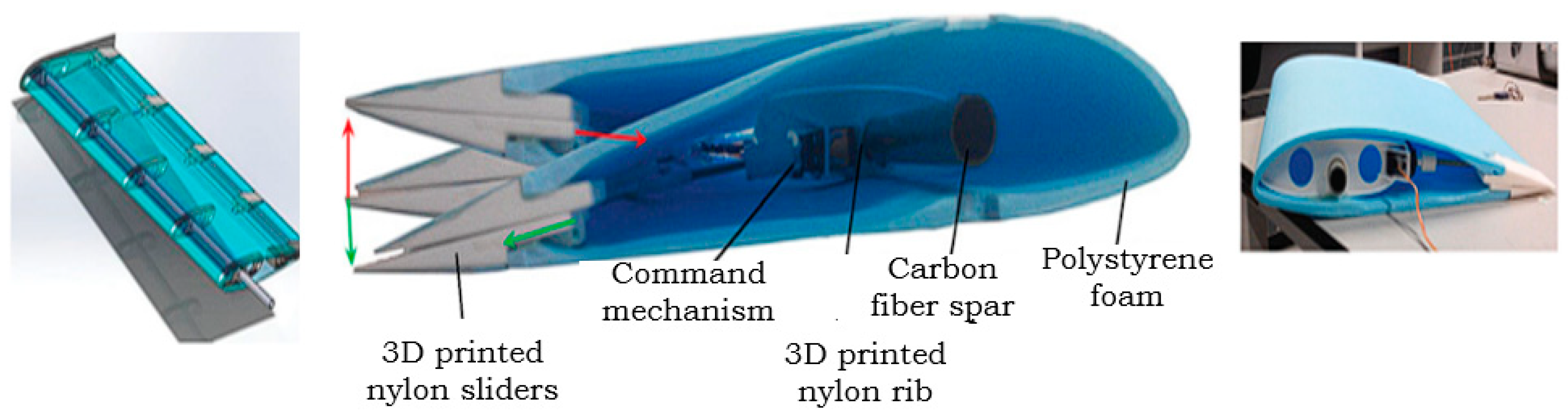
3.3. Wings and Tails
3.4. Support Frame
4. Life Cycle Assessment
5. LCA of UAV Following ISO 14040 Framework
5.1. Goal and Scope Definition
- Comparison of energy utilization in the manufacturing of UAV structural components using different materials/composites.
- Assessing the trade-offs between mechanical performance and environmental impact of various UAV materials.
- Quantification of the environmental impact of different UAV materials in terms of energy demand (MJ/kg), carbon footprint (kg CO2-eq/kg material), material recyclability (%), and end-of-life treatment.
- Provide recommendations for UAV material selection.
5.2. Life Cycle Inventory (LCI) Analysis
5.3. Life Cycle Impact Assessment
5.4. Interpretation of Results (ISO 14044, Clause 4.5)
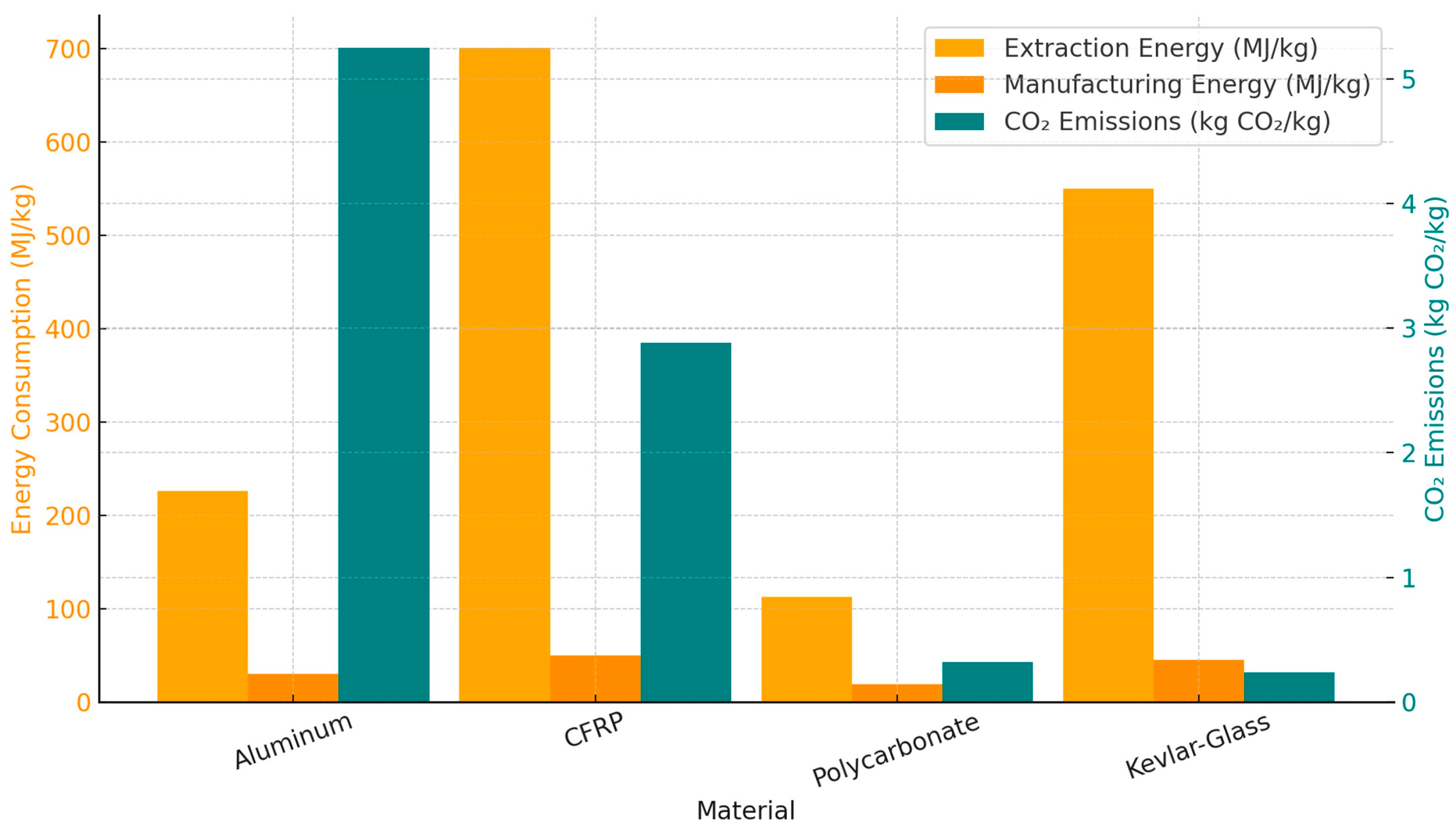
5.4.1. Comparative Energy Consumption and Carbon Footprint of Materials
5.4.2. Sensitivity Analysis and Multi-Criteria Decision Making (MCDM)
5.4.3. Advanced Sensitivity Analysis: Monte Carlo Simulations
5.4.4. Scenario Analysis: Impact of Energy Grid Mix
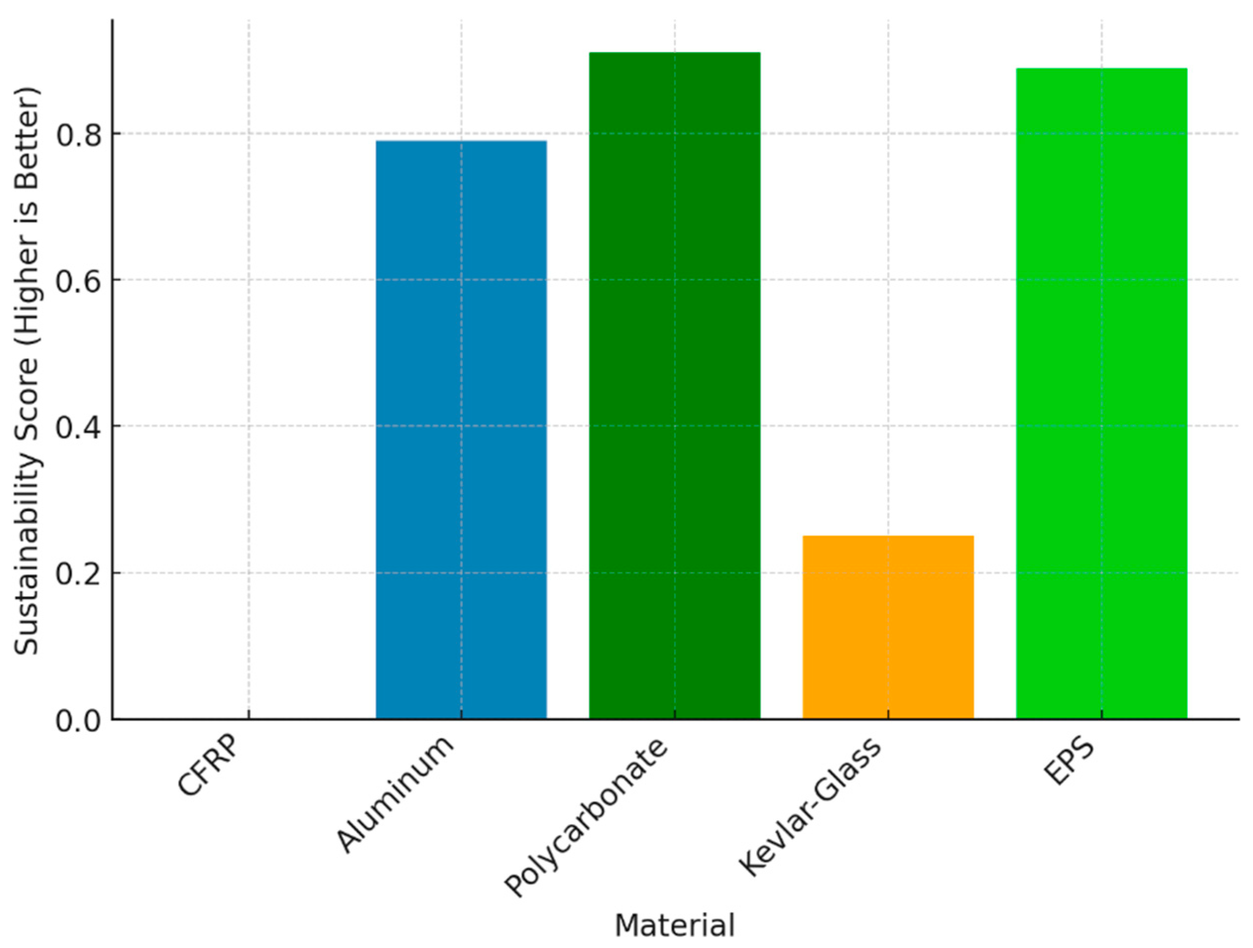
5.4.5. Optimized UAV Material Selection Results (Genetic Algorithm Analysis)
5.4.6. Limitations of the Study
6. Alternative Approach to LCA Complimenting Previous Findings
7. Emerging and Less Common UAV Materials: Potential and Limitations
8. Comparative LCA of UAVS Across Applications: A Material-Centric Perspective
- Exploring thermoplastic composites and recycled carbon fiber can mitigate the high energy demand associated with virgin CFRP manufacturing.
- Moving toward solid-state batteries, sodium-ion batteries, or structural energy-storing composites can help reduce dependence on lithium, cobalt, and nickel.
- For applications such as agriculture and low-altitude surveillance, natural fiber composites and biodegradable resins offer an eco-friendly alternative to traditional petroleum-based polymers.
9. Conclusions
Author Contributions
Funding
Informed Consent Statement
Data Availability Statement
Conflicts of Interest
References
- Salguero Paz, J.D.; Bustamante, A.A.P. Applicability of Generative Design in the Construction of UAVs. In Proceedings of the 2022 7th International Conference on Control and Robotics Engineering (ICCRE), Beijing, China, 15–17 April 2022; pp. 106–110. [Google Scholar]
- Miličević, Z.M.; Bojković, Z.S. From the Early Days of Unmanned Aerial Vehicles (UAVs) to Their Integration into Wireless Networks. Vojnoteh. Glas. 2021, 69, 941–962. [Google Scholar] [CrossRef]
- Mohsan, S.A.H.; Othman, N.Q.H.; Li, Y.; Alsharif, M.H.; Khan, M.A. Unmanned Aerial Vehicles (UAVs): Practical Aspects, Applications, Open Challenges, Security Issues, and Future Trends. Intel. Serv. Robot. 2023, 16, 109–137. [Google Scholar] [CrossRef]
- Pal, O.K.; Shovon, M.S.H.; Mridha, M.F.; Shin, J. In-Depth Review of AI-Enabled Unmanned Aerial Vehicles: Trends, Vision, and Challenges. Discov. Artif. Intell. 2024, 4, 97. [Google Scholar] [CrossRef]
- Cetinsoy, E.; Dikyar, S.; Hancer, C.; Oner, K.T.; Sirimoglu, E.; Unel, M.; Aksit, M.F. Design and Construction of a Novel Quad Tilt-Wing UAV. Mechatronics 2012, 22, 723–745. [Google Scholar] [CrossRef]
- Qian, Y.; Wei, Y.; Kong, D.; Xu, H. Experimental Investigation on Motor Noise Reduction of Unmanned Aerial Vehicles. Appl. Acoust. 2021, 176, 107873. [Google Scholar] [CrossRef]
- Saeed, A.S.; Younes, A.B.; Cai, C.; Cai, G. A Survey of Hybrid Unmanned Aerial Vehicles. Prog. Aerosp. Sci. 2018, 98, 91–105. [Google Scholar] [CrossRef]
- Trubia, S.; Curto, S.; Severino, A.; Arena, F.; Puleo, L. The Use of UAVs for Civil Engineering Infrastructures. In Proceedings of the AIP Conference Proceedings, Crete, Greece, 29 April–3 May 2020; Volume 2343. [Google Scholar]
- Karthik, M.A.; Srinivasan, K.; Srujan, S.; Subhash, H.H.S.; Suraj Jain, M. Design and CFD Analysis of a Fixed Wing for an Unmanned Aerial Vehicle. Int. J. Latest Eng. Res. Appl. (IJLERA) 2017, 2, 77–85. [Google Scholar]
- Sreelakshmi, K.; Jagadeeswar, K.K. Aerodynamic Analysis over Unmanned Aerial Vehicle (UAV) Using CFD. In Proceedings of the IOP Conference Series: Materials Science and Engineering, Telangana, India, 13–14 July 2018; Volume 455, p. 012044. [Google Scholar] [CrossRef]
- Kovanis, A.; Skaperdas, V.; Ekaterinaris, J. Design and Analysis of a Light Cargo UAV Prototype. J. Aerosp. Eng. 2011, 25, 228–237. [Google Scholar] [CrossRef]
- Brischetto, S.; Torre, R. Preliminary Finite Element Analysis and Flight Simulations of a Modular Drone Built through Fused Filament Fabrication. J. Compos. Sci. 2021, 5, 293. [Google Scholar] [CrossRef]
- Özöztürk, S.; Kayran, A.; Alemdaroglu, N.; Seber, G. On the Design and Aeroelastic Stability Analysis of Twin Wing-Tail Boom Configuration Unmanned Air Vehicle. In Proceedings of the Collection of Technical Papers—AIAA/ASME/ASCE/AHS/ASC Structures, Structural Dynamics and Materials Conference, Denver, CO, USA, 4–7 April 2011; ISBN 978-1-60086-951-8. [Google Scholar]
- Osama, J.; Al-Zogphy, O.; Elnady, A. CFD Analysis of Quadcopter. In Proceedings of the 4th international undergraduate research conference, Cairo, Egypt, 29 July–1 August 2019; pp. 1–4. [Google Scholar]
- Yilmaz, E.; Hu, J. CFD Study of Quadcopter Aerodynamics at Static Thrust Conditions. In Proceedings of the ASEE Northeast 2018 Annual Conference, West Hartford, CT, USA, 27–28 April 2018. [Google Scholar]
- Paz, C.; Suárez, E.; Gil, C.; Baker, C. CFD Analysis of the Aerodynamic Effects on the Stability of the Flight of a Quadcopter UAV in the Proximity of Walls and Ground. J. Wind. Eng. Ind. Aerodyn. 2020, 206, 104378. [Google Scholar] [CrossRef]
- Zhu, H.; Nie, H.; Zhang, L.; Wei, X.; Zhang, M. Design and Assessment of Octocopter Drones with Improved Aerodynamic Efficiency and Performance. Aerosp. Sci. Technol. 2020, 106, 106206. [Google Scholar] [CrossRef]
- Thibault, S.; Holman, D.; Trapani, G.; Garcia, S. CFD Simulation of a Quad-Rotor UAV with Rotors in Motion Explicitly Modeled Using an LBM Approach with Adaptive Refinement. In Proceedings of the 55th AIAA Aerospace Sciences Meeting, Grapevine, TX, USA, 9–13 January 2017. [Google Scholar]
- Callicoat, J.; Arena, A.; Gaeta, R.; Jacob, J. Design Considerations for Developing Composite Materials Providing Improved Acoustic Transmission Loss for UAVs. In Proceedings of the 51st AIAA Aerospace Sciences Meeting including the New Horizons Forum and Aerospace Exposition, Grapevine, TX, USA, 7–10 January 2013. [Google Scholar]
- Atoui, S.; Belaadi, A.; Chai, B.X.; Abdullah, M.M.S.; Al-Khawlani, A.; Ghernaout, D. Extracting and Characterizing Novel Cellulose Fibers from Chamaerops humilis Rachis for Textiles’ Sustainable and Cleaner Production as Reinforcement for Potential Applications. Int. J. Biol. Macromol. 2024, 276, 134029. [Google Scholar] [CrossRef]
- Borchardt, J.K. Unmanned Aerial Vehicles Spur Composites Use. Reinf. Plast. 2004, 48, 28–31. [Google Scholar] [CrossRef]
- Andaste, Y.S.; Nugroho, M.A.A.; Benyamin, R.S.B.; Trilaksono, B.R.; Moelyadi, A. Design and Construction of Flapping Wing Micro Aerial Vehicle Robot Platform. In Proceedings of the 7th IEEE International Conference on System Engineering and Technology (ICSET), Shah Alam, Malaysia, 2–3 October 2017; pp. 189–193. [Google Scholar] [CrossRef]
- Junk, S.; Schrock, S.; Schröder, W. Additive Tooling for Thermoforming a Cowling of an UAV Using Binder Jetting. In Proceedings of the AIP Conference Proceedings, Vitoria-Gasteiz, Spain, 8–10 May 2019; Volume 2113, p. 150001. [Google Scholar]
- Negrelli, V. Update on “From Earth to Heaven”: How Professional 3D Printing and Windform® GT Material Helped in the Construction of Drone and Medical Devices. Reinf. Plast. 2019, 63, 246–250. [Google Scholar] [CrossRef]
- Niemand, J.; Mathew, S.J.; Gonzalez, F. Design and Testing of Recycled 3D Printed Foldable Unmanned Aerial Vehicle for Remote Sensing. In Proceedings of the 2020 International Conference on Unmanned Aircraft Systems (ICUAS), Athens, Greece, 1–4 September 2020; pp. 892–901. [Google Scholar]
- Tubul, M.; Stamker, S.; Fisher, E. Design and Construction of Radio-Controlled Glider with Renewable Energy Capabilities. Renew. Energy Power Qual. J. 2012, 1, 1625–1628. [Google Scholar] [CrossRef]
- Zhao, X.; Zhou, Z.; Zhu, X.; Guo, A. Design of a Hand-Launched Solar-Powered Unmanned Aerial Vehicle (UAV) System for Plateau. Appl. Sci. 2020, 10, 1300. [Google Scholar] [CrossRef]
- Valyou, D.; Dhaniyala, S.; Marzocca, P.; Hopke, P. Structural and Manufacturing Considerations for a Research Unmanned Aerial Vehicle. SAE Technical Paper: Warrendale, PA, USA, 2009. [Google Scholar] [CrossRef]
- Bateman, T.; Nelson, J.; Argrow, B. A Low Cost, Rapid Construction Unmanned Aircraft Design. In AIAA Infotech@Aerospace 2007 Conference and Exhibit; American Institute of Aeronautics and Astronautics: Rohnert Park, CA, USA, 2007. [Google Scholar]
- Çalışır, D.; Ekici, S.; Midilli, A.; Karakoc, T.H. Benchmarking Environmental Impacts of Power Groups Used in a Designed UAV: Hybrid Hydrogen Fuel Cell System versus Lithium-Polymer Battery Drive System. Energy 2023, 262, 125543. [Google Scholar] [CrossRef]
- Ramesh, M.; Vijayanandh, R.; Raj Kumar, G.; Mathaiyan, V.; Jagadeeshwaran, P.; Senthil Kumar, M. Comparative Structural Analysis of Various Composite Materials Based Unmanned Aerial Vehicle’s Propeller by Using Advanced Methodologies. In Proceedings of the IOP Conference Series: Materials Science and Engineering, Jaipur, India, 5–6 November 2021; Volume 1017. [Google Scholar]
- Wisniewski, C.F.; Byerley, A.R.; Heiser, W.H.; Van Treuren, K.W.; Liller, W.R., III. Designing Small Propellers for Optimum Efficiency and Low Noise Footprint. In Proceedings of the 33rd AIAA Applied Aerodynamics Conference, Dallas, TX, USA, 22–26 June 2015. [Google Scholar]
- Chanzy, Q.; Keane, A.J. Analysis and Experimental Validation of Morphing UAV Wings. Aeronaut. J. 2018, 122, 390–408. [Google Scholar] [CrossRef]
- Denning, K. Design, Construction, and Testing of a High-Speed Light Weighted UAV. In Proceedings of the AIAA 3rd “Unmanned Unlimited” Technical Conference, Workshop and Exhibit, Chicago, IL, USA, 20–23 September 2004; Volume 2, pp. 1128–1137. [Google Scholar]
- Felício, J.; Santos, P.; Gamboa, P.; Silvestre, M. Evaluation of a Variable-Span Morphing Wing for a Small UAV. In Proceedings of the 52nd AIAA/ASME/ASCE/AHS/ASC Structures, Structural Dynamics and Materials Conference, Denver, CO, USA, 4–7 April 2011. [Google Scholar] [CrossRef]
- Anweiler, S.; Piwowarski, D. Multicopter Platform Prototype for Environmental Monitoring. J. Clean. Prod. 2017, 155, 204–211. [Google Scholar] [CrossRef]
- Giannakis, E.; Savaidis, G. Structural Integrity Aspects of a Lightweight Civil Unmanned Air Vehicle. Int. J. Struct. Integr. 2016, 7, 773–787. [Google Scholar] [CrossRef]
- Morerira, M.G.; Ferraz, G.A.S.; Barbosa, B.D.S.; Iwasaki, E.M.; Ferraz, P.F.P.; Damasceno, F.A.; Rossi, G. Design and Construction of a Low-Cost Remotely Piloted Aircraft for Precision Agriculture Applications. Agron. Res. 2019, 17, 1984–1992. [Google Scholar] [CrossRef]
- Moutik, B.; Summerscales, J.; Graham-Jones, J.; Pemberton, R. Quality Assessment of Life Cycle Inventory Data for Fibre-Reinforced Polymer Composite Materials. Sustain. Prod. Consum. 2024, 49, 474–491. [Google Scholar] [CrossRef]
- Calisir, D.; Ekici, S.; Midilli, A.; Karakoc, T.H. A Review on Environmental Impacts from Aviation Sector in Terms of Life Cycle Assessment. Int. J. Glob. Warm. 2020, 22, 211–234. [Google Scholar] [CrossRef]
- Bachmann, J.; Hidalgo, C.; Bricout, S. Environmental Analysis of Innovative Sustainable Composites with Potential Use in Aviation Sector—A Life Cycle Assessment Review. Sci. China Technol. Sci. 2017, 60, 1301–1317. [Google Scholar] [CrossRef]
- Mitchell, S.; Steinbach, J.; Flanagan, T.; Ghabezi, P.; Harrison, N.; O’Reilly, S.; Killian, S.; Finnegan, W. Evaluating the Sustainability of Lightweight Drones for Delivery: Towards a Suitable Methodology for Assessment. Funct. Compos. Mater. 2023, 4, 4. [Google Scholar] [CrossRef]
- Erdman, T.J.; Mitchum, C. Life-Cycle Cost Analysis for Small Unmanned Aircraft Systems Deployed Aboard Coast Guard Cutters; Naval Postgraduate School: Monterey, CA, USA, 2013. [Google Scholar]
- Figliozzi, M.A. Lifecycle Modeling and Assessment of Unmanned Aerial Vehicles (Drones) CO2e Emissions. Transp. Res. Part D Transp. Environ. 2017, 57, 251–261. [Google Scholar] [CrossRef]
- Neuberger, B. An Exploration of Commercial Unmanned Aerial Vehicles (UAVs) Through Life Cycle Assessments. Master’s Thesis, Rochester Institute of Technology, New York, NY, USA, 2017. [Google Scholar]
- Leighton, M. A Total Systems Life Cycle Analysis of the Use of Drones for Inspection in the Built Environment. Master’s Thesis, Villanova University, Villanova, PA, USA, 2017. [Google Scholar]
- Vijayanandh, R.; Darshan Kumar, J.; Senthil Kumar, M.; Ahilla Bharathy, L.; Raj Kumar, G. Design and Fabrication of Solar Powered Unmanned Aerial Vehicle for Border Surveillance. In Proceedings of the International Conference on Remote Sensing for Disaster Management. In Proceedings of International Conference on Remote Sensing for Disaster Managemen; Rao, P., Rao, K., Kubo, S., Eds.; Springer Series in Geomechanics and Geoengineering; Springer, Springer International Publishing: Cham, Switzerland, 2019; pp. 61–71. [Google Scholar] [CrossRef]
- Raja, V.; Mano, S.; Dinesh, M.; Kumar, M.S.; Kumar, G.R. Design, Fabrication and Simulation of Hexacopter for Forest Surveillance. ARPN J. Eng. Appl. Sci. 2017, 12, 3879–3884. [Google Scholar]
- Sim, J.; Prabhu, V. The Life Cycle Assessment of Energy and Carbon Emissions on Wool and Nylon Carpets in the United States. J. Clean. Prod. 2018, 170, 1231–1243. [Google Scholar] [CrossRef]
- Song, Y.S.; Youn, J.R.; Gutowski, T.G. Life Cycle Energy Analysis of Fiber-Reinforced Composites. Compos. Part. A Appl. Sci. Manuf. 2009, 40, 1257–1265. [Google Scholar] [CrossRef]
- Sunter, D.; Morrow, I.W.; Cresko, J.; Liddell, H. The Manufacturing Energy Intensity of Carbon Fiber Reinforced Polymer Composites and Its Effect on Life Cycle Energy Use for Vehicle Door Lightweighting. In Proceedings of the 20th International Conference on Composite Materials, Copenhagen, Denmark, 19–24 July 2015. [Google Scholar]
- Boustead, I.; Polystyrene (Expandable) (EPS). PlasticsEurope. Available online: https://www.inference.org.uk/sustainable/LCA/elcd/external_docs/eps_31116f05-fabd-11da-974d-0800200c9a66.pdf (accessed on 6 February 2024).
- Das, S. Life Cycle Assessment of Carbon Fiber-Reinforced Polymer Composites. Int. J. Life Cycle Assess. 2011, 16, 268–282. [Google Scholar] [CrossRef]
- Franklin Associates Cradle-To-Gate Life Cycle Inventory of Nine Plastic Resins and Four Polyurethane Precursors; The Plastics Division of the American Chemistry Council; Franklin Associates, A Division of Eastern Research Group, Inc.: Prairie Village, KS, USA, 2011.
- Groetsch, T.; Maghe, M.; Creighton, C.; Varley, R.J. Environmental, Property and Cost Impact Analysis of Carbon Fibre at Increasing Rates of Production. J. Clean. Prod. 2023, 382, 135292. [Google Scholar] [CrossRef]
- Raabe, D.; Ponge, D.; Uggowitzer, P.; Roscher, M.; Paolantonio, M.; Liu, C.; Antrekowitsch, H.; Kozeschnik, E.; Seidmann, D.; Gault, B.; et al. Making Sustainable Aluminum by Recycling Scrap: The Science of “Dirty” Alloys. Prog. Mater. Sci. 2022, 128, 100947. [Google Scholar] [CrossRef]
- Saxena, S. Pyrolysis and beyond: Sustainable Valorization of Plastic Waste. Appl. Energy Combust. Sci. 2025, 21, 100311. [Google Scholar] [CrossRef]
- Collinson, M.; Bower, M.; Swait, T.J.; Atkins, C.; Hayes, S.; Nuhiji, B. Novel Composite Curing Methods for Sustainable Manufacture: A Review. Compos. Part. C Open Access 2022, 9, 100293. [Google Scholar] [CrossRef]
- Baffari, D.; Reynolds, A.P.; Masnata, A.; Fratini, L.; Ingarao, G. Friction Stir Extrusion to Recycle Aluminum Alloys Scraps: Energy Efficiency Characterization. J. Manuf. Process. 2019, 43, 63–69. [Google Scholar] [CrossRef]
- Hesser, F.; Mihalic, M.; Paichl, B.; Wagner, M. Injection Moulding Unit Process for LCA: Energy Intensity of Manufacturing Different Materials at Different Scales. J. Reinf. Plast. Compos. 2016, 36, 338–346. [Google Scholar] [CrossRef]
- Rodrigues, T.A.; Patrikar, J.; Oliveira, N.L.; Matthews, H.S.; Scherer, S.; Samaras, C. Drone Flight Data Reveal Energy and Greenhouse Gas Emissions Savings for Very Small Package Delivery. Patterns (N Y) 2022, 3, 100569. [Google Scholar] [CrossRef]
- Somashekarappa, M. Advancements in Electric Vehicle Battery Technology: Improving Range and Charging Efficiency. World J. Adv. Res. Rev. 2019, 2, 036–047. [Google Scholar] [CrossRef]
- Mossali, E.; Picone, N.; Gentilini, L.; Rodrìguez, O.; Pérez, J.M.; Colledani, M. Lithium-Ion Batteries towards Circular Economy: A Literature Review of Opportunities and Issues of Recycling Treatments. J. Environ. Manag. 2020, 264, 110500. [Google Scholar] [CrossRef]
- Abdalla, A.M.; Abdullah, M.F.; Dawood, M.K.; Wei, B.; Subramanian, Y.; Azad, A.T.; Nourin, S.; Afroze, S.; Taweekun, J.; Azad, A.K. Innovative Lithium-Ion Battery Recycling: Sustainable Process for Recovery of Critical Materials from Lithium-Ion Batteries. J. Energy Storage 2023, 67, 107551. [Google Scholar] [CrossRef]
- Stolaroff, J. The Need for a Life Cycle Assessment of Drone-Based Commercial Package Delivery. Lawrence Livermore National Laboratory (LLNL): Livermore, CA, USA, 2014; p. LLNL--TR-652316, 1129145. [Google Scholar]
- Alyassi, R.; Khonji, M.; Karapetyan, A.; Chau, S.C.-K.; Elbassioni, K.; Tseng, C.-M. Autonomous Recharging and Flight Mission Planning for Battery-Operated Autonomous Drones. IEEE Trans. Autom. Sci. Eng. 2023, 20, 1034–1046. [Google Scholar] [CrossRef]


| Drone Type | Drone Structure Detail | Purpose of Study | Application | Modelling and Simulation Software | Material of Drone | Methodology Adopted | Conclusions | Limitations and Future Scope |
|---|---|---|---|---|---|---|---|---|
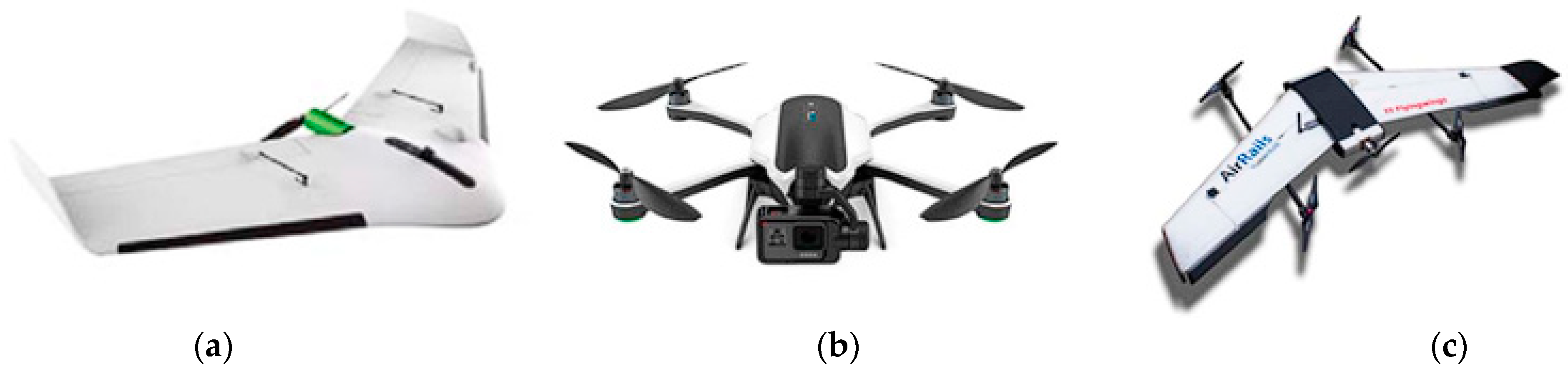
| (a) | ||||||||
| Fixed-Wing (eBee and Sky Walker X8) [9] | Airfoils type: MH44, MH45, MH60, MH64, S-5010, and Eh2.0/10.0 | Design and analysis of wing section by CFD | Aerial mapping, military, rescue, agriculture | CATIA, SOLIDWORKS, SST k-omega | Expanded polypropylene | 2D modeling, numerical drag/lift force calculations | Drag/lift coefficients computed successfully | - |
| Ranger, TUAV [10] | Frame Dimension: 4.60 × 5.70 × 1.13 m | Aerodynamic behavior and CFD analysis | Surveillance and system assault | ANSYS ICEM, ANSYS CFX | - | CFD analysis at Mach 0.1 and 0.19 numbers | Lift and drag calculations validated | Additional testing on UAV models at different velocities |
| ATLAS II [11] | Weight: 3.06 kg, Take-off load: 14 kg, Airfoils type: NACA0012, NACA0015 | Aerodynamics and flight stability analysis | - | CATIA, ANSA, ANSYS FLUENT | - | Flight mechanics drag coefficient calculations | Successful aerodynamic performance assessment | - |
| PoliDrone [12] | Weight: 2 kg, Airfoils type: S3A-C, S4A-C, S6A-C, S8A-C | Architecture and performance optimization | Aerial photography, surveillance, inspection | SOLIDWORKS, XcopterCalc, MSC Nastran, and Patran | PLA | Classical lamination theory analysis | Customization enables UAV performance variation | Further analysis of frame mechanical response |
| Twin Wing-Tail Boom [13] | Max take-off load: 105 kg, Max payload: 20 kg, Flight duration: 3–4 hr | Design and aeroelastic analysis using FEM | High altitude, high-risk areas, combat applications | MSC NASTRAN | Composite | Composite cylinder assemblage modeling | Flexible tail introduced new flutter modes | - |
| (b) | ||||||||
| Quadcopter [14] | Frame Dimension: 24 × 25 × 10 cm | Impact of airflow on frame and propeller | Agriculture, security, medical, inventory | Ansys Fluent, Autodesk Inventor | Propeller: Plastic, Frame: PLA-PLUS | CFD analysis, stress-strain calculations | Deformation issue solved with acrylic reinforcement | - |
| DJI Spark [15] | Frame Dimension: 101.25 cm × 52.5 × 34.6 cm, Angular velocity: 12,000 rpm | Aerodynamic performance of propellers | Film making, military, mining, logistics | SOLIDWORKS, SIMSCALE, SST k-omega turbulence model | - | Computation domain setup, mesh refinement | Winglet design increases thrust at the same speed | Noise level measurement for propeller blade designs |
| DJI Phantom 3 [16] | Rotor dia.: 240 mm, Angular velocity: 9549.9 rpm | Ground proximity effect and obstacle interaction | Cargo delivery, surface inspection | k-epsilon, ANSYS | - | Boundary conditions applied, mesh generation | Lift increases, drag decreases, forward pitch movement amplified | Broader range of translational velocities required |
| DJIS900 [14] | Weight: 3.3 kg, Take-off load: 8 kg | Structural investigation using atomistic simulation | Atmospheric pollution detection | GROMACS, NASTRAN | Polystyrene, composites | Molecular dynamic simulations | Weight savings of 7 g per propeller achieved | Further topological optimization needed |
| Octocopter [17] | Weight: 20 kg, Radius of rotor blade: 230 mm, Rotor velocity: 4500 rpm | Aerodynamic efficiency and CFD analysis | Battlefield surveillance, law enforcement, border patrol | ANSYS FLUENT | - | Reynolds Averaged Navier–Stokes equations | Large rotors improve aerodynamics but lower efficiency | Further optimization of rotor interaction |
| Syma X8C [18] | Weight: 0.6 kg, Rotor dia.: 240 mm, Angular velocity: 4000 rpm | Simulation of rotor separation distance | Military operations | X-FLOW | - | Lattice Boltzmann Method CFD | Rotor separation significantly affects forces | - |
| (c) | ||||||||
| Tilt-Rotor (Bell Eagle Eye, NUAA tilt-rotor, Panther UAV) [7] | Multiple rotors mounted on tilting shafts or nacelles | Investigate control stability and transition mechanisms | Surveillance, tactical operations, commercial UAVs | MATLAB, Simulink, CFD tools | Composite materials, lightweight alloys | Experimental testing, control law validation, simulation-based analysis | Hybrid UAVs improve flight stability and versatility | Structural complexity, optimization of control strategies |
| Tilt-Wing (HARVee, AVIGLE, Greased Lightning VTOL Drone, DHL Parcelcopter) [7] | Partial or entire wing tilts along with rotors | Study aerodynamic performance and transition robustness | Parcel delivery, cargo transport, research UAVs | MATLAB, Simulink, wind tunnel analysis | Carbon fiber, polymer-based materials | Aerodynamic analysis, control mechanism testing, flight trials | Tilt-wing UAVs offer good aerodynamic efficiency but face stability issues | Crosswind vulnerability, refining transition mechanisms |
| Rotor-Wing (THOR, X-50 DragonFly, NRL Stop-Rotor Aircraft) [7] | Rotary wing that spins for lift and stops for cruise | Explore feasibility of stop-rotor transition technology | Advanced aviation concepts, experimental UAVs | Navier–Stokes solvers, Computational Fluid Dynamics (CFD) | High-strength composites, carbon fiber | Hybrid modeling, wind tunnel testing, prototype development | Rotor-wing UAVs require further research for stable flight transition | High complexity, need for robust transition control strategies |
| Dual-System (HADA, Quadcruiser, Arcturus JUMP, Hybrid Quadcopter) [14] | Two sets of propulsion systems for vertical and cruise flights | Enhance mechanical simplicity and reliability | Military and civilian hybrid UAV applications | Flight simulation tools, CFD analysis | Lightweight metals, hybrid composites | Comparative analysis, aerodynamic testing, flight validation | Dual-system UAVs show promise but need optimization for efficiency | Additional weight, optimizing aerodynamic drag |
| MTT (Mono Thrust Transitioning) (SkyTote, Flexrotor, V-Bat) [7] | Single rotor at nose or rear side for thrust generation | Improve stability and efficiency of stall-and-tumble maneuver | Reconnaissance, remote monitoring | MATLAB, gain-scheduling control models | Ducted-fan composite, lightweight polymers | Simulation-based flight control validation, experimental testing | MTT UAVs face stability issues but show potential for optimized control | Unstable vertical flight, needs robust control algorithms |
| CTT (Collective Thrust Transitioning) (T-Wing, VD200, SUAVI) [7] | Single or multiple fixed-pitch non-cyclic blade rotors | Analyze aerodynamic control for forward flight | Military and industrial applications | MATLAB, nonlinear controllers, backstepping approach | High-performance composites, reinforced polymers | Hybrid modeling, dynamic inversion techniques, adaptive control | CTT UAVs provide efficient forward flight but require enhanced control mechanisms | Difficult landing, needs better tail landing mechanisms |
| DTT (Differential Thrust Transitioning) (ATMOS-UAV, VertiKUL, Google Project Wing) [7] | Rotors installed above and below the horizontal plane for transition | Develop improved transition techniques using differential thrust | Scientific exploration, experimental UAV research | MATLAB, quaternion-based control simulations | Aerodynamic composite materials | Mathematical modeling, differential thrust validation, experimental trials | DTT UAVs offer simplified control but face aerodynamic inefficiencies | Reduced efficiency in horizontal flight, needs better differential thrust modeling |
| Advantages of Composites | Disadvantages of Composites |
|---|---|
| Lightweight—Enables better flight efficiency, increased payload capacity, and lower energy consumption. | High Cost—Manufacturing and raw materials (e.g., carbon fiber) are more expensive than metals. |
| Corrosion Resistance—Composites are immune to rust and oxidation, unlike metals. | Difficult to Recycle—Most thermoset composites cannot be easily reprocessed, unlike metals such as aluminum. |
| High Fatigue Resistance—Long lifespan under cyclic loading, reducing maintenance frequency. | Impact Sensitivity—Brittle behavior under hard landings or collisions, leading to micro-cracks. |
| Design Flexibility—Can be molded into complex aerodynamic shapes with reduced assembly requirements. | Complex Manufacturing—Requires specialized fabrication methods like autoclave curing or resin transfer molding (RTM). |
| Reduced Radar Signature—Some composites have low radar reflectivity, beneficial for stealth applications. | Thermal Limitations—Degrades under high temperatures; needs special coatings for heat resistance. |
| High Strength-to-Weight Ratio and Stiffness-to-Weight Ratio—Provides structural efficiency superior to most metals. | UV and Moisture Sensitivity—Some composites degrade when exposed to prolonged sunlight or humidity. |
| Low Thermal Expansion—Enhances dimensional stability in varying temperatures, useful for UAVs in high altitudes. | Bonding Challenges—Composite-to-metal bonding can be unreliable, requiring advanced adhesive techniques. |
| Material | Density (tn/m3) | Tensile Strength (MPa) | Tensile Modulus (GPa) |
|---|---|---|---|
| GG285P(T700)-DT120-40 | 1.57 | 800 | 67 |
| GG300P(T800)-DT120-40 | 1.57 | 850 | 67 |
| PVC foam | 0.075 | 1.89 | 0.075 |
| Component | Commonly Used Materials | Key Properties | Advantages of Using These Materials for This Component | Disadvantages of Using These Materials for This Component | UD/Weave/Stacking Sequence | Matrix | Core |
|---|---|---|---|---|---|---|---|
| Fuselage | Carbon Fiber Composites, Kevlar®, Glass Fiber Composites, Aluminum | Lightweight, High Stiffness, Impact Resistant, Fatigue Resistant | Enhances UAV durability, reduces weight for improved efficiency, absorbs impact well, resists fatigue failure | High cost of composites, complex manufacturing processes, and challenging repairs if structural damage occurs | Unidirectional (UD) and woven fabrics | Epoxy | N/A |
| Wings | Carbon Fiber Composites, Glass Fiber/Nomex® Resin, Foam Core Composites, Aluminum | Aerodynamic Efficiency, High Stiffness-to-Weight Ratio, Durability | Optimizes lift-to-drag ratio, improves efficiency, reduces weight while maintaining strength | Expensive materials, complex to manufacture, and prone to micro-cracking under repeated stress | Woven fabric, Quasi-isotropic layup | Epoxy | Foam Core |
| Tail | Carbon Fiber Composites, E-Glass Epoxy, Rohacell® Foam, Aramid Honeycomb | Structural Stability, Lightweight, Resistance to Buckling and Impact | Provides stability in flight, resists deformation under aerodynamic loads, lightweight construction improves control | Difficult to manufacture, prone to delamination if not properly bonded | Woven and Sandwich stacking | Epoxy | Rohacell® Foam, Aramid Honeycomb |
| Propellers | Carbon Fiber-Reinforced Epoxy, Glass/Kevlar® Fiber Reinforced Epoxy, Laminated Wood Core | High Stiffness, Long Service Life, Rain and Impact Resistance | Enhances aerodynamics, reduces energy consumption, provides durability for extended operational life | Vulnerable to erosion (especially in rain and debris impact), expensive materials, requires maintenance | UD fiber orientations | Epoxy | Laminated Wood Core |
| Support Frame | Carbon Composite Pipe Chassis, High-Strength Nylon, Aluminum | Structural Integrity, Load Distribution, High Strength | Provides strong foundation for UAV, reduces weight while maintaining structural integrity, minimizes vibrations | Expensive materials, complex to assemble, potential joint weaknesses if not properly reinforced | UD and Woven | Thermoplastic and Epoxy | N/A |
| External Skin | Low-Radar-Profile Carbon Composites, Glass Fiber/Nomex® Resin, Polyamide-based Glass Reinforced Composites | Lightweight, Radar Absorption, Corrosion Resistance | Improves stealth properties (low radar cross-section), corrosion-resistant, resists environmental degradation | Difficult to repair, high production costs, UV degradation over time | Quasi-isotropic layup | Epoxy | Nomex® Honeycomb |
| Internal Structure | Aluminum, Carbon Fiber Composites, Epoxy Resin Composites | High Load-Bearing Capacity, Structural Rigidity, Impact Resistance | Provides strong internal framework, withstands flight loads, ensures overall UAV structural stability | Heavier compared to composite alternatives, metals are prone to corrosion if not treated | Woven fabric layup | Epoxy | N/A |
| Parts | Material | Input Weight (gm) | Manufacturing Process | Refs. |
|---|---|---|---|---|
| FWUAV-Body and wings | EPS | 1050 | Injection moulding | [45] |
| MRUAV-body + legs + Propellers | PC | 175 + 42 + 35 = 252 | Injection moulding | [45] |
| GANEFLY MAV wing, Tail, and Body | Styrofoam | 0.76 + 1.20 + 0.92 = 2.88 | Injection moulding (assumed) | [22] |
| Cowling | ABS | 284 × 262 × 141 mm (dimension) | − | [23] |
| RPA frame | High-strength nylon | 282 | Extrusion (assumed) | [38]. |
| RPA propellers | Plastic ABS | 10 × 4.5 inches (dimension) | Injection moulding (assumed) | [38]. |
| Base and Top Plate + Rotor Arms (x4) + Canopy | PET | 39.88 + 111.52 + 38.7 = 190.1 | Printing (78 h 25 min) | [25] |
| Body 1700 mm | Kevlar®, Microglass, Fiberglass, epoxy | Total weight 3800 (1266 estimate) | VARTM | [26] |
| Wing 3400 mm | Balsa core, Fiberglass | 3800 (2533 estimate) | VARTM | [26] |
| Propeller + Frame | − | 10 + 500 = 510 | − | [47] |
| Frame: | Aluminium Alloy | − | − | [48] |
| Propeller: | Nylon (30% assumed), glass fiber (60%), carbon fiber (10% assumed) (APC 1047) | 100–300 | Pultrusion process | [48] |
| Parts | Materials | Extraction and Production Energy (MJ/kg) | Manufacturing Process | Manufacturing Energy (MJ/kg) | Total Energy per kg (MJ/kg) | Ref. |
|---|---|---|---|---|---|---|
| Body | EPS | 90 | Injection Moulding | 19 | 109 | [45] |
| PC | 112.95 | 131.95 | [45] | |||
| PET | 82.71 | |||||
| Frame | Aluminium | 226.5 | − | − | − | [48] |
| Nylon | 157.65 | Injection moulding | 19 | 176.65 | [38,49] | |
| Polyester | 70.5 | 89.5 | [50] | |||
| Polystyrene | 94.5 | 113.5 | [50] | |||
| CFRC | − | RTM | − | 701 | [51] | |
| Propellors | PC | 112.95 | Injection Moulding | 19 | 131.95 | [45] |
| Composite (Nylon (30% assumed), glass fiber (60%), carbon fiber (10% assumed) (APC 1047) | 157.65, 22.5, 78 | Pultrusion process | 3.1 | 87.34 | [48,49,51,52,53] | |
| Carbon fiber-reinforced composites | − | RTM | − | 701 | [51] | |
| ABS | 105 | Injection Moulding | 19 | 124 | [38,54] |
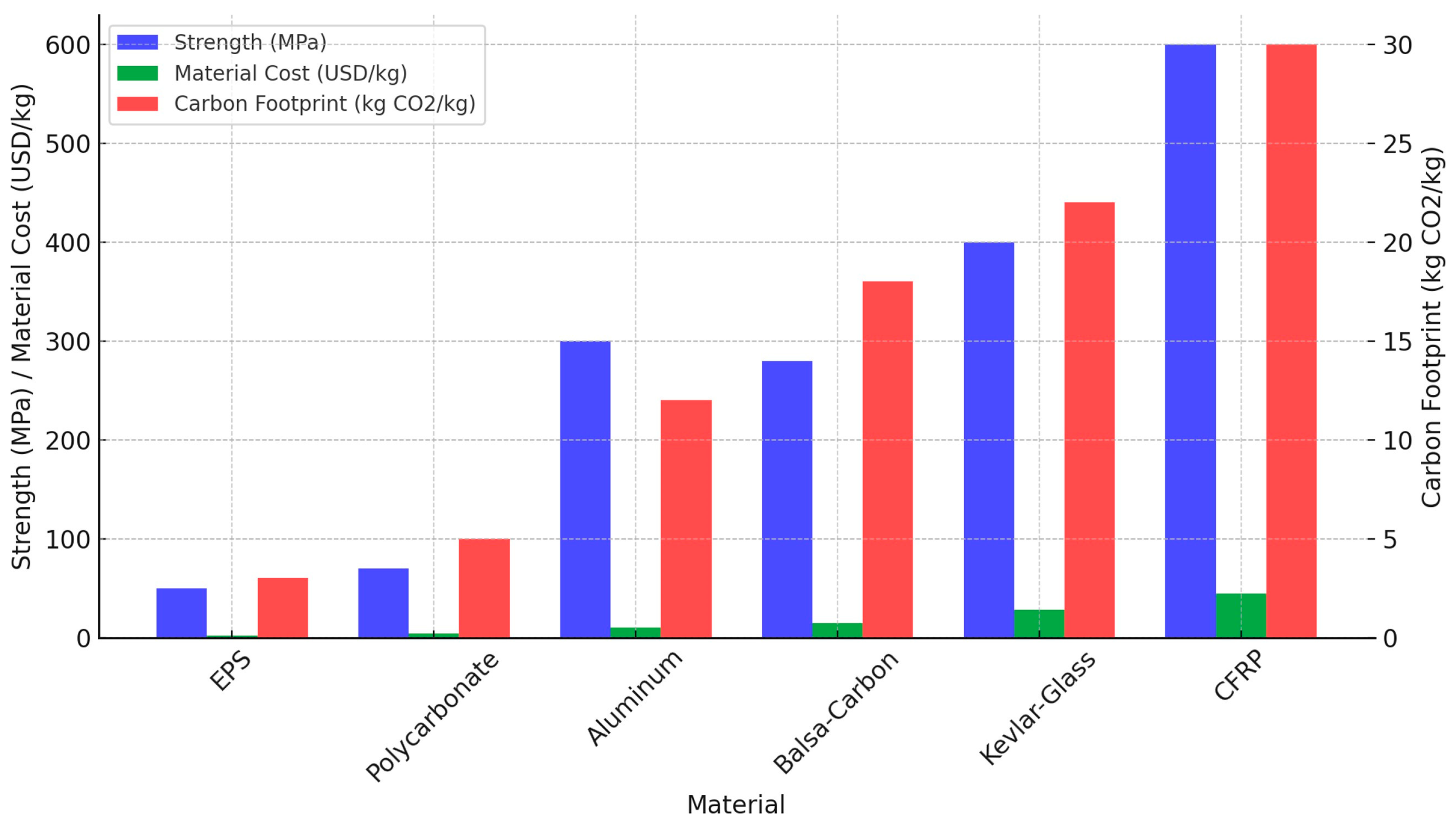
| Component | Selected Material | Strength (MPa) | Weight (kg/m2) | Carbon Footprint (kg CO2/kg) |
| Frame | Aluminum | 310 | 2.7 | 11.5 |
| Propeller | PC | 75 | 1.2 | 5.2 |
| Body | EPS | 50 | 0.5 | 3.0 |
| Wings | Kevlar®–glass | 400 | 1.5 | 22.8 |
| Uav Application | Primary Material Concerns | Environmental Hotspots in LCA | Potential Sustainable Alternatives |
|---|---|---|---|
| Delivery Drones (logistics) | CFRP, Li-ion Batteries | High embodied energy in battery production, e-waste concerns | Solid-state batteries, recycled CFRP |
| Surveillance Drones | CFRP, Aluminum, Titanium | Energy-intensive metal refining, limited CFRP recyclability | Bio-composites, lightweight alloys |
| Agricultural Drones | CFRP, GFRP, Bio-composites | Chemical degradation, high maintenance | UV-resistant bio-composites |
| Military UAVs | Aramid composites, Radar-absorbing coatings | High toxicity, non-recyclable materials | Recyclable thermoplastic composites |
Disclaimer/Publisher’s Note: The statements, opinions and data contained in all publications are solely those of the individual author(s) and contributor(s) and not of MDPI and/or the editor(s). MDPI and/or the editor(s) disclaim responsibility for any injury to people or property resulting from any ideas, methods, instructions or products referred to in the content. |
© 2025 by the authors. Licensee MDPI, Basel, Switzerland. This article is an open access article distributed under the terms and conditions of the Creative Commons Attribution (CC BY) license (https://creativecommons.org/licenses/by/4.0/).
Share and Cite
Vedrtnam, A.; Negi, H.; Kalauni, K. Materials and Energy-Centric Life Cycle Assessment for Drones: A Review. J. Compos. Sci. 2025, 9, 169. https://doi.org/10.3390/jcs9040169
Vedrtnam A, Negi H, Kalauni K. Materials and Energy-Centric Life Cycle Assessment for Drones: A Review. Journal of Composites Science. 2025; 9(4):169. https://doi.org/10.3390/jcs9040169
Chicago/Turabian StyleVedrtnam, Ajitanshu, Harsha Negi, and Kishor Kalauni. 2025. "Materials and Energy-Centric Life Cycle Assessment for Drones: A Review" Journal of Composites Science 9, no. 4: 169. https://doi.org/10.3390/jcs9040169
APA StyleVedrtnam, A., Negi, H., & Kalauni, K. (2025). Materials and Energy-Centric Life Cycle Assessment for Drones: A Review. Journal of Composites Science, 9(4), 169. https://doi.org/10.3390/jcs9040169