Article

Study on Dynamic Response of Damping Type Composite Floor Slabs Considering Interlayer Interaction Influences

1
School of Civil Engineering and Architecture, Wuhan University of Technology, Wuhan 430070, China
2
China Construction Third Engineering Group Co., Ltd., Xi’an 710066, China
3
Power China Hubei Electric Engineering Co., Ltd., Wuhan 430070, China
4
Centre for Infrastructure Engineering and Safety, School of Civil and Environmental Engineering, The University of New South Wales, Sydney, NSW 2052, Australia
5
School of Civil and Environmental Engineering, University of Technology Sydney, Sydney, NSW 2007, Australia
*
Author to whom correspondence should be addressed.
J. Compos. Sci. 2025, 9(2), 57; https://doi.org/10.3390/jcs9020057
Submission received: 21 December 2024 / Revised: 17 January 2025 / Accepted: 22 January 2025 / Published: 26 January 2025

Abstract

:
In order to explore the vibration mechanism of vibration damping composite floor slabs and further enrich the theory of floor slab vibration calculation, the free vibration characteristics of vibration damped composite floor slabs and the dynamic response of vibration damped composite floor slabs under multi-source excitation is analyzed using first type Chebyshev polynomials to construct the displacement function and derive an analytical solution. The three-dimensional laminated theory is employed, considering the interlayer interaction. Based on the proposed method, the influences of loading types, positions, magnitudes, and frequencies on the vertical vibration of floor slabs are calculated. The study illustrates that, under the action of multi-source excitation, the displacement and acceleration responses calculated by the method proposed in this paper are always greater than those calculated by the single-plate theoretical solution. The dynamic responses of the vibration damping composite floor slab decrease with the increase of the thickness and elastic modulus of the vibration damping layer. Under different thicknesses of the vibration damping layer, the peak accelerations of the vibration damping composite floor slabs increase linearly with the growth of the load amplitude. In addition, the load movement path has a significant effect on the vibration response of the floor slab. When the moving load moves along the short side of the floor, the displacement response of the floor is generally greater than that along the long side of the floor.

1. Introduction

With the development of technology and industry, the demand for precise instrument plants have increased. Meanwhile, the requirements for equipment accuracy are largely improved. As a result, multi-source vibration control has become the most important topic in plant construction. External excitation sources (highways and rail transit) and internal excitation sources (equipment vibration, moving vehicles and personnel walking) are usually combined and lead to floor vibration, which seriously interfere the normal operation of precision instruments [1]. As an important part of a building, the floor slabs play a major role in the propagation of vertical vibration of the structure. Therefore, the stiffness and elastic modulus of the floor slabs have a direct impact on the overall dynamic mechanical performance of the building structure.
Researchers have investigated the influence of non-structural layers, such as damping layers and decorative layers, on the vibration responses of floors through numerical simulation or experimental methods. At present, some useful numerical models and simulation approaches have been established for blank cross-laminated panels, concrete slabs, and floors with decorative layers [2,3,4]. Zhai et al. [5] established an equilibrium equation of the damping layer composite plate based on the traditional plate theory, and then studied the influence of the thickness of the damping layer on the free vibration of the composite plate by numerical simulation methods. Hu et al. [6] proposed the vibration governing equations and the general elastic boundary equations of arbitrary rectangular composite laminates based on the first-order shear deformation theory. In order to derive the dynamic equations of corrugated sandwich panels, their fundamental frequencies under four boundary conditions were calculated and compared using the five-plate theory and Hamilton’s principle [7]. The modal characteristics of two full-scale floors with the same structure in an actual decorative building were also measured to study the influence of non-structural cladding and partition walls on the vertical vibration response of building floors [8].
Excitation sources can also generate different vibration responses on floor slabs. For human-induced loads, some scholars developed an equation to evaluate the dynamic performance of large-span floor structures under crowd loads. The four-element plate model is used to study the vibration behavior of special-shaped steel bridge deck composite slabs under human walking and rhythmic activities [9,10]. For vehicle loads, a binary brittleness evaluation model considering both vehicle weight and moving speed is used to investigate the micro-vibration of large-span floors caused by internal moving vehicles or automated guided vehicles (AGVs) in high-tech manufacturing plants [11]. An equivalent model was established to effectively analyze the vibration of the prefabricated structure of multi-layer profiled steel sheet–concrete composite floor slabs (PSSCCFs) induced by high-speed trains. Additionally, three composite floor slab models with the same dimensions but with different materials were established. The vibration response laws of the floor slabs under the action of train excitation were analyzed, and the differences in the responses among the three were compared [12,13]. For other loads, Ju et al. [14] established a finite element model to simulate the vibration caused by the crane on the floor of a high-tech factory. The contact element was introduced, and the vibration response of the reinforced concrete composite slab was analyzed by numerical simulation [15,16,17]. However, the above-mentioned study fails to consider the superposition effect of various loads. Moreover, the impact of these loads on the vertical vibration of the floor slab varies significantly with respect to position, magnitude, and frequency, among other factors.
In summary, previous research has predominantly focused on the vibration response of ordinary building floors, such as concrete slabs and reinforced concrete composite slabs. For floors with non-structural layers, the current theory usually simulates the influence of non-structural layers by increasing the slab thickness according to the equivalence principle, whereas it ignores the interlayer interactions caused by the different material properties of structural and non-structural layers in composite floors. Regarding the theoretical derivation of the vibration response of the floor system, the existing research only focuses on the free vibration, or the vibration induced by single excitation [18,19,20,21,22]. In the real condition, the concrete floors are simultaneously excited by human loads, vehicle loads and machine loads. Therefore, it is of great practical significance to consider the interaction between layers and solve the dynamic response of damping composite floor slabs under multi-source excitation.
In this study, a vibration damping composite floor is taken as the research object, and its vibration response is studied by the spectral method. The displacement variables of the vibration damping composite floor slab are expanded into the first type Chebyshev polynomial and double trigonometric series, based on the three-dimensional laminated theory and considering the influence of interlayer interactions. The displacement function is constructed using the first type of Chebyshev polynomial. The analytical solution for the free vibration characteristics of vibration damped composite floor slabs and the dynamic response of the vibration damped composite floor slabs under multi-source excitation is derived. The material of the vibration reduction layer is considered as the flexible vibration reduction layer and the rigid vibration reduction layer selected in the actual project. This study analyses the impact of various parameters, including the thickness and elastic modulus of the vibration damping layer, as well as the load position on the dynamic response of composite floor slabs caused by multi-source excitation. Numerical examples are used to demonstrate the findings, which can be used as a reference for designing floor slabs with effective vibration reduction.

2. Theoretical Derivation of Vibration

2.1. Analysis Model

Researchers usually use simplified models to study the vibration responses of vibration damped composite floor slabs. For example, Lu et al. [23] developed isotropic and orthogonal anisotropic equivalent calculation models for composite floor slabs by applying the principles of displacement and stiffness equivalence. However, they oversimplified the composite floor slab by treating it as a single-layer slab and ignored the influence of interlayer interaction. To address this limitation, this research takes into account the inter-layer vibration and the equivalent vibration damping composite floor slab to a three-dimensional laminated floor slab model. This composite floor slab is composed of multiple single layers with different thicknesses and material properties, and these layers are connected in a co-node manner, as illustrated in Figure 1. The model and coordinate system for the vibration damped composite floor slab are presented; the dimensions of the vibration damped composite floor slab along the x, y, and z directions are denoted as a, b, and h for length, width, and thickness, respectively. The Cartesian coordinate system is situated on the geometric bottom surface of the structure. The material parameters of the composite floor slab are taken according to the actual floor parameters, as follows: a = 7.2 m and b = 4 m. In the parameter analysis, the thickness of the structural layer varies among 0.08 m, 0.10 m, and 0.12 m; the thickness of the vibration damped layer ranges from 0 to 100 mm; and the thickness of the decorative layer is 20 mm.

2.2. Free Vibration Theory

Based on the three-dimensional lamination theory, when the composite floor slab undergoes small deformations, the basic strain–displacement relationship of the k-th layer is expressed as follows:
ε x k = δ u k δ x , ε y k = δ v k δ y , ε z k = δ w k δ z . γ y z k = δ v k δ z + δ w k δ y , γ x z k = δ u k δ z + δ w k δ x . γ x y k = δ v k δ x + δ u k δ y .
where ε x k , ε y k and ε z k represent the normal strain component and γ y z k , γ x z k and γ x y k represent the shear strain component.
In an orthogonal coordinate system, for linearly elastic bodies and anisotropic materials, the stress components related to the six strain components are written using the three-dimensional constitutive equations as follows:
σ x σ y σ z τ y z τ z x τ x y = C ¯ 11 C ¯ 12 C ¯ 13 C ¯ 14 C ¯ 15 C ¯ 16 C ¯ 21 C ¯ 22 C ¯ 23 C ¯ 24 C ¯ 25 C ¯ 26 C ¯ 31 C ¯ 32 C ¯ 33 C ¯ 34 C ¯ 35 C ¯ 36 C ¯ 41 C ¯ 42 C ¯ 43 C ¯ 44 C ¯ 45 C ¯ 46 C ¯ 51 C ¯ 52 C ¯ 53 C ¯ 54 C ¯ 55 C ¯ 56 C ¯ 61 C ¯ 62 C ¯ 63 C ¯ 64 C ¯ 65 C ¯ 66 ε x ε y ε z γ y z γ z x γ x y = C k ε k .
When the above-mentioned material is an isotropic material, the stiffness matrix is defined as follows:
C k = C 11 C 12 C 13 0 0 0 C 21 C 22 C 23 0 0 0 C 31 C 32 C 33 0 0 0 0 0 0 C 44 0 0 0 0 0 0 C 55 0 0 0 0 0 0 C 66 .
Among these, the stiffness coefficients can be calculated by the following formulas:
C 11 = C 22 = C 33 = E 1 υ 1 2 υ 1 + υ . C 12 = C 21 = C 13 = C 31 = C 23 = C 32 = υ E 1 2 υ 1 + υ . C 44 = C 55 = C 66 = 1 2 C 11 C 12 .
where E represents the elastic modulus of the material of a certain layer of the building composite floor slab and υ represents the Poisson’s ratio of the material of a certain layer of the building composite floor slab.
For the vibration analysis of composite structures based on the energy variational method, the construction of the admissible displacement function often determines the convergence rate and solution accuracy of the vibration analysis. It has been proved that Chebyshev polynomials exhibit excellent stability convergence properties when using three-dimensional theory to calculate the behavior of elastic plates. For example, Zhou [24] used the first-class Chebyshev polynomial to establish the displacement function and analyze the free vibration of elastic plates with different thicknesses. It was found that the calculation results converged quickly and that the calculation accuracy was acceptable. The first type of Chebyshev polynomial is defined as follows for any integer n > 0:
T n x = n 2 i = 0 n / 2 1 i n i 1 ! i ! n 2 i ! 2 x n 2 i .
where [n/2] represents the maximum integer not greater than n/2.
The first kind of Chebyshev polynomials satisfy the following recurrence relation on the interval [−1, 1]:
T 0 x = 1 , T 1 x = x , T n + 1 x = 2 x T n x T n 1 x , n 1 .
By introducing the variables ξ = 2z/h − 1, we can redefine the first type of shifted Chebyshev polynomial. The first type of Chebyshev polynomial with an action interval of [0, h] can then be expressed as:
z 0 , h , ξ 1 , 1 , ξ = 2 z h 1 , T 0 ξ = 1 , T 1 ξ = 2 z h 1 , T n ξ = n 2 i = 0 n / 2 1 i n i 1 ! i ! n 2 i ! 4 z h 2 n 2 i .
T n ξ is an orthogonal polynomial with respect to the weight function ω x = ( 1 x 2 ) 1 2 in the interval [−1, 1], and satisfies the following relationship:
T n , T m = 1 1 T n ( x ) T m ( x ) 1 x 2 d x = 0 ,      n m π 2 ,     n = m 0 π ,      n = m 0 .
According to the spectral method, the displacement function for the k-th layer is expressed as a product of trigonometric functions and an expansion of the first type Chebyshev polynomial. The displacement function can be represented as follows:
u k x , y , ξ , t = m = 1 M n = 1 N r = 0 R u k m n r t cos m π x a sin n π y b T r ξ = u i k U 2 , v k x , y , ξ , t = m = 1 M n = 1 N r = 0 R v k m n r t sin m π x a cos n π y b T r ξ = v i k V 2 , w k x , y , ξ , t = m = 1 M n = 1 N r = 0 R w k m n r t sin m π x a sin n π y b T r ξ = w i k W 2 .
where,
U 2 = cos ( 1 · π x a ) sin ( 1 · π y b ) cos ( 0 · arccos ξ ) , , cos ( M · π x a ) sin ( N · π y b ) cos ( R · arccos ξ ) , V 2 = sin ( 1 · π x a ) cos ( 1 · π y b ) cos ( 0 · arccos ξ ) , , sin ( M · π x a ) cos ( N · π y b ) cos ( R · arccos ξ ) , W 2 = sin ( 1 · π x a ) sin ( 1 · π y b ) cos ( 0 · arccos ξ ) , , sin ( M · π x a ) sin ( N · π y b ) cos ( R · arccos ξ ) .
The Rayleigh–Ritz method, which is based on the principle of energy, is used in this research to solve unknown coefficients. The energy function for constructing a vibration damped composite floor slab is determined according to Hamilton’s variational principle [25]:
Π T o l = t 0 t 1 k = 1 3 T k U k + W k d t .
where Uk represents the strain energy of the k-th layer of the system, Tk represents the total kinetic energy of the k-th layer of the system, and Wk represents the work done by external excitation on the k-th layer of the plate.
According to the three-dimensional lamination theory, the strain energy, kinetic energy and work done by external forces of the k-th layer can be expressed as:
U k = 1 2 V σ k x ε k x + σ k y ε k y + σ k z ε k z + τ k x y γ k x y + τ k x z γ k x z + τ k z y γ k z y d V . T k = 1 2 V ρ k u ˙ 2 k + v ˙ 2 k + w ˙ 2 k d V . W k = A f x u k + f y v k + f z w k d A .
where σ k x , σ k y , σ k z , τ k x y , τ k x z , τ k z y represents the stress component of the k-th floor slab; ε k x , ε k y , ε k z , γ k x y , γ k x z , γ k z y represents the strain component of the k-th floor slab, and V1 is the volume of the floor slab. uk, vk and wk represent the displacement components along the x, y, and z axes, respectively, at a point on the k-th layer. Their time derivatives u · k , v · k and w · k respectively represent the velocity component of a point on the k-th layer along the x, y and z axes, ρk is the density of the k-th floor slab. A represents the surface area of the floor slab level.
Substitute Equations (9) and (12) into Equation (11) and expand. Then, set the variations of the energy functional with respect to all of the expansion coefficients of the displacement function to zero, thus obtaining the characteristic equation of the composite floor slab:
K ω 2 M q = 0 .
where q represents the generalized displacement of the composite floor slab, M and K represent the mass matrix and stiffness matrix of the composite floor slab, respectively, and ω represents the natural frequency of the composite floor slab. The expressions of the above-mentioned generalized displacement, mass matrix, stiffness matrix and their respective elements are as follows:
q = u 1 110 , , u 2 110 , , u 3 110 , , w 3 M N R T .
K = diag [ K 1 , K 2 , K 3 ] ,   M = diag [ M 1 , M 2 , M 3 ] .
K k = K k u u K k u v K k u w K k v u K k v v K k v w K k w u K k w v K k w w , M k = M k u u 0 0 0 M k v v 0 0 0 M k w w .
The detailed expressions of the elements of the above-mentioned mass matrix and stiffness matrix are given in Appendix A.

2.3. Dynamic Response Solution

This study simplifies machine loads as fixed harmonic loads and mobile transport vehicles as moving loads. The vibration damped composite floor slab is assumed to have an amplitude of P1 and a frequency of ω1 at point H1 (x1, y1, z1). Simultaneously, a harmonic load of 1 with an amplitude of P2 and a moving speed of vx and vy along the x and y directions, respectively, is applied at point H2 (x2, y2, z2). z1 = z2 = h. The load P(t) is defined as follows:
P t = P 1 δ x x 1 δ y y 1 δ z h sin ω 1 t + P 2 δ x x 2 v x t δ y y 2 v y t δ z h .
where δ is the Dirac function and the expression is δ ( x x 0 ) d x = 1 .
The fixed harmonic load and moving load can be expressed by Equation (18) and Equation (19), respectively.
P t = P 1 δ x x 1 δ y y 1 δ z h sin ω 1 t .
P t = P 2 δ x x 2 v x t δ y y 2 v y t δ z h .
By substituting Equations (12) and (17) into Equation (11), the motion equation of the vibration damped composite floor slab can be obtained:
δ t 1 t 2 k = 1 3 1 2 V 1 σ k x ε k x + σ k y ε k y + σ k z ε k z + τ k x y γ k x y + τ k x z γ k x z + τ k z y γ k z y ρ k u ˙ 2 k + v ˙ 2 k + w ˙ 2 k d V 1 A P 1 δ x x 1 δ y y 1 δ z h sin ω 1 t w 3 d A A P 2 δ x x 2 v x t δ y y 2 v y t δ z h w 3 d A d t = 0 .
When only fixed harmonic load or moving load exists, the motion equation can be expressed by Equations (21) and (22), respectively.
δ t 1 t 2 k = 1 3 1 2 V σ k x ε k x + σ k y ε k y + σ k z ε k z + τ k x y γ k x y + τ k x z γ k x z + τ k z y γ k z y ρ k u ˙ 2 k + v ˙ 2 k + w ˙ 2 k d V A P 1 δ x x 1 δ y y 1 δ z h sin ω 1 t w 3 d A d t = 0 .
δ t 1 t 2 k = 1 3 1 2 V σ k x ε k x + σ k y ε k y + σ k z ε k z + τ k x y γ k x y + τ k x z γ k x z + τ k z y γ k z y ρ k u ˙ 2 k + v ˙ 2 k + w ˙ 2 k d V A P 2 δ x x 2 v x t δ y y 2 v y t δ z h w 3 d A d t = 0 .
Substitute Equations (9) and (10) into Equation (19). Then, set the variation of all expansion coefficients of the energy functional on the displacement function zero. Finally, organize the results to obtain the following formula:
M q ¨ + K q = F .
where q represents the generalized displacement matrix of the composite floor, while M and K represent the mass matrix and stiffness matrix of the composite floor, respectively, and F represents the generalized force matrix. The following expressions respectively represent the generalized displacement matrix, mass matrix, stiffness matrix, and generalized force matrix:
q = u 1 110 , , u 2 110 , , u 3 110 , , w 3 M N R T ,
K = diag [ K 1 , K 2 , K 3 ]   ,   M = diag [ M 1 , M 2 , M 3 ]   , F = diag [ 0 , 0 , F 3 ] ,
K k = K k u u K k u v K k u w K k v u K k v v K k v w K k w u K k w v K k w w , M k = M k u u 0 0 0 M k v v 0 0 0 M k w w , F 3 = 0 0 F t .
Appendix A presents detailed expressions for each element in the quality matrix and stiffness matrix. In this section, we only provide the detailed representation of F(t) in the generalized force matrix.
F ( t ) = P 2 sin ( 1 · π ( x 2 + v x t ) a ) sin ( 1 · π ( y 2 + v y t ) b ) + P 1 sin ( 1 · π x 1 a ) sin ( 1 · π y 1 b ) sin ω 1 t · · · P 2 sin ( M · π ( x 2 + v x t ) a ) sin ( N · π ( y 2 + v y t ) b ) + P 1 sin ( M · π x 1 a ) sin ( N · π y 1 b ) sin ω 1 t .
When only fixed harmonic load or moving load is considered, the F(t) in the generalized force can be expressed by Equations (28) and (29), respectively.
F ( t ) = P 1 sin ( 1 · π x 1 a ) sin ( 1 · π y 1 b ) sin ω 1 t · · · P 1 sin ( M · π x 1 a ) sin ( N · π y 1 b ) sin ω 1 t .
F ( t ) = P 2 sin ( 1 · π ( x 2 + v x t ) a ) sin ( 1 · π ( y 2 + v y t ) b ) · · · P 2 sin ( M · π ( x 2 + v x t ) a ) sin ( N · π ( y 2 + v y t ) b ) .
Further simplifying Equation (23) as follows, similar to the motion equation of a single degree of freedom system:
m n r ( 2 q m n r t 2 + ω 2 q m n r = F m n r t M m n r ) .
Using the Duhamel integral, Equation (30) can be solved to obtain the generalized displacement expression for the i-th order, as follows:
q i t = 1 ω i M i 0 t F τ sin ω i t τ d τ = u i ( t ) v i ( t ) w i ( t ) .
To determine the displacement of the structure, substitute the aforementioned equation into Equation (9) for the structural displacement function. When calculating the displacement response of the n-order vibration mode of the composite floor slab, it is essential to compute the generalized displacement of each order of the composite floor slab and solve the displacement response separately. The overall displacement response of the composite floor slab is obtained by superimposing the displacement response of each order, as follows:
u x , y , z , t = i = 1 n u i x , y , z , t , v x , y , z , t = i = 1 n v i x , y , z , t , w x , y , z , t = i = 1 n w i x , y , z , t .
When only the fixed harmonic load is taken into account, Equation (33) represents the forced vibration response of the composite floor slab. When the load ceases to act, the composite floor slab will transition to free vibration, and its displacement response can be expressed as follows:
q x , y , z , t = q x , y , z , t 0 cos ω t t 0 + q ˙ x , y , z , t 0 ω sin ω t t 0 .
If the moving load is considered as a moving harmonic load, the load is defined as follows:
P t = P δ x x 2 v x t δ y y 2 v y t δ z h sin ω 2 t .
The expression of the displacement response corresponding to the i-th vibration mode of the composite floor slab under the action of the moving load can be directly presented as follows:
q i t = 1 ω i M i 0 t F ( τ ) sin ω i t τ sin ( ω 2 τ ) d τ = u i ( t ) v i ( t ) w i ( t ) .

2.4. Case Verification

2.4.1. Free Vibration

Taking the simplified models of multi-layer composite floor slabs under different parameters as the research objects, this paper analyzes the vibration characteristics of the floor slabs and explores the influence of inter-layer interaction on the vibration characteristics of the composite floor slabs. To simplify the research, in the subsequent calculations, Ω = ω a 2 ρ / ( E 2 h 2 ) is adopted to make the frequency of the composite floor slab dimensionless, unless otherwise specified.
Table 1 presents the first five-order dimensionless frequencies of the square composite floor slab with four-side simply supported boundaries obtained by changing the number of polynomials M × N × R required in the x, y and z directions. The data are compared with those given in [26], and the ANSYS finite element solutions using the solid element solid185 are also provided to verify the accuracy of the method proposed in this paper. Figure 2 shows the first five-order modal vibration patterns of the corresponding four-side simply supported composite floor slab. The method in this paper selects the parameter values of the examples in [26]. The length and width of the plate are both 1 m, and the thickness is 0.05 m. The elastic modulus E1 is 150 GPa and E2 and E3 are both 10 GPa. The shear moduli G12 and G13 are both 6 GPa, G23 is 5 GPa. The Poisson’s ratio is 0.25, and the material density is 1450 kg/m3.
As can be seen from Table 1, with the continuous increase of the truncation times in this paper, the frequencies of each order of the composite floor slab gradually converge to stable values from the low order to the high order. When M-N-R = 6-6-6, all dimensionless frequencies converge. Compared with the results in [26], both methods are based on the three-dimensional lamination theory. Therefore, the calculated results of the first five-order dimensionless frequencies of the two methods are highly consistent, with the error of the dimensionless frequencies not exceeding 0.104%. When compared with the finite element results, the results calculated by the method in this paper are also highly consistent with the three-dimensional finite element solutions, with the maximum error not exceeding 0.720%, demonstrating the accuracy of the method in this paper. In addition, the matrix dimension of the spectral method in this paper to reach the convergence value is 648 × 648, while the matrix dimension in [26] is 1125 × 1125. The computational amount of this paper is one-fourth of that in [26], and the computational efficiency is higher. Meanwhile, the deviation between the dimensionless frequencies with a computational amount of 6-6-5 and those with a computational amount of 12-12-6 does not exceed 0.1%. Evidently, the method in this paper also has the advantage of a fast convergence rate.

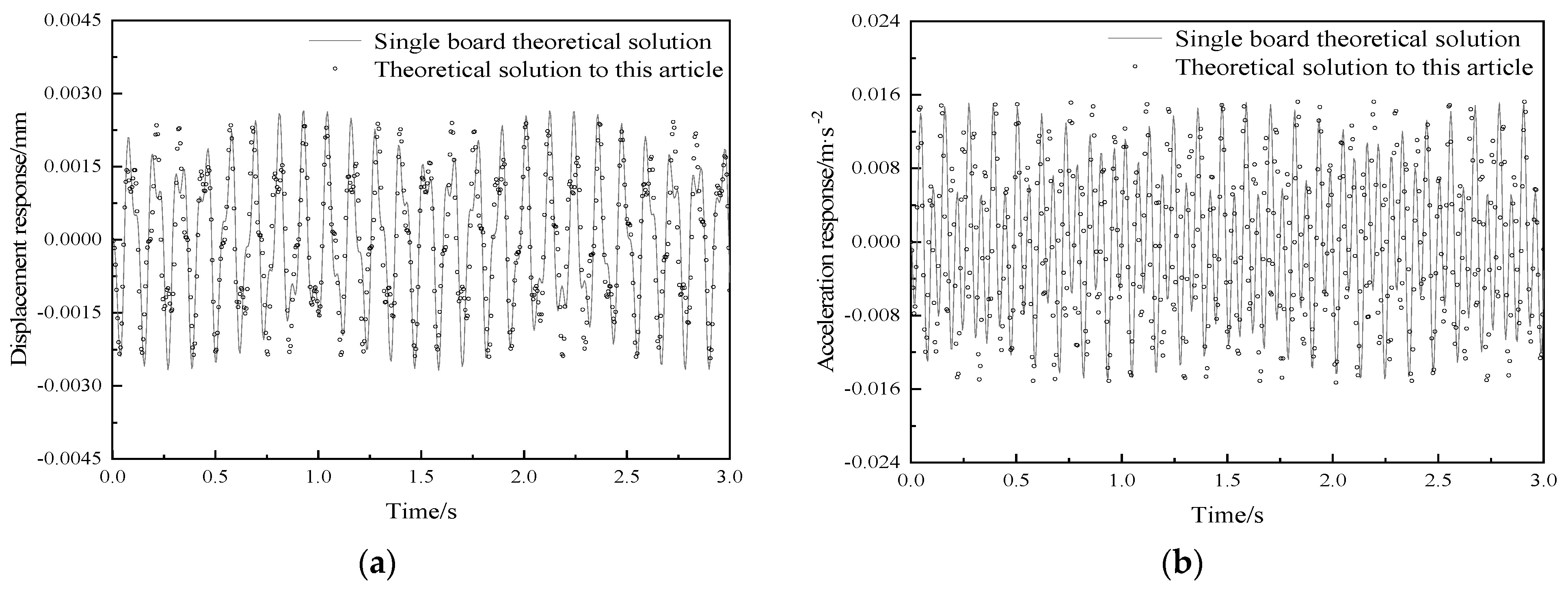
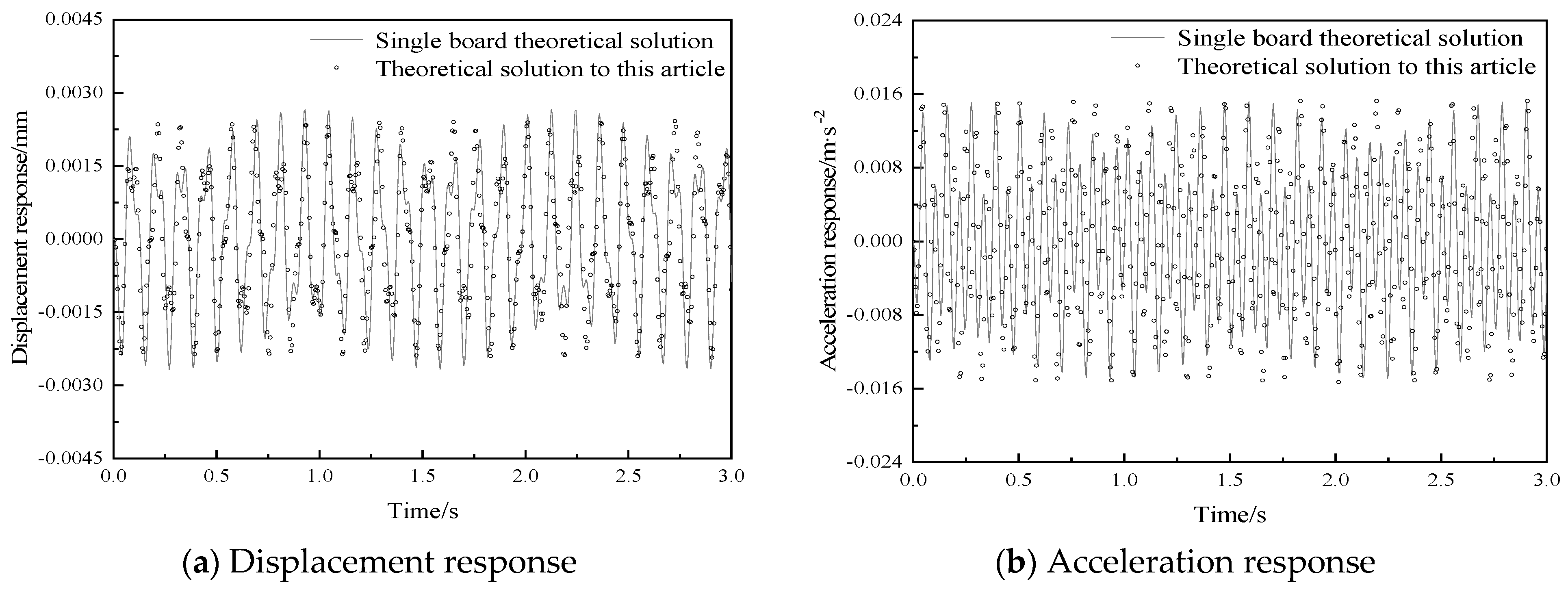
2.4.2. The Action of Fixed Loads

To verify the correctness of the analytical solution derived in this paper for the dynamic response of a vibration damping composite floor slab under multi-source excitation, the same material and parameters are adopted for each of its layers. According to the theoretical derivation in the previous section, the displacement response of the vibration damping composite floor slab model is calculated by using the method presented in this paper, and is then compared with the existing solutions of the displacement response of a single slab under various types of loads. The material parameters of the composite floor slab are taken according to the actual floor slab parameters. The size is 7.2 m × 4 m, and the structural parameters are shown in Table 2. Figure 3 shows the layout diagrams of the fixed load (P1) and the moving load (Path1).
Before calculating the dynamic response of the floor slab under harmonic loads, it is necessary to determine the frequency and amplitude of the loads. According to the Technical Standard for Vibration Serviceability of Building Floor Structures [27] (JGJ/T 441-2019), the vertical dynamic load of the electric motor can be calculated according to the following equations:
ω p = 0.105 n m , P m = m m e m ω p 2 , P m t = P m sin ( ω p t ) .
where ωp represents the working circular frequency of machinery and equipment (rad/s), nm denotes the rotational speed of the machine (r/min), Pm stands for the disturbing force of the machine (N), mm indicates the total mass of the rotating components (kg), em represents the equivalent eccentricity of the total mass of the rotating components with respect to the center of rotation (m), and Pm(t) is the vertical dynamic load of the machine (N).
In this section, the analytical solutions of the composite floor slab under the action of harmonic loads are verified based on the parameters of machinery and equipment given in [28]. The parameters of the machinery and equipment are shown in Table 3.
Based on the above-mentioned specification standards and equipment parameters, the disturbing force of the machinery and equipment is calculated. The size and structural parameters of the floor slab are shown in Table 2.
According to the steady-state solution of the dynamic response of a simply supported plate on four sides under harmonic loads, as given in [29], we find the following:
w x , y , t = m = 1 n = 1 P W m n ( x 0 , y 0 ) M m n ( ω m n 2 ω p 2 ) W m n ( x , y ) ( sin ω p t ω p ω m n sin ( ω m n t ) ) .
where Wmn represents the various vibration modes of the plate, Mmn denotes the generalized mass under each vibration mode of the plate, and ωmn stands for the natural frequencies of each order of the plate.
To simplify the calculations, only the first-order vibration mode function of the floor slab will be discussed in this section and subsequent ones. According to the analytical solution of the dynamic response provided in this paper, programming calculations are carried out using MATLAB. Figure 4 shows the time-based curves of the vertical vibration response at the center point of the floor slab under the fixed harmonic load. Table 4 presents a comparison of the peak values of the vibration response at the center point (P1) of the floor slab calculated by the single-plate theory and the method in this paper under the harmonic load, and also gives the definition of the error for this section and subsequent ones, as follows:
δ 0 z = z article z board z board × 100 % , δ 0 a = a article a board a board × 100 % .
where δ0z represents the error of the displacement peak value, δ0a represents the error of the acceleration peak value, z represents the peak value of the displacement response of the plate, and a represents the peak value of the acceleration response of the plate.
Table 1. The first five-order natural frequencies of the four-side simply supported composite floor slabs with different truncation series.
M × N × RDimensionless Frequency
f1f2f3f4f5
5-5-312.08319.70635.05640.45145.017
6-6-412.01919.60434.78339.69244.227
6-6-512.01919.60434.78239.69144.226
6-6-612.01819.59934.75039.68844.221
7-7-612.01819.59934.75039.68844.221
8-8-612.01819.59934.75039.68844.221
9-9-612.01819.59934.75039.68844.221
10-10-612.01819.59934.75039.68844.221
12-12-612.01819.59934.75039.68844.221
ANSYS12.01819.59834.72539.70044.244
Ref. [29]12.01719.59234.71439.68044.211
Table 2. Floor slab structural parameters.
Elastic Modulus/GPaDensity/kg·m−3Poisson’s RatioThickness/m
3025000.30.13
Table 3. Design parameters of machinery and equipment.
Mass
/kg
Rotational Speed of the Machine/r·min−1Equivalent Eccentricity/mLoad Amplitude/NLoad Amplitude/rad·s−1
1805000.0000839.6952.5
Table 4. Comparison of peak vibration responses at the center point of the floor slab under fixed loads.
Working ConditionPeak Displacement Response
(10−3·mm)
Peak Acceleration Response (mm·s−2)Peak Displacement ErrorPeak Acceleration Error
Theoretical solution proposed in this research2.4315.30−9.33%0.72%
Single board theoretical solution2.6815.19
As can be seen from the comparison of displacement responses and acceleration responses in Figure 4 and Table 4, when it is assumed that the materials of each floor of the floor slab are the same, under the action of harmonic loads, the results of the displacement response and acceleration response at the center point of the building composite floor slab calculated by the method in this paper are basically consistent with those calculated by the single-plate theory solution. Among them, the displacement error is −9.328%, and the acceleration peak error is even smaller, only 0.724%. The errors mainly stem from the fact that the equivalent single-layer thin-plate theory is based on the thin-plate vibration theory, overlooking the inter-layer shear and extrusion effects. The theoretical method proposed in this paper takes into account the influence of inter-layer interaction. When the composite floor slab vibrates, the inter-layer stresses between each layer of the floor slab are considered. Therefore, it can be demonstrated that the theoretical derivation in this paper is correct and effective.

2.4.3. The Action of Moving Loads

Ref. [29] presents the steady-state solution of the dynamic response of simply supported plates on four sides under the action of moving loads, as follows:
w x , y , t = m = 1 n = 1 P sin ( n π y 0 b ) M m n ( ω m n 2 ( m π v a ) 2 ) W m n ( x , y ) ( sin ( m π v a t ) m π v ω a sin ( ω m n t ) ) .
The computational model of the composite floor slab under moving loads is verified based on the parameters of the factory transport vehicle given in [30]. The size and structural parameters of the floor slab are shown in Table 2. The mass of the transport vehicle is 200 kg, which moves along the direction of the short side from the one-quarter position of the long side at a speed of 2 m·s −1 (Figure 2, Path1). Figure 5 shows the vertical vibration response at the center point of the floor slab under moving loads calculated by the single board theoretical solution and theoretical solution proposed in this research. Table 5 presents a comparison of the peak values of the vibration response at the center point (P1) of the floor slab, calculated by the single-plate theory and the method in this paper under moving loads.
From the comparison of the displacement responses and acceleration responses in Figure 5 and Table 5, it can be found that the displacement responses and acceleration responses under moving loads calculated by the method in this paper are always greater than the results of the theoretical analytical solutions simplified as single-plate calculations. Moreover, as the load gradually moves, the displacement difference increases at first and then decreases steadily. In addition, the displacements basically coincide at the edge of the plate, and the displacement error reaches its maximum at the center of the plate, as high as 47.06%. The difference of acceleration response between the two calculation methods is not obvious, and the acceleration peak error is 23.29%.
The calculation method proposed in this paper takes into account the influence of interlayer interactions. Therefore, the frequency of the floor slab calculated according to the method in this paper is lower than the frequency obtained by treating the floor slab as a single plate. It can also be seen from Equation (38) that a decrease in frequency will lead to an increase in the displacement response. One of the assumptions of the single-plate theory is that all layers are assumed to be completely bonded together, with no relative sliding, separation, or debonding between layers. This means that, when the composite plate is loaded and deformed, the displacements between layers are continuous, and the stress transfer between layers is ideal. Thus, the composite plate can be analyzed as a whole without considering the complex inter-layer interactions. However, for multi-layer composite structures, due to the small shear modulus of the structure, there are significant shear deformations. Therefore, the inter-layer interactions of multi-layer composite plates cannot be ignored. The error between the calculation results based on the method in this paper and the solutions of the single-plate theory reflects the accuracy of the three-dimensional theory in calculating the dynamic response of the floor slab. In summary, the method proposed in this paper can be considered more accurate and effective.

2.4.4. The Action of Multi-Source Excitation

The steady-state solutions of the dynamic responses of a simply supported rectangular plate on four sides under the coupled harmonic loads and moving loads can be expressed by Equation (37) and Equation (39), respectively. The load location arrangement is shown in Figure 3. A fixed harmonic load is applied at the center of the slab (Figure 3, P1), while a moving load is shifted from one-quarter of the long side towards the short side (Figure 3, Path1). The size and structural parameters of the floor slab are shown in Table 2, and the load parameters are taken from the parameters of [11,28]. Table 6 displays the calculation parameters for the load. Additionally, Figure 6 illustrates the vertical vibration response curves of the P1 point of the vibration-reducing composite floor slab under multi-source excitation. Table 7 presents a comparison between the peak vibration response of the P1 point through the single plate theory and through the method proposed in this paper under multi-source excitation.
Figure 6 and Table 7 show that the displacement response calculated by the proposed method is consistently greater than the value calculated by single board theoretical solution, although the overall trend is consistent. The displacement at the edge of the plate essentially aligns, while the displacement error at the center of the plate reaches its maximum, peaking at 46.34%. The peak acceleration error is 9.55%. The reason for the errors arises from one of the assumptions in the laminate theory, which postulates that all layers are perfectly bonded together with no relative sliding, separation, or debonding between them. This implies that, when the composite plate is loaded and deforms, the displacements between layers are continuous, and the stress transfer between layers is ideal. Consequently, the composite plate can be analyzed as a single entity without considering the complex interlayer interactions. In contrast, the three-dimensional lamination theory assumes that each layer of the multilayer composite plate satisfies a continuous displacement field and stress field along the thickness direction. The displacement field of the structure is continuous in the lamination direction, but the derivatives of the transverse coordinate variables are discontinuous at the interlayer interfaces. This results in continuous transverse stresses between layers, necessitating the consideration of interlayer interactions in the analysis of multilayer composite plates. The frequency of the floor slab is calculated based on three-dimensional laminated theory, resulting in a lower frequency compared with treating the floor slab as a single board. Equations (37) and (39) illustrate that a decrease in frequency leads to an increase in displacement response. Furthermore, the accuracy of the three-dimensional laminated theory in predicting the dynamic response of the floor slab is demonstrated by comparing the calculation results obtained from the method described in this article with the theoretical solution results for a single board. In conclusion, the method proposed in this article is deemed to be more precise and efficient.

3. Dynamic Response Parametric Analysis

This research exclusively conducts a parametric analysis on key factors, including the thickness of the damping layer, the elastic modulus of the damping layer, and load application position, to characterize the dynamic response of floor slabs with interlayer. The calculation in this section only considers the first mode of vibration to simplify the process, without factoring in the influence of damping. In this research, when studying the vibration problem of the floor slab, the vibration direction of the floor slab is always perpendicular to the surface of the floor slab. In the following subsections, only a single variable is changed, the load parameters are taken according to Table 6, the material parameters of the composite floor are taken according to the actual floor parameters, and the parameters of each floor are shown in Table 8. The floor dimensions are chosen as 7.2 m × 4 m. The moving load position is defined as traversing along the shorter side from one quarter of the longer side, and the fixed load position is specified as the central point of the plate (Figure 2, Path 1). The thickness of the structural layer is represented as h1.

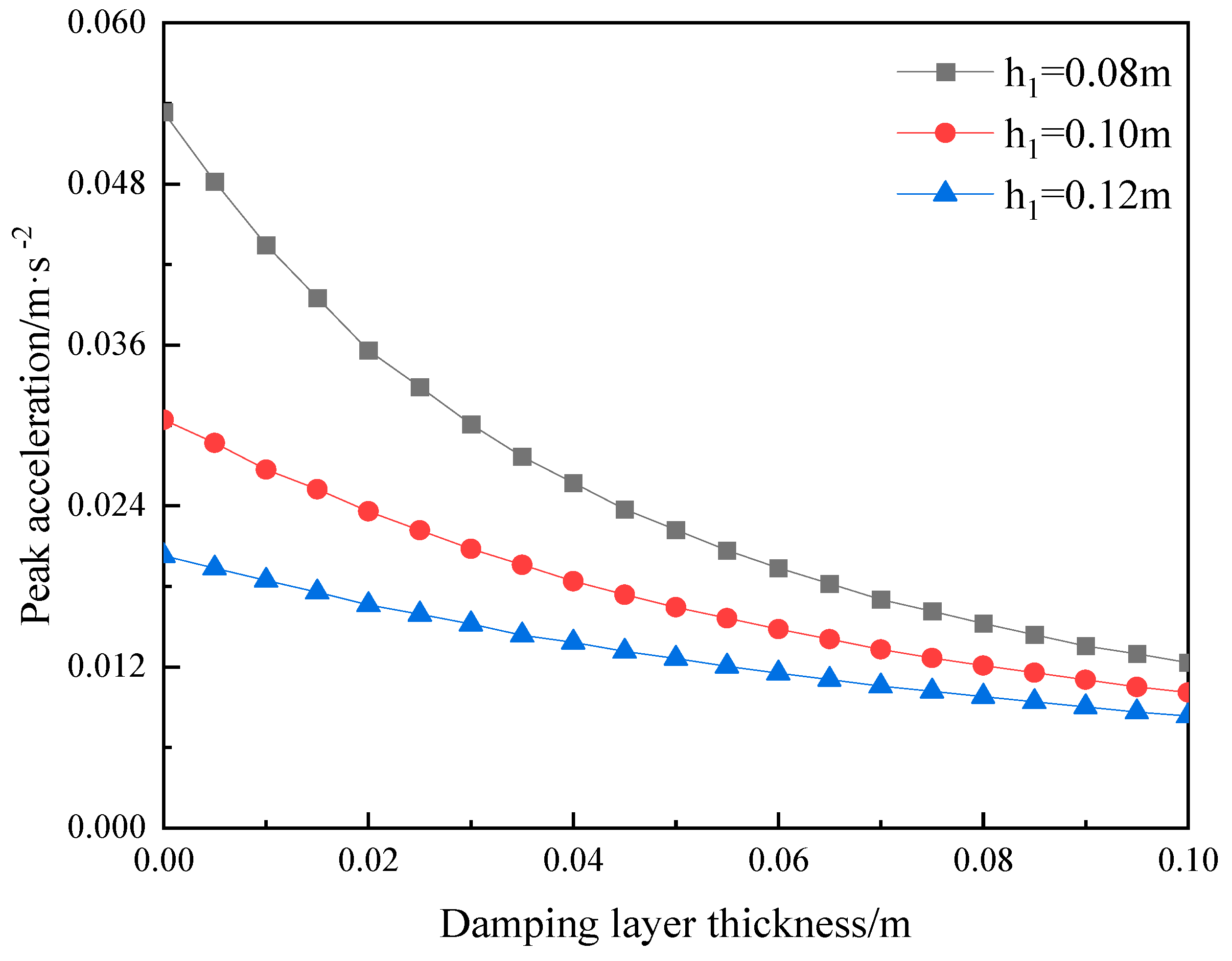
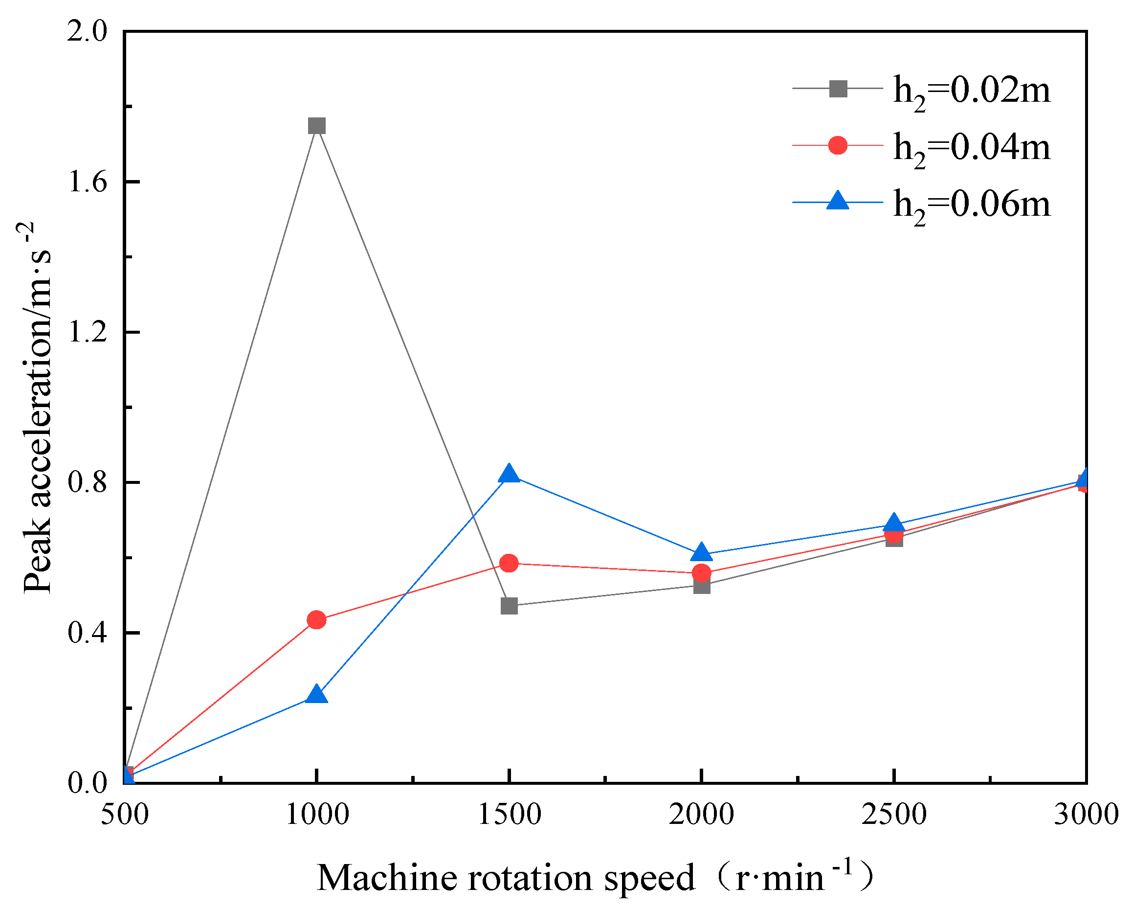
3.1. The Influence of Damping Layer Thickness

The analysis range for the thickness of the damping layer in engineering is 0 to 100 mm. Numerical calculations were performed to obtain the vertical acceleration peak of the damping composite floor slab with different structural layer thicknesses as a function of the damping layer thickness. The results are shown in Figure 7.
Figure 7 shows that the peak values of the acceleration responses of the vibration damping composite floor slabs under different thicknesses of the structural layer all gradually increase with the decrease of the thickness of the vibration damping layer. Moreover, when the thickness of the structural layer is 0.08 m, the change in the peak acceleration of the vibration damping composite floor slab with damping layer thickness is the most obvious. When the thickness of the vibration damped layer increases to 0.06 m, the decline rate of the peak acceleration decreases significantly. After the thickness of the vibration damping layer reaches 0.10 m, the slight difference in the thickness of the structural layer can be ignored, and when the thickness of the damping layer is 0.12 m, there is no obvious effect on the acceleration peak of the vibration damping composite floor. In conclusion, the damping layer thickness should be carefully designed to minimize acceleration response while ensuring that the floor thickness is not excessive. The thickness of the vibration damping layer is preferably around 0.06 m.

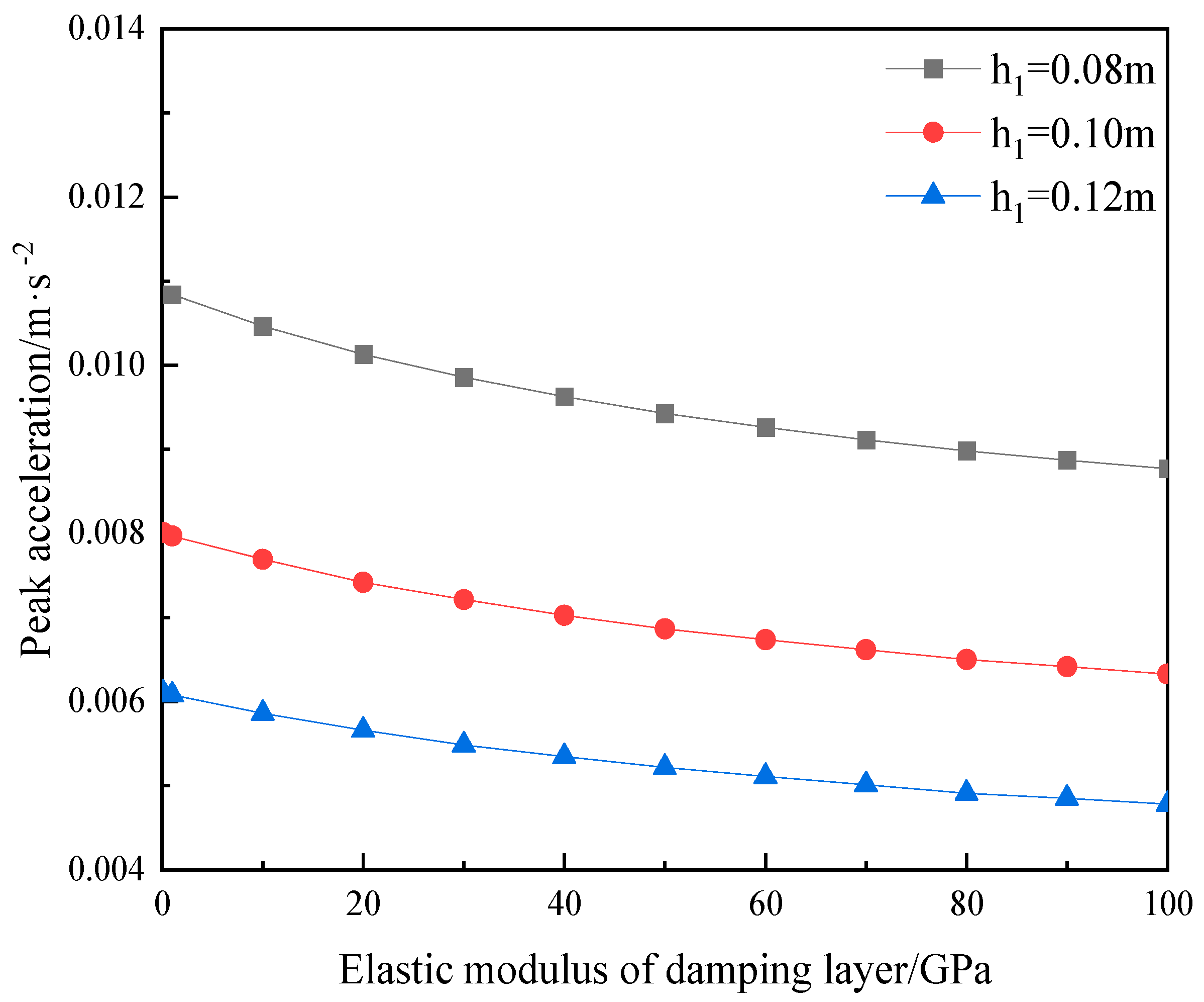
3.2. The Influence of Elastic Modulus of Damping Layer

Considering that the commonly used materials for the vibration damping layer of floor slabs in actual engineering projects are rubber-based vibration damping layers, polyurethane-based vibration damping layers, and spring isolators. Considering the material parameters of both flexible and rigid vibration damping layers, the analyzed range of the elastic modulus of the vibration damping layer is set to be 0.1 GPa to 100 GPa. Through numerical calculations, the curves of the peak vertical acceleration of the vibration damping composite floor slabs with different elastic modulus of the vibration damping layer have been obtained and are shown in Figure 8.
Figure 8 demonstrates that the variation in peak acceleration response among three distinct structural layer thicknesses maintains a relatively constant correlation with alterations in the elastic modulus. Additionally, these responses exhibit a gradual decline of approximately 20% as the elastic modulus of the damping layer increases. For example, when the structural layer thickness is 0.1 m, and the elastic modulus of the damping layer increases from 0.1 GPa to 100 GPa, the peak acceleration response of the vibration damping composite floor slab gradually decreases by 20.97%. Specifically, if the elastic modulus of the damping layer exceeds that of the structural layer (30 GPa), further increasing the elastic modulus of the damping layer will not significantly alleviate the acceleration response of the floor. However, when the elastic modulus of the damping layer is less than that of the structural layer (30 GPa), the greater the difference between the elastic modulus and the structural layer, the faster the peak acceleration increases. Therefore, when selecting a damping layer, it is crucial to manage and control any disparity in elastic moduli between it and that of the structural layer. For most common building floor slabs, a modulus of approximately 30 GPa for the vibration damped layer is most appropriate.

3.3. The Influence of the Load

In this section, the structural layer thickness of the composite floor slab is set to 0.10 m. The influence of loading modes on the peak acceleration response of the composite floor slab with different thicknesses of the vibration damping layer is analyzed.

3.3.1. The Influence of Fixed Harmonic Loads

The fixed harmonic loads are designed based on the centrifuge parameters provided in [25]. According to the Technical Standard for Vibration Comfort of Building Floor Structures (JGJ/T 441-2019) [24], both the amplitude and frequency of the vertical dynamic loads of the electric motor depend mainly on the rotational speed of the machine. In this section, the range of the machine’s rotational speed is from 500 r/min to 3000 r/min, and Table 9 presents the amplitudes and frequencies of the harmonic loads at different rotational speeds. Through numerical calculations, the curves of the peak vertical acceleration of the composite floor slab vary with the harmonic loads. The dynamic responses of the composite floor slab with different thicknesses of the vibration damping layer are shown in Figure 9.
As can be seen from Figure 8, the peak acceleration of the composite floor slab generally exhibits an increasing tendency with the increase of the machine’s rotational speed. When the machine rotational speed is 1000 r/min, the peak acceleration of the floor slab with the vibration damping layer thickness of 0.02 m reaches around 1.73 m/s 2, which is higher than other conditions. At this time, the load frequency corresponding to this machine’s rotational speed is 105 rad/s, which is close to the fundamental frequency (109.01 rad/s) of the floor slab with the vibration damping layer thickness of 0.02 m. The resonance reaction of the floor slab structure is induced by the frequency of the fixed harmonic load at this point. As the sampling interval of the machine rotation speed was set at 500 r/min, the harmonic load was not sampled near the fundamental frequency of the corresponding floor slab. Consequently, the resonant responses of the structure under the other two thicknesses of the vibration reduction layer could not be manifested. Additionally, by observing Figure 8, it can be noted that, when the machine rotational speed is higher than 1500 r/min, the three-floor slabs show similar peak acceleration. Therefore, when planning loads, the load frequency should preferably not be close to the fundamental frequency of the floor slab. In practical engineering, when the structural layer of the floor slab cannot be modified, the thickness of the vibration damping layer can be rationally designed to change the fundamental frequency of the floor slab, thereby avoiding resonance and improving the safety and comfort of the structure.

3.3.2. The Influence of Moving Loads

Amplitude of Moving Load

The amplitude of the moving load, ranging from 500 N to 5000 N, is designed based on [30]. Through numerical calculations, it can be observed from Figure 10 that the peak vertical acceleration of the composite floor slab increased with load amplitude.
Generally speaking, the peak acceleration response of the composite floor slab within the building exhibits a linear upward trend as the amplitude of the moving load increases. Furthermore, the slope of the curves decreases with the vibration damping layer thickness. This means that a floor slab with a thinner vibration damping layer is more sensitive to the moving load amplitude. When the thickness of the damping layer is maintained at 0.02 m and the load amplitude varies from 500 N to 5000 N, the peak acceleration of the floor slab escalates from 0.0177 m·s −2 to 0.0355 m·s −2.

Speed of Moving Load

Based on the parameters of the transport vehicles in the factory building provided in [3], the moving load speed is set to be 0.5 m·s −1 to 5 m·s −1. Through numerical calculation, results are shown in Figure 11, and it can be observed that the peak vertical acceleration of the composite floor slab increases with the moving load speed.
It can be seen from Figure 11 that the peak values of the vertical acceleration responses of the building’s composite floor slabs under different thicknesses of vibration reduction layer show a linear growth trend with the increase in the speed of the moving load. The variation trend of the peak acceleration in this section is consistent with that in the previous section. Meanwhile, it can also be demonstrated that, when the growth of the moving speed of the load reaches a certain value, the peak acceleration will also exhibit a tendency of peaks and troughs. Moreover, the increase in the thickness of the vibration reduction layer does not slow down the trend of the peak acceleration increasing with the increase in the speed of the moving load. Under the action of the moving load at the same speed, the greater the thickness of the vibration reduction layer, the smaller the peak acceleration.

3.3.3. The Influence of Load Position

Figure 12 illustrates the arrangement of load positions designed in this research. P1 denotes the location where the fixed harmonic load is applied, and the moving load is determined based on four paths. The numerical calculation results presented in Figure 13 demonstrate the variation of the vertical acceleration at the center of the vibration damped composite floor with respect to the load position.
Figure 13 illustrates that the displacement response trend of the center point of the plate remains consistent when moving loads on the same side. However, the amplitude varies due to the different distances between the path and the harmonic load at the center point of the plate. For the moving loads traveling along different edges, we know from Section 3.3.2 that, due to the inconsistent path lengths, the corresponding frequencies of the harmonic loads are also different. Even when the loads on the two paths move to the positions where the distances from the center point of the floor slab are the same, the vertical displacement responses of the vibration damping composite floor slab will still be different because of the disparity in the corresponding load frequencies. Therefore, when planning the travel routes of moving loads such as transport vehicles, in order to control the displacement response of the floor slab and reduce its vibration, the paths of moving loads are preferably designed along the long side of the slab. At the same time, the designed paths should not be too close to the positions where fixed loads act, so as to avoid excessive dynamic response in certain parts of the floor slab.

4. Conclusions

Based on the three-dimensional lamination theory, this paper establishes a computational model for vibration damping composite floor slabs. Taking into account the influence of the interlayer interactions, such as those of the decorative layer and the vibration damping layer, the displacement function is constructed by using the first kind of Chebyshev polynomials and trigonometric functions to theoretically solve the free vibration characteristics of vibration damped composite floor slabs and the dynamic response of the vibration damping composite floor slabs. By comparing with actual calculation examples, the accuracy of the method in this paper is verified. Moreover, the influence laws of different parameters on the vertical vibration of building composite floor slabs are explored, and the following conclusions are obtained:
  • Based on the theory proposed in this paper, the free vibration characteristics of the vibration damped composite floor slabs with simply supported edges on all four sides are calculated. When compared with the results in [26], the error of the dimensionless frequency is no more than 0.104%. When compared with the finite element results, the maximum error of the dimensionless frequency is no more than 0.720%. Evidently, the accuracy of the method presented in this paper is verified. Meanwhile, the matrix dimension required for the spectral method in this paper to reach the convergent value is only one-fourth of that in [26], which demonstrates the high efficiency of the calculation method proposed in this paper.
  • Based on the theory presented in this paper, the dynamic response of the vibration damped composite floor slabs with four-side simply supported boundaries is calculated. Under the action of fixed loads, the results of displacement responses and acceleration responses at the center point of the composite floor slab calculated by the method proposed in this paper are basically in line with those obtained from the single-plate theoretical solution. Under the action of moving loads or multi-source excitations, the displacement and acceleration responses calculated by the method in this paper are consistently greater than those calculated by the single-plate theoretical solution.
  • Based on the theory in this paper, a parametric analysis is carried out for the vibration damping composite floor slabs with four-side simply supported conditions. The impact of the thickness of the vibration reduction layer on the vertical vibration of the vibration reduction type composite floor slab is quite evident. However, after the thickness of the vibration reduction layer reaches 0.06 m, the curve of the peak acceleration of the composite floor slab declines rather gently. The peak value of the acceleration response of the floor slab exhibits exponential growth as the elastic modulus of the vibration reduction layer decreases. However, when the elastic modulus of the vibration reduction layer is greater than that of the structural layer (30 GPa), the increase in the elastic modulus has no significant impact on the peak acceleration of the building composite floor slab. The peak accelerations of the composite floor slabs with different thicknesses of the vibration reduction layer all increase linearly with the growth of the load amplitude. When the moving load moves along the short side of the floor slab, the displacement response of the floor slab is greater than that when the floor slab moves along its long side. Moreover, when the fixed load and the moving load act together, the closer the moving path of the moving load is to the fixed load, the greater the dynamic response of the floor slab near the position of the fixed load.

Author Contributions

Conceptualization, L.S.; methodology and software, T.X., F.T. and Y.Z.; resources, L.S.; writing—original draft preparation, T.X., F.T. and Y.Z.; writing—review and editing, L.S., H.Z. and A.H.M.; visualization, L.S. and A.H.M.; supervision, L.S., H.Z. and A.H.M.; project administration, L.S.; funding acquisition, L.S. All authors have read and agreed to the published version of the manuscript.

Funding

The reported research work is supported by the Wuhan Municipal Urban–Rural Development Bureau (202205, 202304).

Data Availability Statement

Data will be made available on request.

Conflicts of Interest

Author Feng Tian was employed by China Construction Third Engineering Group Co., Ltd. Author Yijie Zhang was employed by Power China Hubei Electric Engineering Co., Ltd. The remaining authors declare that the research was conducted in the absence of any commercial or financial relationships that could be construed as a potential conflict of interest.

Appendix A

K k u u = V ( C ¯ k 11 U 2 , x T U 2 , x + C ¯ k 16 U 2 , x T U 2 , y + C ¯ k 16 U 2 , y T U 2 , x + C ¯ k 66 U 2 , y T U 2 , y + C ¯ k 55 U 2 , z T U 2 , z ) d V , K k u v = V ( C ¯ k 12 U 2 , x T V 2 , y + C ¯ k 16 U 2 , x T V 2 , x + C ¯ k 26 U 2 , y T V 2 , y + C ¯ k 66 U 2 , y T V 2 , x + C ¯ k 45 U 2 , z T V 2 , z ) d V , K k u w = V ( C ¯ k 13 U 2 , x T W 2 , z + C ¯ k 36 U 2 , y T W 2 , z + C ¯ k 45 U 2 , z T W 2 , y + C ¯ k 55 U 2 , z T W 2 , x ) d V , K k v u = V ( C ¯ k 12 V 2 , y T U 2 , x T + C ¯ k 16 V 2 , x T U 2 , x T + C ¯ k 26 V 2 , y T U 2 , y + C ¯ k 66 V 2 , x T U 2 , y + C ¯ k 45 V 2 , z T U 2 , z ) d V , K k v v = V ( C ¯ k 66 V 2 , x T V 2 , x + C ¯ k 22 V 2 , y T V 2 , y + C ¯ k 44 V 2 , z T V 2 , z + C ¯ k 26 V 2 , x T V 2 , y + C ¯ k 26 V 2 , y T V 2 , x ) d V , K k v w = V ( C ¯ k 23 V 2 , y T W 2 , z + C ¯ k 36 V 2 , x T W 2 , z + C ¯ k 44 V 2 , z T W 2 , y + C ¯ k 45 V 2 , z T W 2 , x ) d V , K k w u = V ( C ¯ k 13 W 2 , z T U 2 , x + C ¯ k 36 W 2 , z T U 2 , y + C ¯ k 45 W 2 , y T U 2 , z + C ¯ k 55 W 2 , x T U 2 , z ) d V , K k w v = V ( C ¯ k 23 W 2 , z T V 2 , y + C ¯ k 36 W 2 , z T V 2 , x + C ¯ k 44 W 2 , y T V 2 , z + C ¯ k 45 W 2 , x T V 2 , z ) d V , K k w w = V ( C ¯ k 33 W 2 , z T W 2 , z + C ¯ k 44 W 2 , y T W 2 , y + C ¯ k 55 W 2 , x T W 2 , x + C ¯ k 45 W 2 , x T W 2 , y + C ¯ k 45 W 2 , y T W 2 , x ) d V , M k u u = V ( ρ U T U ) d V , M k v v = V ( ρ V T V ) d V , M k w w = V ( ρ W T W ) d V .
where Kkuu represents the force on the u-node caused by applying a unit displacement to the u-node on the k-th layer, and the same applies to other similar cases; C ¯ k 11 represents the coefficient of the stress–strain relationship matrix on the k-th layer, and so on; U2,x represents the second-order partial derivative of the strain energy with respect to the x-coordinate, and so on; Mkuu represents the mass distribution of the structure on the k-th layer in the direction of the horizontal displacement degree of freedom, and so on; and ρ represents the structural density.

References

  1. Xu, Z.; Lou, Y.; Chen, L. Vibration Measurement and Prediction for Foundation Slab Design of a High-tech Lab Based on in Situ Testing. Shock Vib. 2020, 2020, 8892597. [Google Scholar] [CrossRef]
  2. Kawrza, M.; Furtmüller, T.; Adam, C. Experimental and Numerical Modal Analysis of a Cross Laminated Timber Floor System in Different Construction States. Constr. Build. Mater. 2022, 344, 128032. [Google Scholar] [CrossRef]
  3. He, H.L.; Zhou, N.L.; Yuan, W.D. Evolutionary Topology Optimization of Damped Plates Based on Multiple Modes’ Damping Ratio. Chin. J. Eng. Des. 2015, 4, 351–358+364. [Google Scholar]
  4. Stochino, F.; Alibeigibeni, A.; Zucca, M.; Valdes, M.; Concu, G.; Simoncelli, M.; Pisani, M.A.; Bernuzzi, C. Mechanical behavior of composite slabs with recycled concrete aggregates: A preliminary study. Structures 2024, 70, 107838. [Google Scholar] [CrossRef]
  5. Zhai, Y.C.; Ma, J.; Sun, J.M.; Liang, S. Influence of Damping Thickness Layer Thickness on Free Vibration of Composites Sandwich Plate. Mach. Des. Manuf. 2017, 7, 78–81. [Google Scholar]
  6. Hu, S.W.; Zhong, R.; Qin, B.; Wang, Q.S. Vibration Characteristics of Arbitrary Straight Quadrilateral Composite Laminates. J. Harbin Eng. Univ. 2022, 43, 385–391. [Google Scholar]
  7. Yuan, W.H.; Li, F.L.; Lv, M. Free Vibration Characteristics of Corrugated Sandwich Plates Under Different Boundary Conditions. Acta Mater. Compos. Sin. 2020, 37, 3149–3159. [Google Scholar]
  8. Devin, A.; Fanning, P.; Pavic, A. Modelling Effect of Non-structural Partitions on Floor Modal Properties. Eng. Struct. 2015, 91, 58–69. [Google Scholar] [CrossRef]
  9. Cao, D.; Pan, Z.; Fang, Y. Dynamic Response Analysis of the Floor Structure Under Random Crowd Excitation. Shock Vib. 2024, 2024, 1451839. [Google Scholar] [CrossRef]
  10. Chen, S.M.; Zhang, R.; Zhang, J. Human-induced Vibration of Steel-concrete Composite Floors. Proc. Inst. Civ. Eng.-Struct. Build. 2018, 171, 50–63. [Google Scholar] [CrossRef]
  11. Lee, C.; Wang, Y.; Su, R.K.L.; Chen, Y.T. Fragility Analysis of Floor Micro Vibrations Induced by Internal Vehicles in High Technology Factories. Structures 2022, 40, 679–692. [Google Scholar] [CrossRef]
  12. Lu, H.; Zhou, L.; Fang, C.; Wu, B.T.; Gao, Z.C. An Effective Equivalent Vibration Analysis Method of the Profiled Steel Sheet-concrete Composite Floor Caused by High-speed Train. J. Vib. Eng. Technol. 2023, 11, 2361–2372. [Google Scholar] [CrossRef]
  13. Lu, H.X.; Zhou, L.; Liu, M.H.; Wu, B.T. Analysis of Vibration Characteristics of Different Forms of Floor Slab of Steel Frame Structures Under Train Excitation. Noise Vib. Control 2023, 43, 221–227. [Google Scholar]
  14. Ju, S.H.; Kuo, H.H.; Yu, S.W.; Ni, S.H. Investigation of Vibration Induced By Moving Cranes in High-tech Factories. J. Low Freq. Noise Vib. Act. Control 2019, 39, 84–97. [Google Scholar] [CrossRef]
  15. Li, S.J.; Zhang, T.; Wang, J.F. Analysis of Vibration Serviceability of Composite Floor with Steel Truss under Walking Load. J. Hefei Univ. Technol. (Nat. Sci.) 2021, 44, 801–805. [Google Scholar]
  16. Sun, L.M.; Liu, S.G.; Zhao, H.B.; Muhammad, U.; Chen, D.; Li, W.G. Dynamic Performance of Fiber-reinforced Ultra-high Toughness Cementitious Composites: A Comprehensive Review from Materials to Structural Applications. Eng. Struct. 2024, 317, 118647. [Google Scholar] [CrossRef]
  17. Sun, L.M.; Liu, S.G.; Kong, F.; Zhao, H.B. Analytical Solution for Dynamic Response of a Reinforced Concrete Beam with Viscoelastic Bearings Subjected to Moving Loads. Materials 2024, 17, 4491. [Google Scholar] [CrossRef]
  18. Kim, J.H.; Jeon, J.Y. Effects of Upper Surface Layers on the Vibration Characteristics of Floating Floor Systems in Concrete Slab Structures. J. Acoust. Soc. Am. 2012, 131, 3320. [Google Scholar] [CrossRef]
  19. Zhang, X.; Wang, Q.M.; Wang, Y.S.; Li, Q. Experimental and Analytical Study on the Vibration Performance of U-Shaped Steel-Concrete Composite Hollow Waffle Slab. Shock. Vib. 2020, 2020, 1928075. [Google Scholar] [CrossRef]
  20. Afzali, S.A.; Özer, C.; Bayrak, B.; Bayrak, B.; Sadid, A.J.; Celebi, O. the Bending Behavior and Free Vibration of the Concrete-Steel Composite Floors. Adv. Steel Constr. 2023, 19, 209–222. [Google Scholar]
  21. Guo, J.Y.; Lin, Q.L.; Di, G.Q. The Transmission Characteristics and Influence Prediction of Impulsive Vibration Caused by a Solid Metal Ball Impact in Buildings. J. Low Freq. Noise Vib. Act. Control 2023, 42, 839–850. [Google Scholar] [CrossRef]
  22. Tahmasebinia, F.; Yip, C.S.; Lok, C.F.; Lok, C.F.; Sun, Y.F.; Wu, J.Y. Dynamic Behavior of the Composite Steel-Concrete Beam Floor Systems under Free and Forced Vibration. Buildings 2022, 12, 320. [Google Scholar] [CrossRef]
  23. Lu, H.X.; Liu, M.H.; Fang, C.; Wu, B.T.; Liang, P.Y. Study on Equivalent Calculation Model of Profiled Steel Sheet and Concrete Composite Floors Based on Vibration Analysis. Noise Vib. Control 2022, 42, 212–218. [Google Scholar]
  24. Zhou, D.; Cheung, Y.K.; Au, F.T.K.; Lo, S.H. Three-dimensional Vibration Analysis of Thick Rectangular Plates Using Chebyshev Polynomial and Ritz Method. Int. J. Solids Struct. 2002, 39, 6339–6353. [Google Scholar] [CrossRef]
  25. Qu, Y.; Wu, S.; Li, H.; Meng, G. Three-dimensional Free and Transient Vibration Analysis of Composite Laminated and Sandwich Rectangular Parallelepipeds: Beams, Plates and Solids. Compos. Part B Eng. 2015, 73, 96–110. [Google Scholar] [CrossRef]
  26. Ye, T.G.; Jin, G.Y.; Liu, Z.G. Effects of transverse shear and normal deformations on the vibration characteristics of laminated plates. J. Vib. Shock 2019, 38, 118–125. [Google Scholar]
  27. JGJ/T 441-2019; Technical Standard for Vibration Comfort of Building Floor Structures. Architecture & Building Press: Beijing, China, 2020.
  28. He, S.G.; Tang, H.; Shi, K.R.; Jiang, Z.R.; Chen, R.Y. Evaluation of Human Comfort for Floor Vibration Induced by Equipment in High-rise Industrial Building. Spec. Struct. 2023, 40, 6–13. [Google Scholar]
  29. Cao, Z.Y. Vibration Theory of Plates and Shells; Railway Publishing House: Beijing, China, 1989. [Google Scholar]
  30. Lee, C.; Wang, Y. Assessment of Floor Micro-vibrations Induced by Moving Vehicles in High Technology Factories Using a Fragility-based Method. IOP Conf. Ser. Earth Environ. Sci. 2019, 283, 012067. [Google Scholar] [CrossRef]
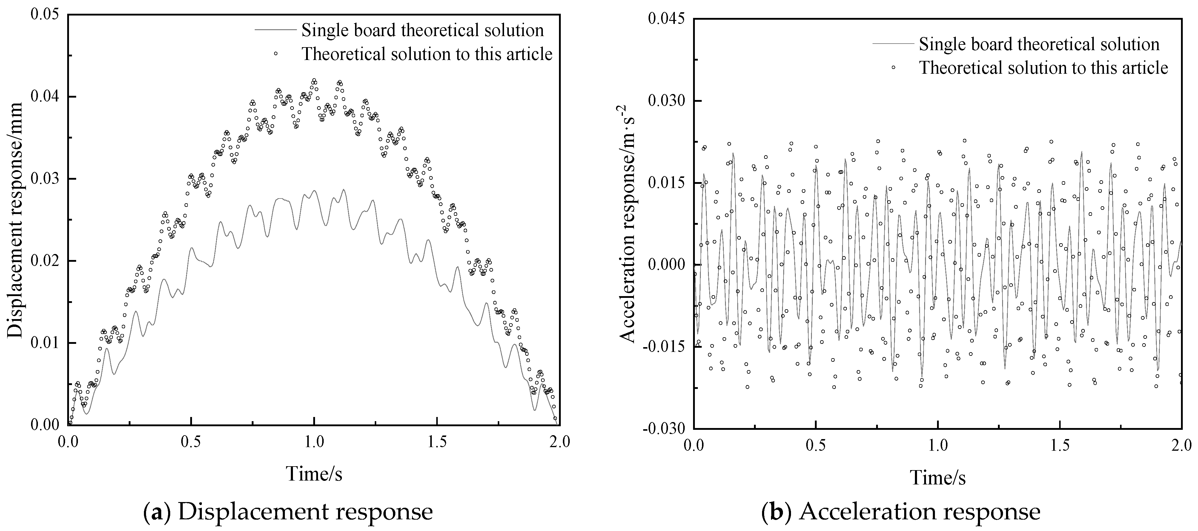
Figure 1. Analysis model and coordinate system of vibration damped composite floor slab.
Jcs 09 00057 g001
Figure 2. Modal vibration modes of the composite floor slab with four-sides simply supported.
Jcs 09 00057 g002
Figure 3. Layout diagrams of fixed loads and moving loads.
Jcs 09 00057 g003
Figure 4. Comparison of the vertical vibration responses at the center point of the floor slab under harmonic loads. (a) displacement, (b) acceleration.
Jcs 09 00057 g004
Figure 5. Comparison of the vertical vibration responses at the center point of the floor slab under moving loads.
Jcs 09 00057 g005
Figure 6. Comparison of vertical vibration response at the center point of a vibration damped composite floor slab under multi-source excitation.
Jcs 09 00057 g006
Figure 7. Effect of damping layer thickness on dynamic response of composite floor slabs.
Jcs 09 00057 g007
Figure 8. Effect of elastic modulus of damping layer on the dynamic response of composite floor slabs.
Jcs 09 00057 g008
Figure 9. The influence of harmonic loads on the dynamic response of composite floor slabs.
Jcs 09 00057 g009
Figure 10. The influence of the amplitude of moving loads on the dynamic response of composite floor slabs in buildings.
Jcs 09 00057 g010
Figure 11. The influence of the load velocity on the peak acceleration responses of composite floor slabs.
Jcs 09 00057 g011
Figure 12. Layout diagram of various loads.
Jcs 09 00057 g012
Figure 13. Floor displacement response under different load positions.
Jcs 09 00057 g013
Table 5. Comparison of peak vibration responses at the center point of the floor slab under moving loads.
Working ConditionPeak Displacement Response
(10 −3·mm)
Peak Acceleration
Response (mm·s−2)
Peak Displacement ErrorPeak Acceleration
Error
Theoretical solution proposed in this research40.007.5247.06%23.29%
Single board theoretical solution27.206.10
Table 6. Calculation parameters of floor slabs under multi-source excitation.
ParametersValueParametersValue
Moving load amplitude/N2000Fixed harmonic load amplitude/N39.69
Moving load speed/m·s−12Fixed harmonic load frequency/rad·s−152.5
Table 7. Comparison of peak vibration responses at the center point of the floor slab under multi-source excitation.
Working ConditionPeak Displacement
Response (10−3·mm)
Peak Acceleration
Response (mm·s−2)
Peak Displacement ErrorPeak Acceleration
Error
Theoretical solution proposed in this research42.0022.7146.34%9.55%
Single board theoretical solution28.7020.73
Table 8. Calculation parameters of floor slabs in parameter analysis.
Structural Layer ParametersValueDamping Layer
Parameters
ValueDecorative Layer ParametersValue
Elastic modulus30 GPaElastic modulus0.3 GPaElastic modulus27 GPa
Density2500 kg·m−3Density1000 kg·m−3Density2500 kg·m−3
Poisson’s ratio0.3Poisson’s ratio0.2Poisson’s ratio0.2
Thickness0.10 mThickness0.02 mThickness0.02 m
Table 9. Load parameters under different rotational speeds.
Machine Rotational Speed (r/min)50010001500200025003000
Load frequency (rad/s)52.5105157.5210262.5315
Load amplitude (N)39.69158.76357.21635.04992.251428.84
Disclaimer/Publisher’s Note: The statements, opinions and data contained in all publications are solely those of the individual author(s) and contributor(s) and not of MDPI and/or the editor(s). MDPI and/or the editor(s) disclaim responsibility for any injury to people or property resulting from any ideas, methods, instructions or products referred to in the content.

