Article

Observations from Processing Thick Continuous Fiber Polyphenylene Sulfide (PPS) Laminates with and Without Carbon Black

1
Advanced Structures and Composites Center, University of Maine, Orono, ME 04469, USA
2
U.S. Army DEVCOM Ground Vehicle Systems Center, Warren, MI 48397, USA
*
Author to whom correspondence should be addressed.
J. Compos. Sci. 2025, 9(12), 669; https://doi.org/10.3390/jcs9120669
Submission received: 28 July 2025 / Revised: 18 November 2025 / Accepted: 26 November 2025 / Published: 3 December 2025
(This article belongs to the Special Issue Advances in Continuous Fiber Reinforced Thermoplastic Composites)

Abstract

During the manufacturing and development of a proof-of-concept prototype of a continuous fiber polyphenylene sulfide (PPS) composite vehicle component, unexpected results were observed in thick laminates of an E-glass-fiber-reinforced PPS matrix, which utilized carbon black as a colorant (GF/PPS+CB). Extensive interlaminar macrocracking, transverse intralaminar microcracking, and micro-/macrovoids were observed in GF/PPS+CB laminates after compression forming. When processed under identical conditions, no micro-/macrocracking or voids were present in GF/PPS laminates and carbon fiber/PPS laminates without carbon black colorant. These observations prompted further investigation into the influence of processing conditions, presence of colorant, mold design (open and closed molds), and geometry (flat and curved) on the development of matrix defects in thick continuous fiber-reinforced PPS laminates.

1. Introduction

A proof-of-concept composite vehicle component was engineered and fabricated using continuous fiber-reinforced thermoplastic materials with the objective of demonstrating maximum vehicle lightweighting compared to the baseline aluminum component. The composite component was designed to be subjected to extreme dynamic structural loads and varying environmental thermal loads, ranging from arctic to desert climates, to be resistant to flammability and smoke generation, and have low smoke toxicity (FST). Several thermoplastic polymers were considered for the component’s laminate matrix including polyphenylene sulfide (PPS), polyethylene terephthalate (PET), polyethylene terephthalate glycol (PETG), polycarbonate (PC), and polypropylene (PP).
PPS is an engineering thermoplastic with an excellent combination of thermal and mechanical properties, chemical and impact resistance, low water absorption, and inherent flame resistance [1,2,3]. PPS composites are utilized in a wide variety of industries, including automotives [4,5], aviation, electronics, and precision machinery. Carbon- and glass-fiber reinforced PPS composites have replaced lightweight aluminum structures in aircraft such as the Airbus A340-500, A340-600, A350 XWB, and A400M [6,7,8,9]. PPS polymer was selected as the vehicle component’s laminate matrix due to it being the only polymer candidate that passed all FST requirements, and due to it having glass transition temperature (Tg) and heat deflection temperature (HDT) properties that met the vehicle’s thermal environment requirements.
To achieve the desired balance of structural performance and cost, both carbon-fiber- and E-glass-fiber-reinforced PPS tapes (CF/PPS and GF/PPS, respectively) were utilized to fabricate the vehicle component preform using automated tape layup (ATL). Selecting tapes of both fiber types with the same manufacturer’s matrix polymer was important because these tapes would be co-processed to produce the vehicle component. Several tape manufacturers were considered, but, at the time, only one manufacturer offered both CF/PPS and GF/PPS tapes which were suitable for use in ATL. Consequently, their materials were selected for application to the composite vehicle component. To handle the applied structural loading, an approximately 16 mm (5/8 in) thick quasi-isotropic laminate was designed with 80% GF/PPS and 20% CF/PPS plies (by weight), which saved 58% weight over the baseline aluminum component. The carbon plies were split evenly between the top and bottom of the laminate, sandwiching the GF/PPS plies.
This program was executed during the period of late 2019 through 2023—a timeframe when the industry was experiencing especially severe supply chain disruptions—so laminate processing options were limited by mold designs that could be fabricated and delivered within the program’s timeline and budget and by limitations of in-house processing equipment. After tape layup, the laminate preform was heated and compression-formed using an open-sided matched-metal mold in a heated thermoforming press that was designed for rapid stamp forming. The preform was heated to a target temperature in the middle of PPS’s Differential Scanning Calorimetry (DSC)-derived typical melt temperature (Tm) range, ensuring that the temperature was high enough to enable sufficient matrix flow for forming, and ply-to-ply miscibility and adhesion, but not too high to prevent excessive matrix flow-inducing preform fiber wash (fiber wash is displacement/distortion of fiber geometry due to shearing caused by in-plane polymer flow). According to Spruiell and Janke [2], PPS’s DSC-derived Tm typically ranges from 280–295 °C (536–563 °F), depending on the size of the crystals and, therefore, on the conditions used to generate them (i.e., prior thermal history). Nohora et al. [3] state that PPS composites require a processing temperature of 340 °C (645 °F) to eliminate all crystals or highly ordered regions; otherwise, remnant crystals will act as nucleation sites during cooling from melt, which increases the crystallization rate. Processing at this higher temperature requires a closed-sided mold. Otherwise, the majority of the PPS matrix would flow out of the laminate and cause extreme fiber wash. Manufacturing a closed-sided component mold was preferred but not an option for the program, which meant the preform’s PPS matrix could not be heated high enough above its Tm to ensure all crystallinity was eliminated before cooling. While this limitation in the mold design was not ideal, the resulting study provides important insight into the downstream effects that can occur when manufacturing continuous fiber-reinforced thermoplastic composites in a constrained manufacturing environment. Later in this effort, a closed-sided mold was fabricated to study the differences in laminate defects observed in processing at Tm and at 340 °C (645 °F), enabled by the two different mold configurations.
Neither the large mass of the thermoforming press nor the matched-metal tooling used to fabricate the component had active cooling, resulting in the laminate experiencing a very slow cooling rate, averaging 0.3 °C/min (0.6 °F/min) between PPS’s Tm and Tg. The cool-down rate from melt affects the level of crystallinity and morphology in semicrystalline polymers, which, in turn, dictates the polymer’s mechanical and thermal properties [3]. Oshima et al. [10] report that increased crystallinity increases laminate composite properties dominated by matrix stiffness, while composite properties dominated by matrix ductility (e.g., fracture toughness and ultimate strength) decrease with increased crystallinity. Both a slow cool-down rate from melt and annealing a semicrystalline polymer at temperatures above its Tg will increase crystallinity compared to fast cooling rates [11,12]. Zhao et al. [1] reports a crystallization window of 87–270 °C (189–518 °F) between PPS’s Tg and Tm, respectively, for CF/PPS composites. Spruiell [2] reports that the maximum crystallization rate occurs at 180–190 °C (356–374 °F), midway between the Tg and Tm. Mechanical properties reported in [10] show approximately a 5% average increase in 90° tensile (matrix dominated) stiffness and a 12% lower average 90° tensile strength for CF/PPS cooled using 1 °C/min versus 10 °C/min cool rates. For the composite vehicle component, a balance between stiffness and strength was desired, so active cooling in the thermoforming press and/or mold—especially in the temperature range between Tm and Tg—was desired to control the laminate’s cooling rate and resulting properties, but this was not possible within the program’s limitations.
Carbon black is a nearly pure (typically >97%) elemental form of paracrystalline carbon with high surface area-to-volume ratio [13]. Carbon black particles are most easily characterized by their diameters, which, individually, typically range from 20 nanometers (nm) to 60 nm but exist mainly as aggregates that more accurately represent their size. PPS’s unit cell size is approximately 1 nm, and its crystalline or ordered regions can range up to a few hundred nanometers. Horrocks et al. [14] note that when carbon black’s fundamental particle size is the same order of magnitude as the ordered domains or crystalline regions of a polymer, strong interactions can be expected with its crystalline formation. Lin et al. [15] state that carbon black aggregates are known to act as nucleating sites for polymer crystallization and significantly increase crystallization rates during melt processing.
The definition of the maximum achievable crystallinity of PPS polymer varies widely within the literature depending on numerous factors, including the measurement method used (e.g., DSC, X-Ray Diffraction (XRD), Dynamic Mechanical Analysis (DMA), Fourier Transform Infrared Spectroscopy (FTIR)), maximum processing temperature, cooling rate, annealing, etc. Brady [16] reports a maximum crystallinity of approximately 65% measured via XRD for neat PPS after annealing at 204 °C (399 °F) for 240 min. Lee et al. [17] used DSC and DMA to measure the maximum crystallinity of 20% GF-reinforced PPS composites, achieving 27% via DSC and 78% via DMA after annealing at 204 °C (399 °F) for 120 min, exemplifying the large differences that can be produced with different measurement methods.
Semicrystalline polymers decrease in volume during cooling after melt processing. This is largely caused by crystalline formation ordering the packing of molecules, which reduces the free volume and produces a more compact molecular structure than the amorphous phase, thus resulting in polymer shrinkage. As the polymer’s crystallinity increases, the shrinkage also increases [18]. Research defining measured shrinkage of continuous fiber-reinforced PPS was scarce. Golzar et al. [19] reports the through-thickness shrinkage for thin 1.92 mm (0.076 in) CF/PPS laminates to be approximately 3.2%. These laminates were prepared by heating at 7.5 °C/min (13.5 °F/min) up to 330 °C (626 °F), held for 20 min, then cooled at 15 °C/min (27 °F/min).
This article provides a qualitative summary of results of processing continuous fiber-reinforced PPS tapes with and without carbon black additive. The original objective of this manufacturing research effort was to engineer, fabricate, and test the performance of a lightweight composite vehicle component using a co-processed CF/PPS and GF/PPS sandwich structure. However, observed defects in the manufactured part prompted further investigation of the effects of additives on the processing and quality of the part. The trials summarized herein to explore the results were a detour from the program’s intended scope. As such, limited results and images were collected.

2. Materials and Equipment

2.1. Materials

Materials obtained for this program included E-glass and standard modulus carbon continuous fiber PPS-reinforced tapes typically used in automated tape layup machines. At the start of the program, black-colored CFR-TP PPS GF60-01 glass fiber/PPS (GF/PPS) and CF60-01 natural-color carbon fiber/PPS (CF/PPS) tapes were purchased. The fiber content for both tapes was 60% by weight, as per their technical datasheets. GF60-01 is reported by the manufacturer as being available in a natural-color matrix or black-color matrix; this indicates no colorant/additive and carbon black additive, respectively. At the time of purchase, the authors were unaware that carbon black was used as a colorant for the black GF/PPS tape. After initial processing trials with black GF/PPS, which produced unexpected and unwanted results, small samples of natural-color matrix GF/PPS were provided by the manufacturer to perform limited trials for comparison to the black-colored GF/PPS. For clarity, the following nomenclature will be used to describe the different types of materials:
  • CF/PPS ≡ carbon-fiber-reinforced natural-color PPS matrix (without carbon black or other additives).
  • Note: CF/PPS was not offered commercially by the manufacturer with carbon black colorant.
  • GF/PPS+CB ≡ E-glass-fiber-reinforced PPS matrix with carbon black colorant, referred to earlier as black GF/PPS or black-colored GF/PPS.
  • Note: Carbon black type and loading concentration was not made available by the manufacturer.
  • GF/PPS-NA ≡ E-glass-fiber-reinforced natural-color PPS matrix (without carbon black or other additives).
  • Note: Two different natural color glass tapes were acquired: 60% and 70% fiber content by weight.

2.2. Tooling

An open-sided 655 kg steel matched-mold, ranging in thickness between 29 mm and 70 mm (1.15 in to 2.75 in) per side, was used for compression forming of the vehicle component.

2.3. Equipment

A FiberForge RELAY Station 2000 ATL machine (Dieffenbacher Group, Eppingen, Germany) was used to precisely fabricate all preforms.
Each of the mold’s top and bottom sections were mounted in a Techni Modul 700 ton hydraulic fast-reaction thermoforming press (Techni-Modul Engineering, Coudes, France) to provide mold-to-preform conductive heating and forming/consolidation pressure.
In support of the larger-scale work, small flat panel consolidation trials were performed in a CMG30H-15-CPX Monarch 30-ton press (Carver, Wabash, IN, USA).

3. Fabrication Trials and Results

3.1. Vehicle Component Consolidation

At the start of each vehicle component consolidation, the matched molds mounted in the thermoforming press contacted the preform with light pressure, approximately 69 kPa (10 psi), to enable conductive heating. The preform was heated from room temperature to the target part consolidation temperature of 288 °C (550 °F), as measured by thermocouples located in the laminate’s midplane approximately 25 mm (1 in) inward from the sides. Pressure was adjusted to maintain light mold contact with the preform as the plies’ stiffness dropped due to heating. After reaching target temperature, heating remained under light contact pressure for approximately ten (10) minutes, and then 690 kPa (100 psi) part pressure was applied. After full pressure was achieved, the press heat was turned off, and the mold was allowed to cool passively while pressure was maintained throughout cooling.
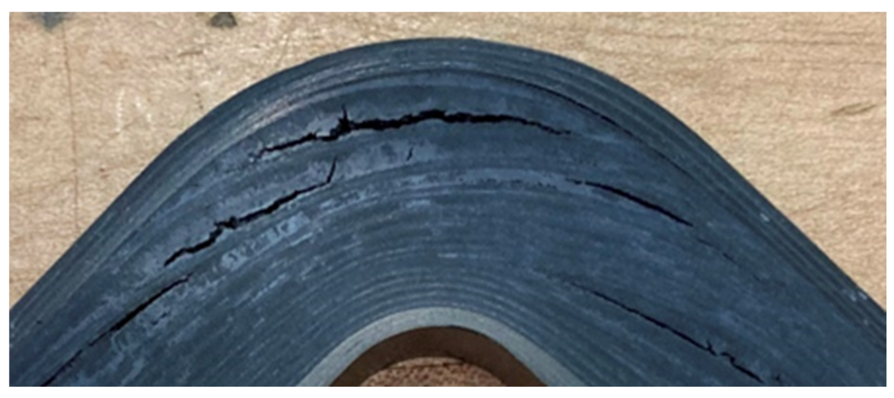
A cross-section of a consolidated hybrid-layup vehicle component (Figure 1), taken at one of the component’s curved regions, shows over-consolidation for plies toward the inner surface and under-consolidation (bridging) for the plies toward the outer surface. Over- and under-consolidation of plies and bridging were not unexpected results, as this was one of the first components fabricated and the processing had not been refined to enable sufficient fiber slip to achieve correct consolidation during compression forming. What was unexpected were the very large interlaminar cracks (macrocracks) in the matrix-rich regions, typical for all curved regions in this component. This was the first indication that the GF/PPS+CB was not processing as expected. No sign of insufficient consolidation or delamination in the outer CF/PPS plies was visible before or after waterjet cutting.
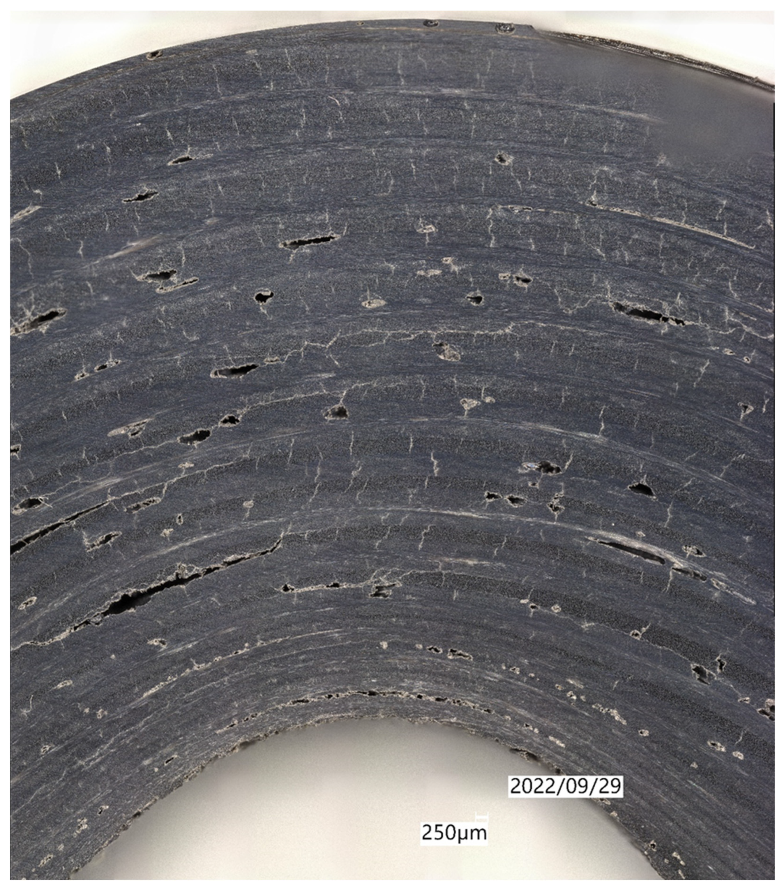
Component consolidation trials using only GF/PPS+CB plies were performed to understand the influence of ply bridging in the curved regions that caused the interlaminar macrocracks seen in Figure 1. A sub-size, but full-thickness (16 mm [5/8 in]), layup was consolidated, reproducing only the curved region shown in Figure 1. Figure 2 shows a magnified section of the curved laminate region. Bridging was effectively eliminated (due to sufficient fiber slip), and the size of interlaminar macrocracks was reduced significantly. However, voids, intralaminar microcracks, and (smaller) interlaminar macrocracks persisted throughout the laminate, which was unexpected.

3.2. Flat Panel Matrix Quality Investigation

3.2.1. GF/PPS+CB and CF/PPS at 288 °C (550 °F) and 690 kPa (100 psi)

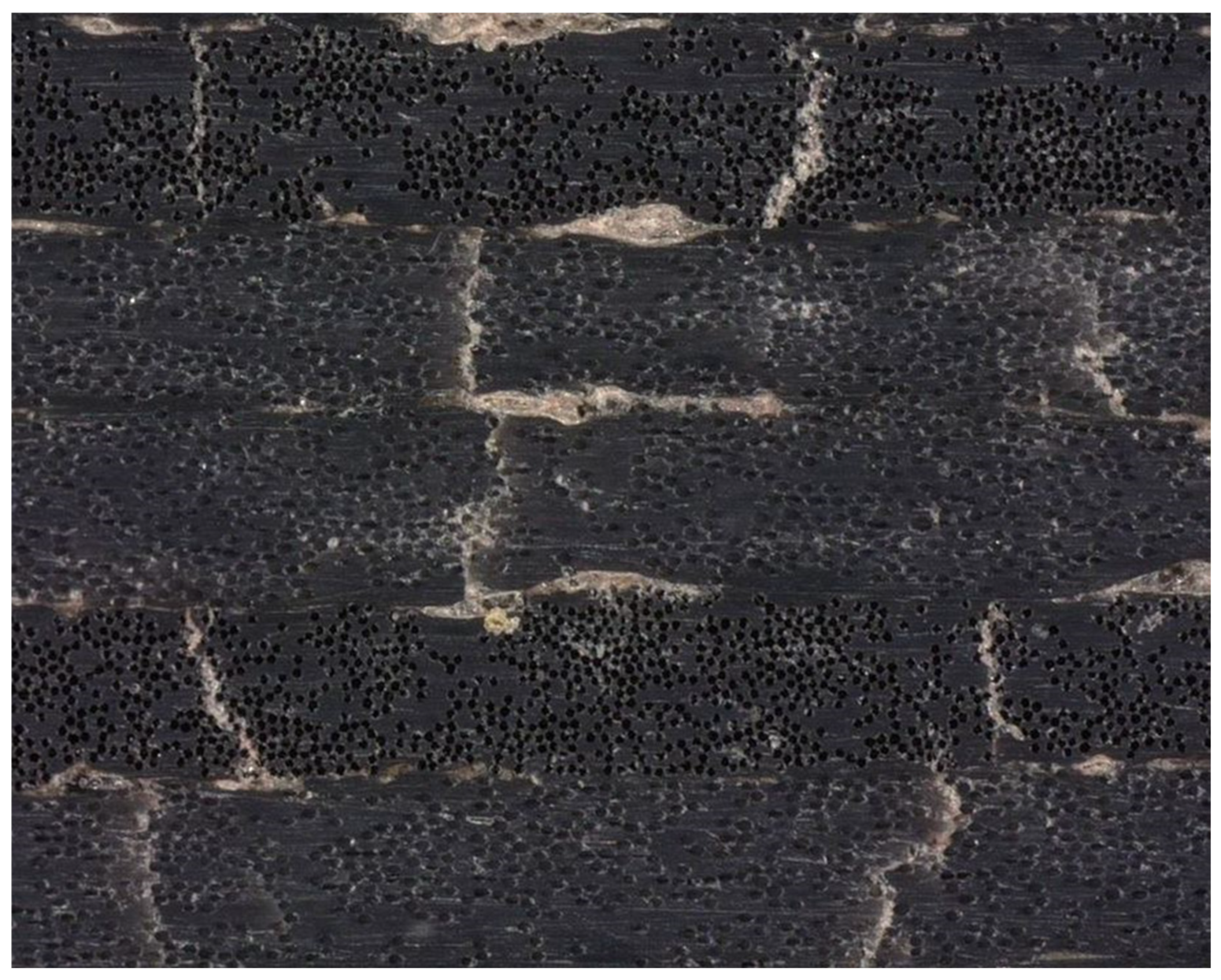
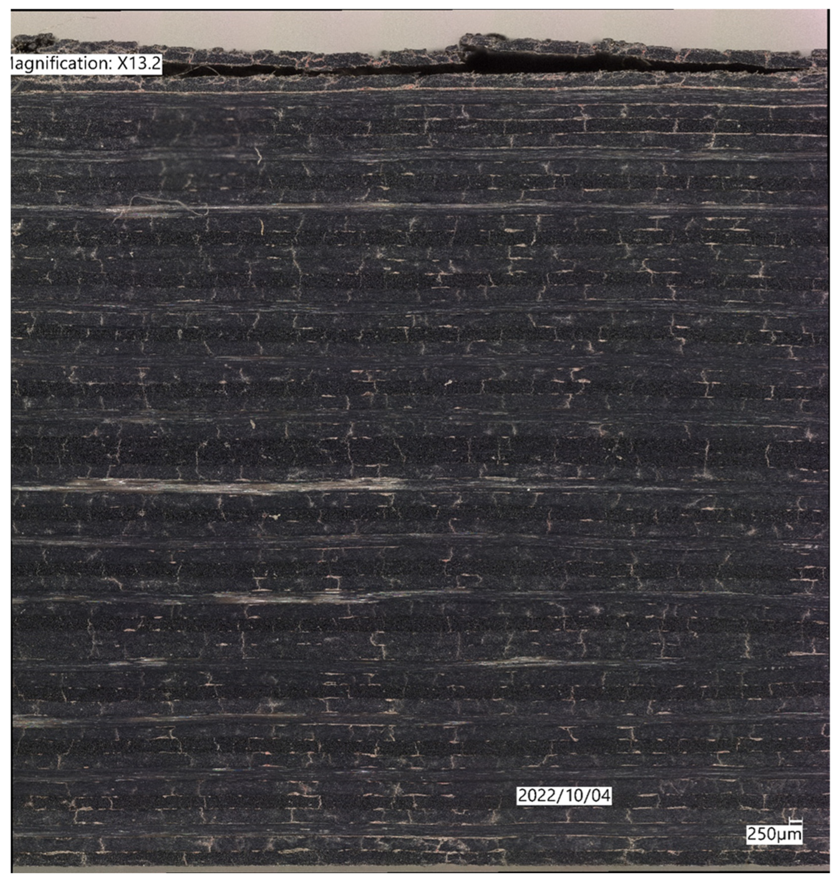
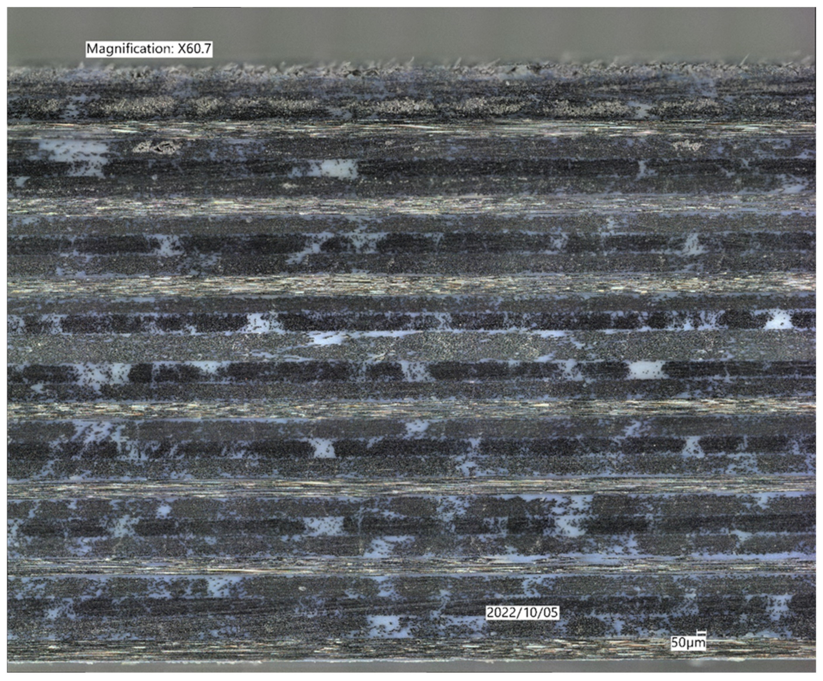
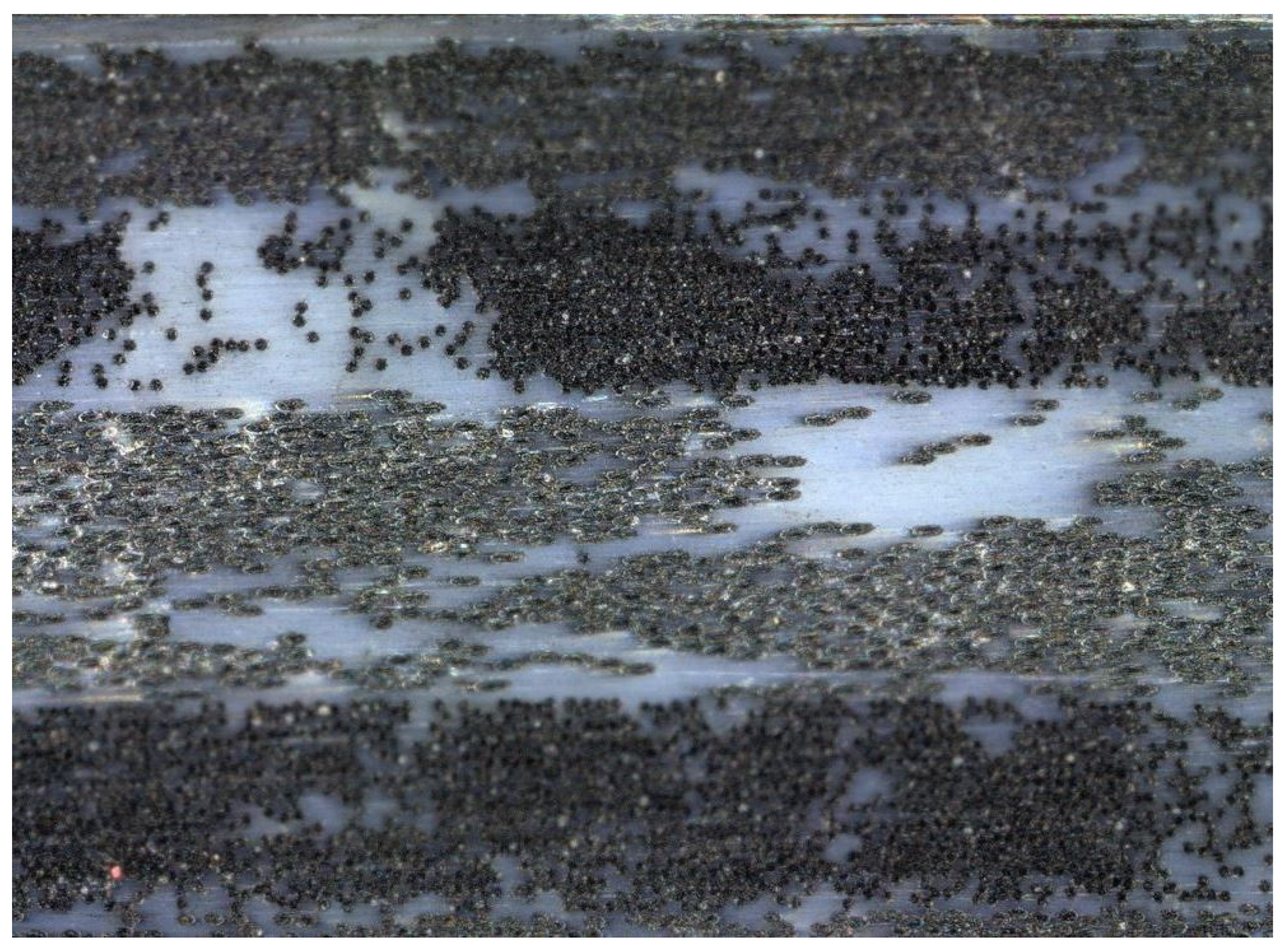
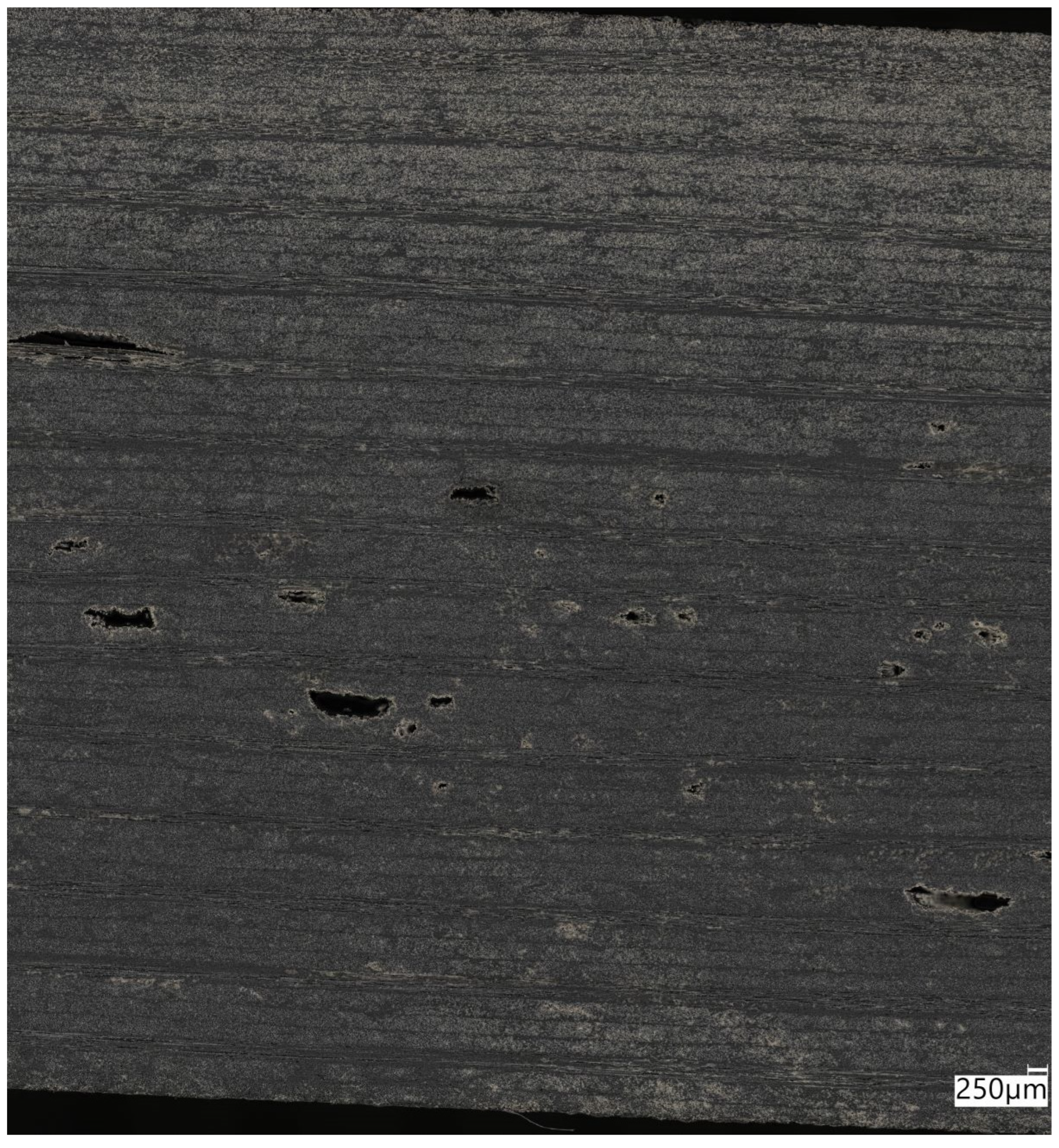
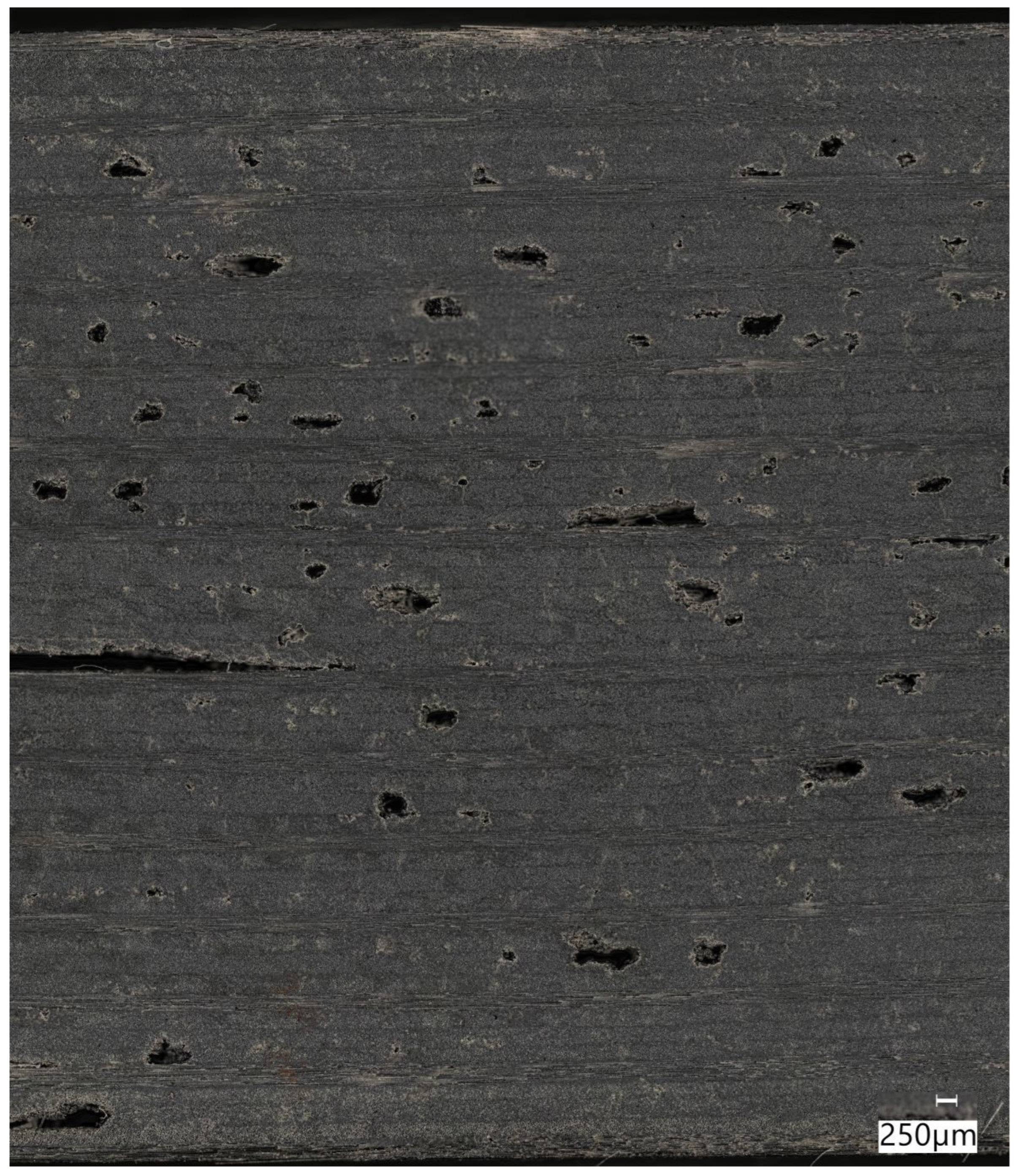
For comparison to the vehicle component laminates in the prior section, Figure 3, Figure 4, Figure 5 and Figure 6 show cross-sections of full-thickness—16 mm (5/8 in)—flat panels, each fabricated from entirely GF/PPS+CB or CF/PPS plies. These flat panels were consolidated in the Monarch press using the same heating rate, peak part temperature and pressure, and cooling rate, as the vehicle components consolidated in the thermoforming press. The flat GF/PPS+CB panel in Figure 3 does not show the interlaminar macrocracks and macrovoids visible in the curved region of Figure 1 and Figure 2, but widespread transverse intralaminar microcracks and interlaminar microvoids remain throughout the laminate. Note the panel’s ply delamination due to waterjet cutting at the top of Figure 3. This delamination during cutting is atypical for a sufficiently consolidated laminate. Figure 4 is a closeup of the GF/PPS+CB laminate of Figure 3, clearly showing transverse intralaminar microcracks and interlaminar microvoids, which could be the origin of the interlaminar macrocracks observed in Figure 1 and Figure 2.
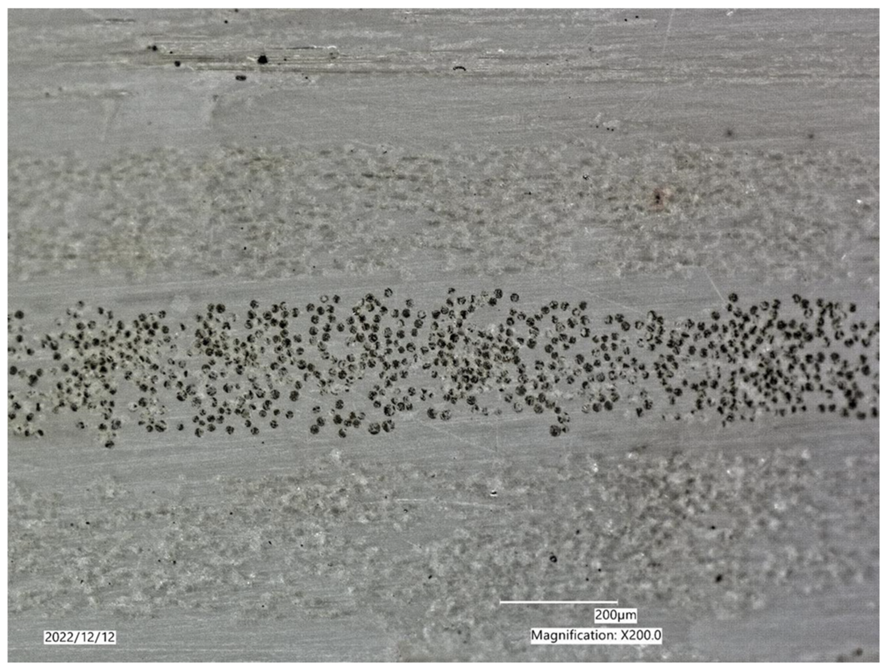
In contrast, the CF/PPS panel in Figure 5, fabricated under equivalent processing conditions, showed no signs of micro-/macrocracking, micro-/macrovoids, or delamination of its top ply. Figure 6 is a closeup of a matrix-rich area of Figure 5, confirming no evidence of matrix defects present in the CF/PPS flat laminate.
Based on these results, it was obvious that the GF/PPS+CB laminates, whether flat or curved, had fundamental matrix quality concerns that were not apparent in the CF/PPS laminates when these materials were processed at the same temperature and pressure. Consolidating an entirely CF/PPS laminate prototype vehicle component was the preferred manufacturing solution to avoid the defects in GF/PPS+CB, but that was not within program scope, as the quantity of purchased CF/PPS material was significantly less than GF/PPS+CB, largely due to its nearly 3× higher cost. Further, GF laminates offer higher strain to failure than an equivalent carbon laminate, and an all-CF/PPS component was not a cost-feasible solution for the vehicle application. Thus, an acceptable composite vehicle component—which meant one comprised substantially of GF/PPS—but with sufficient laminate quality, was still needed.

3.2.2. GF/PPS-NA at 288 °C (550 °F) and 690 kPa (100 psi)

Coincident with results from the initial component fabrication trials in Figure 1 and Figure 2, the material manufacturer was queried about GF/PPS+CB’s additives, and they stated that the only additive in GF/PPS+CB is carbon black as a colorant. Consequently, GF/PPS tape without colorant was requested to investigate whether carbon black was causing the observed results. The manufacturer had only small sample quantities of 60% and 70% fiber content by weight GF/PPS-NA tapes in stock. Unfortunately, the quantities were insufficient to perform a consolidation trial of a full-size vehicle component, and additional quantities would not be made available to support the program deliverable. However, an adequate quantity was acquired to perform a few flat panel consolidation trials at full laminate thickness (16 mm [5/8 in]).
Both 60% and 70% GF/PPS-NA were acquired so that the fiber volume fraction (Vf) could be held constant when comparing GF- and CF-reinforced PPS. Due to differences in density of GF and CF, the 70% (by weight) GF/PPS-NA has an essentially equivalent Vf to 60% (by weight) CF/PPS, and the Vf of the 60% (by weight) GF/PPS-NA is equivalent to 60% (by weight) GF/PPS+CB. Since both 70% GF/PPS-NA and 60% CF/PPS have a natural PPS matrix (no CB colorant/additive) and their fiber volumes are equivalent, the only difference is the fiber type/filament diameter. The only difference between 70% and 60% GF/PPS-NA is the Vf. The only difference between 60% GF/PPS-NA and 60% GF/PPS+CB is the inclusion of carbon black matrix colorant. Relative comparison of these materials enabled an understanding of whether Vf, fiber type/filament diameter, or carbon black additive was a primary factor influencing the observed matrix defect results.
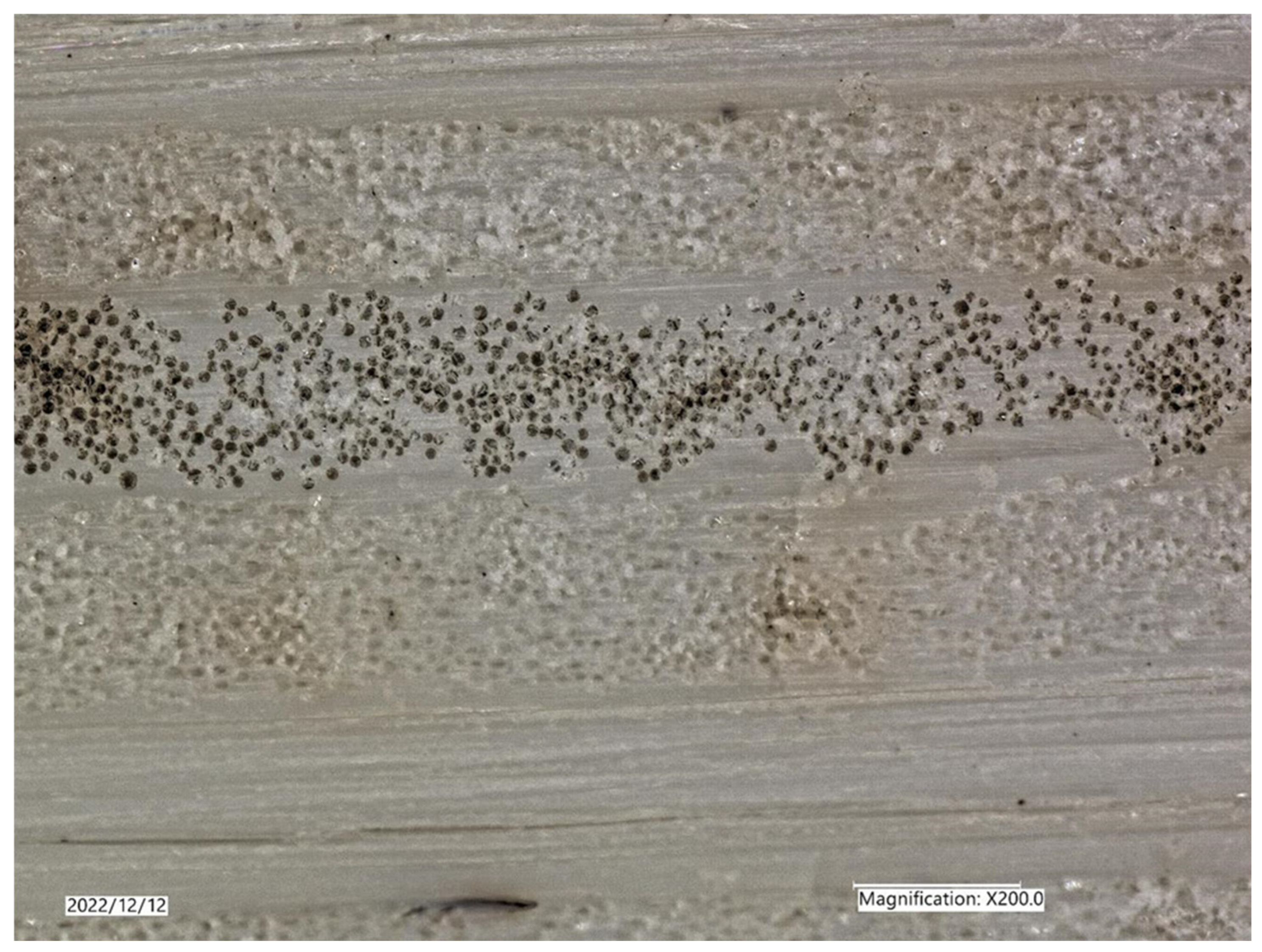
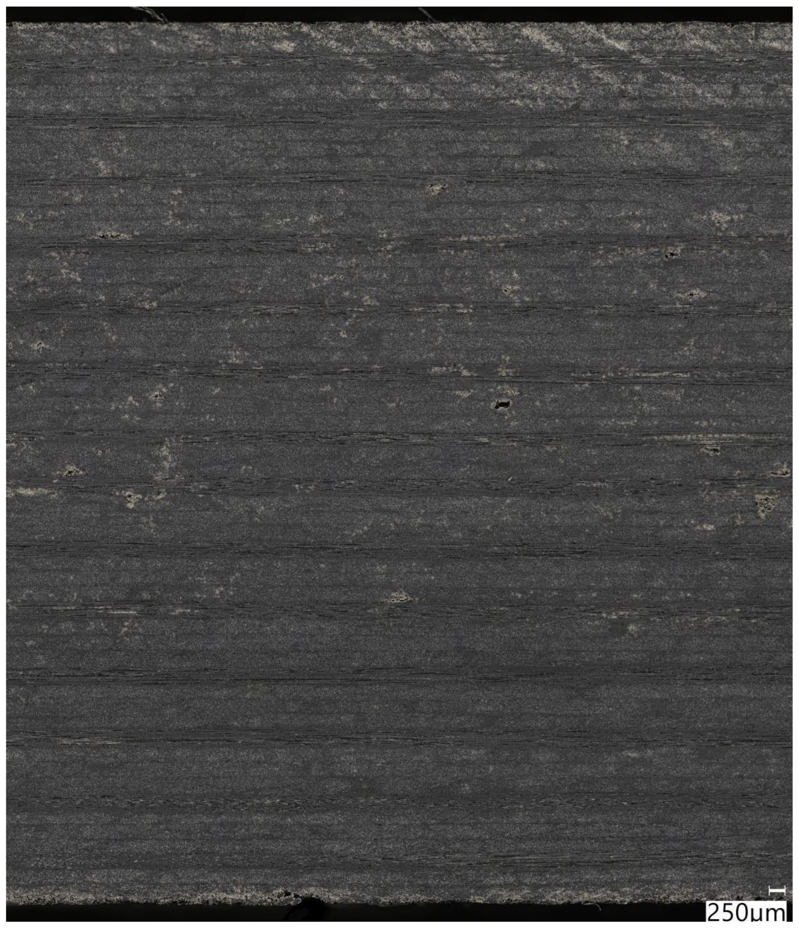
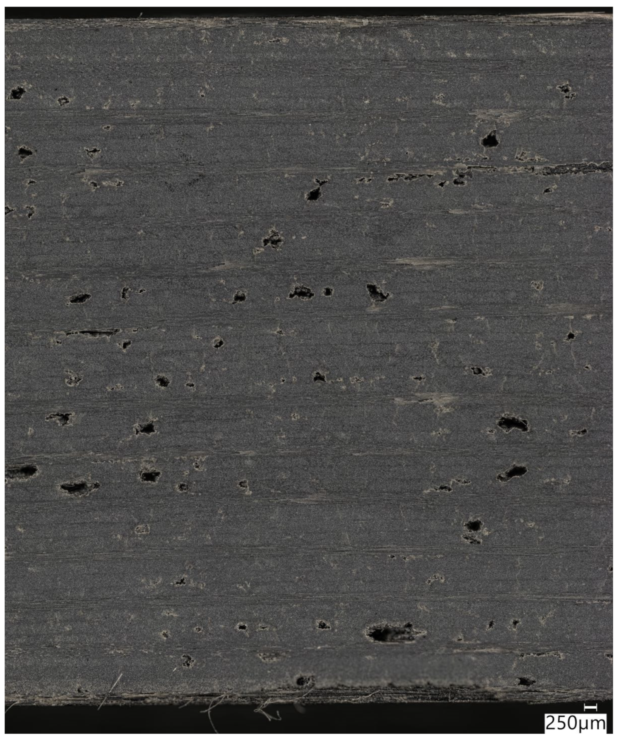
Figure 7 and Figure 8 show microscopic cross-sections of full-component-thickness flat panels fabricated in the Monarch press using equivalent processing parameters from prior consolidations—288 °C (550 °F), 690 kPa (100 psi) pressure, and cooling rate—for 60% GF/PPS-NA and 70% GF/PPS-NA, respectively. No evidence of matrix defects (micro-/macrocracks or micro-/macrovoids) were apparent in the 60% and 70% GF/PPS-NA flat laminates. Note, the black-colored fiber ends shown in Figure 7 and Figure 8 are resultant from the microscopy polishing equipment’s surface.

3.2.3. GF/PPS+CB at 340 °C (645 °F) and 580 kPa (84 psi)

Based on prior results, producing a prototype composite vehicle component within this work from CF/PPS and GF/PPS-NA would be ideal but was not feasible due to a lack of material availability. Consequently, if a PPS composite vehicle component was going to be fabricated in this effort, it would need to use GF/PPS+CB as its core. The last set of trials performed within this work investigated whether heating GF/PPS+CB to the literature-recommended PPS processing temperature of 340 °C (645 °F) would produce acceptable laminate matrix quality. Due to heating well above PPS’s melt temperature, a 305 mm × 305 mm (12 in × 12 in) steel closed mold was used to constrain matrix flow and fiber wash during these processing evaluations.
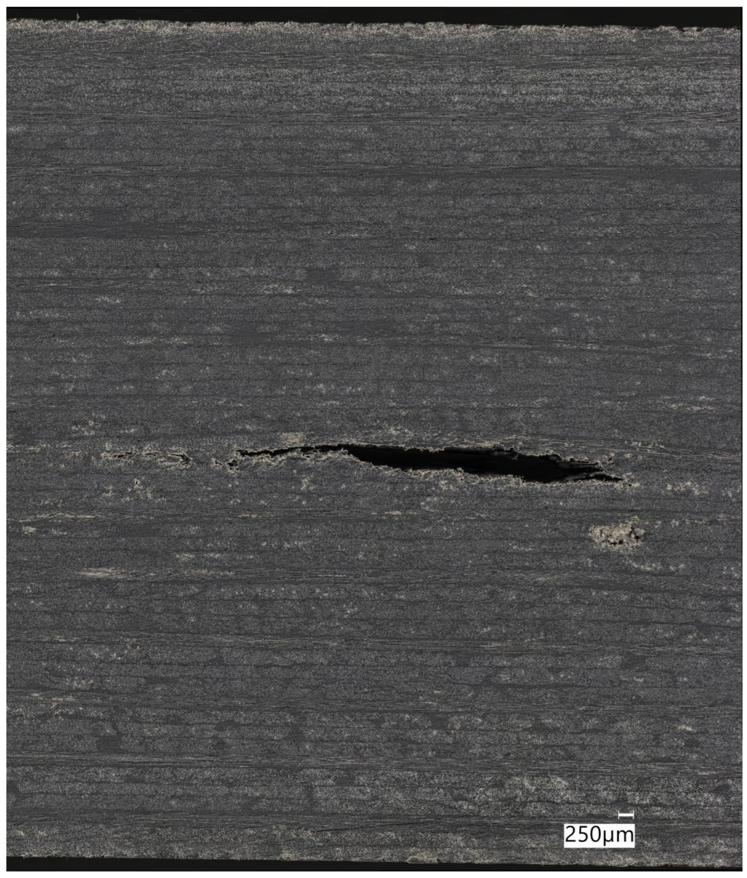
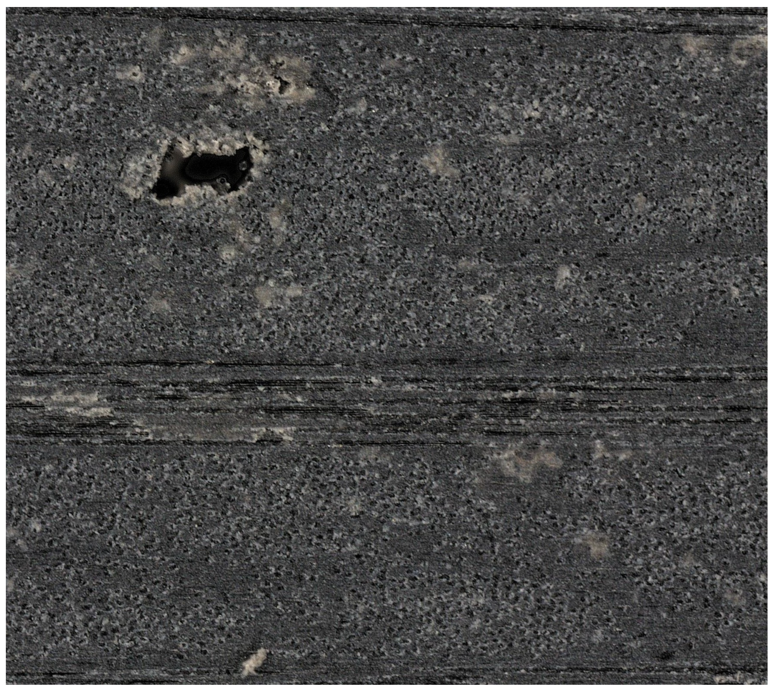
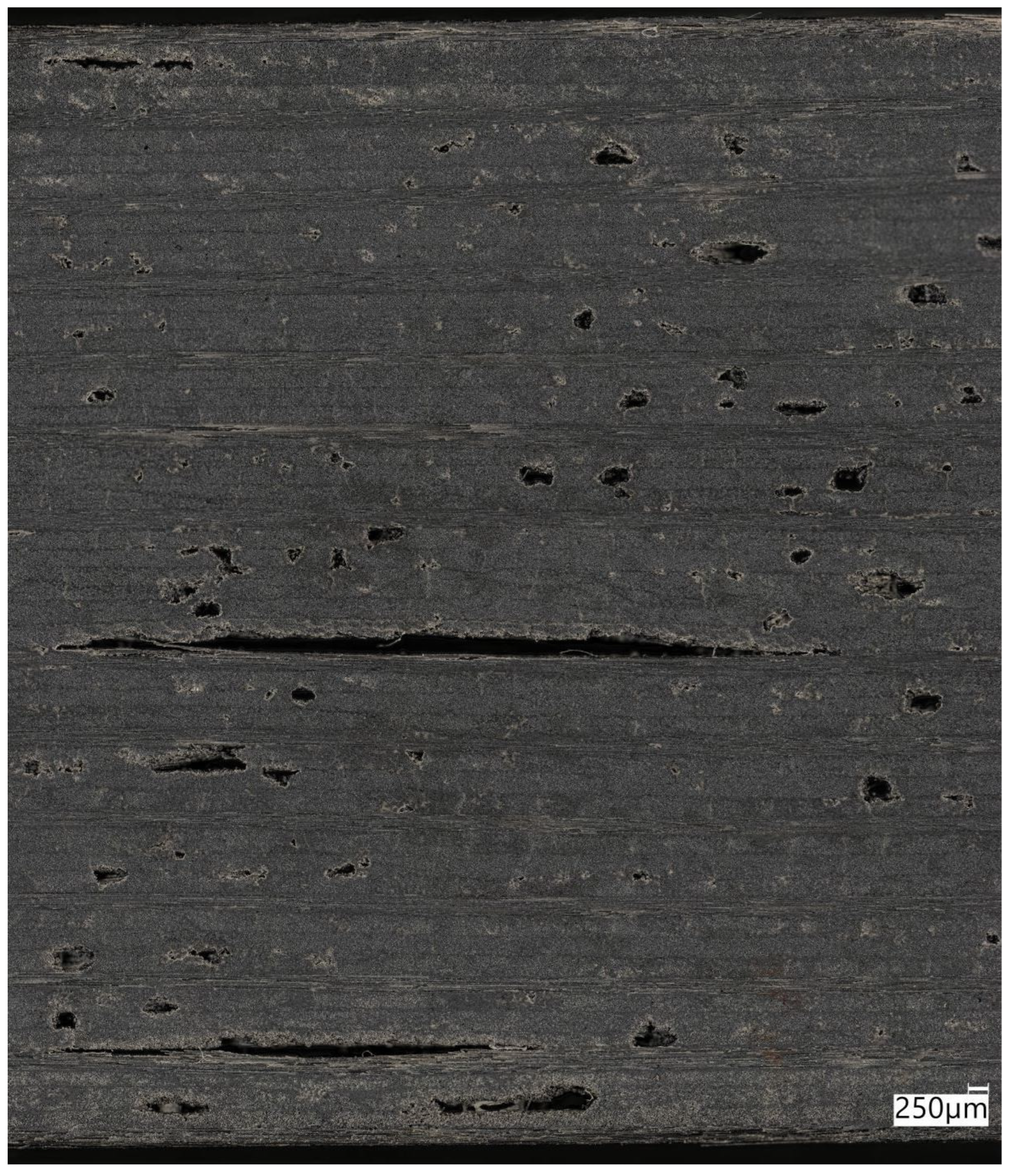
Two 356 mm × 356 mm (14 in × 14 in) flat panels of full-thickness GF/PPS+CB laminate were preconsolidated at 288 °C (550 °F) and 690 kPa (100 psi). Laminate quality was confirmed to be analogous to Figure 3 and Figure 4, i.e., pervasive microcracking but no macrovoids. These panels were trimmed to 305 mm × 305 mm (12 in × 12 in) using a waterjet. Each preconsolidated panel was then processed individually in the closed mold using the Monarch press. Panels were heated to a minimum of 340 °C (645 °F), as measured by thermocouples embedded in the laminate’s midplane on two opposite sides. Once at temperature, panels dwelled for 30 min and were then consolidated at 580 kPa (84 psi). Cooling started immediately after full pressure application. Panel #1 was cooled at an average rate of 9.3 °C/min (16.7 °F/min). Panel #2 was cooled at an average rate of 0.3 °C/min (0.6 °F/min). Figure 9, Figure 10 and Figure 11 show typical cross-sections of Panel #1 in three regions across its width on the same cutting plane. Interlaminar and transverse intralaminar microcracks were not visible anywhere, as shown in Figure 12, but micro- to macro-size voids were distributed throughout the panel, though mostly within the middle 50% of plies through its thickness. There was noticeable difference between regions in the panel. Some regions had a mixture of macro- and microvoids (Region A), other regions had almost no macrovoids but extensive microvoids (Region B), while other regions had microvoids and very large macrovoids (Region C).
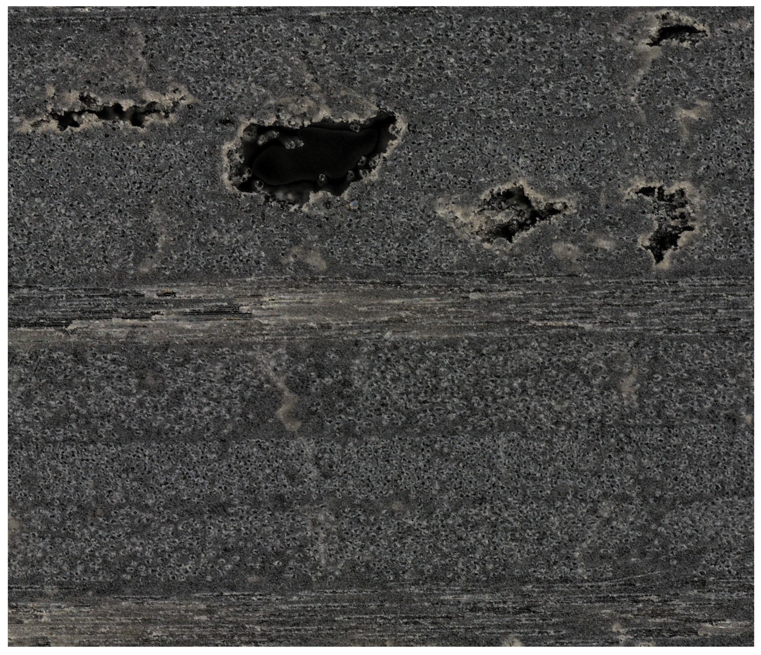
Figure 13, Figure 14 and Figure 15 show typical cross-sections of Panel #2 in three regions across its width on the same cutting plane. Figure 16 shows that transverse intralaminar microcracking was present within Panel #2 but in a far less quantity than in Figure 2 and Figure 3; the panel was mostly laden with macrovoids and microvoids, which were distributed uniformly along its length and through its thickness.

4. Discussion

Phenomena that could potentially explain the results observed in the GF/PPS+CB laminates include the effects of a very slow cooling rate, maximum processing temperature, carbon black nucleation increasing the PPS matrix’s percentage crystallinity, and/or percentage crystallinity effects on polymer shrinkage.
As stated, the cooling rate in the thermoforming press during component consolidations averaged approximately 0.3 °C/min (0.6 °F/min). Cooling rates (and commensurate properties) reported in [10], for laminates without carbon black, indicate that the cooling rates used herein do not alone explain the unexpected results observed in the GF/PPS+CB. Comparing the results of Figure 6 to Figure 8 for CF/PPS to 70% GF/PPS-NA, and Figure 7 to Figure 8 for 60% GF/PPS-NA to 70% GF/PPS-NA, there is no evidence that the fiber type/filament diameter or Vf are the causes of the observed matrix defects in Figure 3 and Figure 4 for GF/PPS+CB. Comparison of Figure 4 to Figure 7 for 60% GF/PPS+CB to 60% GF/PPS-NA—where the only difference between the two materials is the inclusion of carbon black matrix colorant—points to carbon black as the root cause for the observed matrix defects. As a reminder, all of the laminates shown in Figure 3, Figure 4, Figure 5, Figure 6, Figure 7 and Figure 8 had identical processing conditions. It is hypothesized that matrix shrinkage, due to substantially higher PPS crystallinity than is found in the typical literature on the subject caused by enhanced crystal nucleation due to presence of the carbon black matrix additive, is the reason for the laminate matrix defects herein. Crystallinity was not directly measured (e.g., via DSC or XRD), so the hypothesis of enhanced crystal nucleation caused by the carbon black is inferred from observations and experience. Even when the GF/PPS+CB was heated to a maximum processing temperature reported to eliminate all molecular order and crystallites, the results are similar, in that extensive micro- and macrovoids are produced upon cooling (at both fast and slow cooling rates), though at a fast cooling rate the intralaminar microcracking seems to have been eliminated. The fast cooling rate made a noticeable positive difference in matrix quality compared to the slow cooling rate but was far from sufficient to produce a laminate of acceptable quality for the intended application.
The results from processing GF/PPS+CB were unexpected, and program limitations precluded further investigation into potential root cause(s) of the observed results. To confirm this work’s hypothesis that carbon black caused abnormally high crystallinity, which, in turn, caused excessive shrinkage and the observed micro-/macrocracks, percentage crystallinity of the various fabricated components and panels should have been measured for correlation to their processing parameters (e.g., peak temperature, cooling rate, natural matrix vs carbon black matrix, etc.).
More research is needed to quantify the observed results, with the overall objective of determining whether a suitable process could be identified which enables use of GF/PPS+CB in thick load-critical structures without the undesirable matrix defects. Conducting this research could also increase understanding of other semicrystalline polymers, whether continuous fiber-reinforced tapes, or milled-fiber-reinforced polymers for additive manufacturing or injection molding.

5. Conclusions

The results of this work show that CF/PPS and GF/PPS-NA are both capable of being processed using compression forming at PPS’s DSC-derived melt temperature, combined with slow cooling rates, without inducing voids, intralaminar microcracking, and/or interlaminar macrocracks. In contrast, using the same processing conditions, GF/PPS+CB laminates were unable to produce acceptable laminate quality for the intended application. Furthermore, compression forming of preconsolidated GF/PPS+CB panels at 340 °C (645 °F) with a fast cool-down rate did not produce markedly improved laminate matrix quality compared to slower cooling rates. However, the trials performed within this work were limited, and additional research is needed to investigate the effect of additives, such as colorants, on the processing of thick continuous fiber-reinforced thermoplastic laminates.

Author Contributions

Conceptualization, B.N.D., D.F.E.J., R.J.H. and A.Q.S.; Methodology, B.N.D.; Validation, B.N.D.; Investigation, W.B.Y., D.H.P., S.M.N., Q.O.T. and B.N.D.; Resources, J.R.R. and B.N.D.; Original draft preparation and writing, B.N.D.; Draft review, B.N.D., D.F.E.J., W.B.Y., D.H.P., S.M.N., Q.O.T., J.R.R., R.J.H. and A.Q.S.; Draft editing, B.N.D., D.F.E.J. and R.J.H.; Visualization, D.H.P., W.B.Y. and B.N.D.; Supervision, B.N.D., D.F.E.J. and J.R.R.; Project administration, J.R.R.; Funding acquisition, D.F.E.J. All authors have read and agreed to the published version of the manuscript.

Funding

This research was funded through the National Center for Manufacturing Sciences (NCMS), award number 202115-142025.

Data Availability Statement

Requests to access the datasets presented in this article should be directed to benjamin.dwyer@composites.maine.edu.

Conflicts of Interest

The authors declare no conflicts of interest. The funders had no role in the design of the study; in the collection, analyses, or interpretation of data; in the writing of the manuscript; or in the decision to publish the results.

Abbreviations

The following abbreviations are used in this manuscript:
PPSPolyphenylene sulfide
GFE-glass fiber
CFCarbon fiber
CBCarbon black
NANatural PPS polymer (no matrix additive)
DSCDifferential scanning calorimetry
DMADynamic mechanical analysis
FSTFlammability, smoke generation, and toxicity
PETPolyethylene terephthalate
PETGPolyethylene terephthalate glycol
PCPolycarbonate
PPPolypropylene
TgGlass transition temperature
HDTHeat deflection temperature
TmMelt temperature
FTIRFourier transform infrared spectroscopy
VfFiber volume
ATLAutomated tape layup
RTRoom temperature

References

  1. Zhao, D.; Li, Z.; Liu, W.; Li, T.; Yue, G.; Pan, L. Crystallization mechanism and mechanical properties of CF/PPS thermoplastic composites manufactured by laser-assisted automated fiber placement. J. Comp. Mat. 2023, 57, 49–61. [Google Scholar] [CrossRef]
  2. Spruiell, J.E.; Janke, C.J. A review of the measurement and development of crystallinity and its relation to properties in neat poly(phenylene sulfide) and its fiber reinforced composites. Mater. Sci. Eng. 2005. [Google Scholar] [CrossRef]
  3. Nohara, L.B.; Nohara, E.L.; Moura, A.; Gonçalves, J.M.P.; Costa, M.L.; Rezende, M.C. Study of crystallization behavior of poly(phenylene sulfide). Polímeros 2006, 16, 104–110. [Google Scholar] [CrossRef]
  4. Knox, M. Continuous fiber reinforced thermoplastic composites in the automotive industry. Auto. Comp. Conf. 2001. [Google Scholar]
  5. Zhao, L.; Yu, Y.; Huang, H.; Yin, X.; Peng, J.; Sun, J.; Huang, L.; Tang, Y.; Wang, L. High-performance polyphenylene sulfide composites with ultra-high content of glass fiber fabrics. Comp. Part B Eng. 2019, 174, 106790. [Google Scholar] [CrossRef]
  6. Kull, H. Airbus to fly with PPS: Plastic composites replacing aluminum in the wings. KU Kunststoffe Plast Eur. 2002, 92, 28–29. [Google Scholar]
  7. Brosius, D. Extra large by any measure. High-Perform. Compos. 2002, 10, 14–23. [Google Scholar]
  8. Sloan, J. Inside a thermoplastic composites hotbed. High-Perform. Compos. 2014, 22, 42. [Google Scholar]
  9. Anon. Polyphenylene sulfide protects military aircraft from ice chunks. Plast. Today 2013. Available online: https://www.plasticstoday.com/materials/pps-composite-features-in-airbus-military-plane (accessed on 25 November 2025).
  10. Oshima, S.; Higuchi, R.; Kato, M.; Minakuchi, S.; Yokozeki, T.; Aoki, T. Cooling rate-dependent mechanical properties of polyphenylene sulfide (PPS) and carbon fiber reinforced PPS (CF/PPS). Comp. Part A App. Sci. Manuf. 2023, 164, 107250. [Google Scholar] [CrossRef]
  11. Mei, Z.; Chung, D.D.L. Cold-crystallization of polyphenylene sulfide, studied by measuring the electrical resistance of a carbon-fibre polyphenylene-sulfide-matrix composite. Polym. Polym. Compos. 2000, 8, 319–324. [Google Scholar]
  12. D’ilario, L.; Martinelli, A. Glass transition and the origin of poly(p-phenylene sulfide) secondary crystallization. Eur. Phys. J. E 2006, 19, 37–45. [Google Scholar] [CrossRef] [PubMed]
  13. Siddiqui, H.; Ali, U.; Sahito, I.A.; Malik, S.A.; Sun, K.C.; Mengal, N. Comprehensive review of carbon materials as counter electrodes in dye-sensitized solar cells: Efficiency assessment and deposition methods. Mater. Sci. Semicond. Process. 2024, 172, 108074. [Google Scholar] [CrossRef]
  14. Horrocks, A.R.; Mwila, J. The effect of carbon black on the physical properties of polypropylene geotextile tapes. In Geosynthetics: Applications, Design and Construction; Termaat, R.J., de Groot, M.B., den Hoedt, G., Eds.; CRC Press: Boca Raton, FL, USA, 1996; pp. 851–858. ISBN 9054108363. [Google Scholar]
  15. Lin, Y.; Zhou, J.E. Spruiell. In Proceedings of the Society of Plastics Engineers ANTEC Conference, Montreal, QC, Canada, 5–9 May 1991; p. 1950. [Google Scholar]
  16. Brady, D.G. The Crystallinity of Poly(phenylene Sulfide) and Its Effect on Polymer Properties. J. App. Poly. Sci. 1976, 20, 2541–2551. [Google Scholar] [CrossRef]
  17. Lee, T.H.; Boey, F.Y.C.; Khor, K.A. On the determination of polymer crystallinity for a thermoplastic PPS composite by thermal analysis. Comp. Sci. Technol. 1995, 53, 259–274. [Google Scholar]
  18. Benedetti, L.; Brulé, B.; Decreamer, N.; Evans, K.E.; Ghita, O. Shrinkage behaviour of semi-crystalline polymers in laser sintering: PEKK and PA12. Mater. Des. 2019, 181, 107906. [Google Scholar] [CrossRef]
  19. Golzar, M.; Sinke, J.; Abouhamzeh, M. Novel thermomechanical characterization for shrinkage evolution of unidirectional semi-crystalline thermoplastic prepregs (PPS/CF) in melt, rubbery and glassy states. Comp. Part A 2022, 156, 106879. [Google Scholar] [CrossRef]
Figure 1. Hybrid-layup vehicle component consolidation showing bridged plies and large interlaminar cracks (macrocracks). Consolidation at 288 °C (550 °F) and 690 kPa (100 psi) part pressure.
Jcs 09 00669 g001
Figure 2. All GF/PPS+CB laminate vehicle component consolidation without bridged plies. Intralaminar microcracks, interlaminar macrocracks, and voids are pervasive throughout the laminate. Consolidation at 288 °C (550 °F) and 690 kPa (100 psi) part pressure.
Jcs 09 00669 g002
Figure 3. All GF/PPS+CB flat panel consolidated at 288 °C (550 °F) and 690 kPa (100 psi) part pressure.
Jcs 09 00669 g003
Figure 4. Close-up of GF/PPS+CB laminate of Figure 3.
Jcs 09 00669 g004
Figure 5. All CF/PPS flat panel consolidated at 288 °C (550 °F) and 690 kPa (100 psi) part pressure.
Jcs 09 00669 g005
Figure 6. Close-up of CF/PPS laminate of Figure 5.
Jcs 09 00669 g006
Figure 7. All GF/PPS-NA flat panel, 60% glass fiber, processed at 288 °C (550 °F) and 690 kPa (100 psi).
Jcs 09 00669 g007
Figure 8. All GF/PPS-NA flat panel, 70% glass fiber, processed at 288 °C (550 °F) and 690 kPa (100 psi).
Jcs 09 00669 g008
Figure 9. GF/PPS+CB Panel #1 Region A; preconsolidated at 288 °C (550 °F) and 690 kPa (100 psi); subsequently processed at 340 °C (645 °F), 580 kPa (84 psi), and 9.3 °C/min (16.7 °F/min) cooling rate.
Jcs 09 00669 g009
Figure 10. GF/PPS+CB Panel #1 Region B; preconsolidated at 288 °C (550 °F) and 690 kPa (100 psi); subsequently processed at 340 °C (645 °F), 580 kPa (84 psi), and 9.3 °C/min (16.7 °F/min) cooling rate.
Jcs 09 00669 g010
Figure 11. GF/PPS+CB Panel #1 Region C; preconsolidated at 288 °C (550 °F) and 690 kPa (100 psi); subsequently processed at 340 °C (645 °F), 580 kPa (84 psi), and 9.3 °C/min (16.7 °F/min) cooling rate.
Jcs 09 00669 g011
Figure 12. Close-up of GF/PPS+CB Panel #1 Region B of Figure 10; no intralaminar microcracks were visible in the panel.
Jcs 09 00669 g012
Figure 13. GF/PPS+CB Panel #2 Region A; preconsolidated at 288 °C (550 °F) and 690 kPa (100 psi); subsequently processed at 340 °C (645 °F), 580 kPa (84 psi), and 0.3 °C/min (0.6 °F/min) cooling rate.
Jcs 09 00669 g013
Figure 14. GF/PPS+CB Panel #2 Region B; preconsolidated at 288 °C (550 °F) and 690 kPa (100 psi); subsequently processed at 340 °C (645 °F), 580 kPa (84 psi), and 0.3 °C/min (0.6 °F/min) cooling rate.
Jcs 09 00669 g014
Figure 15. GF/PPS+CB Panel #2 Region C; preconsolidated at 288 °C (550 °F) and 690 kPa (100 psi); subsequently processed at 340 °C (645 °F), 580 kPa (84 psi), and 0.3 °C/min (0.6 °F/min) cooling rate.
Jcs 09 00669 g015
Figure 16. Close-up of GF/PPS+CB Panel #2 Region A of Figure 13 showing transverse intralaminar microcracking.
Jcs 09 00669 g016
Disclaimer/Publisher’s Note: The statements, opinions and data contained in all publications are solely those of the individual author(s) and contributor(s) and not of MDPI and/or the editor(s). MDPI and/or the editor(s) disclaim responsibility for any injury to people or property resulting from any ideas, methods, instructions or products referred to in the content.