Article

Fatigue Damage Suppression by Ply Curving Termination in Covered Composite Ply Drop-Off

Graduate School of Engineering, The University of Tokyo, Tokyo 113-8656, Japan
*
Author to whom correspondence should be addressed.
J. Compos. Sci. 2025, 9(10), 523; https://doi.org/10.3390/jcs9100523
Submission received: 21 July 2025 / Revised: 22 September 2025 / Accepted: 24 September 2025 / Published: 1 October 2025

Abstract

Ply Curving Termination (PCT) is an effective method to suppress stress concentration at composite ply drop-offs by locally curving the reinforcing fibers to reduce the stiffness. A previous study by the authors confirmed that PCT can suppress fatigue delamination failure in composite ply drop-off. However, the specimens used were external ply drop-offs without cover plies and did not reflect practical structural configurations. Following the basic study, this current study evaluated the fatigue damage suppression characteristic of PCT in practically relevant internal ply drop-offs with cover plies. Finite element analysis, fatigue testing, and detailed observation of the failure process using X-ray CT showed that PCT is effective in suppressing fatigue failure of internal ply drop-offs. In particular, delamination propagation from matrix cracks along the curving fibers, a weak point of PCT, is suppressed in the external ply drop-off. Finite element analysis indicated the importance of stress transfer from the cover ply to the ply drop-off, confirming that the fatigue damage suppression effect of PCT is enhanced in practical composite ply drop-off configurations.

1. Introduction

In a lightweight composite aerostructure, the laminate thickness is changed according to the applied load, and tapered laminates are widely used [1,2,3,4,5]. There are two types of tapered laminates with different ply drop-off positions, as shown in Figure 1: external ply drops, in which the ply is dropped-off externally, and internal ply drops, in which the ply is dropped-off internally. Load in the base laminate is transferred to the dropped ply by out-of-plane shear stresses at the interfaces of the dropped ply. It is well known that the ply drop-off causes stress concentration due to the shape discontinuity, and delamination can occur from the edge of the dropped ply [6]. From the perspectives of lightweighting and manufacturing, it is desirable to use a steep taper. However, increasing the number of plies dropped at a single location or reducing the spacing between adjacent ply drop-offs has been found to reduce the strength of the tapered laminate [7,8]. Therefore, a gentle taper is currently used, which is a barrier to further weight reduction in composite structures.
By introducing a mechanism to suppress delamination from the ply drop-offs, a steeper taper can be used. The laminate thickness can be designed with a high degree of freedom, leading to lighter composite structures. Therefore, many studies have been conducted on ideas to suppress delamination [9,10,11,12,13,14]. One approach is to optimize the order in which plies are dropped off. Fish et al. confirmed the effectiveness of arranging ply drop-offs in a stepped configuration and of overlapping the edges of dropped plies [15]. Another approach is to modify the materials used in the laminate or to introduce additional materials [16,17]. Thin-ply prepreg enhanced the static tensile strength [11,18], and addition of nanoclay to the matrix resin improved the fatigue life [19]. The other interesting approach is to alter the characteristics and shape of the dropped ply edges. Researchers at the University of Bristol chamfered the edges of dropped ply to reduce the geometry discontinuity [20], and have demonstrated improvements in various mechanical properties, including tension, compression, fatigue, and impact resistance [21,22,23,24].
The authors’ research group has also proposed one approach that leverages the anisotropy of composite materials to alter the characteristics of ply edge, called Ply Curving Termination (PCT) [25,26]. PCT locally changes the fiber direction at the edge of the dropped ply (Figure 2). The longitudinal stiffness of the dropped ply edge is significantly decreased, suppressing the stress concentration at the ply drop-off. PCT is simple, requiring no additional materials, and can be combined with other approaches as described above.
In order to improve the technical maturity of PCT, evaluations under practically relevant fatigue conditions are essential [27,28,29]. In our previous work [30], the fatigue properties of PCT were evaluated using the simplest form, the external ply drop-off specimen (Figure 1a). The results clearly showed that PCT delays the onset of initial damage and also significantly increases the cycles to final failure. However, for practical structures, internal ply drop-off with a cover ply on top of the ply drop-off is commonly used (Figure 1b). Therefore, it is necessary to confirm that PCT is effective in improving fatigue properties of external ply drop-offs. It is important to note that in our previous test using the external ply drop-off specimens [30], the fatigue failure modes transitioned and fatigue properties changed significantly with loading level. Specifically, delamination propagated from the ply drop-off under low loading conditions, whereas under high loading conditions, delamination propagated from the inside of the cracks that formed along the curving fibers (Figure 2). This result implies that detailed observation of the fracture process is necessary to demonstrate the effectiveness of PCT at internal ply drop-offs.
This study first calculates the stress differences between the two forms of ply drop-off (i.e., external and internal) by finite element analysis to examine the effectiveness of PCT at internal ply drop-off. Next, fatigue specimens are fabricated and the process from the onset of initial damage to final failure is evaluated using X-ray CT at high and low loading levels.
Figure 2. Schematic of PCT and transition of fatigue damage mode in external ply drop-off [30].
Jcs 09 00523 g002

2. Finite Element Analysis

2.1. Finite Element Model

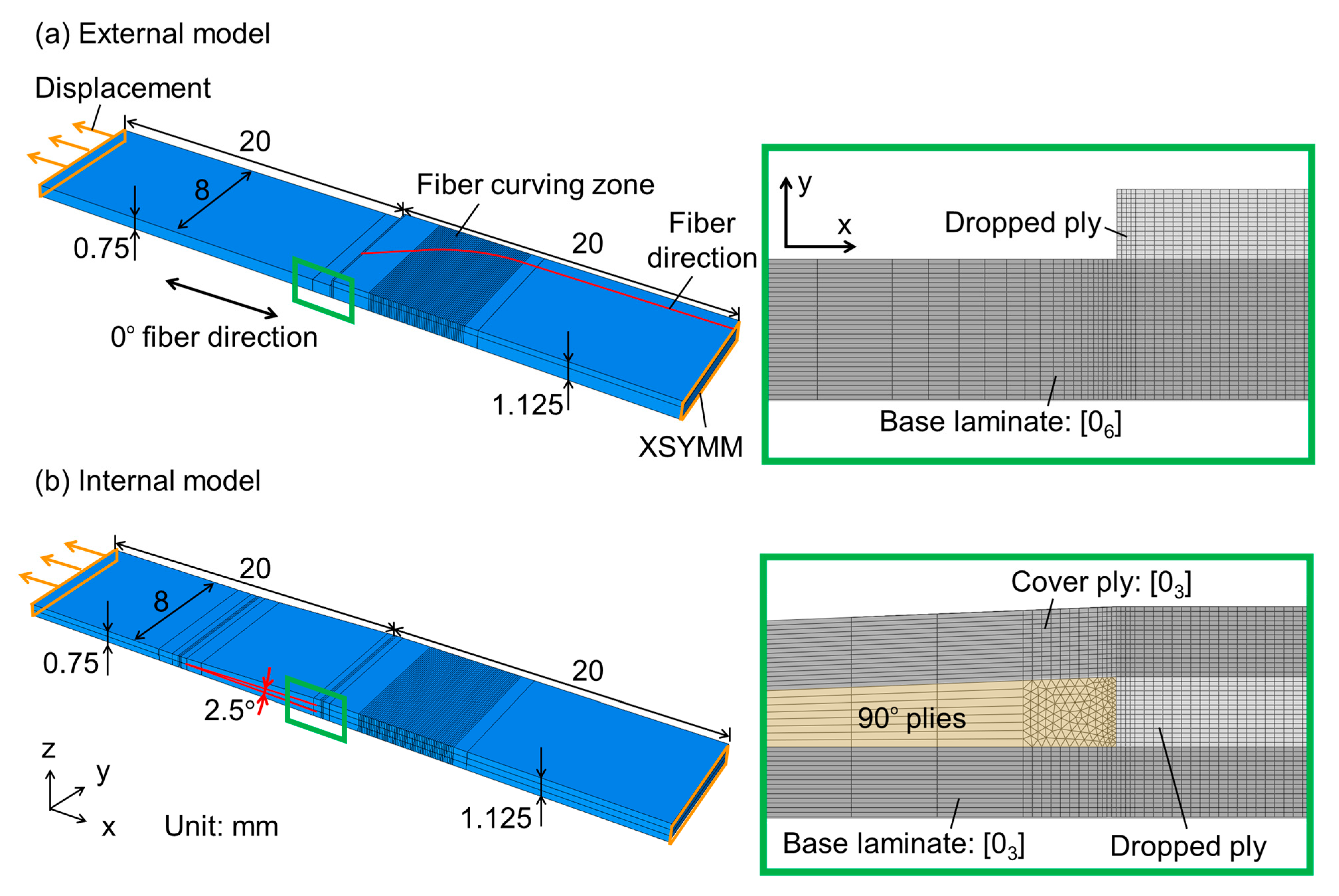
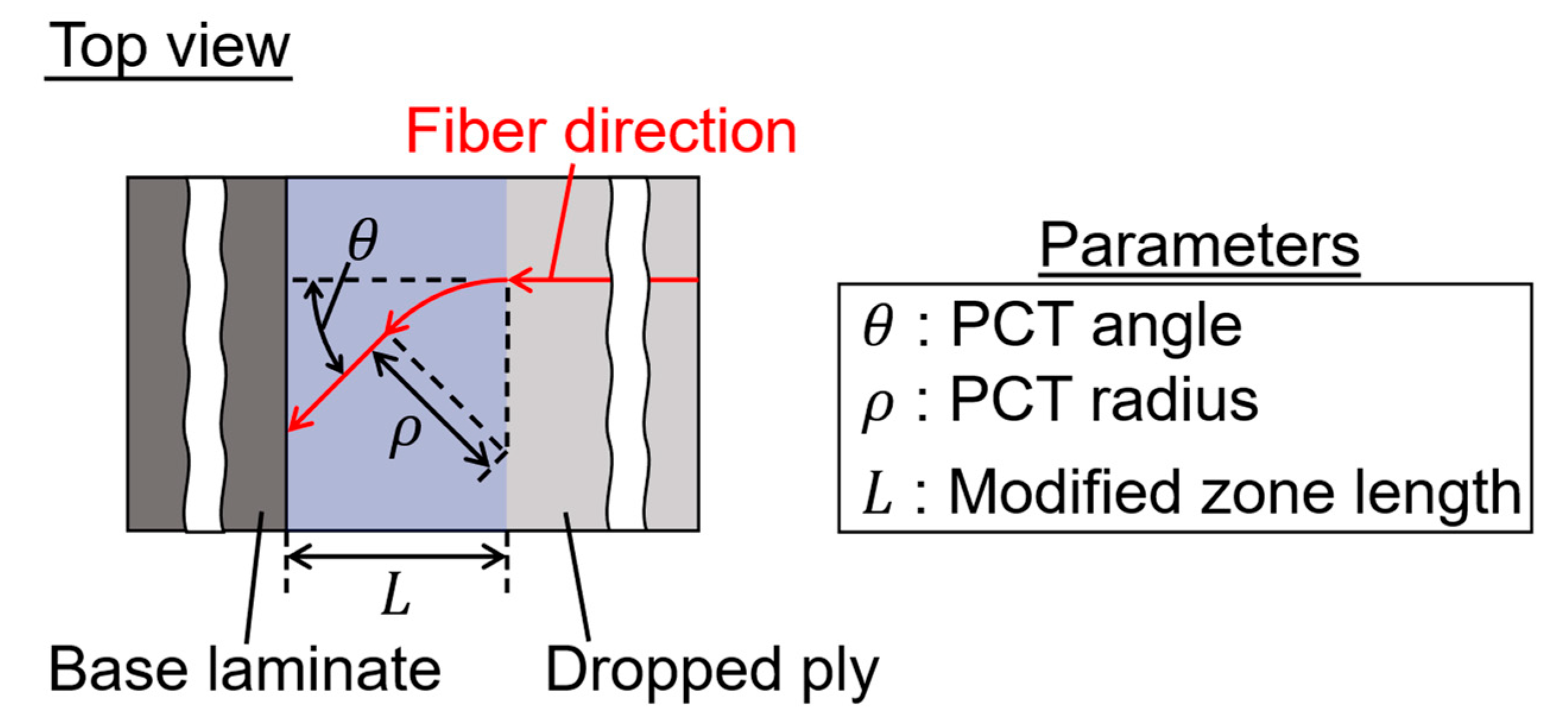
The out-of-plane stress at the interfaces of the two kinds of tapered laminates, external and internal ply drop-offs (Figure 1), under tensile loading was calculated. The specimen geometry was the same as that of the tensile fatigue experiment described later. The stacking sequence of the External model (Figure 3a) was [06] for the base laminate and [03] for the dropped ply. In the Internal model (Figure 3b), the base laminate, the dropped ply and the covered ply all had a stacking sequence of [03]. So, both the External model and the Internal model had 9 plies in the thick part, and 3 plies were dropped-off at one location, resulting in 6 plies in the thin part. The thickness of one ply was 0.125 mm. The taper angle of the Internal model was 2.5°. Two types of models were created for both the External and Internal models: Normal model with a 0° fiber direction at the end of the dropped ply and PCT45 model with 45° PCT angle. The PCT geometry parameters including the PCT angle are shown in Figure 4. In this study, the PCT radius and modified zone length were set to 8 mm and 8 mm, respectively. In a region where the fiber direction of the dropped ply changes (fiber curving zone), the model was divided into small parts at 0.1 mm intervals in the x-direction, and the corresponding fiber direction was set for each part to model PCT. The material was carbon fiber/epoxy (T700SC/2592, Toray Industries, Inc., Tokyo, Japan), and its material properties are given in Table 1. The triangular column space between the base laminate and the cover ply at the end of the ply drop-off was filled with 90° plies. The edge of the thick section was fixed by the x-symmetry boundary condition, and uniform displacement in the x-direction was applied to the edge of the thin section so that the average tensile stress in the thin section was 1000 MPa (0.8% tensile strain in the thin section). Abaqus 2023 (Dassault Systems Inc., Vélizy-Villacoublay, France) was used to perform static geometric nonlinear analysis. The models were meshed with hexahedral first-order elements (C3D8) except for the edges of the triangular column space between the base laminate and the cover ply in the Internal model, where 6-node linear triangular prism elements (C3D6) were used. One ply was divided by five solid elements in the thickness direction. The mesh was refined until the stress distribution converged. The total number of elements was 215,700 for the External model and 243,440 for the Internal model.

2.2. Results

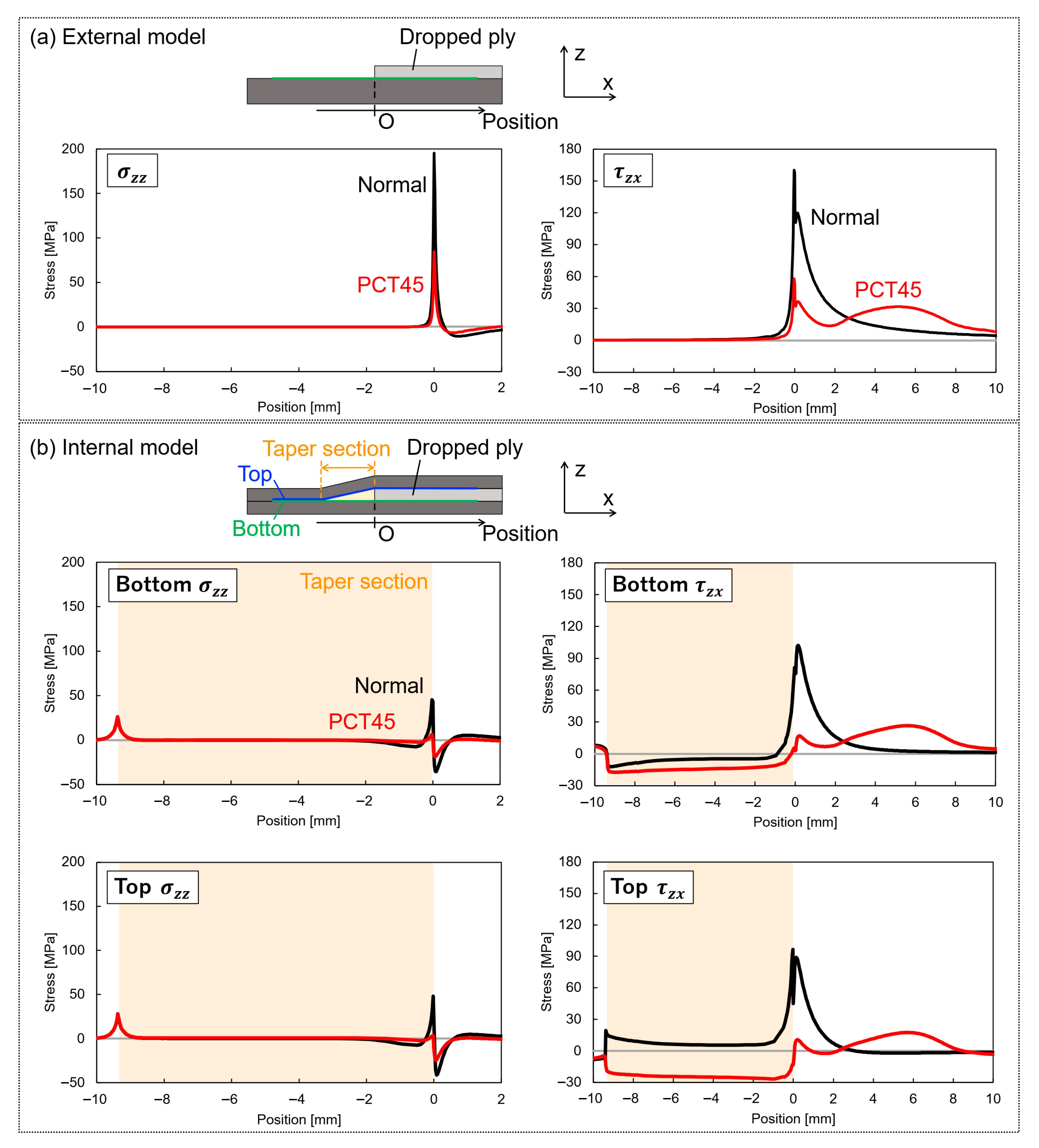
Figure 5 shows the calculated results of σ z z and τ z x along the interface at the specimen center. Note that σ z z is the peel stress and τ z x is the interface shear stress that contributes to the tensile load transfer to the dropped ply.
In the Normal of External model (Figure 5a), both σ z z and τ z x had sharp peaks near the ply drop-off (i.e., Position = 0 mm). In contrast, PCT45 of External model had much lower σ z z and τ z x peaks near the ply drop-off, which is the effect of PCT reducing the longitudinal stiffness at the edge of the dropped ply [26,30]. τ z x of PCT45 had another peak between 3 mm and 8 mm as the fiber angle of the dropped ply gradually changed from 45° to 0°. This was because the gradual increase in the longitudinal tensile stiffness of the dropped ply dispersed the position where the tensile load was transferred from the base laminate to the dropped ply. Because PCT reduces both the out-of-plane stresses σ z z and τ z x , PCT is able to suppress delamination of the external ply drops [26,30].
Similarly to the External case, in Normal of Internal model (Figure 5b), both σ z z and τ z x had sharp peaks near the ply drop-off (i.e., Position = 0 mm). However, compared to External, the peak of σ z z was much lower and the peak of τ z x was slightly lower. This indicates that internal ply drops are more resistant to delamination than external ply drops, and that Mode-II delamination propagation is dominant for the internal ply drop-off. Furthermore, the stress distributions were approximately the same at both the top and bottom interfaces of the dropped ply, indicating that tensile load was transferred from both the base laminate and the cover ply to the dropped ply. In PCT45 of Internal model, as in the External case, both σ z z and τ z x peaks near the ply drop-off were significantly reduced, suggesting that PCT is effective in suppressing delamination in internal ply drops as well.
Based on the results of the finite element analysis described above, it is expected that PCT improves the fatigue properties of internal ply drop-offs. However, as observed in the tensile fatigue tests of external ply drop offs (Figure 2, [30]), the introduction of PCT may change the fatigue failure mode of internal ply drops. Therefore, tensile fatigue testing is conducted in the next section to clarify the fracture behavior of internal ply drops with PCT and compare the effectiveness of PCT in internal ply drop-off and external ply drop-off.

3. Tensile Fatigue Test

3.1. Materials and Methods

3.1.1. Specimen Preparation

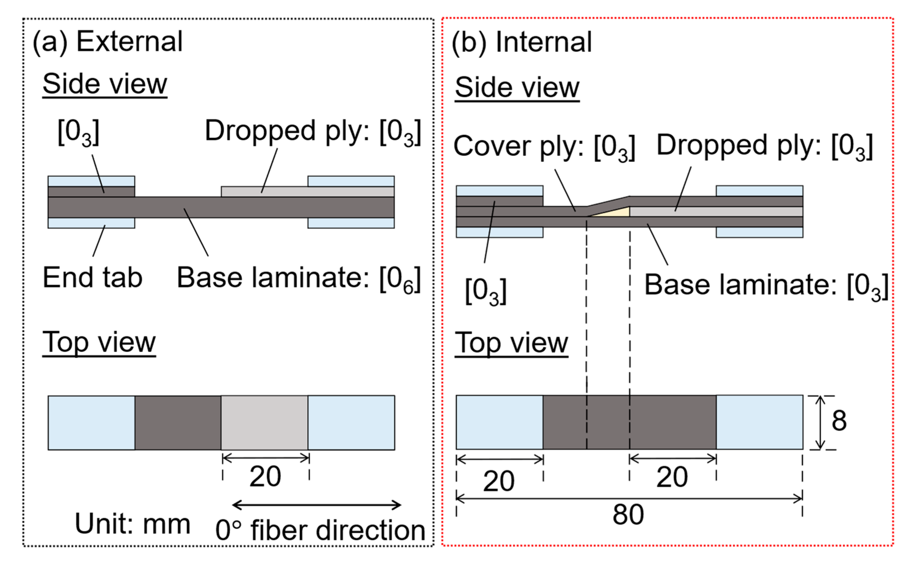
The specimens were fabricated using carbon fiber/epoxy prepreg (T700SC/2592, Toray Industries, Inc.). The specimen geometry is shown in Figure 6. Two types of specimens were prepared: External specimen with external ply drop-off (Figure 6a) and Internal specimen with internal ply drop-off (Figure 6b). The stacking sequence of External specimens was [06] for the base laminate and [03] for the dropped ply. Preliminary tests confirmed that damage did not occur in PCT specimens when the dropped ply was one ply, so the dropped ply was set to three plies to make damage more likely to occur. In the Internal specimen, the base laminate, the dropped ply and the covered ply all had a stacking sequence of [03]. Three plies were dropped simultaneously at one location as in the case of External specimen. So, the External and Internal specimens had comparable load carrying capacity, with the thick section being [09] and the thin section being [06]. Two types of specimens were prepared for each of the External and Internal specimens: Normal specimen with a 0° fiber direction at the end of the dropped ply and PCT45 specimen with 45° PCT angle, 8 mm PCT radius and 8 mm modified zone length (Figure 4). Note that PCT can be introduced into the specimen by shearing the edge of the pre-cured dropped ply prepreg in the in-plane direction with a custom-made sliding mechanism [26,30].
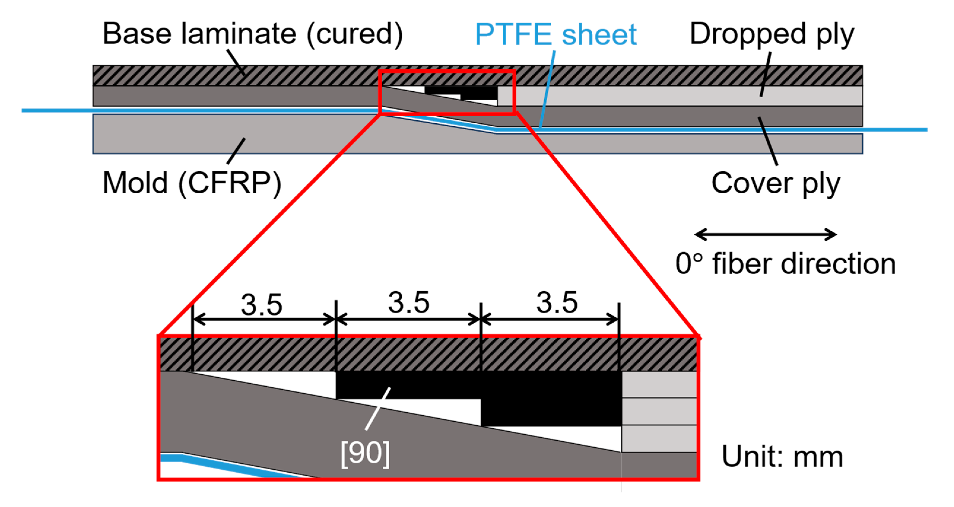
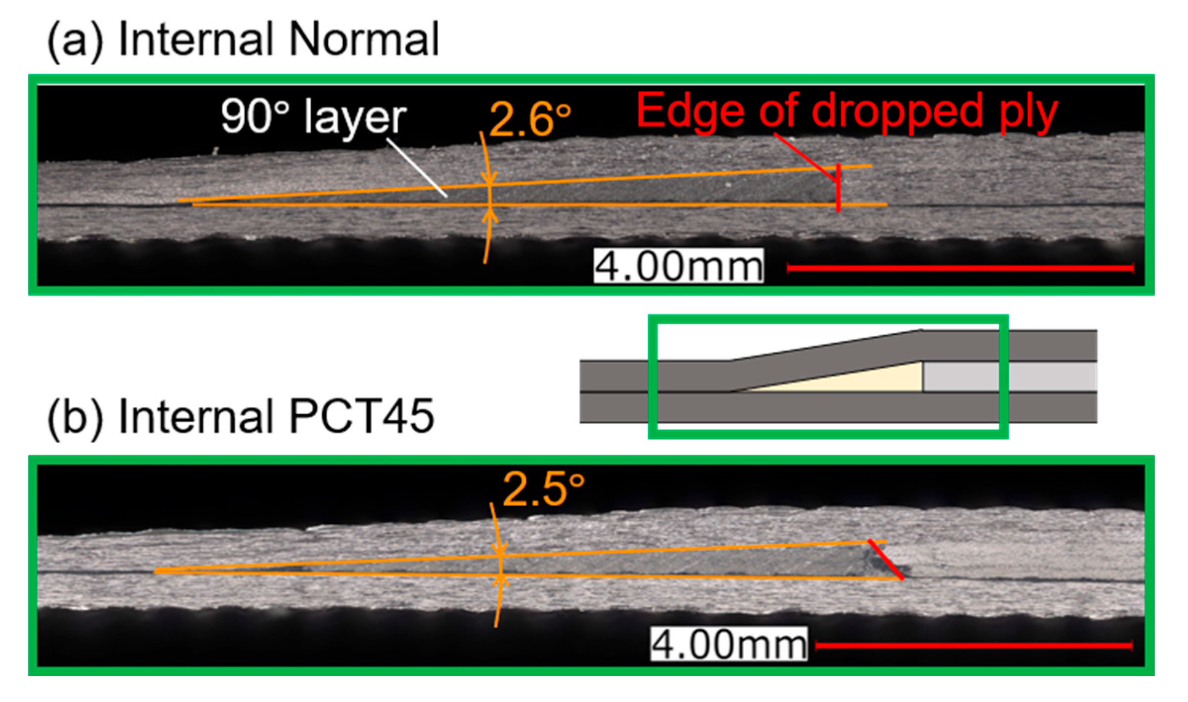
In a preliminary experiment, out-of-plane fiber wrinkles were observed when the dropped ply and base laminate were co-cured. The mechanical properties of the laminate change due to the fiber wrinkles [32], and the magnitude of wrinkles is different whether PCT is introduced or not. To eliminate the effect of fiber wrinkles and evaluate the sole effect of PCT, the base laminate was first cured and then the dropped plies were co-bonded. Specifically, peel plies (Peel Ply PA90, Diatex SAS, Saint Genis Laval, France) were laminated on the surface of stacked base laminate prepreg and the assembly was vacuum-bagged on an aluminum plate. The base laminate was cured in an autoclave (Ashida MFG Co., Ltd., Nara, Japan) under a pressure of 0.3 MPa. The temperature was increased to 130 °C at a rate of 2 °C/min and maintained at 130 °C for 2 h. After curing, the peel plies were removed. The method of co-bonding the dropped ply onto the cured base laminate differed between External and Internal specimens. In the case of External, dropped ply prepreg was laminated on the peeled surface without adhesives. The assembly was then cured using the same curing cycle used for the base laminate. In contrast, in the case of Internal, the cured base laminate and the dropped ply prepreg and the cover ply prepreg were laminated on a mold with a 2.5° taper as shown in Figure 7. It is well known that the taper angle significantly changes the mechanical properties of tapered laminates [6], so the mold was used to accurately control the taper angle. Furthermore, as shown in Figure 7, the 90° prepreg sheets were stacked in a staircase-like manner in the triangle space between the cover ply and the base laminate to prevent the taper from collapsing. The assembly was then cured using the same curing cycle used for the base laminate. Figure 8 shows cross-sectional micrographs of the tapered sections in the Internal specimens after curing. The triangle space between the cover ply and the base laminate was filled with 90° layers and no voids were observed. The taper angle was approximately 2.5°.

3.1.2. Test Method

Tensile fatigue tests were conducted using a hydraulic servo fatigue testing machine (EHF-EB5, Shimadzu Corp., Kyoto, Japan). The stress ratio R was set to 0.1, and the loading frequency was 8.0 Hz. Under these conditions, there was no increase in the specimen temperature. Two loading conditions were used where the maximum tensile stress in the thin section of the specimen was 680 MPa and 1190 MPa. The tensile strain in the thin section was 0.5% at 680 MPa and 0.9% at 1190 MPa. These two conditions were determined based on the finding of the previous research by the authors [30], where the initial damage mode changed from delamination from the ply drop-off to matrix cracking along the curving fibers at a tensile strain of 0.7% (Figure 2).
The fatigue failure process was evaluated by a combination of visual observation and X-ray CT imaging. For delamination propagation assessment, one side of the specimen was coated with thin white paint, and scale marks were drawn at 2 mm intervals. During the test, the damage initiation and delamination propagation on the painted surface were observed with a magnifying glass. Damage initiation from areas other than ply drop-offs is difficult to observe visually during test, and delamination propagation is not always uniform in the width direction. Therefore, the specimen was removed from the fatigue testing machine after a certain fatigue cycle, and X-ray CT imaging (Skyscan1272, Bruker Corp., Billerica, MA, United States) was performed. Before X-ray CT imaging, a contrast agent was applied to the specimen to enhance the visibility of damage.

3.2. Results and Discussions

3.2.1. Low Loading Condition (Maximum Stress 680 MPa, Maximum Strain 0.5%)

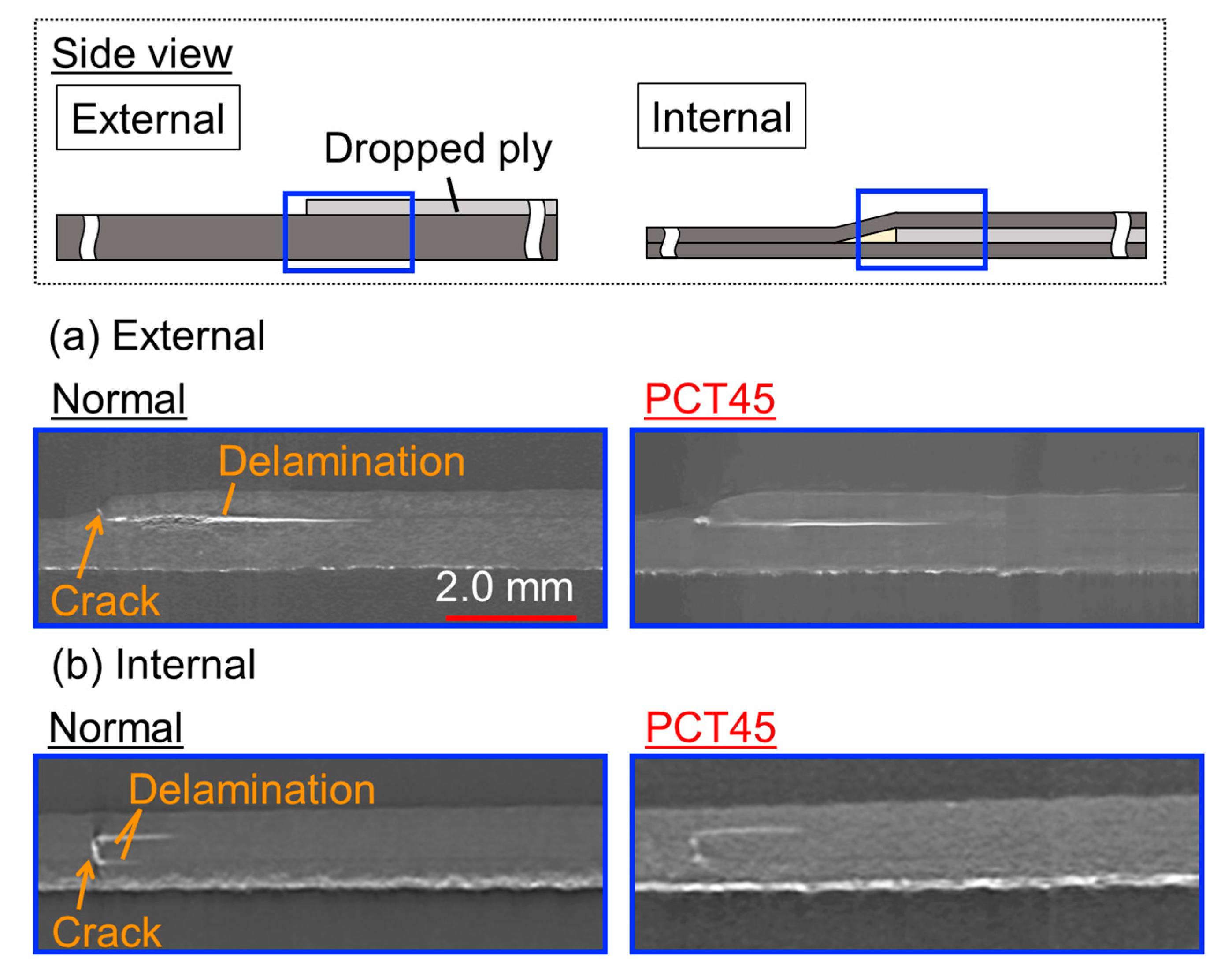
At this load level, the matrix crack at the ply drop-off was the initial damage (Figure 9) and the starting point of delamination for both the External and Internal specimens, regardless of whether PCT was introduced or not. Table 2 shows the number of cycles at which the initial damage occurred. The initial damage was delayed for PCT45 compared to Normal for both Internal and External. This was because the introduction of PCT suppressed the stress concentration at the edge of the dropped ply (Figure 5).
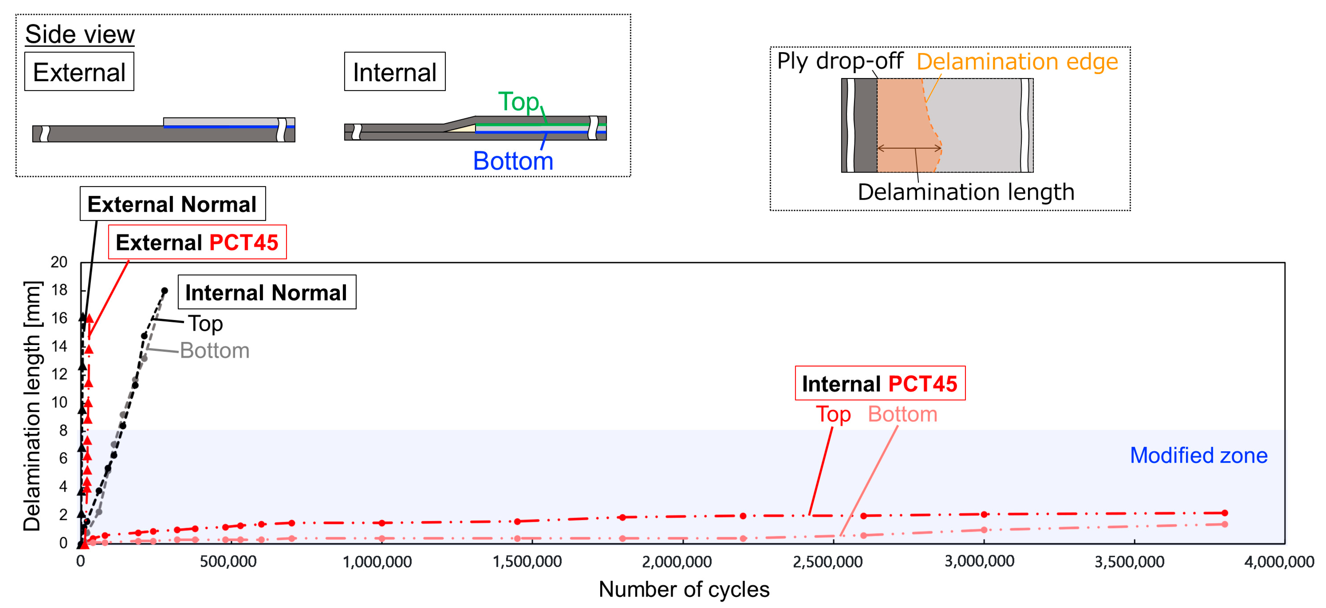
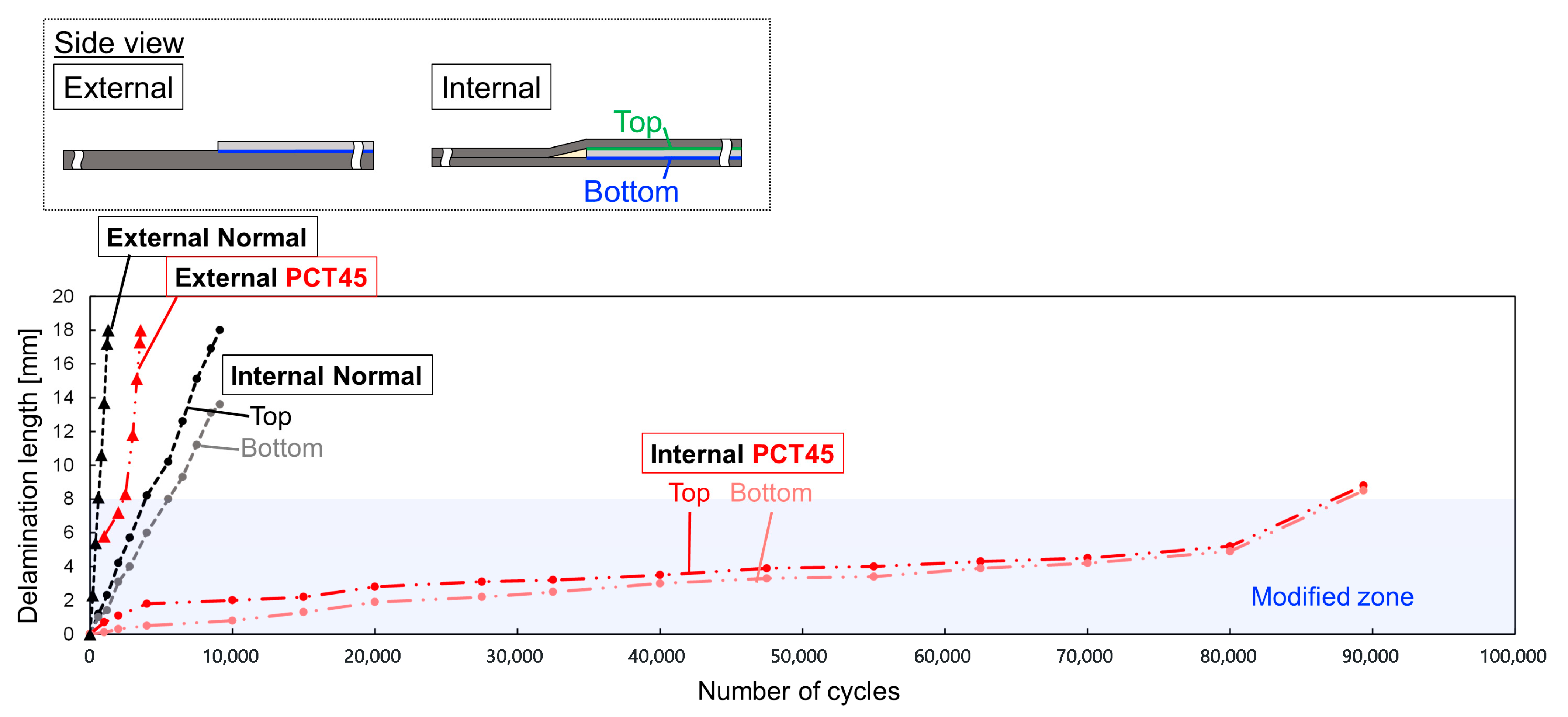
Figure 10 shows the delamination length defined as the distance between the ply drop-off and the point where delamination propagated the most (delamination edge, upper right of Figure 10). Internal specimen has two lines because delamination propagated at both the top and bottom interfaces of the dropped ply. All lines in Figure 10 started with a delamination length of 0 mm because the initial damage was cracking at the ply drop-off. Figure 10 indicates that, overall, the delamination propagation was significantly slower for Internal than for External. In the case of Internal, although delamination propagation was slightly slower at the lower interface, the behavior of delamination propagation at the upper and lower interfaces was similar. The PCT45 had a significantly slower delamination propagation rate for both External and Internal, which was as expected from the results of the finite element analysis in Section 2. Especially, the delamination suppression effect of PCT in Internal was remarkable, and delamination was limited to the area where PCT was introduced (i.e., less than 8 mm) even when PCT45 was loaded with 10 times the number of cycles that delamination reached the edge of the specimen in Normal. This suppression of delamination growth is due to the stress concentration relief effect by PCT. The above results successfully confirmed that PCT is highly effective for internal ply drop-offs under relatively low loading conditions, where delamination starts from the ply drop-off.

3.2.2. High Loading Condition (Maximum Stress 1190 MPa, Maximum Strain 0.9%)

Figure 11 shows the delamination length. In Normal specimens of both External and Internal (Black lines), the initial damage was matrix cracking at the ply drop-off, as in the low loading case (Figure 9). So, the delamination length of Normal in Figure 11 started from 0 mm and increased in proportion to the increase in the number of cycles. In contrast, the failure behavior of PCT45 was different from that under the low loading condition. In the case of External, as in the authors’ previous study [30], cracks occurred along the curved fibers and delamination propagated from the inside of the cracks (Figure 12a). This is the reason why the delamination length of External PCT45 started at 6 mm in Figure 11. Since the delamination occurred from the end of the PCT modified zone, the delamination edge quickly reached the rigid area, where the fiber direction of the dropped ply was 0° and the delamination propagation was fast, limiting the delamination suppression effect of PCT [30]. In the case of Internal PCT45, however, the initial damage was not cracking along the curved fibers. As in the low loading case, ply drop-off cracking was the first to appear, from which delamination developed (Figure 12b). Interestingly, at 10,000 cycles, as in the External case, a crack developed along the curved fibers, but delamination did not propagate from the inside of the crack. Delamination starting from the matrix crack at the ply drop-off propagated slowly and then accelerated as the delamination edge approached the end of the PCT modified zone and the longitudinal stiffness of the dropped ply at the delamination edge increased. Finally splitting of the base laminate occurred and the specimen failed. As a result, in the Internal case, PCT45 failed at 10 times the cycles of Normal, as shown in Figure 11.
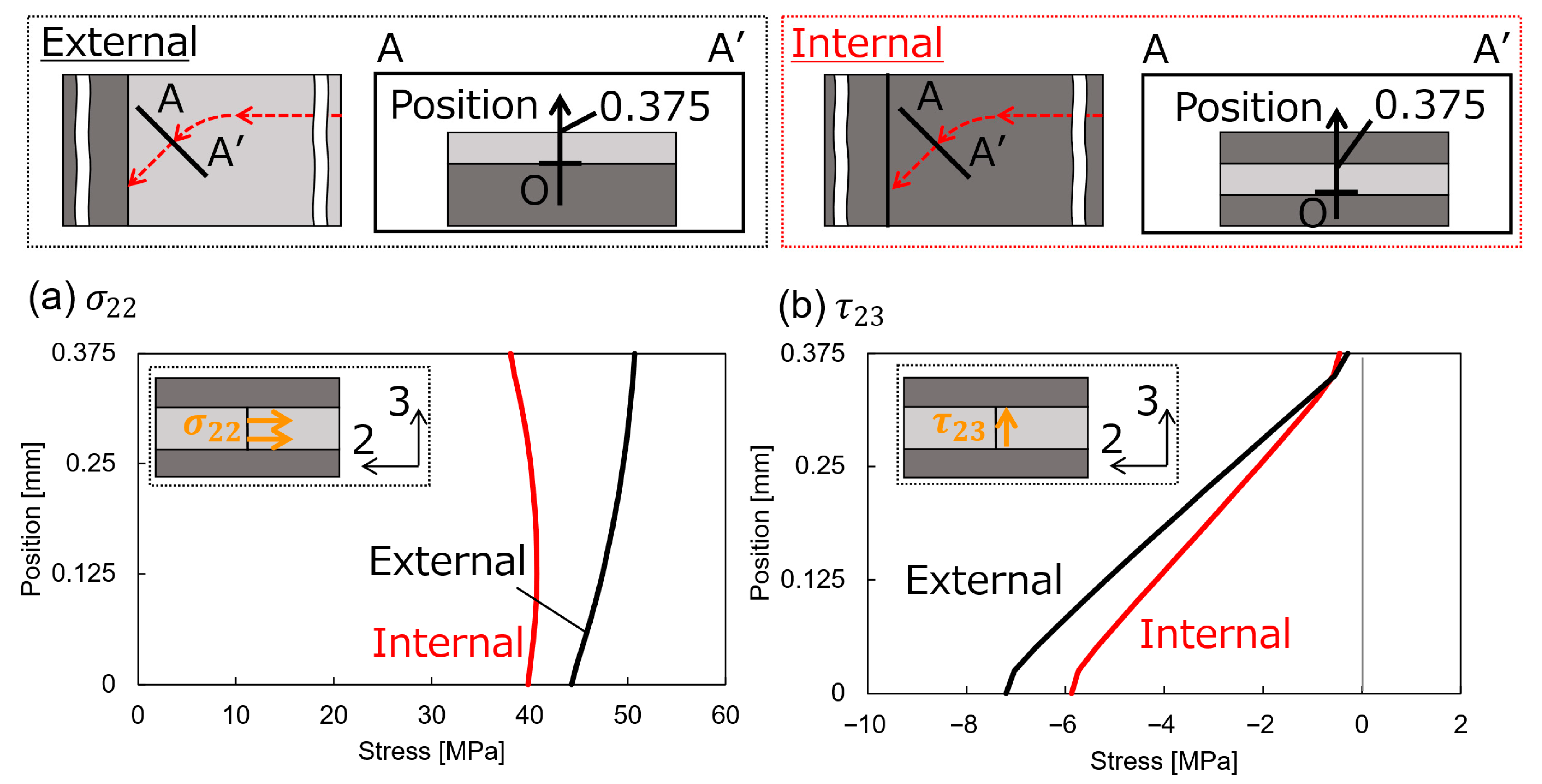
So, the high loading resulted in cracks along the curved fibers for both External PCT 45 and Internal PCT 45, but the delamination did not propagate from the inside of the cracks in Internal PCT45 (Figure 12). To investigate the reason for this, additional finite element analysis was performed using the PCT models in Figure 3. Note that, to simulate the high-loading test conditions, the x-directional displacement was increased so that the stress at the thin section was 1190 MPa. In addition, a seam crack was introduced at the edge of the dropped ply in the Internal model to simulate the ply drop-off cracking (Figure 9). Figure 13 shows the distribution of the transverse stress  σ 2 and the out-of-plane shear stress τ 23 along the thickness direction at the position where the fibers finish curving. At this position, delamination propagation inside the crack was most pronounced in the External case at the early stage (Figure 12a). Note that the stress deformation state after crack initiation is equivalent to the superposition of (a) the state before crack initiation and (b) the state where the stress at the crack initiation position is reversed and applied to the crack surface (Figure 14). In PCT, as shown in Figure 5, as the fiber angle of the dropped ply decreases from 45° and the stiffness in the tensile direction increases, tensile load is transferred from the base laminate to the dropped ply through interfacial shear stress. Due to this shear lag effect, in the case of the External PCT, σ 22 was higher closer to the top surface (Figure 13a) and τ 23 was large (Figure 13b). These stresses act to warp the inside of the crack (Figure 14a), causing delamination to propagate [26]. In contrast, in Internal PCT, σ 22 was maximum at the center of the thickness direction (Figure 13a). This was because the tensile load was transferred from both the top and bottom interfaces of the dropped ply. As a result, the effect of the shear lag was smaller than in the External case, where the tensile load was transferred only from the bottom interface. This also led to the smaller shear stress τ 23 (Figure 13b). Therefore, the stress to open the crack was smaller (Figure 14b), and the delamination did not propagate from the inside of the crack.
These results clearly demonstrate the advantages of internal ply drop-off in applying PCT. In the case of external ply drop-off, the failure occurs early due to the propagation of delamination from inside of the cracks along curving fibers, whereas in the case of internal ply drop-off, the delamination from cracks along curving fibers is suppressed and the failure occurs after slow propagation of delamination from the ply drop-off. This allows the delamination suppression effect of PCT to be fully utilized.

4. Conclusions

Following the authors’ basic study using external ply drop-off without cover plies [30], this study evaluated the fatigue damage suppression characteristic of PCT in internal ply drop-off with cover plies to confirm the effectiveness of PCT in practical composite laminate configurations.
First, finite element analysis was performed to confirm that PCT in internal ply drop-off effectively suppresses out-of-plane stresses at the interface that cause delamination. In subsequent fatigue tests, PCT showed significantly enhanced fatigue damage suppression characteristic at the internal ply drop-off than at the external ply drop-off. In particular, under a high loading condition, the delamination propagation from the inside of the matrix crack along the curved fibers, which significantly reduces the effectiveness of PCT in external ply drop-off [30], was suppressed. Finite element analysis confirmed that the additional stress transfer from the cover ply to the dropped ply suppressed the curved matrix crack opening, which in turn delayed the delamination propagation.
These results demonstrated that the fatigue damage suppression effect of PCT is enhanced in practical composite ply drop-off configurations with cover plies.

Author Contributions

Conceptualization, T.Y. and S.M.; Methodology, T.Y. and S.M.; Validation, T.Y.; Formal analysis, T.Y.; Investigation, T.Y.; Resources, S.M.; Data curation, T.Y. and S.M.; Writing—original draft, T.Y. and S.M.; Writing—review & editing, S.M.; Visualization, T.Y.; Supervision, S.M.; Project administration, S.M. All authors have read and agreed to the published version of the manuscript.

Funding

This research received no external funding.

Data Availability Statement

The raw data supporting the conclusions of this article will be made available by the authors on request.

Conflicts of Interest

The authors declare no conflicts of interest.

References

  1. Murri, G.; Schaff, J. Fatigue life methodology for tapered hybrid composite flexbeams. Compos. Sci. Technol. 2006, 66, 499–508. [Google Scholar] [CrossRef]
  2. Wisnom, M.R.; Dixon, R.; Hill, G. Delamination in asymmetrically tapered composites loaded in tension. Compos. Struct. 1996, 35, 309–322. [Google Scholar] [CrossRef]
  3. Zhang, B.; Kawashita, L.F.; Jones, M.I.; Lander, J.K.; Hallett, S.R. An experimental and numerical investigation into damage mechanisms in tapered laminates under tensile loading. Compos. Part A Appl. Sci. Manuf. 2020, 133, 105862. [Google Scholar] [CrossRef]
  4. Allegri, G.; Wisnom, M.R.; Hallett, S.R. A simplified approach to the damage tolerance design of asymmetric tapered laminates. Part I: Methodology development. Compos. Part A Appl. Sci. Manuf. 2010, 41, 1388–1394. [Google Scholar] [CrossRef]
  5. Wisnom, M.R.; Jones, M.I.; Cui, W. Delamination in composites with terminating internal plies under tension fatigue loading. Compos. Mater. Fatigue Fract. 1995, 5, 486–508. [Google Scholar]
  6. He, K.; Hoa, S.; Ganesan, R. The study of tapered laminated composite structures: A review. Compos. Sci. Technol. 2000, 60, 2643–2657. [Google Scholar] [CrossRef]
  7. Vidyashankar, B.; Murty, A.K. Analysis of laminates with ply drops. Compos. Sci. Technol. 2001, 61, 749–758. [Google Scholar] [CrossRef]
  8. Cui, W.; Wisnom, M.R.; Jones, M. Effect of step spacing on delamination of tapered laminates. Compos. Sci. Technol. 1994, 52, 39–46. [Google Scholar] [CrossRef]
  9. Fikry, M.J.M.; Iizuka, K.; Nakatani, H.; Yoneyama, S.; Vinogradov, V.; Koyanagi, J.; Ogihara, S. Suppression of Delamination in CFRP Laminates with Ply Discontinuity Using Polyamide Mesh. J. Compos. Sci. 2025, 9, 414. [Google Scholar] [CrossRef]
  10. Fikry, M.J.M.; Terashi, N.; Koizumi, K.; Ogihara, S. Inhibition of interlaminar damage in CFRP laminates by inserting non-woven carbon fiber interlaminar reinforced tissue. Adv. Compos. Mater. 2024, 34, 513–533. [Google Scholar] [CrossRef]
  11. Lu, X.; Higuchi, R.; Hua, X.; Nagashima, T.; Yokozeki, T. Experimental and numerical study on failure mechanisms of tapered laminates: Effects of ply thickness and taper ratio. Compos. Sci. Technol. 2024, 256, 110784. [Google Scholar] [CrossRef]
  12. Ohashi, N.; Minakuchi, S. Effect of ply curving termination geometry on fracture behavior and tensile strength of composite ply drop-off. Adv. Compos. Mater. 2025, 1–20. [Google Scholar] [CrossRef]
  13. Obata, S.; Takahashi, K.; Inaba, K. Laminate design for a tapered FRP structure with ply drop-off based on yielding of resin pockets. Compos. Struct. 2020, 253, 112787. [Google Scholar] [CrossRef]
  14. Ergin, F.; Kayran, A. Investigation of Variable Taper Angle Design in Highly Tapered Laminates for Delaying Delamination. Compos. Struct. 2025, 357, 118918. [Google Scholar] [CrossRef]
  15. Fish, J.C.; Vizzini, A.J. Tailoring concepts for improved structural performance of rotorcraft flexbeams. Compos. Eng. 1992, 2, 303–312. [Google Scholar] [CrossRef]
  16. Llanos, A.S.; Vizzini, A.J. The effect of film adhesive on the delamination strength of tapered composites. J. Compos. Mater. 1992, 26, 1968–1983. [Google Scholar] [CrossRef]
  17. Cairns, D.S.; Mandell, J.F.; Scott, M.E.; Maccagnano, J.Z. Design Considerations for Ply Drops in Composite Structures. In Proceedings of the 11th International Conference on Composite Materials, Gold Coast, Australia, 14–18 July 1997. [Google Scholar]
  18. Hua, X.; Higuchi, R.; Yokozeki, T. Enhancement of tensile strength of tapered laminates by utilizing thin-ply composites. Compos. Part B Eng. 2023, 248, 110372. [Google Scholar] [CrossRef]
  19. Helmy, S.; Hoa, S.V. Tensile fatigue behavior of tapered glass fiber reinforced epoxy composites containing nanoclay. Compos. Sci. Technol. 2014, 102, 10–19. [Google Scholar] [CrossRef]
  20. Khan, B.; Potter, K.; Wisnom, M.R. Suppression of delamination at ply drops in tapered composites by ply chamfering. J. Compos. Mater. 2006, 40, 157–174. [Google Scholar] [CrossRef]
  21. Gordon, T.; Xu, X.; Wisnom, M.R.; Kim, B.C. Novel tape termination method for automated fibre placement: Cutting characteristics and delamination suppression. Compos. Part A Appl. Sci. Manuf. 2020, 137, 106023. [Google Scholar] [CrossRef]
  22. Gordon, T.; Xu, X.; Kawashita, L.; Wisnom, M.R.; Hallett, S.R.; Kim, B.C. Delamination suppression in tapered unidirectional laminates with multiple ply drops using a tape scarfing technique. Compos. Part A Appl. Sci. Manuf. 2021, 150, 106627. [Google Scholar] [CrossRef]
  23. Gordon, T.; Xu, X.; Wisnom, M.R.; Hallett, S.R.; Kim, B.C. Improved impact damage resistance of tapered composite laminates using a ply scarfing technique. Compos. Part A Appl. Sci. Manuf. 2023, 166, 107391. [Google Scholar] [CrossRef]
  24. Gordon, T.; Wisnom, M.R.; Kim, B.C. Suppression of compression induced delamination in tapered laminated composites using a ply scarfing method. Compos. Part A Appl. Sci. Manuf. 2024, 176, 107870. [Google Scholar] [CrossRef]
  25. Minakuchi, S.; Takeda, N. Ply Curving Termination: Suppressing Delamination in Tapered Composites. In Proceedings of the 22nd International Conference on Composite Materials, Melbourne, Australia, 11–16 August 2019. [Google Scholar]
  26. Ohashi, N.; Yoshida, T.; Minakuchi, S. Ply curving termination for enhancing tensile strength of composite ply drop-off: Static evaluation and failure mechanism. Adv. Compos. Mater. 2025, 34, 307–328. [Google Scholar] [CrossRef]
  27. Wisnom, M.R.; Jones, M.I.; Cui, W. Failure of tapered composites under static and fatigue tension loading. AIAA J. 1995, 33, 911–918. [Google Scholar] [CrossRef]
  28. Goutianos, S.; Sørensen, B.F. Fatigue crack growth rate at material and geometry transitions in glass-epoxy composites. Compos. Struct. 2021, 275, 114445. [Google Scholar] [CrossRef]
  29. Thawre, M.M.; Verma, K.K.; Jagannathan, N.; Peshwe, D.R.; Paretkar, R.K.; Manjunatha, C.M. Effect of ply-drop on fatigue life of a carbon fiber composite under a fighter aircraft spectrum load sequence. Compos. Part B Eng. 2016, 86, 120–125. [Google Scholar] [CrossRef]
  30. Yoshida, T.; Minakuchi, S. Improving fatigue characteristics of ply drop-off in composite laminate with ply curving termination. Adv. Compos. Mater. 2024, 33, 1209–1223. [Google Scholar] [CrossRef]
  31. Hisada, S.; Minakuchi, S.; Takeda, N. Damage tolerance improvement of composite T-joint under pull-up conditions using an interlocking-fiber-based crack arrester. Compos. Struct. 2020, 253, 112792. [Google Scholar] [CrossRef]
  32. Varkonyi, B.; Belnoue, J.P.H.; Kratz, J.; Hallett, S.R. Predicting consolidation-induced wrinkles and their effects on composites structural performance. Int. J. Mater. Form. 2020, 13, 907–921. [Google Scholar] [CrossRef]
Figure 1. Side view of typical tapered laminates: (a) external ply drop-off; (b) internal ply drop-off.
Jcs 09 00523 g001
Figure 3. Finite element model. (a) External model. (b) Internal model.
Jcs 09 00523 g003
Figure 4. PCT geometry parameters.
Jcs 09 00523 g004
Figure 5. Interface stress calculated using finite element analysis.
Jcs 09 00523 g005
Figure 6. The geometry of specimens used for the tensile fatigue test. (a) External. (b) Internal.
Jcs 09 00523 g006
Figure 7. Specimen and mold setup used for co-bonding process to prepare Internal specimen.
Jcs 09 00523 g007
Figure 8. Cross-sectional micrographs of tapered sections in Internal specimens. (a) Internal Normal. (b) Internal PCT45.
Jcs 09 00523 g008
Figure 9. X-ray CT images of initial damage under low loading condition. (a) External. (b) Internal.
Jcs 09 00523 g009
Figure 10. Delamination length under low loading condition.
Jcs 09 00523 g010
Figure 11. Delamination length under high loading condition.
Jcs 09 00523 g011
Figure 12. X-ray CT images of damage observed in PCT45 under high loading condition. (a) External PCT45. (b) Internal PCT45.
Jcs 09 00523 g012
Figure 13. Stress distribution along thickness direction at position where fibers finish curving. (a) σ 22 . (b) τ 23 . By reversing this stress and applying it to the crack face, the stress deformation state after crack initiation can be explained (Figure 14).
Jcs 09 00523 g013
Figure 14. The principle of superposition used to explain stress deformation state after crack initiation. The stress deformation state after crack initiation (left) is equivalent to the superposition of the state before crack initiation (middle) and the state where the stress at the crack initiation position (Figure 13) is reversed and applied to the crack surface (right). In the case of (a) External (upper), σ 22 , which has high value near the upper surface (Figure 13a), and τ 23 , which has large value overall (Figure 13b), warp the inside of the crack (A’ side), causing delamination to propagate [26]. In contrast, in the case of (b) Internal (lower), additional stress transfer from the cover ply to the dropped ply balances σ 22 in the thickness direction (Figure 13a), and reduces  τ 23 (Figure 13b), preventing delamination from propagating.
Jcs 09 00523 g014
Table 1. Material property of T700SC/2592 [31].
Elastic Moduli [GPa]Poisson’s Ratio
E11E22 = E33G12 = G13G23 ν 12 = ν 13 ν 23
1358.54.82.70.340.49
Table 2. The number of cycles at which initial damage (matrix crack at ply drop-off) occurred.
External NormalExternal PCT45Internal NormalInternal PCT45
Initial damage cycles20024001005000
Disclaimer/Publisher’s Note: The statements, opinions and data contained in all publications are solely those of the individual author(s) and contributor(s) and not of MDPI and/or the editor(s). MDPI and/or the editor(s) disclaim responsibility for any injury to people or property resulting from any ideas, methods, instructions or products referred to in the content.