Abstract
Timber–concrete composite (TCC) systems present a viable alternative to conventional timber or reinforced concrete systems. TCC leverages the advantages of both materials, resulting in an enhanced composite structure. Historically, traditional mechanical connectors such as nails, bolts, and dowels have been used in TCC systems to join timber and concrete components. However, these connectors often fall short in providing sufficient load transfer efficiency. Therefore, the use of screws and, more recently, inclined screws in TCC systems has increased due to their enhanced load transfer efficiency and greater stiffness compared to traditional connections. This review paper consolidates findings from contemporary experimental studies and analytical models, examining the influence of factors such as screw type and inclination angle on the performance of TCC systems for both connection and beam specimens in ultimate and serviceability limit states. Key issues addressed include the shear strength, stiffness, and long-term behaviour of the connection type. By offering a comprehensive synthesis of existing knowledge, this paper aims to inform design practices and contribute to the development of more resilient and efficient TCC systems, supporting their increased adoption in sustainable construction.
1. Introduction
Timber–concrete composite systems (hereafter referred to as TCC) are typically one-way slab or beam elements that combine timber and concrete through a connection. TCC leverages the advantages of both materials, resulting in an enhanced composite structure with concrete part primarily in compression and timber part in tension. TCC structures were introduced in the U.S. for bridge construction in the early 20th century, with increased use after WWII due to steel shortages [1,2]. Since the early 1990s, TCC floor systems have been used in numerous mass timber structures worldwide [3], both in new construction projects and for the refurbishment of existing timber structures, especially older buildings in Europe [4]. TCC systems reduce dead load, lowering seismic and foundation demands [5,6]. Additionally, this system enhances acoustic performance while eliminating the need for separate formwork by casting concrete over timber panels such as cross-laminated timber (CLT) [7,8].
The main purpose of connections in composite systems is to transfer the shear forces between materials while minimizing slip. Various connection types have been used in TCC systems, including connections with mechanical fasteners, notched connections, combined notch–dowel connections and glued connections [5]. Based on their installation, connectors can be categorized as discrete/continuous or vertical/inclined. Mechanical fasteners positioned discretely along the length of a beam or slab create a partially composite system with a non-linear relationship between shear force and relative slip [5,9]. Conversely, glued connections typically form a stiff, almost fully composite system with essentially a linear–elastic response until brittle failure [10]. Over the past five decades, nails, bolts, and dowels have been widely used as mechanical fasteners. However, in recent years, experimental studies have increasingly focused on self-tapping screws, as they offer quick installation and improved mechanical behaviour [11,12]. Additionally, research has shown that the orientation of mechanical fasteners considerably influences connection strength and stiffness [13,14].
Currently, few design standards address the design of TCC systems; some examples are part 2 of Eurocode 5 (EC5)- Design of Timber Structures [15], the Canadian Highway Bridge Design Code (CSA S6) [16] for TCC bridge deck design, and the recently published 2024 edition of the Canadian Timber Design Standard (CSA O86) [17]. As with any structural system, TCC system design must meet both Serviceability Limit States (SLS) and Ultimate Limit States (ULS). ULS design focusses on system strength, while SLS primarily addresses deflection in the short- and long-term as well as vibration [9]; however, available studies have shown that, due to the rheological characteristics of timber, concrete, and the connection between them, TCC design is usually governed by SLS requirements, which must be thoroughly checked to ensure acceptable performance under service conditions [18,19,20]. Yeoh et al. [3] proposed that TCC design must consider two major considerations: (1) partial composite action arising from the flexibility of shear connectors and (2) time-dependent properties of the component materials.
This article reviews publications that focus on TCC systems connected by inclined self-tapping screws. It begins by summarizing and comparing short-term experimental works and the analytical models proposed for the prediction of the mechanical behaviour of inclined screws in TCC systems. The article then explores long-term experiments conducted on inclined screws in TCC systems and compares the influences of key determinants, such as screw angle, component properties, and environmental conditions, on their long-term performance along with the prediction models. This study only focuses on static loading to isolate key factors influencing the short- and long-term behaviour of inclined self-tapping screws. Dynamic loading, while relevant, introduces complexities like mass, damping, and resonance effects, which were beyond this study’s scope.
2. Short-Term Performance of Inclined Screws in TCC Systems
2.1. Short-Term Experimental Work
Empirical examinations of TCC systems are usually conducted on their connections or assembly (beam or slabs). These tests are designed to evaluate the strength, stiffness, and failure modes of the system. TCC beams are typically tested using a four-point bending test method, while the mechanical behaviour of the connections is commonly evaluated through a shear (push-out) test. This testing approach has been used to investigate connections in composite systems such as TCC as well as in other systems such as steel–concrete composite beams, since the 1950s [21,22]. From the literature, no standardized tests for TCC connection are available. Consequently, researchers have adopted principles outlined in EN 26891 [23] initially developed for timber-to-timber connections with mechanical fasteners [9,19]. CSA O86 [17] also recommends the testing protocols from EN 26891 [23] and ASTM D6815 [24] for TCC connections that have at least two mechanical fasteners in each shear plane. The outcome of a connection test is load-slip curve, and the key mechanical properties are load-carrying capacity (strength), slip modulus (stiffness), and ultimate deformation capacity or ductility [14]. Figure 1 illustrates various methods for conducting connection tests in TCC systems with mechanical fasteners. Connection test specimens can be categorized as three-layer (double-shear) or two-layer tests [7]. Reinforcement is often added to the concrete, mainly for shrinkage and temperature crack control [25]. Additionally, an interlayer is sometimes placed between the timber and concrete to reduce sound transmission between adjacent units. This interlayer can be wood, polyethylene (PE) or foam, and usually has a thickness of 5 to 30 mm [1,26].
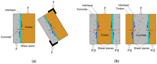
Figure 1.
Connection test specimens: (a) two-member test method; (b) three-member test method, left: concrete–timber–concrete, right: timber–concrete–timber.
Analysis of the connection test results revealed that the fastener insertion angle to the shear plane can play a critical role in mechanical behaviour. Khorsandnia et al. [13] reported that using screws at a 45° angle in a crossed-pair arrangement, compared to 90° screws, increased connection stiffness by about 66%. Appavuravther et al. [27] also noted that varying the angle from 90° to 45° led to a substantial increase in stiffness, surpassing 100%. The results demonstrated the combined effect of withdrawal and bearing resistance in inclined screws, which enhances load distribution within the connection. This improved force distribution increases both stiffness and strength, ultimately boosting the composite action of the system. Additionally, Kenel and Meierhofer [28] showed that when the screw angle exceeds 45°, the connection stiffness decreases by approximately 10% for every additional 5° beyond this threshold.
Inclined screws can be used as single units or in cross pairs. Studies showed that optimal performance is achieved when they are arranged in a crossed-pair orientation [14,28,29]. In this configuration, one screw is subjected to tension and the other to compression under the applied lateral load, creating a truss-like system that maintains the stability of the fasteners and connecting members, Figure 2. According to Marchi et al. [11], coupling two screws with the same inclination and orientation relative to the shear load is the most straightforward method to double the load-bearing capacity per connection point. Also, the two main types of screws investigated in the literature were fully threaded and partially threaded, as illustrated in Figure 2.
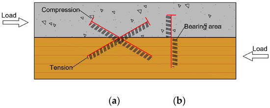
Figure 2.
Screw connection in TCC systems: (a) cross pair; (b) perpendicular to the shear plane.
Understanding the behaviour of a composite system requires insight into the strength and stiffness of the connections between its components. Table 1 summarizes the existing literature on connection test results for inclined screws. In this table, the effects of screw size, insertion angle, material properties for concrete and timber, and insulation layer on connection strength and stiffness are compared. NWAC and LWAC are normal-weight aggregate concrete and lightweight aggregate concrete, respectively. Laminated Veneer Lumber (LVL), Glued Laminated Lumber (GLT), and Laminated Strand Lumber (LSL) were used in the experiments. It is worth mentioning that variations in connection test methods were noted according to Figure 1; for instance, Khorsandnia et al. [13] tested fully confined specimens, which, as reported, may slightly overestimate strength and stiffness due to horizontal reaction forces that limit rotation [1,30]. The ± symbol in this table represents crossed pairs of screws, and the strength and stiffness results for this configuration are for one pair of screws. Also, the study conducted by Fragiacomo [31] involved an upgrade technique for converting a residential floor to an office in the UK, and LWAC was used since the overall weight of the concrete layer could be a concern.

Table 1.
Summary of experimental research on TCC connections with inclined self-tapping screws.
In most cases, the use of crossed-pair screws has been shown to enhance both strength and stiffness, particularly in connection with fully threaded screws. A comparison of screw inclination angles showed that 30° inclined screws were 38% stiffer and 12% stronger than 45° screws [14]. Similarly, Tannert et al. [35] observed that shifting from a 45° to a 30° configuration nearly doubled the connection’s strength and stiffness. This increased strength and stiffness can be attributed to the more efficient load transfer mechanism at the lower angle. The 30° angle allows for a greater contribution of withdrawal resistance than bearing resistance because withdrawal resistance generally plays a bigger role in resisting lateral load in connections with inclined screws. Also, as expected, increasing the screw size increased the strength and stiffness of connections because larger screws offer greater withdrawal and shear resistance [11,27].
In general, changing from NWAC to LWAC did not significantly affect the strength and stiffness of the inclined connections, even in cases where the concrete had lower compressive strength; however, it was suggested that it could alter the failure mode when the concrete has a lower modulus of elasticity [26,27]. This observation shows that the properties of timber and fasteners are a more dominant component than concrete properties [36]. In the study by Jorge et al. [26], changing NWAC to LWAC with similar concrete compressive strengths reduced the mean connection strength by 30–50%, which can be attributed to aggregate quality and strength or the bonding between aggregates with cement paste in this test. No significant influence on the mechanical properties of inclined screw connections was observed based on the types of wood used [14,35].
The presence of an interlayer between timber and concrete has been shown to decrease both the strength and stiffness of the connection, with a more pronounced effect on the stiffness [1,26]. The decrease can depend on the interlayer thickness and on material that can affect the bonding between each of the components and the interlayer. Mirdad and Chui [14] observed that changing the insulation layer thickness from 5 to 15 mm caused a connection strength decrease of 5 to 22% and around 50% for stiffness, and the influence was more pronounced compared to changing the screw insertion angle. Substantial reductions in stiffness and strength were also observed in timber-to-timber connections with inclined screws, as noted by De Santis et al. [12]. Also, some studies have shown that the influence of the interlayer also depends on its mechanical properties. For example, granite chips bonded to timber with epoxy glue have been shown to enhance both strength and stiffness in TCC members by improving load transfer and reducing slip at the interface [37,38]. While conventional interlayers often degrade performance, tailored solutions can improve it, highlighting the importance of interlayer material selection in TCC design.
Failure in TCC systems with mechanical fasteners typically happens due to the formation of plastic hinges in the fasteners or timber failure which may be accompanied by cracks or minor crushing in concrete at the interface [1,20]. He et al. [39] showed that by increasing the screw size, the failure mode can change from plastic hinge forming to concrete cracking, which can be attributed to higher stresses being transferred to the concrete. Sebastian et al. [40] also investigated TCC beams with inclined screws under negative bending and observed that in concrete tension zones, the connections showed more ductility. For screws inserted normal to the shear plane, the most common failure mode was due to the failure of concrete and plastic hinges forming in the screws [27].
In addition to connection tests, bending tests have also been performed on TCC systems with inclined screws. For screws, van der Linden [1] noted that the gap between the interlayer and the timber was caused by screw pull-out, starting with those near the beam ends under high shear forces. As these screws disengaged, the load was re-distributed to the other connectors until they reached capacity, causing the gap to spread towards mid-span while widening at the ends. For the same connection type, Jorge et al. [26] observed that beam failure occurred primarily in the timber element in a brittle manner, which is expected under bending. Despite this, the composite beam demonstrated significant deformability, indicative of ductile behaviour, while cracking in the concrete was not readily apparent. This indicates that fastener yielding likely occurred before ultimate failure in the timber. Figure 3 shows some of the common failure modes in TCC systems with screw and notched connections.
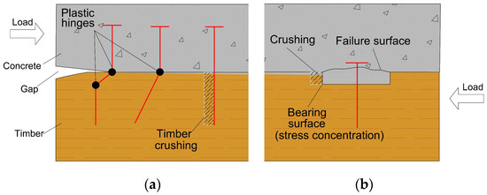
Figure 3.
Common failure modes in TCC systems: (a) screw connections; (b) notched connections.
2.2. Analytical Models of Strength and Stiffness
Various analytical models have been developed to predict the strength, stiffness, and failure modes of TCC systems with inclined screws which offer valuable insights into the mechanical performance of these connections. In the case of timber-to-timber connections, analytical models were introduced by Bejtka and Blaß [41] and Tomasi et al. [42]. De Santis et al. [12] also proposed an empirical model for insulated inclined screws in timber-to-timber connections that could describe the experimental load–slip curves. In this section, prominent models proposed in the literature and their effectiveness in simulating the performance of TCC systems are discussed.
The models used for calculating the strength of TCC connections generally come from the Johansen or European Yield Theory for timber-to-timber or timber-to-steel connections [43], as no specific model for the strength of TCC connections has been introduced. The primary approaches adopted for the strength models generally assume that concrete behaves as a completely rigid component while also considering different failure modes in both the timber and the fasteners [10,44]. Kavaliauskas et al. [45] extended Johansen’s Yield Model, considering failure modes in wood and screws while assuming the screw in concrete to be rigid. Although the model aligned with experimental results, the failure modes differed, likely due to limited fastener ductility and the influence of screw inclination on timber strength. In the case of using LWAC with a smaller modulus of elasticity, Appavuravther et al. [27] recommended considering concrete failure as well.
The Johansen Yield Theory is applicable only to screws oriented perpendicular to the shear plane and does not account for critical factors such as screw withdrawal strength, the angle between the screw axis and the applied force, and the friction between timber elements at the shear plane interface [42]. Therefore, the models based on Johansen’s Theory were extended to address these conditions for inclined screws. Marchi et al. [11] proposed analytical models for the strength and stiffness of single and crossed-pair screws based on the modification of the Johansen Yield Model and the model proposed by Kavaliauskas et al. [45] which also included failure in the concrete part. Their results indicated that the friction force between timber and concrete should be considered in analytical models. Other analytical models have been developed by extending the theory in earlier models to calculate the strength and stiffness of TCC connections with inclined screws and an insulation layer [33,46,47]. Mirdad and Chui [47] proposed two analytical models of inclined screws in solid and layered timber by characterizing all possible kinematical failure modes. Experimental validation with various material properties showed that the models predicted the mode of failure and strength within 10% of the experimental results. These models consider both bearing and withdrawal actions of the screws, incorporating corrections for embedment stiffness and friction between the concrete and mass timber panel. For the stiffness of inclined screws in TCC connections, Symons et al. [48] introduced an analytical model using the ‘Winkler’ or beam-on-elastic-foundation approach and modeling timber as orthogonal springs with varying stiffness. The results showed reasonable agreement with experimental data, with an overestimation of about 20%, likely due to the assumption of a fully rigid screw in concrete.
EN 26891 [23] recommends distinct equations for the serviceability and ultimate part of the load–slip curves to address the actual non-linear behaviour of the connection. Based on this test protocol, four different connection stiffness properties are defined: initial stiffness (), SLS stiffness () for two loading paths, and ULS stiffness (). EC5- Design of Timber structures- Part 1-1 [49] in its latest draft proposes Equations (1) and (2) for calculating the serviceability stiffness of laterally loaded and axially loaded mechanical fasteners in timber-to-timber connections, respectively. Also, EC5 recommends considering a fraction of the connection stiffness in the ultimate limit state due to its nonlinear behaviour, as indicated in Equation (3). The connection reduction in stiffness is likely due to plastic behaviour in timber and screw above service load levels [32].
To consider the combined effect of laterally and axially loaded conditions in inclined screws without any gap between the members, EC5 [49] recommends that the effective slip modulus be calculated according to Equation (4) for inclined screws in tension and Equation (5) for inclined screws in cross-pair.
3. Long-Term Performance of TCC Connections and Systems with Inclined Screws
3.1. Experimental Work
As stated, TCC systems must be evaluated for both ULS and SLS design requirements. It is known that SLS requirements, such as vibration or long-term deformations, typically govern the design of TCC systems [9,18,19,20]. The main factors that influence these long-term deformations are sustained loading, concrete shrinkage, and changes in environmental conditions. Concrete exhibits viscoelastic creep under sustained loading and the linear shrinkage coefficient of concrete typically ranging from 400 × 10−6 to 900 × 10−6 mm/mm [50]. Timber also experiences viscoelastic creep under sustained load, shrinkage/swelling, and mechano-sorptive creep. Mechano-sorptive creep, in contrast to viscoelastic creep, is a strain increase caused by the combination effect of sustained loading and moisture content changes and is not directly dependent on time. According to Van de Kuilen [51], moisture content variations as small as 1% are enough to trigger mechano-sorptive deformation.
TCC systems are internally statically indeterminate; thus, deformations in one material or component cannot occur independently without inducing stresses in other components. This leads to stress redistribution and gradual increases in deflection over time [8,9,19,52,53,54,55]. Therefore, TCCs are complex systems, and their deflection is expected to gradually increase due to the creep and shrinkage that occur over time in its components [19,20,56,57]. Thus, in addition to the short-term tests, long-term tests have also been conducted on TCC systems with inclined screws, generally to establish the creep coefficient of the system (global creep coefficient) and the connection. The creep coefficient, , for the connection is generally defined as the ratio of slip at a time of interest relative to the instantaneous slip, Equation (6):
where is the relative slip between timber and concrete, and and are the time of interest and instantaneous time, respectively. The instantaneous time, , used for determining instantaneous slip, , is recommended to be 10 min after load application [10,26,51]. ASTM D6815 [24] considers this time as 1 min after the load application. For the long-term testing of beams, measurements are typically focused on midspan deflection, which will result in the global creep coefficient of the system. According to Equation (6), a larger instantaneous displacement leads to a smaller creep coefficient.
In the long-term TCC connection test, the sustained shear load is often set at 30% of the connection strength, reflecting typical service load levels. For TCC beams, the long-term load is usually between 12 and 15% of the bending strength, excluding the self-weight of the TCC beams, and between 15 and 20% of the bending strength, when the self-weight is included. Considering the components separately, wood and concrete can be considered to behave linear-elastically when the applied stress is below about 40% of their strengths [58,59,60,61].
In long-term creep experiments, various methods have been used to apply the sustained load. For connection tests, the most common method utilizes a lever system to amplify the load applied to samples, which allows for simultaneous loading of multiple test specimens in a series, Figure 4a [8,25,62]. Linear variable differential transformers (LVDT) or dial gauges are usually used to measure the relative slip between timber and concrete. Long-term testing of TCC beams is usually conducted using the same test setup as short-term bending tests, often using a four-point bending method with loads applied at one-third points of the span. Also, in some studies, a uniformly distributed load (UDL) was applied as the long-term load. In most long-term tests, the tests concluded when no significant changes in creep coefficient or mid-span deflection were detected [8,63].
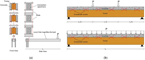
Figure 4.
Common long-term test apparatus: (a) column and lever system for connection long-term testing; (b) TCC beam under 4-point bending test (up) and UDL (down).
By comparing the results of TCC systems with different connection types, it was observed that in some studies, larger long-term deflections were obtained for stiffer connection types, such as glued and notched connections based on their geometry [54,64]. Stiff connection types restrict relative movement between the layers and can create stress concentrations and residual stresses. When TCC systems with rigid connections experienced environmental changes, the increase in internal stress was more pronounced. Therefore, while different connection types may influence deflection outcomes, current design codes and standards, such as EC5 [49] and CSA O86 [17], consider a creep coefficient that is twice that of timber, regardless of the type of connection used. However, based on the literature, values of creep coefficient varied depending on the connection types.
Table 2 and Table 3 summarize the long-term connection and beam tests conducted on TCC systems with inclined screws. In these tables, the key parameters for comparison include environmental conditions (constant or variable), fastener diameter and insertion angle, timber and concrete material type and strength classes, beam span, and connector spacing. Long-term testing of TCC systems is typically conducted under variable environmental conditions to investigate rheological phenomena, such as mechano-sorptive creep and concrete shrinkage. Variable environmental conditions are characterized by significant temperature changes and fluctuations in relative humidity, which lead to moisture absorption or desorption, primarily affecting the timber. These environmental conditions are usually referred to as dry/wet according to CSA O86 [17] or Service Class 1 to 3 based on EC5 [49].
Table 2.
Comparison of creep coefficients for TCC connections with inclined screw.
Table 3.
Comparison of mid-span deflection for TCC systems with inclined screws.
Under constant environmental conditions, Kenel and Meierhofer [28] observed that ±45° screw orientations exhibited less slip over time compared to a connection system with a combination of 90° and ±45° screws, which behaved similarly to their short-term performance. On the other hand, a varying environment was observed to influence the TCC system (global) creep coefficient and mid-span deflection of TCC systems, especially in situations where relative humidity and moisture content changes caused mechano-sorptive creep. Kanócz and Bajzecerová [65] found that mechano-sorptive creep increased total deflection by 30%, with the environmental conditions having a more pronounced effect on the ±45° connection compared to the notched connection. When testing TCC beams with wet wood, Kenel and Meierhofer [28] found that the 1-year mid-span deflection had three times the instantaneous deflection. For 90° screws, it was found that the connection creep coefficient under variable environmental conditions was almost double that of systems under constant environmental conditions [19,62].
The tables do not show a significant effect of the screw size on the creep coefficient, as the screws were nearly uniform in size. However, it can be expected that larger diameters can reduce the creep coefficient as studies on different diameters of dowels have shown [62,67]. This can be related to the greater stiffness of the larger fastener which can distribute loads more effectively. Enhanced load transfer reduces localized stress concentrations, which can help mitigate creep deformation over time.
Based on test results, replacing NWAC with LWAC did not significantly change the creep coefficient of the connections, which is attributed to the dominance of timber and connector type in long-term TCC behaviour [8,25]. Jorge et al. [8] also showed that using LWAC with different compression strengths did not influence the creep coefficient. While LWAC reduces the dead load of TCC systems, it exhibits greater shrinkage strain than NWAC, potentially increasing deflections from shrinkage and decreasing concrete stiffness [8,25]. However, replacing low-shrinkage concrete with NWAC reduced the long-term deflection by approximately 14% [53], which shows the effect of concrete shrinkage on long-term deflections.
In terms of the effect of timber type on the long-term performance of TCC systems with inclined screws, there is insufficient information available to draw definitive conclusions. However, in testing TCC systems connected with dowels, Van de Kuilen and Dias [62] observed that while the timber grades varied across the tests, both solid timber and glued laminated timber exhibited similar creep behaviour. This may suggest that the type of timber (solid or laminated) may have a limited influence on creep performance in these systems, though further investigation is needed to confirm whether this finding extends to TCC systems with inclined screws and under varying environmental conditions.
As an overall conclusion, for the mechanical fasteners considered in tests reported in Table 2, a creep coefficient of less than one can be expected for inclined screws, depending on their properties.
3.2. Prediction Models for the Long-Term Behaviour of TCC Systems and Connections
The first series of TCC analytical models was based on the composite beam theory proposed by Newmark et al. [21] for concrete-steel connections and Möhler [68] for composite structures. For the long-term behaviour of TCC systems, various approaches have been used to predict creep response, with a focus on determining the 50-year creep coefficient (system and connection) or midspan deflection. These models usually incorporate rheological models of timber, concrete, and the connection system separately.
Toratti [69], Hanhijarvi [70], Becker [71], and Martensson [72] all developed rheological models for the long-term behaviour of timber. For concrete, widely used models include those from ACI 209.2R-08 [73] and CEB [74]. Natterer and Hoeft [75] and Ceccotti [76] used an effective elastic modulus method to address the time-dependent characteristics of each component in TCC systems under sustained load. This method has been widely used by researchers over the years, often with some modifications. Other methods are finite element models with one-dimensional frame [56,77,78] or analytical models that are based on provisions from existing codes and standards and have been validated with experimental results and are easy to use for design purposes [18,54,57,66,79,80,81]. However, existing codes and standards, such as CSA O86 [17] and EC5 [49], do not differentiate between connection types and instead associate the creep coefficient of connections with that of timber. This approach may not provide accurate approximation of the long-term behaviour of TCC systems, and thus, more precise methods may be required. Further details about these models can be found in the aforementioned references.
Another common method involves fitting mathematical functions to experimental curves. These functions include equations that can model the creep behaviour of materials such as power-type (Equation (7)) and logarithmic forms (Equation (8)). Also, in the case of viscoelastic materials such as concrete or wood, rheological (mechanical) models such as the generalized Kelvin model can be used (Equation (9)), which describes viscoelastic behaviour with a parallel combination of spring (elastic part) and dashpot (viscous part). These equations have been used by researchers to predict the long-term deflection behaviour of TCC systems [1,19,25].
In terms of the inclined screws in TCC systems, Kenel and Meierhofer [28] obtained Equations (10) and (11) for ±45° and a combination of ±45° and 90° screws, respectively, after curve fitting. Based on their evaluations, the power-type function showed the best agreement compared to exponential or hyperbolic equations.
Equations derived from fitting models provide a reasonable prediction of the 50-year creep coefficient or midspan deflection of TCC systems and connections, albeit they are unable to predict all the fluctuations in creep curves, especially due to variable environmental conditions with mechano-sorptive effect.
Table 4 presents a comparison of the 50-year creep coefficient for connections and midspan deflection in TCC systems with inclined screws. The results from these tests were projected to 50 years using numerical or analytical models discussed previously. The TCC beams studied include both T-section and rectangular section utilizing different types of timber and concrete.
Table 4.
Comparison of predicted TCC system deflection and creep coefficient.
The comparison between the proposed models and experimental curves demonstrated that the models predicted the behaviour of TCC systems with inclined screws with good accuracy. Equations derived from fitted models provided a reasonable prediction of the long-term behaviour of TCC systems. However, these models were unable to account for fluctuations caused by environmental changes. As a result, it was proposed to use numerical models that separately simulate the behaviour of timber, concrete, and the connection system for more accurate predictions [13]. Van der Linden [1] used an indirect method to estimate the creep coefficient of ±45° screws based on the global creep coefficient of TCC beams. However, Van de Kuilen and Dias [62] argued that this approach could cause unrealistic results, suggesting that direct long-term testing of connections may be necessary for more accurate predictions. In general, due to the limited data on the impact of screw orientation on the midspan deflection of TCC systems, further research is essential to establish clear correlations.
The final step in evaluating the 50-year midspan deflection in TCC systems is to compare it against the deflection limit to determine if the system meets serviceability requirements. CSA O86 sets the total deflection limit of L/180 span. In contrast, EC5 specifies that the allowable instantaneous and final deflections of beams (or slabs) shall be within L/300 to L/500 and L/150 to L/300, respectively, where L is the span. Based on the other studies with different connection types not listed in this table, it was observed that environmental variations and concrete shrinkage play an important role in the final mid-span deflection of TCC systems [52]. The results also showed that very stiff connection types such as glued and notched-dowel connections showed higher total deflection [53,54,64]. In fact, concrete shrinkage and environmental variations cause stress-free strains that can lead to internal stresses called eigenstresses. The intensity of these eigenstresses is determined by the stiffness of the cross-sections [5]. These factors can have a significant impact on long-term deflections, emphasizing the need for a thorough approach to assess the performance of TCC systems with different connection types over time.
4. Conclusions and Recommendations
In this paper, experimental and analytical studies on the short- and long-term performance of TCC systems connected by inclined screws are reviewed. The key conclusions are presented below.
The performance of TCC systems is profoundly influenced by the strength and stiffness of the connections between their components. Research highlights the importance of the screw insertion angle, revealing that inclined screws significantly enhance both stiffness and strength compared to perpendicular screws to the shear plane. The optimal arrangement for these screws is often a crossed-pair configuration, which effectively improves load distribution through a synergy of withdrawal resistance and bearing capacity. This configuration facilitates a truss-like action under lateral loads, where one screw experiences tension and the other compression, leading to enhanced connection performance.
Experiments showed that inclined screws at 30° provided superior strength and stiffness compared to those at 45°, attributed to more effective load transfer and enhanced withdrawal resistance. While the choice of concrete type has a minimal impact on overall connection performance in inclined configuration, it can influence failure modes. Additionally, the presence of interlayers tends to reduce both strength and stiffness depending on the type of the interlayer used. Although several analytical models exist to predict the behaviour of inclined screws in TCC systems, such as modifications to the Johansen Yield Model and empirical approaches suggested by EC5, they often do not fully account for factors like screw inclination, withdrawal strength, and friction between timber and concrete. Consequently, there is a pressing need for further research to refine these models, particularly in simulating the mechanical performance of crossed-pair inclined screws in various configurations and conditions.
The design of TCC systems should consider both ULS and SLS. Existing literature indicates that SLS requirements often dictate the design of TCC systems. Previous research highlights the crucial role of the rheological behaviour of timber and concrete in influencing long-term deformations in TCC systems. The connection system is similarly impacted by this rheological behaviour, contributing to long-term deformations. Studies showed that the inclined orientation of screws improved the long-term performance by contributing to the load distribution, enabling a more effective transfer of forces between timber and concrete. However, it was observed that fluctuations in environmental conditions and concrete shrinkage had a more substantial impact on long-term deformations which were more pronounced in stiff connections that prevents the free occurrence of differential strain between the concrete slab and timber beam, causing additional deformations in the composite beam.
The creep coefficients given in codes and standards fail to differentiate between connection types, linking the creep coefficient solely to timber. This may lead to inaccurate predictions, highlighting the need for more precise methods.
Future research should prioritize the development of standardized test protocols to evaluate the mechanical properties of TCC systems and their connections. Establishing consistent testing methods will facilitate comparative studies, improve the reliability of experimental data, and enhance the accuracy of analytical models. This effort should encompass various factors, including different screw configurations, concrete types, and environmental conditions. Additionally, to predict the long-term behavior of TCC systems more accurately, further research should focus on refining analytical models that account for rheological behavior and environmental influences. By addressing these areas, researchers can enhance the understanding of TCC performance, ultimately leading to more robust design guidelines and improved structural performance in practical applications.
Author Contributions
Conceptualization, S.E., D.T. and Y.H.C.; methodology, S.E., D.T. and Y.H.C.; software, S.E; validation, S.E.; formal analysis, S.E.; investigation, S.E., D.T. and Y.H.C.; resources, S.E., D.T. and Y.H.C.; data curation, S.E.; writing—original draft preparation, S.E.; writing—review and editing, S.E., D.T. and Y.H.C.; visualization, S.E.; supervision, D.T. and Y.H.C.; project administration, D.T. and Y.H.C.; funding acquisition, Y.H.C. All authors have read and agreed to the published version of the manuscript.
Funding
This work was supported by the Industrial Research Chair program of the Natural Sciences and Engineering Research Council (NSERC) of Canada under grant number IRCPJ 515081—16.
Conflicts of Interest
The authors declare no conflicts of interest.
References
- Van der Linden, M. Timber Concrete Composite Floor Systems. Ph.D. Thesis, Delft University of Technology, Delft, The Netherlands, 1999. [Google Scholar]
- Wacker, J.P.; Dias, A.; Hosteng, T.K. Investigation of Early Timber-Concrete Composite Bridges in the United States. In Proceedings of the 3rd International Conference on Timber Bridges (ICTB 2017), Skellefteå, Sweden, 26–29 June 2017. [Google Scholar]
- Yeoh, D.; Fragiacomo, M.; De Franceschi, M.; Heng Boon, K. State of the Art on Timber-Concrete Composite Structures: Literature Review. J. Struct. Eng. 2011, 137, 1085–1095. [Google Scholar] [CrossRef]
- Grantham, R.; Fragiacomo, M. Potential Upgrade of Timber Frame Buildings in the UK Using Timber-Concrete Composites. In Proceedings of the 8th World Conference on Timber Engineering, Lathi, Finland, 14–17 June 2004. [Google Scholar]
- Dias, A.; Schänzlin, J.; Dietsch, P. (Eds.) Design of Timber-Concrete Composite Structures; COST (European Cooperation in Science and Technology): Aachen, Germany, 2018; Available online: https://www.cost.eu/publications/design-of-timber-concrete-composite-structures/ (accessed on 11 December 2024).
- Lukaszewska, E.; Johnsson, H.; Fragiacomo, M. Performance of connections for prefabricated timber-concrete composite floors. Mater. Struct./Mater. Constr. 2008, 41, 1533–1550. [Google Scholar] [CrossRef]
- Ceccotti, A. Composite concrete-timber structures. Prog. Struct. Eng. Mater. 2002, 4, 264–275. [Google Scholar] [CrossRef]
- Jorge, L.F.; Schänzlin, J.; Lopes, S.M.R.; Cruz, H.; Kuhlmann, U. Time-dependent behaviour of timber lightweight concrete composite floors. Eng. Struct. 2010, 32, 3966–3973. [Google Scholar] [CrossRef]
- Ceccotti, A.; Fragiacomo, M.; Giordano, S. Long-term and collapse tests on a timber-concrete composite beam with glued-in connection. Mater. Struct. 2006, 40, 15–25. [Google Scholar] [CrossRef]
- Dias, A.M.P.G. Mechanical Behaviour of Timber-Concrete Joints. Ph.D. Thesis, University of Coimbra, Coimbra, Portugal, 2005. [Google Scholar]
- Marchi, L.; Scotta, R.; Pozza, L. Experimental and theoretical evaluation of TCC connections with inclined self-tapping screws. Mater. Struct. 2017, 50, 180. [Google Scholar] [CrossRef]
- De Santis, Y.; Aloisio, A.; Pasca, D.P.; Gavrić, I.; Fragiacomo, M. Mechanical characterization of soundproofed inclined screws connections. Constr. Build. Mater. 2024, 412, 134641. [Google Scholar] [CrossRef]
- Khorsandnia, N.; Valipour, H.R.; Crews, K. Experimental and analytical investigation of short-term behaviour of LVL-concrete composite connections and beams. Constr. Build. Mater. 2012, 37, 229–238. [Google Scholar] [CrossRef]
- Mirdad, M.A.H.; Chui, Y.H. Load-slip performance of Mass Timber Panel-Concrete (MTPC) composite connection with Self-tapping screws and insulation layer. Constr. Build. Mater. 2019, 213, 696–708. [Google Scholar] [CrossRef]
- EN 1995-2; Eurocode 5—Design of Timber Structures—Part 2: Bridges. CEN: Brussels, Belgium, 2004.
- CSA S6:19; Canadian Highway Bridge Design Code. CSA (Canadian Standards Associations): Mississauga, ON, Canada, 2019.
- CSA O86:19; Engineering Design in Wood. CSA (Canadian Standards Associations): Mississauga, ON, Canada, 2019.
- Fragiacomo, M.; Lukaszewska, E. Time-dependent behaviour of timber-concrete composite floors with prefabricated concrete slabs. Eng. Struct. 2013, 52, 687–696. [Google Scholar] [CrossRef]
- Jiang, Y.; Hu, X.; Liu, Y.; Tao, L. Long-term performance of glulam-lightweight concrete composite beams with screw connections. Constr. Build. Mater. 2021, 310, 125227. [Google Scholar] [CrossRef]
- Shi, B.; Liu, W.; Yang, H.; Ling, X. Long-term performance of timber-concrete composite systems with notch-screw connections. Eng. Struct. 2020, 213, 110585. [Google Scholar] [CrossRef]
- Newmark, N.M.; Siess, C.P.; Viest, I.M. Tests and analysis of composite beams with incomplete interaction. Proc. Soc. Exp. Stress Anal. 1951, 9, 75–92. [Google Scholar]
- Rambo-Roddenberry, M.D. Behavior and Strength of Welded Stud Shear Connectors. Ph.D. Thesis, Virginia Polytechnic Institute and State University, Blacksburg, VA, USA, 2002. [Google Scholar]
- EN 26891; Timber Structures—Joints Made with Mechanical Fasteners—General Principles for the Determination of Strength and Deformation Characteristics. CEN: Brussels, Belgium, 1991.
- ASTM D6815-22; Standard Specification for Evaluation of Duration of Load and Creep Effects of Wood and Wood-Based Products. American Society of Testing and Materials: West Conshohocken, PA, USA, 2022.
- Fragiacomo, M.; Amadio, C.; Macorini, L. Short- and long-term performance of the ‘tecnaria’ stud connector for timber-concrete composite beams. Mater. Struct. 2007, 40, 1013–1026. [Google Scholar] [CrossRef]
- Jorge, L.F.C.; Lopes, S.M.R.; Cruz, H.M.P. Interlayer Influence on Timber-LWAC Composite Structures with Screw Connections. J. Struct. Eng. 2011, 137, 618–624. [Google Scholar] [CrossRef]
- Appavuravther, E.; Vandoren, B.; Henriques, J. Behaviour of screw connections in timber-concrete composites using low strength lightweight concrete. Constr. Build. Mater. 2021, 286, 122973. [Google Scholar] [CrossRef]
- Kenel, A.; Meierhofer, U.A. Holz/Beton-Verbund unter langfristiger Beanspruchung. [Long Term Performance of Timber Concrete Composite Structural Elements]; ETH Zurich: Zürich, Switzerland, 1998. [Google Scholar]
- Manojlović, D.; Kočetov Mišulić, T. Modul pomerljivosti u sistemu drvo-beton: Procena za potrebe modeliranja. Zbornik radova Građevinskog fakulteta 2015, 31, 253–259. [Google Scholar] [CrossRef]
- Cuerrier-Auclair, S. Design Guide for Timber-Concrete Composite Floors in Canada; Special Publication SP-540E; FPInnovations: Pointe-Claire, QC, Canada, 2020. [Google Scholar]
- Fragiacomo, M. Experimental behaviour of a full-scale timber-concrete composite floor with mechanical connectors. Mater. Struct. 2012, 45, 1717–1735. [Google Scholar] [CrossRef]
- Timmermann, K.; Meierhofer, U.A. Holz/Beton-Verbundkonstruktionen: Untersuchungen und Entwicklungen zum mechanischen Verbund von Holz und Beton. [Timber-Concrete Composite Structures: Investigations and Developments on the Mechanical Connection Between Timber and Concrete]; EMPA Research and Working Reports Department of Wood, Report No. 115/30; Eidgenössische Materialprüfungs- und Versuchsanstalt für Industrie, Bauwesen und Gewerbe: Dübendorf, Switzerland, 1993. [Google Scholar]
- Di Nino, S.; Gregori, A.; Fragiacomo, M. Experimental and numerical investigations on timber-concrete connections with inclined screws. Eng. Struct. 2020, 209, 109993. [Google Scholar] [CrossRef]
- Adema, A.; Santa María, H.; Guindos, P. Analysis of instant and long-term performance of timber-concrete floors with boundary conditions other than simply supported. Eng. Struct. 2022, 254, 113827. [Google Scholar] [CrossRef]
- Tannert, T.; Gerber, A.; Salenikovich, A. Short-Term, Long-Term, and Vibration Performance of TCC Floors Using Mass-Timber Panels. J. Struct. Eng. 2024, 150. [Google Scholar] [CrossRef]
- Jiang, Y.; Hu, X.; Hong, W.; Zhang, J.; He, F. Experimental study on notched connectors for glulam-lightweight concrete composite beams. Bioresources 2020, 15, 2171–2180. [Google Scholar] [CrossRef]
- Buka-Vaivade, K.; Serdjuks, D. Behavior of timber-concrete composite with defects in adhesive connection. Procedia Struct. Integr. 2022, 37, 563–569. [Google Scholar] [CrossRef]
- Vasiljevs, R.; Serdjuks, D.; Gerasimova, J.; Buka-Vaivade, K. Behaviour of Timber-Concrete Joints in Hybrid Members Subjected to Flexure. IOP Conference Series: Mater. Sci. Eng. 2019, 660, 012050. [Google Scholar] [CrossRef]
- He, G.; Xie, L.; Wang, X.; Yi, J.; Peng, L.; Chen, Z.; Gustafsson, P.J.; Crocetti, R. Shear Behavior Study on Timber-Concrete Composite Structures with Bolts. Bioresources 2016, 11, 9205–9218. [Google Scholar] [CrossRef][Green Version]
- Sebastian, W.M.; Mudie, J.; Cox, G.; Piazza, M.; Tomasi, R.; Giongo, I. Insight into mechanics of externally indeterminate hardwood-concrete composite beams. Constr. Build. Mater. 2016, 102, 1029–1048. [Google Scholar] [CrossRef]
- Bejtka, I.; Blaß, H.J. Joints with Inclined Screws; Thirty-Five International Council for Building Research Studies and Documentation; CIB W18-Timber Structures: Kyoto, Japan, September 2002. Available online: https://cib-w18.com/sites/default/files/proceedings/no._35_kyoto_japan_september_2002.pdf (accessed on 11 December 2024).
- Tomasi, R.; Crosatti, A.; Piazza, M. Theoretical and experimental analysis of timber-to-timber joints connected with inclined screws. Constr. Build. Mater. 2010, 24, 1560–1571. [Google Scholar] [CrossRef]
- Johansen, K. Theory of timber connection. Bridge Struct. Eng. 1949, 9, 249–262. [Google Scholar]
- Mirdad, M.A.H.; Chui, Y.H.; Tomlinson, D. Capacity and Failure-Mode Prediction of Mass Timber Panel-Concrete Composite Floor System with Mechanical Connectors. J. Struct. Eng. 2020, 147, 04020338. [Google Scholar] [CrossRef]
- Kavaliauskas, S.; Kazimieras Kvedaras, A.; Valiūnas, B. Mechanical Behaviour of Timber-to-Concrete Connections with Inclined Screws. J. Civ. Eng. Manag. 2007, 13, 193–199. [Google Scholar] [CrossRef]
- Mirdad, M.A.H.; Chui, Y.H. Stiffness prediction of Mass Timber Panel-Concrete (MTPC) composite connection with inclined screws and a gap. Eng. Struct. 2020, 207, 110215. [Google Scholar] [CrossRef]
- Mirdad, M.A.H.; Chui, Y.H. Strength prediction of Mass Timber Panel-Concrete (MTPC) composite connection with inclined screws and a gap. J. Struct. Eng. 2020, 146, 04020140. [Google Scholar] [CrossRef]
- Symons, D.; Persaud, R.; Stanislaus, H. Slip modulus of inclined screws in timber-concrete floors. Proc. Inst. Civ. Eng. Struct. Build. 2015, 163, 245–255. [Google Scholar] [CrossRef]
- EN 1995-1-1; Eurocode 5—Design of Timber Structures—Part 1-1: General Rules and Rules for Buildings. CEN: Brussels, Belgium, 2023.
- Gardner, N.J. Comparison of prediction provisions for drying shrinkage and creep of normal-strength concretes. Can. J. Civ. Eng. 2004, 31, 767–775. [Google Scholar] [CrossRef]
- Van de Kuilen, J.W.G. Duration of Load Effects in Timber Joints. Ph.D. Thesis, Delft University of Technology, Delft, The Netherlands, 1999. [Google Scholar]
- Fragiacomo, M.; Gutkowski, R.; Balogh, J.; Fast, R. Long-Term Behavior of Wood-Concrete Composite Floor/Deck Systems with Shear Key Connection Detail. J. Struct. Eng. 2007, 133, 1307–1315. [Google Scholar] [CrossRef]
- Yeoh, D.; Heng Boon, K.; Loon, L.Y. Timber-Concrete Composite Floor Beams under 4 Years Long-Term Load. Int. J. Integr. Eng. 2013, 5, 1–7. [Google Scholar]
- Tannert, T.; Endacott, B.; Brunner, M.; Vallée, T. Long-term performance of adhesively bonded timber-concrete composites. Int. J. Adhes. Adhes. 2017, 72, 51–61. [Google Scholar] [CrossRef]
- Augeard, E.; Ferrier, E.; Michel, L. Mechanical behavior of timber-concrete composite members under cyclic loading and creep. Eng. Struct. 2020, 210, 110289. [Google Scholar] [CrossRef]
- Khorsandnia, N.; Schänzlin, J.; Valipour, H.; Crews, K. Time-dependent behaviour of timber-concrete composite members: Numerical verification, sensitivity and influence of material properties. Constr. Build. Mater. 2014, 66, 192–208. [Google Scholar] [CrossRef]
- Schänzlin, J.; Fragiacomo, M. Analytical derivation of the effective creep coefficients for timber-concrete composite structures. Eng. Struct. 2018, 172, 432–439. [Google Scholar] [CrossRef]
- Holzer, S.M.; Loferski, J.R.; Dillard, D.A. A Review of Creep in Wood: Concepts Relevant to Develop Long-Term Behavior Predictions for Wood Structures. Wood Fiber Sci. 1989, 21, 376–392. [Google Scholar]
- Khorsandnia, N.; Valipour, H.R.; Shrestha, R.; Gerber, C.; Crews, K. Review on long-term behaviour of timber-concrete composite floors. In Proceedings of the 22nd Australasian Conference on the Mechanics of Structures and Materials, ACMSM, University of Technology Sydney, Sydney, Australia, 11–14 December 2012; pp. 1053–1058. [Google Scholar]
- Stepinac, M.; Rajčić, V.; Barbalić, J. Influence of long-term load on timber-concrete composite systems. Union of Croatian Civil Engineers and Technicians. Gradjevinar 2015, 67, 235–246. [Google Scholar] [CrossRef]
- CSA A23.3-2019; Design of Concrete Structures. CSA (Canadian Standards Associations): Mississauga, ON, Canada, 2019.
- Van de Kuilen, J.W.G.; Dias, A.M.P.G. Long-term load-deformation behaviour of timber-concrete joints. Proc. Inst. Civ. Eng. Struct. Build. 2011, 164, 143–154. [Google Scholar] [CrossRef]
- Yeoh, D. Behaviour and Design of Timber-Concrete Composite Floor System. Ph.D. Thesis, University of Canterbury, Christchurch, New Zealand, 2010. [Google Scholar]
- Bajzecerová, V.; Kanócz, J. Long-term bending test of adhesively bonded timber-concrete composite slabs. In Advances and Trends in Engineering Sciences and Technologies III; CRC Press: Boca Raton, FL, USA, 2019; pp. 15–20. [Google Scholar]
- Kanócz, J.; Bajzecerová, V. Influence of rheological behaviour on load-carrying capacity of timber-concrete composite beams under long term loading. Procedia Eng. 2012, 40, 20–25. [Google Scholar] [CrossRef][Green Version]
- Hailu, M. Long-term Performance of Timber-Concrete Composite Flooring Systems. Master’s Thesis, University of Technology Sydney, Broadway, NSW, Australia, 2015. [Google Scholar]
- Lozančić, S.; Takač, S.; Bošnjak Klečina, M. Research of the Rheologicl Slipping Module on the Composite Wood-Concrete Structure Samples. Tech. Gaz. 2010, 17, 279–283. [Google Scholar]
- Möhler, V.K. Über das Tragverhalten von Biegeträgern und Druckstäben mit zusammengesetzten Querschnitten [On the Load-Bearing Behavior of Bending Beams and Compression Members with Composite Cross-Sections]. Ph.D. Thesis, TH Karlsruhe, Karlsruhe, Germany, 1956. [Google Scholar]
- Toratti, T. Modelling the Creep of Timber Beams. Raken. Mek. 1992, 25, 12–35. [Google Scholar]
- Hanhijarvi, A. Modelling of Creep Deformation Mechanisms in Wood: Dissertation. Ph.D. Thesis, Helsinki University of Technology, Helsinki, Finland, 1995. [Google Scholar]
- Becker, P. Modellierung des zeit- und feuchteabhängigen Materialverhaltens zur Untersuchung des Langzeitverhaltens von Druckstäben aus Holz. Ph.D. Thesis, Bauhaus-Universität Weimar, Weimar, Germany, 2002. [Google Scholar]
- Mårtensson, A. Mechanical Behaviour of Wood Exposed to Humidity Variations. Ph.D. Thesis, Lund University, Lund, Sweden, 1992. [Google Scholar]
- ACI 209.2R-08; Guide for Modeling and Calculating Shrinkage and Creep in Hardened Concrete. American Concrete Institute: Farmington Hills, MI, USA, 2008.
- CEB. CEB-FIP Model Code 1990; Comité Euro-International du Béton, Ed.; Thomas Telford Ltd.: Lausanne, Switzerland, 1993. [Google Scholar]
- Natterer, L.J.; Hoeft, M. Zum Tragverhalten von Holz-Beton-Verbundkonstru ktionen [On the Load-Bearing Behavior of Timber-Concrete Composite Structures]; École Polytechnique Fédérale de Lausanne (EPFL), IBOIS laboratory: Marz, Austria, 1987. [Google Scholar]
- Ceccotti, A. STEP Lecture E13: Timber-Concrete Composite Structures; Timber Engineering–STEP 2; STEP (Structural Timber Education Programme): Almere, The Netherlands, 1995. [Google Scholar]
- Mungwa, M.S.; Kenmou, D.A. Instantaneous and time-dependent analysis of composite wood-concrete cross-sections using Dischinger’s equations of state: Part 2-Time-dependent analysis. Mater. Struct. 1993, 26, 176–180. [Google Scholar] [CrossRef]
- Fragiacomo, M.; Ceccotti, A. Simplified approach for the long-term behaviour of timber-concrete composite beams according to the Eurocode 5 provisions. In Proceedings of the CIB-W18/39-9-1, Meeting Thirty-One, Florence, Italy, 28–31 August 2006. [Google Scholar]
- Fragiacomo, M. Long-Term Behavior of Timber-Concrete Composite Beams. II: Numerical Analysis and Simplified Evaluation. J. Struct. Eng. 2006, 132, 23–33. [Google Scholar] [CrossRef]
- Fragiacomo, M.; Ceccotti, A. Long-Term Behavior of Timber-Concrete Composite Beams. I: Finite Element Modeling and Validation. J. Struct. Eng. 2006, 132, 13–22. [Google Scholar] [CrossRef]
- Kavaliauskas, S.; Kvedaras, A.K.; Gurkðnys, K. Evaluation of Long-Term Behaviour of Composite Timber-Concrete Structures According to EC. Technol. Econ. Dev. Econ. 2005, XI, 292–296. [Google Scholar] [CrossRef]
Disclaimer/Publisher’s Note: The statements, opinions and data contained in all publications are solely those of the individual author(s) and contributor(s) and not of MDPI and/or the editor(s). MDPI and/or the editor(s) disclaim responsibility for any injury to people or property resulting from any ideas, methods, instructions or products referred to in the content. |
© 2025 by the authors. Licensee MDPI, Basel, Switzerland. This article is an open access article distributed under the terms and conditions of the Creative Commons Attribution (CC BY) license (https://creativecommons.org/licenses/by/4.0/).