Article

False Boss Connection for Precision Machining of Composites with Soft and Brittle Characteristics

1
State Key Laboratory of High-Performance Precision Manufacturing, School of Mechanical Engineering, Dalian University of Technology, Dalian 116024, China
2
AVIC Chengdu Aircraft Industrial (Group) Co., Ltd., Chengdu 610073, China
3
Division of Advanced Manufacturing, Shenzhen International Graduate School, Tsinghua University, Shenzhen 518055, China
4
Shenzhen Tsingding Technology Co., Ltd., Shenzhen 518133, China
*
Authors to whom correspondence should be addressed.
These authors contributed equally to this work.
J. Compos. Sci. 2024, 8(8), 292; https://doi.org/10.3390/jcs8080292
Submission received: 14 May 2024 / Revised: 11 July 2024 / Accepted: 25 July 2024 / Published: 29 July 2024

Abstract

Composite materials are widely used in the new generation of aviation equipment due to their comprehensive performance. However, the part fixture is usually difficult during the machining of composites with soft and brittle characteristics, such as the Nomex honeycomb. Therefore, the holding method based on the false boss connection can be utilized due to its advantages of low cost, less pollution, and a short preparation period. In this study, the method to determine and optimize the critical parameters of the false boss design is proposed to address the issue that they previously relied heavily on the experience of engineers, which often results in much waste of materials. To determine the critical parameters, a simulation model is constructed for Nomex honeycomb core parts machining with a false boss holding. Based on the simulation model, the stability of the machining process is analyzed, and the weak link of the false boss between different milling areas is studied. Furthermore, the difference in the shape of different parts is considered, and the reasonable critical parameters of the false boss are obtained through analysis.

1. Introduction

Nomex honeycomb material, a typical composite with soft and brittle characteristics, is prepared from lightweight phenolic resins impregnated with aramid paper and is a honeycomb core composite with favorable properties [1,2]. The aramid paper matrix provides the material with flame retardancy, corrosion resistance, electrical insulation, as well as good electromagnetic permeability and high temperature stability [3,4]. Additionally, due to the topology of the honeycomb structure, Nomex honeycomb composites possess several mechanical properties, such as high specific strength, high specific stiffness, negative Poisson’s ratio, resilience, and vibration damping properties [5,6]. These physical and chemical properties have made Nomex honeycomb materials a popular choice among aerospace vehicle designers. They are widely used in various modern aerospace applications [7,8,9,10,11].
The conventional fixation of Nomex honeycomb composites primarily relies on double-sided adhesive tapes, which necessitate special fixtures tailored to the contour characteristics of the honeycomb parts [12,13]. During the fixing process, one side of the blank is aligned with the contour side of the special tooling, and the bottom of the part is secured by the adhesive effect of the double-sided tape. After machining, alcohol must be sprayed on the part-holding surface to release it. This traditional fixation process incurs high material and labor costs, involves lengthy preparation times, and the alcohol used can damage the outer contour morphology of the target part, affecting its performance in use [10].
There are various clamping methods for metal parts, which can be broadly categorized into dedicated and flexible fixtures [14,15]. Specialized fixtures can efficiently clamp machine-shaped parts [16]. Naeem et al. [17] designed a new milling fixture pallet system using Fusion 360 CAD/CAM, capable of clamping 10 alligator jaws on an inter-changeable pallet with good repeatability and no deformation. Aoyama et al. [18] designed a multipin support frame to clamp slender metal workpieces, effectively suppressing workpiece deformation caused by machining forces. However, specialized fixtures have high manufacturing costs, poor robustness, and limited generalizability, which flexible fixtures can mitigate [19,20]. Under the influence of a magnetic field, magnetic fluid can be transformed from liquid to solid in a few milliseconds, making it an ideal material for flexible clamping [21,22]. Ma et al. [23] developed a flexible fixture based on magnetorheological fluid (MRF), utilizing its rapid state transformation to inhibit regeneration and vibration during metal workpiece machining. Liu et al. [24,25] innovatively proposed a green ice-based fixture (IBF), which securely holds parts throughout the machining process to inhibit deformation, offering a low-cost, stress-free clamping method that reduces clamping-induced damage. Recently, vacuum adsorption fixtures have been adopted for fabricating thin-walled workpieces. Hu et al. [26] employed reconfigurable vacuum fixtures to hold aircraft skins during trimming. These methods have advanced the clamping process for metal parts, though little research has been conducted on the clamping process for Nomex honeycomb composites.
To improve the processing efficiency and reduce the manufacturing cost of Nomex honeycomb composites, new holding methods tailored to their material characteristics have been proposed. Liu et al. [27] proposed a honeycomb paper workpiece holding method based on a magnetic field control platform and spring precompression, coupled with an iron-powder-filled actuator mechanism to achieve a tight fit of the workpiece to the mold surface through wall tension generated by the interaction of the magnetic powders and the prepressure of a cylindrical compression spring mechanism. Tavares et al. [28] proposed a vacuum adsorption-based diaphragm holding method for honeycomb paper workpieces, utilizing the cell closure property of the honeycomb structure to overlay a film on the upper surface of the nonmachined area and adsorb on the lower surface through a vacuum bench to complete the holding of the part. Additionally, a honeycomb core clamping method based on diaphragm bonding supports the bottom of the part using a plastic film or glass fiber-reinforced plastic diaphragm, which is removed after machining [29]. Some scholars utilize the curing properties of polyethylene glycol to fix the lower surface of the part, insert the part while the polyethylene glycol is heated and melted, and clean it with an organic solvent when decoupling [30,31].
These clamping methods have significantly improved the machining quality of honeycomb core parts. However, they all have the disadvantages of being cumbersome and costly and have long lead times, and they cannot avoid the use of dedicated molds for double-sided honeycomb core parts. To eliminate the reliance on dedicated molds, our team proposed a method for holding honeycomb core parts based on the false boss for Nomex honeycomb composites. A sufficient margin of the false boss is left around the parts, and the false boss is fixed on the general workbench with double-sided adhesive tape. After machining the upper side, the false boss is flipped over, and the lower side is machined. This method avoids the use of specialized tooling, dramatically reduces the overall process preparation time, and avoids direct contact with organic solvents on the part. However, the critical parameters for the false boss, such as the width of the false boss, still rely heavily on engineers’ experience, leading to a high safety margin in actual production, which often results in a large amount of material waste [32].
To improve the stability of the honeycomb composite false boss design, a false boss machining model for Nomex honeycomb core parts is proposed in this paper. The false boss model for honeycomb composites was established by simulation, and false boss experiments verified the reliability of the simulation model. Additionally, the stability of the false boss process was analyzed based on the simulation model, and the weak points of the false boss process were studied in different processing areas. The difference in different part shapes was taken into account to obtain reasonable critical parameters of the false boss process, which effectively solved the problem of designing the critical parameters for honeycomb parts, improved the safety and stability of the honeycomb false boss process, and effectively reduced the cost of the manufacturing process.

2. FE Model of Honeycomb Boss Machining

2.1. Constitutive Model of Honeycomb

The hexagonal honeycomb is the most commonly used type of honeycomb sandwich panel for aircraft structural components, which can be categorized into equal-wall-thickness (Figure 1a) and double-wall-thickness (Figure 1b) according to the material structure. Among them, the equal-wall-thickness structure has more consistent transverse properties but is more difficult to process. The double-wall-thickness structure is manufactured by brushing glue lines and stretching and expanding, which has the advantages of low process cost and low processing difficulty [33]. In this paper, the principal material structure of honeycomb parts was established in the form of a double-wall thick honeycomb structure.
For the inplane of the honeycomb core board, the material can be equated to a homogeneous orthogonal anisotropy with the following stress–strain relationship:
σ x σ y τ x y = E 1 1 ν 12 ν 21 E 1 ν 21 1 ν 12 ν 21 0 E 2 ν 12 1 ν 12 ν 21 E 2 1 ν 12 ν 21 0 0 0 G 12 ε x ε y γ x y
Considering the honeycomb material layer wall expansion strain, with the coordinate system established in Figure 1, Young’s modulus E 1 and equivalent Poisson’s ratio υ 1 in the x direction can be expressed as [33,34]:
E 1 = σ x l c o s θ δ 1 s i n θ + δ 2 c o s θ
ν 1 = ( δ 2 s i n θ δ 1 c o s θ ) l c o s θ ( δ 1 s i n θ + δ 2 c o s θ ) ( h + l c o s θ )
In the above equation, σ x is the assumed positive stress in the x direction inside the material, δ 1 is the deflection of the inclined wall plate, δ 2 is the elongation of the inclined wall plate, h is the length of the honeycomb inclined wall plate, l is the length of the honeycomb wall plate, and θ is the angle of the single wall with the x direction.
The shear modulus G x y is given by the classical Gibson formula [35]:
G x y = E s t 3 l 3 ( β + s i n θ ) β 2 ( 2 β + 1 ) c o s θ
For the out-of-plane parameters, the Young’s modulus E 3 in the z-direction can be obtained from the following equation:
E 3 = E s t ( 1 + β ) l c o s θ ( β + s i n θ )
According to the Kelsey model, the equivalent shear modulus G x z , G y z for double wall thickness is given by the following equation [36]:
G x z = G s t c o s θ h + l s i n θ
G s t ( h + l s i n θ ) l c o s θ ( h + l s i n θ ) G y z G s t ( h + l s i n 2 θ ) l c o s θ ( h + l s i n θ )
For macroscopic-thickness honeycomb core parts, the inplane loading produces minimal face profile variation. The equivalent of Poisson’s ratios υ 13 , υ 23 , υ 31 , υ 32 can be simplified to [35]:
ν 13 = ν 23 = 0
ν 31 = ν 23 = ν s
In this paper, the positive hexagonal honeycomb was studied, and the macroscopic equivalent elastic parameters of the honeycomb core can be obtained by bringing the parameters of Table 1 into Equations (1)–(11), and at the same time, and G y z was taken to be the median value under conservative considerations.

2.2. False Boss Model

The machining process of honeycomb core parts under the false boss holding needs to go through several methods such as trimming the datum plane, milling the recess groove, milling the surface, etc., as shown in Figure 2. Milling surface I is the last process, during which the material removal of the workpiece reaches the maximum. In the meantime, the overall rigidity and stability of the workpiece are in the weakest state with high cutting force. Therefore, this section aimed at simulation modeling of the surface I milling process.
To simplify the simulation model of the surface I milling process, according to the conservative principle of design, the final state of the part was regarded as the modeling object, as shown in Figure 3. The whole blank was made of Nomex honeycomb material, and the wing-like shape in the center of the blank was the honeycomb core part that had been completed all milling. The false boss around it connected the part. To avoid the material tearing, caused by the interference between the disc cutter and the false boss blank or backing out of the cutter during the profile milling process, it was necessary to mill four avoidance grooves around the part ahead. False boss I served as a connecting plate between the honeycomb core part and false boss II. False boss II was to keep the stability of the blank and fix it on the workbench. Besides, a recess was milled in the middle of the false boss on the higher side of the wing-like part, as shown in Figure 2a.
The final size of the honeycomb core part, N, can be expressed as:
N = M + 1 1 1 1 × h h
In the above equation, h is the width of the false boss II, as well as the critical parameter in this paper. And M is the size under the design of the tool diameter and process margin, which is a fixed value expressed by the following equation:
M = L + ε 2 0 1 1 × D 1 D 2
L = a b
where L is the maximum contour size of the part, D 1 is the diameter of the disk cutter, D 2 is the safe machining width of the lower side of the part, and ε is the process margin correction factor.

2.3. FE Model

The shear stress data collected by applying strain gauges, etc., would have limitations, for example, only localized data could be obtained, whereas the simulation method is global and avoids the tedious experimental process. To analyze the critical parameter h for honeycomb core false boss machining, ABAQUS was used as the finite element simulation software. Three-dimensional models with different critical parameters h were established, and cutting forces were applied to different areas of surface I. Stability analysis was performed by comparing the shear stress on the bottom surface of false boss II.
Geometrical modeling was established according to the false boss model in Section 2.2. The relevant parameters are shown in Table 2, in which the critical parameter h was designed to be 20–40 mm. The elastic properties of the Nomex honeycomb material were assigned to the false boss model according to Section 2.1.
The surface I of the honeycomb false boss was divided into 10 equal regions, as shown in Figure 4a. To simulate the milling process, the cutting force (measured in Section 2.4) was applied to 10 regions sequentially according to the order of the tool path (Z1 to Z10). Each region was coupled in a continuous distribution. The bottom surface of false boss II was fully fixed constrained, and the load constraints are shown in Figure 4a. The mesh delineation of the workpiece was carried out by using C3D4 mesh type and the approximate global size was set to 3. Under this size, the workpiece had 13 layers of mesh in the thickness direction, and the delineated mesh is shown in Figure 4b. The number of elements ranges from 390,236 to 441,016 as the false boss size varies. Moreover, it could be noted that although the hexahedral meshes might be computationally more accurate than tetrahedral ones, there were many specific pointed and sharp features in the models, making it difficult to realize the hexahedral meshing. On the other hand, finite elements were used to analyze the trend of the false boss strength with h rather than the precise predicted values; thus, the tetrahedral elements were utilized in this study.

2.4. Cutting Force

In Nomex honeycomb core parts machining, it is necessary to remove the honeycomb material by axial high-speed rotary cutting of the tool due to the hollow structure and axial mechanical properties of the material. In this paper, the disc cutter, as the most commonly used tool in Nomex honeycomb machining, was used for the experiment, as shown in Figure 5. The material of the disc cutter was high-speed steel (W18Cr4V), which had mechanical properties such as high impact resistance, high toughness, and high wear resistance. Disc cutter outer diameter and other tool parameters are shown in Table 3.
To simplify the model, a certain constant cutting force was considered as the cutting force of surface I milling applied to each of the 10 regions. The constant cutting force was measured by the machining experiment of Nomex honeycomb material with an equal depth of cut. The experimental platform is shown in Figure 6a. The honeycomb composites were machined by an Omar 5-axis machining center. Nomex honeycomb composites with an orthohexagonal lattice of holes of size 30 mm × 58 mm × 45 mm were used in this experiment. The tool was a disc cutter with a diameter of 27 mm. In addition, a data collector (Kistler 5697A), a charge amplifier (Kistler 5080A100804), and a force gauge (Kistler 9119A) were used for cutting force measurement.
The cutting force results are shown in Figure 6b. It showed that the cutting force curves were pulse-like, with drastic changes and periodical variation rules, which was due to the periodical topology of the porous honeycomb core material. Based on the principle of engineering conservative design, the cutting force data in the time axis direction was intercepted from the first peak (the first extreme value in the range of cutting force data acquisition) to the last peak (the last extreme value in the range of cutting force data acquisition) as the effective cutting force. The maximum value of the data segment was taken as the constant cutting force of the disk cutter [33]. In this paper, the continuous cutting force of the disk cutter was F x = 20.28 N, F y = 0 N, F z = 44.04 N.

3. Experimental and Simulation Validation

3.1. Experiment and Results

In the experiment, NRH-3-48 Nomex honeycomb core blank was used, as shown in Figure 7a. Based on the blank size in Table 2, 11 groups of honeycomb core parts machining based on the false boss connection were designed with different critical parameters h (distributed in a gradient of 20–40 mm). The disk cutter was used with a diameter of 27 mm and the tool structure was consistent with Table 2. The experiment was based on the US-50 six-axis ultrasonic CNC machine manufactured by GFM of Austria. Double-sided adhesive tape was applied at the combination of the bottom surface of the false boss II and the workbench. The finished workpiece is shown in Figure 7b.
To investigate the weak retention area during the false boss connection, the tap-bonding area was divided into eight areas (B1 to B8), and it was observed whether the tape in each bonding area was debonded during the processing. The experimental results are shown in Table 4.
The experimental results showed that when h was 28–32 mm, the tapes in each region had sufficient adhesive strength to ensure the holding effect of the false boss. The tapes in the false boss widths h of 20–26 mm and 34–40 mm showed the phenomenon of debonding, which indicated that the shear stress at the bottom of the false boss had exceeded the adhesive limit of the tapes under the milling condition. It was noted that at a false boss width h of 20 mm, debonding occurs in five areas (B1, B2, B4, B7, B8). The number of debonding areas decreased when the false boss width h was gradually increased from 20 mm to 28 mm; while the number of debonding areas increased when the false boss width h was increased from 32 mm to 40 mm. At a false boss width h of 40 mm, debonding occurred in three areas (B2, B4, B7). According to Table 4, zones B2, B4 and B7 were easy to debond, and zones B3 and B5 were relatively stable.

3.2. Analysis of FE Results

The S12 stresses in the bottom of false boss II in the simulation model represented the shear stresses applied to the tape of false boss II in the actual part. When milling each of the ten regions (Z1–Z10), the maximum values of the S12 stresses distributed across the entire bottom of false boss II were extracted. The results are shown in Table 5.
It can be seen that the maximum of maximum shear stress at the bottom of false boss II was generated when machining to zone 3 at all different h. The maximum shear stresses of zone 3 at different h were extracted, and the results are shown in Figure 8a. The maximum shear stress tended to decrease and then increase as the width of false boss II was increased from 20 mm to 40 mm. The maximum shear stresses were 0.03467 MPa, 0.03266 MPa, 0.03142 MPa, 0.03377 MPa, and 0.03374 MPa, respectively. It was noted that there was a minimum of the maximum shear stress when h = 30 mm.
The larger the maximum shear stress, the more serious stress concentration occurred in the bottom plane of the false boss during machining. The debonding of the false boss was mainly due to the fact that the shear stress at the bottom of the false boss exceeded the shear strength of the glue. Therefore, the maximum shear stress can be considered to be proportional to the instability of the false boss.
Based on the maximum shear stress obtained from the simulation as shown in Figure 8a, the false boss’s stability with h = 20 mm was the worst. The stability of the false boss with h = 40 mm was not good, either. However, the stability of the false boss was the best at h = 30 mm. In addition, the closer to h = 30 mm, the better the stability of the false boss. The simulation results coincided with the experimental results and verified the reliability of the simulation model.
Zone 3 is located in the middle portion of the part. Similar to the deflection deformation of a simply supported beam, when the cutting force is applied to zone 3, the largest bending moment generation occurs. In addition, zone 3 of the workpiece is thinner than zone 8. The moment of inertia of zone 3 is smaller and it generates a greater stress concentration. Therefore, zone 3 is the weakest machining area of the whole part. The increase of h will increase the bonding area between the false boss and the workbench, effectively dispersing the stress at the bottom. However, the increase of h will make the nonequal proportions of the long side (2h + 2D1 + a) and short side (2h + D1 + D2 + b) of the false boss bottom increase. The contact ratio of the long side of the tab will decrease and the contact ratio of the short side will increase, which in turn affects the stress transfer and distribution. From the simulation results, this effect is unfavorable and will cause more serious stress concentration. Therefore, the maximum shear stress has the highest point when machining to zone 3 of h = 30 mm.
The maximum shear stresses when machining 10 zones were arithmetically averaged, and the results are shown in Figure 8b. The average shear stress decreases and then increases with the width of the false boss, which is similar to the maximum shear stress. When h = 30 mm, the average maximum shear stress reached a minimal value of 0.01611 MPa.
The local stability of the 10 zones was further investigated, and the results are shown in Figure 9. It can be found that the maximum shear stress at the bottom of the false boss was larger when machining zones 1–4, in the range of 0.02416–0.02529 MPa, so zones 1–4 were categorized as the unstable region. The maximum shear stress at the bottom of the false boss was moderate when machining zones 5–6, in the range of 0.01357–0.01632 MPa, so zones 5–6 were categorized as the transition region. The maximum shear stress at the bottom of the false boss was lower when machining zones 7–10, in the range of 0.00621–0.01047 MPa, so zones 7–10 were categorized as the stable region.

4. Analysis of Irregular-Shaped Workpieces

Further, the false boss design for the drum-shaped part and saddle-shaped part was analyzed. Keeping the part in the shape of a wing, surface I and surface II were modified, as shown in Figure 10. Based on the finite element simulation model in Section 2, the false boss design of irregular-shaped parts was analyzed. The steps, such as material intrinsic structure and load constraints, were maintained, and only the shape of the part was changed. The simulation results of the drum-shaped part are shown in Table 6, and the simulation results of the saddle-shaped part are shown in Table 7.
According to the data in Table 6 and Table 7, it can be found that the maximum shear stress of both drum-shaped and saddle-shaped parts decreased and then increased as the width of the false boss was increased from h = 20 mm to h = 40 mm, with a minimal value at h = 30 mm. Therefore, it can be assumed that h = 30 is the generalized optimal critical parameter for the false boss with different morphological parts. When h = 30 mm, the maximum shear stresses of the drum-shaped part, standard part, and saddle-shaped part were 0.02580 MPa, 0.03142 MPa, and 0.04022 MPa, respectively. In addition, the above maximum shear stresses at the bottom of the false boss II all occurred as the parts were machined to zone 3. The trend was the same as that of the standard parts.
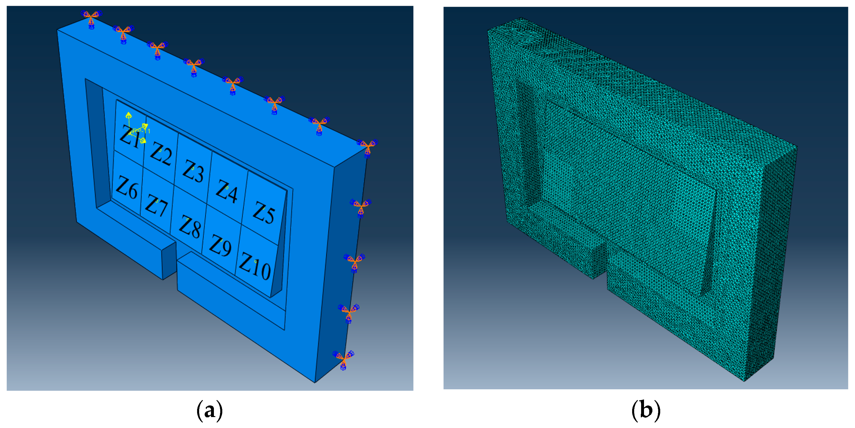
The local machining stability of the three different shaped parts at h = 30 mm was further compared, and the results are shown in Figure 11. The same pattern was found: the maximum shear stress at the bottom was more significant when machining zones 1–4, the maximum shear stress at the bottom was moderate when machining zones 5–6, and the maximum shear stress at the bottom was smaller when machining zones 7–10. In addition, the maximum shear stress of the drum-shaped parts when machining all zones (except zone 9) was the smallest among the three forms of parts, while the maximum shear stress of the saddle-shaped parts when machining all zones (except zone 9) was the largest. It implied that the drum-shaped parts were the most difficult to hold, while the saddle-shaped parts were the easiest to maintain.
Whether it is a standard, drum or saddle-shaped part, zones 6–10 of the part are thicker. Therefore, the cutting force is spread over more area, and the shear stress at the bottom is significantly less than zones 1–5. In addition, we applied cutting force Fx in the x-direction. When machining up to zone 5, the short edge of the false boss (next to Z5) acted as a larger dispersion of the cutting force. When machining the Z1–Z4 area, the short side of the false boss (next to Z5) was farther away, and Fx was mainly supported by the long side (much thinner). It was easy to cause stress concentration. This explains the fact that the maximum stress at the bottom of the tab decreases significantly when machining areas beyond 4.

5. Conclusions

In this paper, a simulation model is established for the false boss machining process of Nomex honeycomb core parts. The finite element model’s reliability is demonstrated through this process’s experiments. Based on the proposed simulation model, the weak points of the false boss machining of honeycomb composites under different machining regions are investigated. In addition, considering the effect of differently shaped parts, this paper analyzes to obtain a reasonable critical parameter h of false boss. The following major conclusions can be drawn from this work.
  • For standard-shaped workpieces, the critical parameter h = 28–32 mm can meet the fixation requirements, while the machining stability cannot be guaranteed with h ≤ 26 mm or h ≥ 34 mm.
  • Both too large and too small h are detrimental to the stability of the false boss. As the width of the false boss h increases from 20 mm to 40 mm, the maximum shear stresses of different shaped workpieces show a consistent tendency of decreasing and then increasing. In addition, the minimum value is reached at h = 30 mm.
  • In the surface milling process, the maximum shear stress is different in each local machining region. Zones 1–4 are categorized to instable regions, while zones 5–6 are categorized to transition region, and zones 7–10 are categorized to stable region.
  • For shaped parts machining, the maximum shear stresses when machining each region of drum-shaped parts are generally higher than those of standard parts. The maximum shear stresses when machining each region of saddle-shaped parts are usually lower than those of standard parts. It means that it is more difficult to hold a saddle-shaped part and less challenging to hold a drum-shaped part.

Author Contributions

Conceptualization, X.Y., G.S. and P.F.; methodology, B.L., Y.M. and C.X.; data curation, X.Y., J.X. and Y.L.; writing—original draft preparation, X.Y. and B.L.; writing—review and editing, F.F., B.L. and F.W.; project administration, X.Y., F.F. and P.F. All authors have read and agreed to the published version of the manuscript.

Funding

This study was supported by National Natural Science Foundation of China (52275441) and Shenzhen Science and Technology Program (WDZC20231129101903002).

Data Availability Statement

The data presented in this study are available from the corresponding authors with a reasonable request.

Acknowledgments

The authors would like to thank Xiamen Tungsten Co., Ltd. for their technical support.

Conflicts of Interest

The authors declare no conflicts of interest. Xinman Yuan and Ge Song were employed by the company AVIC Chengdu Aircraft Industrial (Group) Co., Ltd. Yuan Ma and Chao Xu were employed by the company Shenzhen Tsingding Technology Co., Ltd. The remaining authors declare that the research was conducted in the absence of any commercial or financial relationships that could be construed as a potential conflict of interest.

References

  1. Zhao, Y.; Liu, Q.; Xu, Z.; Ji, G.; Mo, R. A Split-Ring Resonator-Loaded Honeycomb Sandwich Structure for Broadband Microwave Absorption. Coatings 2022, 12, 1706. [Google Scholar] [CrossRef]
  2. Zhang, C.; Yang, Y.; Luo, S.; Cheng, C.; Wang, S.; Liu, B. Fabrication of superhydrophobic composite membranes with honeycomb porous structure for oil/water separation. Coatings 2022, 12, 1698. [Google Scholar] [CrossRef]
  3. Ahmad, S.; Zhang, J.; Feng, P.; Yu, D.; Wu, Z.; Ke, M. Processing technologies for Nomex honeycomb composites (NHCs): A critical review. Compos. Struct. 2020, 250, 112545. [Google Scholar] [CrossRef]
  4. Xu, J.; Yue, Q.; Zha, H.; Yuan, X.; Cai, X.; Xu, C.; Ma, Y.; Feng, P.; Feng, F. Wear reduction by toughness enhancement of disc tool in Nomex honeycomb composites machining. Tribol. Int. 2023, 185, 108475. [Google Scholar] [CrossRef]
  5. Xu, J.; Wang, C.; Feng, P.; Jiang, E.; Feng, F. Meso-scale cracks initiation of Nomex honeycomb composites in orthogonal cutting with a straight blade cutter. Compos. Sci. Technol. 2023, 233, 109914. [Google Scholar] [CrossRef]
  6. Liu, G.; Yang, J.; Zhang, L.; Gao, Q.; Qian, L.; Zhang, R. Surface Quality Experimental Study on Rotary Ultrasonic Machining of Honeycomb Composites with a Circular Knife Cutting Tool. Crystals 2022, 12, 725. [Google Scholar] [CrossRef]
  7. Chang, S.-Y.; Chen, C.-D.; Yeh, J.-Y.; Chen, L.-W. Elastic wave propagation of two-dimensional metamaterials composed of auxetic star-shaped honeycomb structures. Crystals 2019, 9, 121. [Google Scholar] [CrossRef]
  8. Yue, S.; Bai, Y.; Du, Z.; Zou, H.; Shi, W.; Zheng, G. Dynamic Behavior of Kinetic Projectile Impact on Honeycomb Sandwich Panels and Multi-Layer Plates. Crystals 2022, 12, 572. [Google Scholar] [CrossRef]
  9. Guo, J.; Sun, J.; Du, H. Cutting Force Reduction Mechanism in Ultrasonic Cutting of Aramid Honeycomb. Int. Mech. Sci. 2024, 273, 109317. [Google Scholar] [CrossRef]
  10. Sun, J.; Wang, Y.; Zhou, P. Equivalent mechanical model of resin-coated aramid paper of Nomex honeycomb. Int. Mech. Sci. 2023, 240, 107935. [Google Scholar] [CrossRef]
  11. Jie, X.U.; Bo, L.I.; Pingfa, F.E.; Qiang, W.A.; Feng, F.E. A novel method for AFRPs burrs removal: Principle of mechanochemo-induced fiber fracture. Chin. J. Aeronaut. 2024; in press. [Google Scholar]
  12. Ma, K.; Wang, J.; Zhang, J.; Feng, P.; Yu, D.; Ahmad, S. A force-insensitive impedance compensation method for giant magnetostriction ultrasonic cutting system of Nomex honeycomb composites. Compos. Struct. 2022, 294, 115708. [Google Scholar] [CrossRef]
  13. Li, Y.; Li, F.; He, Y. Geometrically nonlinear forced vibrations of the symmetric rectangular honeycomb sandwich panels with completed clamped supported boundaries. Compos. Struct. 2011, 93, 360–368. [Google Scholar] [CrossRef]
  14. Do, M.D.; Son, Y.; Choi, H.-J. Optimal workpiece positioning in flexible fixtures for thin-walled components. Comput.-Aided Des. 2018, 95, 14–23. [Google Scholar] [CrossRef]
  15. Ramnath, B.V.; Elanchezhian, C.; Rajesh, S.; Prakash, S.J.; Kumaar, B.M.; Rajeshkannan, K. Design and development of milling fixture for friction stir welding. Mater. Today: Proc. 2018, 5, 1832–1838. [Google Scholar]
  16. Zhang, K.; Wu, D.; Wang, J. Research on machining fixture layout optimization for near-net-shaped jet engine blade. In Proceedings of the IOP Conference Series: Materials Science and Engineering, Wuhan, China, 10–12 October 2019. [Google Scholar]
  17. Naeem, A.; Pasha, R.A.; Muneeb, M. A novel milling fixture pallet system for production growth of alligator forceps: Design, manufacturing, and testing. Results Eng. 2022, 16, 100668. [Google Scholar] [CrossRef]
  18. Aoyama, T.; Kakinuma, Y. Development of fixture devices for thin and compliant workpieces. CIRP Ann. 2005, 54, 325–328. [Google Scholar] [CrossRef]
  19. Kang, J.; Chunzheng, D.; Jinxing, K.; Yi, C.; Yuwen, S.; Shanglin, W. Prediction of clamping deformation in vacuum fixture–workpiece system for low-rigidity thin-walled precision parts using finite element method. Int. J. Adv. Manuf. Technol. 2020, 109, 1895–1916. [Google Scholar] [CrossRef]
  20. Fritzsche, R.; Voigt, E.; Schaffrath, R.; Todtermuschke, M.; Röber, M. Automated design of product-flexible car body fixtures with software-supported part alignment using particle swarm optimization. Procedia CIRP 2020, 88, 157–162. [Google Scholar] [CrossRef]
  21. Singh, M.; Singh, A.K. Performance investigation of magnetorheological finishing of rolls surface in cold rolling process. J. Manuf. Process. 2019, 41, 315–329. [Google Scholar] [CrossRef]
  22. Yadav, R.D.; Singh, A.K.; Arora, K. Parametric analysis of magnetorheological finishing process for improved performance of gear profile. J. Manuf. Process. 2020, 57, 254–267. [Google Scholar] [CrossRef]
  23. Ma, J.; Zhang, D.; Wu, B.; Luo, M.; Chen, B. Vibration suppression of thin-walled workpiece machining considering external damping properties based on magnetorheological fluids flexible fixture. Chin. J. Aeronaut. 2016, 29, 1074–1083. [Google Scholar] [CrossRef]
  24. Liu, H.; Wang, C.; Han, L.; Wang, S.; Liu, K.; Wang, Y. The influence of ice-based fixture on suppressing machining-induced deformation of cantilever thin-walled parts: A novel and green fixture. Int. J. Adv. Manuf. Technol. 2021, 117, 329–341. [Google Scholar] [CrossRef]
  25. Liu, H.; Wang, C.; Zeng, L.; Li, P.; Wang, S.; Sun, K.; Wang, Y. Prediction of icing interface normal stress response for thin-walled parts machining with ice-based fixturing (IBF). Thin-Walled Struct. 2023, 188, 110807. [Google Scholar] [CrossRef]
  26. Hu, F.; Li, D. Process planning and simulation strategies for perimeter milling of thin-walled flexible parts held by reconfigurable fixturing system. In Proceedings of the 2011 Third International Conference on Measuring Technology and Mechatronics Automation, Shanghai, China, 6–7 January 2011; pp. 922–926. [Google Scholar]
  27. Liu, G.; Ke, Y.-L. Study on clamping method for paper honeycomb based on magnetic field and friction principle. J. Mater. Process. Technol. 2007, 190, 65–72. [Google Scholar] [CrossRef]
  28. Tavares, S.S.; Caillet-Bois, N.; Michaud, V.; Månson, J.-A. Vacuum-bag processing of sandwich structures: Role of honeycomb pressure level on skin–core adhesion and skin quality. Compos. Sci. Technol. 2010, 70, 797–803. [Google Scholar] [CrossRef]
  29. Armstrong, K.B.; Cole, W.; Chesmar, E.; Museux, F. Care and Repair of Advanced Composites; SAE International: Warrendale, PA, USA, 2020. [Google Scholar]
  30. Jin, C.Z. Study on reliability of new fixture method for NOMEX honeycomb. Adv. Mater. Res. 2012, 415, 3–13. [Google Scholar] [CrossRef]
  31. Jiang, E.; Yue, Q.; Xu, J.; Fan, C.; Song, G.; Yuan, X.; Ma, Y.; Yu, X.; Yang, P.; Feng, P. A wear testing method of straight blade tools for Nomex honeycomb composites machining. Wear 2024, 546, 205325. [Google Scholar] [CrossRef]
  32. Xu, Y.; Zhang, J.; Zhang, Q.; Huang, S.; Wu, Y.; He, J. Theoretical and experimental investigations of tool wear in ultrasonic vibration–assisted turning of 304 austenitic stainless steel. Int. J. Adv. Manuf. Technol. 2023, 127, 1–25. [Google Scholar] [CrossRef]
  33. Malek, S.; Gibson, L. Effective elastic properties of periodic hexagonal honeycombs. Mech. Mater. 2015, 91, 226–240. [Google Scholar] [CrossRef]
  34. Gibson, L.J. Modelling the mechanical behavior of cellular materials. Mater. Sci. Eng. A 1989, 110, 1–36. [Google Scholar] [CrossRef]
  35. Gibson, L.J.; Ashby, M.F.; Schajer, G.; Robertson, C. The mechanics of two-dimensional cellular materials. Proc. R. Soc. London. A. Math. Phys. Sci. 1982, 382, 25–42. [Google Scholar]
  36. Kelsey, S.; Gellatly, R.; Clark, B. The shear modulus of foil honeycomb cores: A theoretical and experimental investigation on cores used in sandwich construction. Aircr. Eng. Aerosp. Technol. 1958, 30, 294–302. [Google Scholar] [CrossRef]
Figure 1. (a) Geometry of equal-wall-thickness honeycomb; (b) Geometry of double-wall-thickness honeycomb.
Jcs 08 00292 g001
Figure 2. (a) Workpiece retention solution based on the false boss connection; (b) Process of honeycomb core parts machining based on the false boss connection.
Jcs 08 00292 g002
Figure 3. Structure of the false boss model.
Jcs 08 00292 g003
Figure 4. (a) Area division of surface I, (b) Meshing of honeycomb core part and false boss.
Jcs 08 00292 g004
Figure 5. Disc cutter structure.
Jcs 08 00292 g005
Figure 6. (a) Experimental platform, (b) Results of cutting forces.
Jcs 08 00292 g006
Figure 7. (a) NRH-3-48 Nomex honeycomb core, (b) Experimental platform, (c) Boss bonding area division.
Jcs 08 00292 g007
Figure 8. (a) Max shear stress when machining to zone 3, (b) Average shear stress in different h.
Jcs 08 00292 g008
Figure 9. Average shear stress of 10 zones when h = 20–40 mm.
Jcs 08 00292 g009
Figure 10. (a) Drum-like part, (b) Standard part, (c) Saddle-like part.
Jcs 08 00292 g010
Figure 11. Max shear stress for different morphological parts at h = 30 mm when machining from zone 1 to zone 10 (MPa).
Jcs 08 00292 g011
Table 1. Parameters for constitutive model.
θ (°) h = l (mm) t (mm) E s (MPa) ν s G s (MPa)
601.830.12530000.3623
Table 2. Parameters for the false boss.
a (mm)b (mm)D1 (mm)D2 (mm)εh (mm)
20010012141.520–40
Table 3. Parameters for the disc cutter.
MaterialHardness (HRC)Impact Toughness (MJ/m2) d (mm) θ (°)hdisc (mm)
W18Cr4V1.830.18–0.3227131
Table 4. Experiment results (Jcs 08 00292 i001 indicated that the area was not debonded, ▲ indicated that the area appeared to be debonded).
Number h   ( m m ) Results
B1B2B3B4B5B6B7B8
120Jcs 08 00292 i001Jcs 08 00292 i001Jcs 08 00292 i001
222Jcs 08 00292 i001Jcs 08 00292 i001Jcs 08 00292 i001Jcs 08 00292 i001Jcs 08 00292 i001
324Jcs 08 00292 i001Jcs 08 00292 i001Jcs 08 00292 i001Jcs 08 00292 i001Jcs 08 00292 i001Jcs 08 00292 i001
426Jcs 08 00292 i001Jcs 08 00292 i001Jcs 08 00292 i001Jcs 08 00292 i001Jcs 08 00292 i001Jcs 08 00292 i001Jcs 08 00292 i001
528Jcs 08 00292 i001Jcs 08 00292 i001Jcs 08 00292 i001Jcs 08 00292 i001Jcs 08 00292 i001Jcs 08 00292 i001Jcs 08 00292 i001Jcs 08 00292 i001
630Jcs 08 00292 i001Jcs 08 00292 i001Jcs 08 00292 i001Jcs 08 00292 i001Jcs 08 00292 i001Jcs 08 00292 i001Jcs 08 00292 i001Jcs 08 00292 i001
732Jcs 08 00292 i001Jcs 08 00292 i001Jcs 08 00292 i001Jcs 08 00292 i001Jcs 08 00292 i001Jcs 08 00292 i001Jcs 08 00292 i001Jcs 08 00292 i001
834Jcs 08 00292 i001Jcs 08 00292 i001Jcs 08 00292 i001Jcs 08 00292 i001Jcs 08 00292 i001Jcs 08 00292 i001Jcs 08 00292 i001
936Jcs 08 00292 i001Jcs 08 00292 i001Jcs 08 00292 i001Jcs 08 00292 i001Jcs 08 00292 i001Jcs 08 00292 i001
1038Jcs 08 00292 i001Jcs 08 00292 i001Jcs 08 00292 i001Jcs 08 00292 i001
1140Jcs 08 00292 i001Jcs 08 00292 i001Jcs 08 00292 i001Jcs 08 00292 i001Jcs 08 00292 i001
Table 5. Maximum shear stress at the bottom of false boss II (10−2 MPa).
Z1Z2Z3Z4Z5Z6Z7Z8Z9Z10
h = 20 mm 2.8953.2043.4673.4092.1691.9421.2010.9910.8251.070
h = 25 mm 2.8413.0083.2663.1312.1392.0090.9310.7770.9171.047
h = 30 mm 2.8112.9543.1423.0232.1611.9330.8890.870.8240.979
h = 35 mm 2.8772.9043.3773.1802.0772.1830.9420.8490.8581.019
h = 40 mm 2.9413.0083.3743.2072.1551.6441.0381.0550.8781.034
Table 6. Maximum shear stress at the bottom of false boss II for the drum-shaped part when machining from zone 1 to zone 10 (10−2 MPa).
Z1Z2Z3Z4Z5Z6Z7Z8Z9Z10
h = 20 mm 2.5642.7812.8092.81.3631.6481.0440.9330.6251.135
h = 25 mm 2.5192.5852.6142.5241.3321.7080.7750.7130.7151.113
h = 30 mm 2.4832.5242.582.4141.3531.6360.7210.8090.6271.041
h = 35 mm 2.5512.4782.7232.571.2731.8890.7850.780.6531.087
h = 40 mm 2.6852.5812.7112.7521.3571.5970.8740.9990.7041.107
Table 7. Maximum shear stress at the bottom of false boss II for the saddle-shaped part when machining from zone 1 to zone 10 (10−2 MPa).
Z1Z2Z3Z4Z5Z6Z7Z8Z9Z10
h = 20 mm 3.4163.8394.3334.2663.1862.671.5911.251.0281.242
h = 25 mm 3.4163.7034.1793.9973.082.481.3331.0161.3061.193
h = 30 mm 3.3953.6514.0223.8323.1992.3721.2590.9571.2191.135
h = 35 mm 3.4523.5744.3064.0333.1112.5741.31.161.2781.242
h = 40 mm 3.4453.6884.2633.8853.2081.9491.4131.3611.2441.085
Disclaimer/Publisher’s Note: The statements, opinions and data contained in all publications are solely those of the individual author(s) and contributor(s) and not of MDPI and/or the editor(s). MDPI and/or the editor(s) disclaim responsibility for any injury to people or property resulting from any ideas, methods, instructions or products referred to in the content.

