
Examining Mechanical Property Differences in Concrete with Natural and Synthetic Fiber Additives

 ,
,  ,
,  ,
,
Abstract
1. Introduction
2. Experimental Program
2.1. Materials
2.1.1. Cement and Admixtures
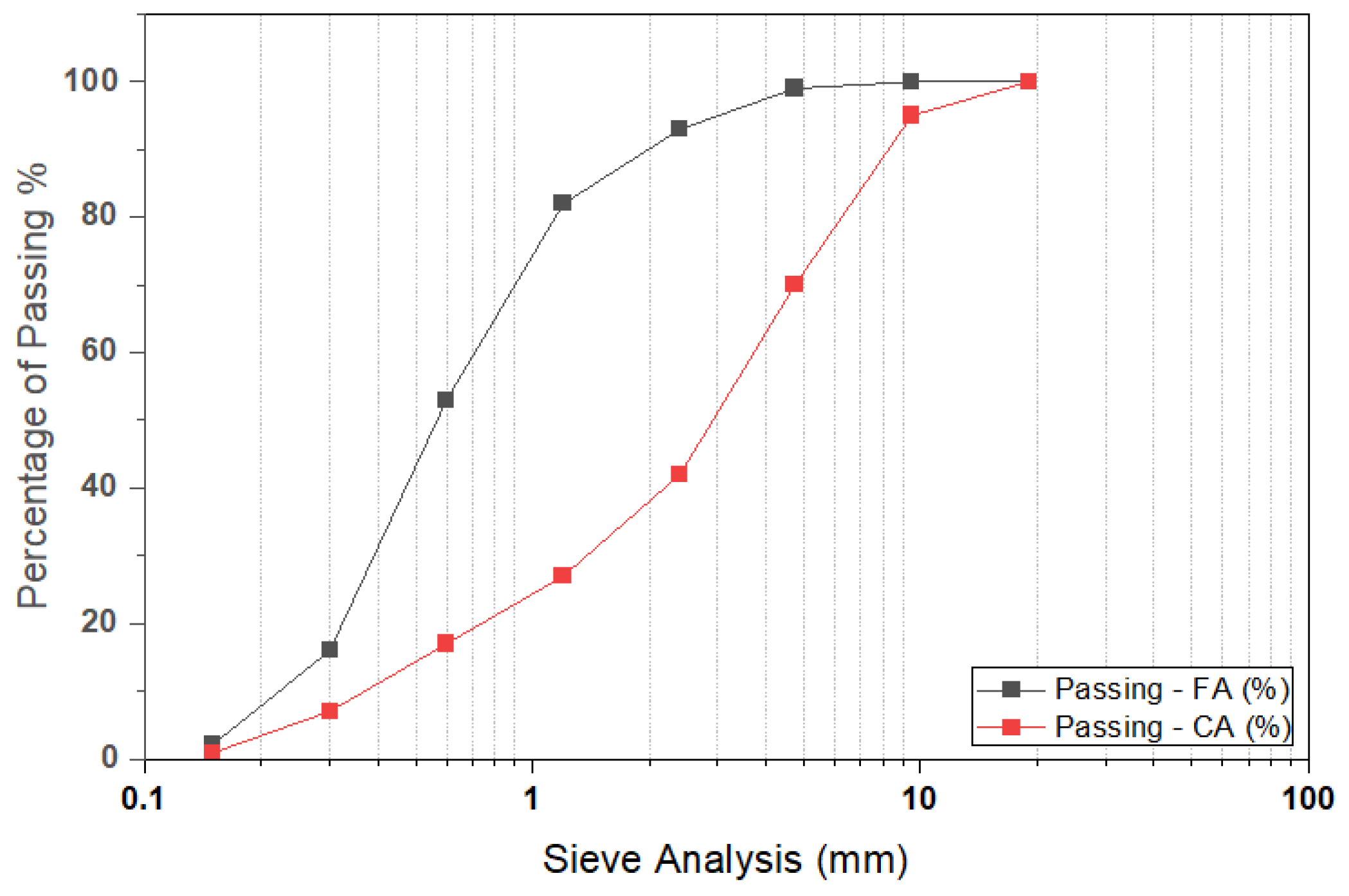
2.1.2. Aggregates
2.1.3. Properties of Fibers
2.2. Mixture Proportions
2.3. Preparation of the Specimens and Test Procedures
2.3.1. Workability
2.3.2. Compressive Strength
2.3.3. Flexural Strength
2.3.4. Splitting Tensile Strength
2.3.5. Water Absorption
2.3.6. SEM Observation
3. Results and Discussions
3.1. Workability
3.2. Water Absorption
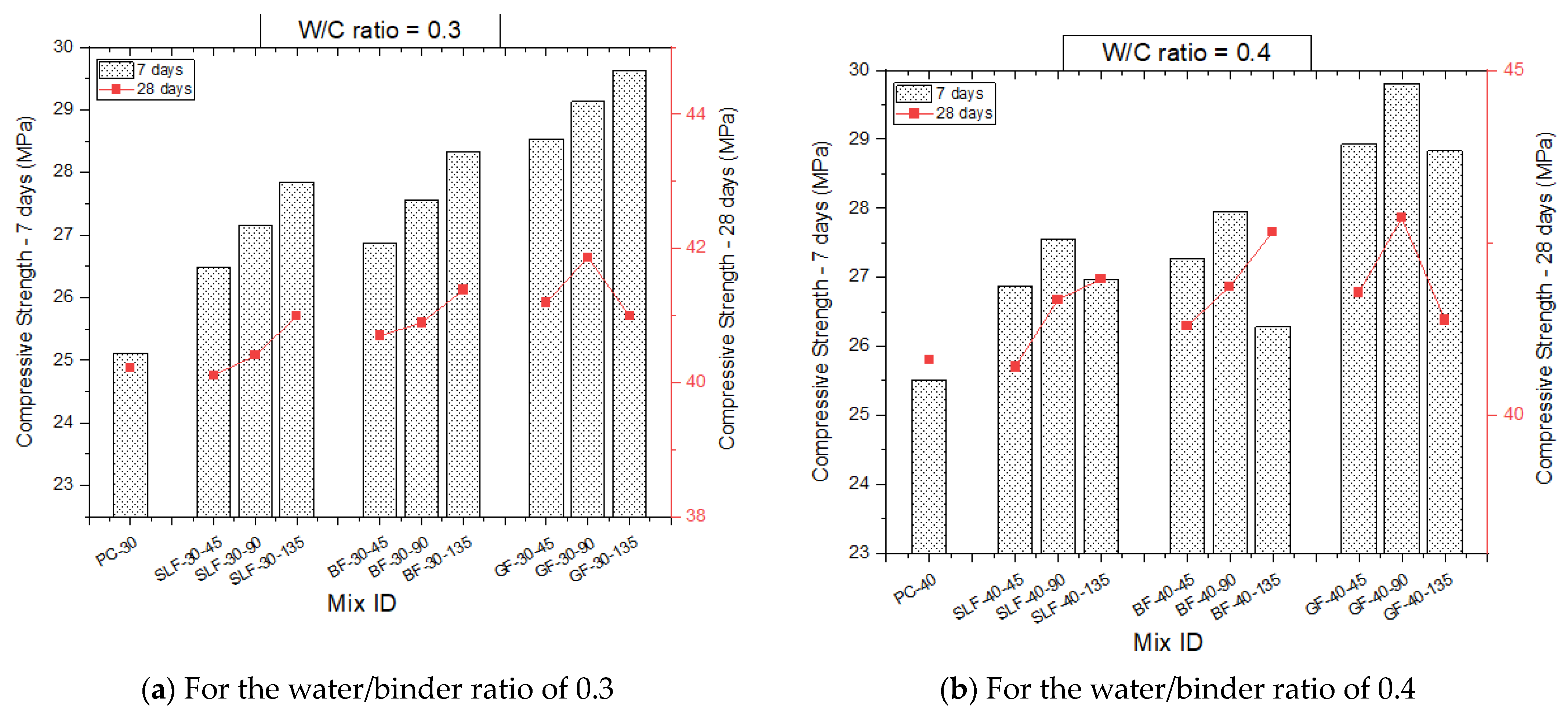
3.3. Compressive Strength
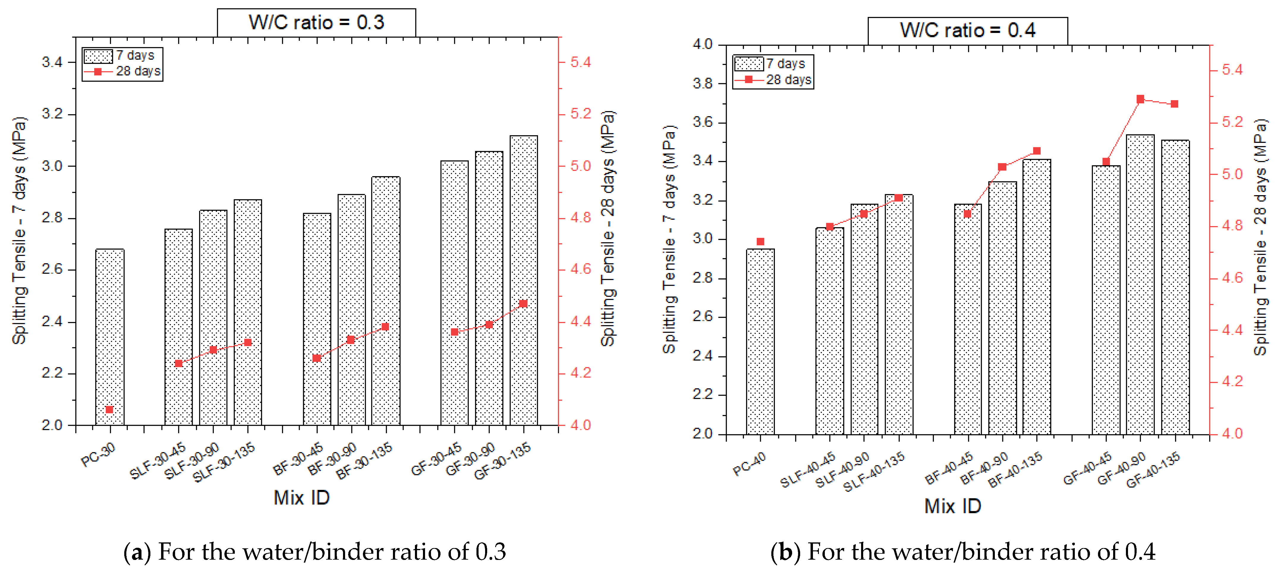
3.4. Splitting Tensile Strength
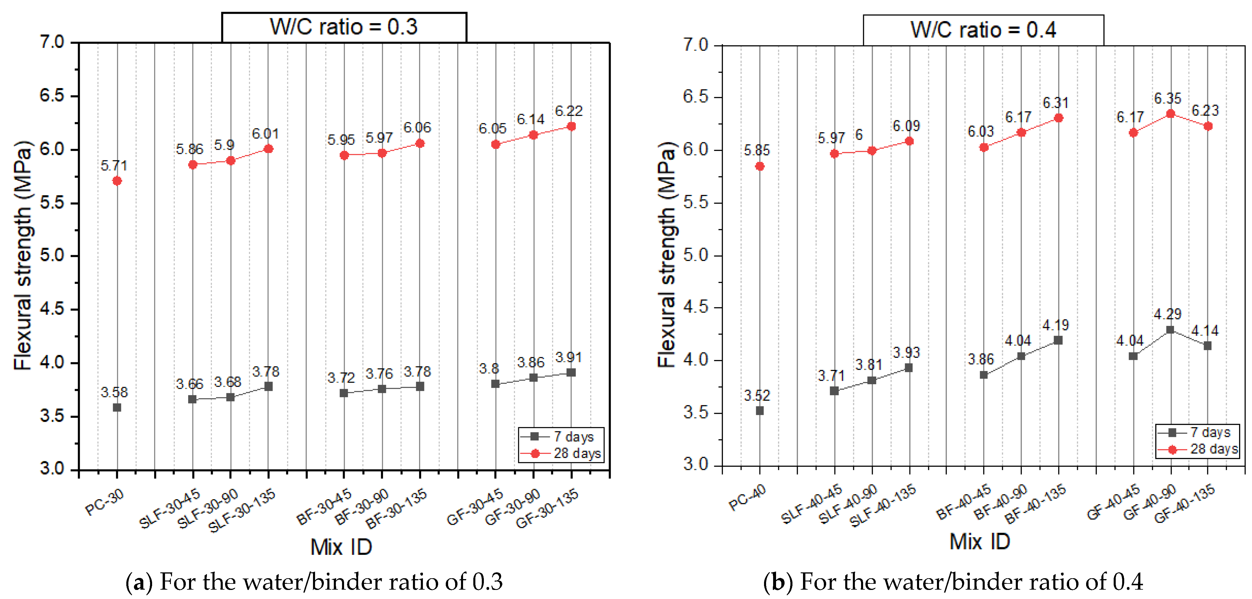
3.5. Flexural Strength
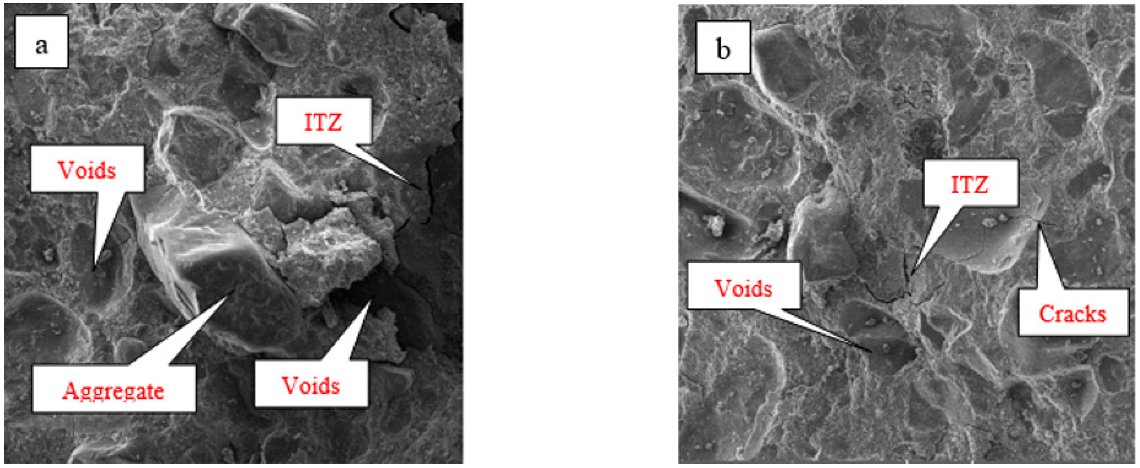
3.6. Micromorphology Analysis
4. Conclusions
- The reduction in workability was enhanced in the cases of SLF and BF relative to the case of GF. This could be attributed to the water absorption by the SLF and BF. The inherent characteristics of SLF and BF as plant fibers with a higher water absorption capacity led to these reductions in workability.
- The relationship between the water absorption of SLF and BF and the concrete absorption was a crucial aspect that influenced the overall performance of concrete. As the percentage of these fibers increased, there were rises in the water absorption of concrete.
- The outcomes revealed significant enhancements in the mechanical properties of SLFC and BFC compared to the non-fiber concrete. Moreover, these properties increased with the escalating of the fiber content. Higher improvements were obtained for the GFC relative to the SLFC and BFC specimens with the same fiber content.
- The micromorphology of the samples with SLF and BF revealed loosely bonded connections between the fibers and the matrix, which contributed to the degradation of the concrete’s strength properties. The adhesive strength between the fibers and the cement matrix was significantly lower than that of the control sample due to the weak cohesive strength between fibers and concrete.
5. Limitations and Future Work
Author Contributions
Funding
Data Availability Statement
Acknowledgments
Conflicts of Interest
References
- Thomas, B.C.; Jose, Y.S. Materials Today: Proceedings A study on characteristics of sisal fiber and its performance in fiber reinforced concrete. Mater. Today Proc. 2021, 51, 1238–1242. [Google Scholar] [CrossRef]
- Kabir, R.; Islam, M. Bond stress behavior between concrete and steel rebar: Critical investigation of pull-out test via Finite Element Modeling. Int. J. Civ. Struct. Eng. 2014, 5, 80–90. [Google Scholar] [CrossRef]
- de Klerk, M.D.; Kayondo, M.; Moelich, G.M.; de Villiers, W.I.; Combrinck, R.; Boshoff, W.P. Durability of chemically modified sisal fibre in cement-based composites. Constr. Build. Mater. 2020, 241, 117835. [Google Scholar] [CrossRef]
- De Souza, R.; Maria, L.; De Souza, S.; De Andrade, F. Comparative study on the mechanical behavior and durability of polypropylene and sisal fiber reinforced concretes. Constr. Build. Mater. 2019, 211, 617–628. [Google Scholar] [CrossRef]
- Lima, P.R.L.; Roque, A.B.; Fontes, C.M.A.; Lima, J.M.F.; Barros, J.A.O. Potentialities of cement-based recycled materials reinforced with sisal fibers as a filler component of precast concrete slabs. In Sustainable and Nonconventional Construction Materials Using Inorganic Bonded Fiber Composites; Woodhead Publishing: Sawston, Cambridge, 2017; pp. 399–428. [Google Scholar] [CrossRef]
- Sabarish, K.V.; Paul, P.; Bhuvaneshwari; Jones, J. An experimental investigation on properties of sisal fiber used in the concrete. Mater. Today Proc. 2020, 22, 439–443. [Google Scholar] [CrossRef]
- Lima, P.R.L.; Barros, J.A.O.; Roque, A.B.; Fontes, C.M.A.; Lima, J.M.F. Short sisal fiber reinforced recycled concrete block for one-way precast concrete slabs. Constr. Build. Mater. 2018, 187, 620–634. [Google Scholar] [CrossRef]
- Jahim, H. The Use Of Wollastonite To Enhance Fresh And Mechanical Properites of Concrete. Ph.D. Thesis, Baghdad University, Baghdad, Iraq, 2010. [Google Scholar]
- El-azim, A.; El-Aziz, A.; Hasan, F. Mechanical Behavior of Concrete Containing One Type and Hybrid Fibers. Egypt. Int. J. Mech. Behav. Concr. Contain. Type Hybrid Fibers 2018, 24, 27–33. [Google Scholar] [CrossRef]
- Amezugbe, F.A. The Performance of Natural and Synthetic Fibers in Low Strength Mortar: A Pilot Study of Six Selected Fibers. Ph.D. Thesis, University of Florida, Gainesville, FL, USA, 2013; pp. 1–75. [Google Scholar]
- Swathi, V.; Asadi, S.S. An influence of pozzolanic materials with hybrid fibers on structural performance of concrete: A review. Mater. Today Proc. 2020, 43, 1956–1959. [Google Scholar] [CrossRef]
- Padanattil, A.; Jayanarayanan, K.; Mini, K.M. Novel hybrid composites based on glass and sisal fiber for retrofitting of reinforced concrete structures. Constr. Build. Mater. 2017, 133, 146–153. [Google Scholar] [CrossRef]
- Saravanan, R.; Malyadri, T.; Rao, M.S.S.; Sunkara, N. Synthesize and characterization of maleic acid treated banana fiber composites. Mater. Today Proc. 2019, 18, 5382–5387. [Google Scholar] [CrossRef]
- Izquierdo, I.S.; Izquierdo, O.S.; Ramalho, M.A.; Taliercio, A. Sisal fiber reinforced hollow concrete blocks for structural applications: Testing and modeling. Constr. Build. Mater. 2017, 151, 98–112. [Google Scholar] [CrossRef]
- Ren, G.; Yao, B.; Huang, H.; Gao, X. Influence of sisal fibers on the mechanical performance of ultra-high performance concretes. Constr. Build. Mater. 2021, 286, 122958. [Google Scholar] [CrossRef]
- Niyasom, S.; Tangboriboon, N. Development of biomaterial fillers using eggshells, water hyacinth fibers, and banana fibers for green concrete construction. Constr. Build. Mater. 2021, 283, 122627. [Google Scholar] [CrossRef]
- Kumar, S.S.; Akash, B.M.; Kabilan, M.; Karna, H.; Navaneethan, S. An Experimental Study and Behaviour of Banana Fiber in Concrete. Int. J. Sci. Eng. Res. 2019, 10, 10–14. Available online: http://www.ijser.org (accessed on 20 March 2023).
- Mostafa, M.; Uddin, N. Experimental analysis of Compressed Earth Block (CEB) with banana fibers resisting flexural and compression forces. Case Stud. Constr. Mater. 2016, 5, 53–63. [Google Scholar] [CrossRef]
- Akinyemi, B.A.; Dai, C. Development of banana fibers and wood bottom ash modified cement mortars. Constr. Build. Mater. 2020, 241, 118041. [Google Scholar] [CrossRef]
- Chandramouli, K.; Pannirselvam, N.; Pardhu, D.V.V.N.S.; Anitha, V. Experimental investigation on banana fibre reinforced concrete with conventional concrete. Int. J. Recent Technol. Eng. 2019, 7, 874–876. [Google Scholar]
- Dhawan, A.; Gupta, N.; Goyal, R.; Saxena, K.K. Evaluation of mechanical properties of concrete manufactured with fly ash, bagasse ash and banana fibre. Mater. Today Proc. 2021, 44, 17–22. [Google Scholar] [CrossRef]
- Naaamandadin, N.A.; Saharudin, A.I.; Mustafa, W.A.; Santiagoo, R. Mechanical behaviour of banana fibre reinforced concrete with kenaf fibre as an additive. In Lecture Notes in Mechanical Engineering; Springer: Singapore, 2020; pp. 207–213. [Google Scholar] [CrossRef]
- Yue, C.; Hu, X. Tensile properties of short-glass-fiber- and short-carbon-fiber-reinforced polypropylene composites. Compos. Part A Appl. Sci. Manuf. 2000, 31, 1117–1125. [Google Scholar]
- Khan, M.; Ali, M. Use of glass and nylon fibers in concrete for controlling early age micro cracking in bridge decks. Constr. Build. Mater. 2016, 125, 800–808. [Google Scholar] [CrossRef]
- Choi, Y.; Yuan, R.L. Experimental relationship between splitting tensile strength and compressive strength of GFRC and PFRC. Cem. Concr. Res. 2005, 35, 1587–1591. [Google Scholar] [CrossRef]
- Kizilkanat, A.B.; Kabay, N.; Akyüncü, V.; Chowdhury, S.; Akça, A.H. Mechanical properties and fracture behavior of basalt and glass fiber reinforced concrete: An experimental study. Constr. Build. Mater. 2015, 100, 218–224. [Google Scholar] [CrossRef]
- Madhkhan, M.; Katirai, R. Effect of pozzolanic materials on mechanical properties and aging of glass fiber reinforced concrete. Constr. Build. Mater. 2019, 225, 146–158. [Google Scholar] [CrossRef]
- ES 4756-1; Cement Part:(1) Composition, Specifications And Conformity Criteria For Common Cements. Egyptian Organization for Standardization and Quality (EOS): Cairo Governorate, Egypt, 2013.
- EN 197-1; Cement—Part 1: Composition, Specifications and Conformity Criteria for Common Cements Ciment. European Committee For Standardisation: London, UK, 1992.
- Sika ViscoCrete-3425. Available online: https://egy.sika.com/en/construction/concrete-admixture/admixture-types/high-range-waterreducers/sika-viscocrete-3425.html (accessed on 10 April 2022).
- ASTM C494/C494M; Standard Specification for Chemical Admixtures for Concrete. iTeh, Inc.: Newark, DE, USA, 2019. [CrossRef]
- ASTM C33/C33M; Standard Specification for Concrete Aggregates. ASTM International: West Conshohocken, PA, USA,, 2018. [CrossRef]
- ASTM D123; Standard Terminology Relating to Textiles. ASTM International: West Conshohocken, PA, USA, 2019. [CrossRef]
- Attia, M.M.; Al Sayed, A.A.K.A.; Tayeh, B.A.; Shawky, S.M.M. Banana agriculture waste as eco-friendly material in fibre-reinforced concrete: An experimental study. Adv. Concr. Constr. 2022, 14, 355–368. [Google Scholar] [CrossRef]
- ACI 211.1-91; Standard Practice for Selecting Proportions for Normal, Heavyweight, and Mass Concrete. ACI Committee 211; American Concrete Institute: Farmington Hills, MI, USA, 2002.
- ACI PRC-544.1R-96; Report on Fiber Reinforced Concrete. American Concrete Institute: Farmington Hills, MI, USA, 2009.
- ASTM C143/C143M; Standard Test Method for Slump of Hydraulic-Cement Concrete. ASTM International: West Conshohocken, PA, USA, 2015. [CrossRef]
- BS 1881-124; Testing Concrete—Methods for Analysis of Hardened Concrete. British Standards Institution (BSI): London, UK, 2021.
- ASTM C78/C78M; Standard Test Method for Flexural Strength of Concrete. ASTM International: West Conshohocken, PA, USA, 2022. [CrossRef]
- ASTM C496/C496M; Standard Test Method for Splitting Tensile Strength of Cylindrical Concrete Specimens. ASTM International: West Conshohocken, PA, USA, 2011. [CrossRef]
- ASTM C642; Standard Test Method for Density, Absorption, and Voids in Hardened Concrete. ASTM International: West Conshohocken, PA, USA, 2021. [CrossRef]
- ASTM C1723; Standard Guide for Examination of Hardened Concrete Using Scanning Electron Microscopy. iTeh, Inc.: Newark, DE, USA, 2016. [CrossRef]
- Paktiawal, A.; Alam, M. Alkali-resistant glass fiber high strength concrete and its durability parameters. Mater. Today Proc. 2021, 47, 4758–4766. [Google Scholar] [CrossRef]
- Yuan, Z.; Jia, Y. Mechanical properties and microstructure of glass fiber and polypropylene fiber reinforced concrete: An experimental study. Constr. Build. Mater. 2021, 266, 121048. [Google Scholar] [CrossRef]
- Anand, S.; Varshney, H. An Experimental Evaluation on Effect of Chopped Glass Fiber in Conventional Concrete. Int. J. Adv. Res. Sci. Eng. 2018, 7, 556–562. [Google Scholar]
- Griffiths, R.; Ball, A. An assessment of the properties and degradation behaviour of glass-fibre-reinforced polyester polymer concrete. Compos. Sci. Technol. 2000, 60, 2747–2753. [Google Scholar] [CrossRef]


| Cement | SiO2 | Al2O3 | Fe2O3 | CaO | MgO | SO3 | K2O | Na2O | LOI * |
|---|---|---|---|---|---|---|---|---|---|
| I 42.5N | 21.3 | 4.7 | 3.9 | 63.7 | 1.8 | 2.5 | 0.48 | 0.18 | 3.1 |
| Property | Coarse Aggregate | Fine Aggregate |
|---|---|---|
| Specific gravity | 2.6 | 2.5 |
| Volume density (Kg/m3) | 1430 | 1612 |
| Water absorption % | 0.8 | 1.9 |
| Los Angeles abrasion % | 17.5 | - |
| Crushing value % | 17.9 | - |
| Fiber Type | Sisal Fiber | Banana Fibers [33] | Glass Fiber |
|---|---|---|---|
| SLF | BF | GF | |
| Mechanical Properties | |||
| Tensile Strength (MPa) | 380 | 754 | 1755 |
| Young’s modulus (GPa) | 5.24 | 27 | 78.51 |
| Elongation Break (%) | 15.9 | 10.35 | 17.2 |
| * L/D ratio | 160 | 150 | 980 |
| Physical Properties | |||
| Density (Kg/m3) | 1450 | 1350 | 2550 |
| Moisture content | 10.47 | 10 | 0.6 |
| Water absorption (%) | 80.5 | 61.2 | 38.7 |
| Width or Diameter (µm) | 250–650 | 80–250 | 13.8 |
| Chemical Composition (%) | |||
| Cellulose | 65 | 63.2 | -- |
| Hemicellulose | 12 | 18.6 | -- |
| Waxes | 2 | 0.3 | -- |
| Lignin | 9.9 | 5.10 | -- |
| Mix. ID | W/B | % Fiber by Vol. | Cement | Sand | Coarse agg. | Water | SP | ||
|---|---|---|---|---|---|---|---|---|---|
| SLF | BF | GF | Kgm−3 | Kgm−3 | Kgm−3 | Kgm−3 | Kgm−3 | ||
| Phase I—W/B ratio 0.30 | |||||||||
| PC-30 | 0.35 | -- | -- | -- | 450 | 800 | 1145 | 135 | 8 |
| SLF-30-45 | 0.30 | 0.45 | -- | -- | 450 | 800 | 1145 | 135 | 8 |
| SLF-30-90 | 0.30 | -- | 0.90 | 450 | 800 | 1145 | 135 | 8 | |
| SLF-30-135 | 0.30 | -- | -- | 1.35 | 450 | 800 | 1145 | 135 | 8 |
| BF-30-45 | 0.30 | 0.45 | -- | -- | 450 | 800 | 1145 | 135 | 8 |
| BF-30-90 | 0.30 | -- | 0.90 | 450 | 800 | 1145 | 135 | 8 | |
| BF-30-135 | 0.30 | -- | -- | 1.35 | 450 | 800 | 1145 | 135 | 8 |
| GF-30-45 | 0.30 | 0.45 | -- | -- | 450 | 800 | 1145 | 135 | 8 |
| GF-30-90 | 0.30 | -- | 0.90 | -- | 450 | 800 | 1145 | 135 | 8 |
| GF-30-135 | 0.30 | -- | -- | 1.35 | 450 | 800 | 1145 | 135 | 8 |
| Phase II—W/B ratio 0.40 | |||||||||
| PC-40 | 0.40 | -- | -- | -- | 450 | 750 | 1080 | 180 | 7 |
| SLF-40-45 | 0.40 | 0.45 | -- | -- | 450 | 750 | 1080 | 180 | 7 |
| SLF-40-90 | 0.40 | -- | 0.90 | 450 | 750 | 1080 | 180 | 7 | |
| SLF-40-135 | 0.40 | -- | -- | 1.35 | 450 | 750 | 1080 | 180 | 7 |
| BF-40-45 | 0.40 | 0.45 | -- | -- | 450 | 750 | 1080 | 180 | 7 |
| BF-40-90 | 0.40 | -- | 0.90 | 450 | 750 | 1080 | 180 | 7 | |
| BF-40-135 | 0.40 | -- | -- | 1.35 | 450 | 750 | 1080 | 180 | 7 |
| GF-40-45 | 0.40 | 0.45 | -- | -- | 450 | 750 | 1080 | 180 | 7 |
| GF-40-90 | 0.40 | -- | 0.90 | -- | 450 | 750 | 1080 | 180 | 7 |
| GF-40-135 | 0.40 | -- | -- | 1.35 | 450 | 750 | 1080 | 180 | 7 |
| Test | Size of Specimens | Fiber Length | Volume % of Fiber | Total Number |
|---|---|---|---|---|
| Compressive Strength | Cubes 100 × 100 × 100 | 35 mm length | 0.45, 0.9, and 1.35 | 72 |
| Flexural Strength | Prisms 100 × 100 × 400 | 35 mm length | 0.45, 0.9, and 1.35 | 72 |
| Splitting tensile strength | Cylinders 150 × 300 | 35 mm length | 0.45, 0.9, and 1.35 | 72 |
| Absorption % | Cubes 100 × 100 × 100 | 35 mm length | 0.45, 0.9, and 1.35 | 72 |
| SEM—28 days | 20 × 15 × 10 | 35 mm length | 0.45, 0.9, and 1.35 | 9 |
| Total number of concrete samples | 279 | |||
| Mix Designation | Slump (mm) | Absorption (%) | f′c (MPa) | fr (MPa) | fspt (MPa) | ||||
|---|---|---|---|---|---|---|---|---|---|
| 7 Days | 28 Days | 7 Days | 28 Days | 7 Days | 28 Days | 7 Days | 28 Days | ||
| Phase I—W/B ratio 0.30 | |||||||||
| PC-30 | 137 | 2.44 | 2.46 | 25.11 | 40.21 | 3.58 | 5.71 | 2.68 | 4.06 |
| SLF-30-45 | 131 | 2.42 | 2.45 | 26.48 | 40.11 | 3.66 | 5.86 | 2.76 | 4.24 |
| SLF-30-90 | 122 | 2.38 | 2.48 | 27.16 | 40.4 | 3.68 | 5.9 | 2.83 | 4.29 |
| SLF-30-135 | 98 | 2.37 | 2.53 | 27.85 | 40.99 | 3.78 | 6.01 | 2.87 | 4.32 |
| BF-30-45 | 123 | 2.38 | 2.47 | 26.87 | 40.7 | 3.72 | 5.95 | 2.82 | 4.26 |
| BF-30-90 | 117 | 2.36 | 2.50 | 27.56 | 40.89 | 3.76 | 5.97 | 2.89 | 4.33 |
| BF-30-135 | 95 | 2.35 | 2.54 | 28.34 | 41.38 | 3.78 | 6.06 | 2.96 | 4.38 |
| GF-30-45 | 136 | 2.44 | 2.41 | 28.54 | 41.19 | 3.8 | 6.05 | 3.02 | 4.36 |
| GF-30-90 | 132 | 2.45 | 2.37 | 29.13 | 41.87 | 3.86 | 6.14 | 3.06 | 4.39 |
| GF-30-135 | 110 | 2.47 | 2.31 | 29.62 | 40.99 | 3.91 | 6.22 | 3.12 | 4.47 |
| Phase II—W/B ratio 0.40 | |||||||||
| PC-40 | 158 | 2.42 | 2.44 | 25.5 | 40.8 | 3.52 | 5.85 | 2.95 | 4.74 |
| SLF-40-45 | 147 | 2.41 | 2.42 | 26.87 | 40.7 | 3.71 | 5.97 | 3.06 | 4.8 |
| SLF-40-90 | 140 | 2.36 | 2.43 | 27.56 | 41.68 | 3.81 | 6 | 3.18 | 4.85 |
| SLF-40-135 | 128 | 2.30 | 2.47 | 26.97 | 41.97 | 3.93 | 6.09 | 3.23 | 4.91 |
| BF-40-45 | 141 | 2.34 | 2.36 | 27.26 | 41.29 | 3.86 | 6.03 | 3.18 | 4.85 |
| BF-40-90 | 132 | 2.27 | 2.39 | 27.95 | 41.87 | 4.04 | 6.17 | 3.3 | 5.03 |
| BF-40-135 | 127 | 2.22 | 2.51 | 26.28 | 42.66 | 4.19 | 6.31 | 3.41 | 5.09 |
| GF-40-45 | 154 | 2.32 | 2.41 | 28.93 | 41.78 | 4.04 | 6.17 | 3.38 | 5.05 |
| GF-40-90 | 141 | 2.21 | 2.36 | 29.81 | 42.86 | 4.29 | 6.35 | 3.54 | 5.29 |
| GF-40-135 | 127 | 2.18 | 2.31 | 28.83 | 41.38 | 4.14 | 6.23 | 3.51 | 5.27 |
Disclaimer/Publisher’s Note: The statements, opinions and data contained in all publications are solely those of the individual author(s) and contributor(s) and not of MDPI and/or the editor(s). MDPI and/or the editor(s) disclaim responsibility for any injury to people or property resulting from any ideas, methods, instructions or products referred to in the content. |
© 2024 by the authors. Licensee MDPI, Basel, Switzerland. This article is an open access article distributed under the terms and conditions of the Creative Commons Attribution (CC BY) license (https://creativecommons.org/licenses/by/4.0/).
Share and Cite
Edris, W.F.; Elbialy, S.; El-Zohairy, A.; Soliman, A.M.; Shawky, S.M.M.; Selouma, T.I.; Al Sayed, A.A.-K.A. Examining Mechanical Property Differences in Concrete with Natural and Synthetic Fiber Additives. J. Compos. Sci. 2024, 8, 167. https://doi.org/10.3390/jcs8050167
Edris WF, Elbialy S, El-Zohairy A, Soliman AM, Shawky SMM, Selouma TI, Al Sayed AA-KA. Examining Mechanical Property Differences in Concrete with Natural and Synthetic Fiber Additives. Journal of Composites Science. 2024; 8(5):167. https://doi.org/10.3390/jcs8050167
Chicago/Turabian StyleEdris, Walid Fouad, Samy Elbialy, Ayman El-Zohairy, Ashraf Mohamed Soliman, Shymaa M. M. Shawky, Tarek Ibrahim Selouma, and Abd Al-Kader A. Al Sayed. 2024. "Examining Mechanical Property Differences in Concrete with Natural and Synthetic Fiber Additives" Journal of Composites Science 8, no. 5: 167. https://doi.org/10.3390/jcs8050167
APA StyleEdris, W. F., Elbialy, S., El-Zohairy, A., Soliman, A. M., Shawky, S. M. M., Selouma, T. I., & Al Sayed, A. A.-K. A. (2024). Examining Mechanical Property Differences in Concrete with Natural and Synthetic Fiber Additives. Journal of Composites Science, 8(5), 167. https://doi.org/10.3390/jcs8050167