Article

The Effect of Epoxy Resin on the Infiltration of Porous Metal Parts Formed through Laser Powder Bed Fusion

1
School of Mechanical Engineering, Wuhan Polytechnic University, Wuhan 430023, China
2
School of Materials Science and Technology, Huazhong University of Science and Technology, Wuhan 430074, China
*
Author to whom correspondence should be addressed.
J. Compos. Sci. 2024, 8(3), 99; https://doi.org/10.3390/jcs8030099
Submission received: 25 January 2024 / Revised: 28 February 2024 / Accepted: 4 March 2024 / Published: 11 March 2024
(This article belongs to the Section Metal Composites)

Abstract

:
Laser powder bed fusion (L-PBF) additive manufacturing technology can print multi-material parts with multiple functions/properties, and has great potential for working in harsh application environments. However, the metal blank formed by sintering metal powder material with binder added through L-PBF has an obvious porous structure and insufficient mechanical properties, and few studies have been conducted studying this. In this paper, epoxy resin was used to impregnate the blank of porous metal parts formed by L-PBF with iron-based powder material at a certain temperature, and a cross-linked curing reaction was carried out with three kinds of phenolic resin in different proportions under the action of a curing agent, so as to fill the pores and achieve the desired mechanical properties. The characteristic peaks of each group of epoxy resin were characterized using Fourier transform infrared spectroscopy (FT-IR) and H-nuclear magnetic resonance (1H-NMR) spectrums. The microstructure, decomposition temperature, and residue of four epoxy resin dispersion systems were analyzed with a scanning electron microscope (SEM), a thermal gravimetric analyzer (TGA), and derivative thermogravimetry (DTG). The results show that the density of the porous metal parts was obviously improved, the heat resistance temperature of the parts could reach 350 °C, and the tensile strength of the sample after EP2-1 impregnation was increased by 4–6 times after curing at 160 °C for 6 h. Therefore, the use of an epoxy resin dispersion system can increase the porosity of L-PBF porous metal parts, but can also significantly improve their mechanical properties, which can help them to meet the requirements of applications as model materials, biological materials, and functional materials to provide a feasible solution.

1. Introduction

Since the invention of laser powder bed fusion (L-PBF) technology in the late 1980s, its development has been very rapid and increasingly mature [1,2,3]. L-PBF, also known as selective laser melting (SLM), is a type of additive manufacturing that uses a laser beam to melt metal powder particles and form solid parts layer by layer [4]. A CAD model of the entity is generated on a computer, and then an STL file is generated after slicing processing, which contains the shape information of each section of the entity. Using a laser (or an electron beam) to sinter (partially melt) or melt selective regions of a powder bed to fuse material together, L-PBF is capable of processing a wide variety of materials, spanning from polymers to metals, ceramics, and composites [5]. The technology has multiple characteristics: it can be applied to a wide range of molding materials, without waste and environmental pollution, and no fixtures are required to achieve a high degree of automation and efficiency. This technology has been widely used in machinery, electronics, aviation, navigation, biomedicine, and weaponry, and in the automotive and medical fields. At present, L-PBF technology is developing rapidly. It is mainly used in new product research and development; art manufacturing; micro-machinery research and development; and the rapid manufacturing of medical equipment, metal parts, and molds [6,7,8].
The main material used in L-PBF technology is a mixture of metal powder and organic binder. First, an organic binder with a low melting point is selectively melted with lasers to achieve a melting state, and then the unmelted metal powder with a high melting point is bonded together to form the blank part [9]. Then, the organic binder is removed via the high-temperature sintering method. At the same time, the metal powder particles begin to form sintered metal parts with a certain strength, which leads to the existence of holes between the metal particles. At this time, the metal parts are porous materials, and their strength is not high. If you need to increase their strength, you must use high-strength thermosetting resin or the metal infiltration method to further improve the density of the metal parts [10,11].
Epoxy resin is a kind of thermosetting polymer, with thick liquid (heating viscosity decline), solid (heating melting), and other forms. Its mechanical properties are poor before curing, and only after reacting with a curing agent to form a three-dimensional network structure can it be applied to many fields of life production [12,13,14]. As one of the three general thermosetting resins, it has high stability, good chemical resistance, excellent insulation, and good adhesion and mechanical strength. Epoxy resin is widely used in various industrial production fields such as composite materials, adhesives, and coatings [13]. Epoxy resins (and their many variations) have excellent properties and a wide range of applications, but because most traditional epoxy resins are insoluble in water and only soluble in organic solvents, such as ketones and aromatic hydrocarbons, the most commonly used epoxy resin coatings are basically solvent-based. However, the toxic, explosive, and flammable characteristics of organic solvents cause significant inconvenience in terms of construction, storage, and transportation [14]. With the increasing awareness of environmental protection in today’s society, the use of modified epoxy resins to replace organic solvents with non-toxic, harmless, and clean water has been highly valued by researchers from all walks of life [15].
The German company EOS uses the method of epoxy resin impregnation of metal blanks to improve the finish of the blank surface, but its heat resistance is limited and can only withstand temperatures of up to 120 °C [16]. Scientists from Drexel University in the United States used phenolic resin, epoxy resin, and acrylic resin as impregnating materials, separately, and designed a variety of impregnating methods by calculating porosity, impregnation rate, and impregnation time through an idealized model [17,18,19]. At the same time, they tested and analyzed the properties of each material, and the results showed that resin impregnation could improve the strength and hardness of the materials, and reduce shrinkage and deformation [20]. However, the strength of the impregnated part was limited, being only about 1.5 times that of the original part. In addition, its high-temperature resistance was poor, and it could only be used normally at temperatures below 150 °C [21]. Although the strength of metal parts is improved after penetration, the increase in strength is very limited. Epoxy resin has the advantages of high bonding strength, low shrinkage, good stability, and good mechanical properties. Its main chain contains multiple benzene rings and more than three epoxy groups, so its cured products have high cross-linking density, higher heat resistance than the bisphenol A type, good rigidity, and high mechanical strength [22]. The specific characteristics of epoxy resin are as follows: (1) it exhibits a high bonding strength and especially good adhesion to metals; (2) it has a low shrinkage rate, less than 1%, which is one of the lowest curing shrinkages of all thermosetting resins; (3) it has good stability, and can be placed for a long time when not cured; (4) it has good chemical resistance, as cured epoxy resin is resistant to both acids and alkalis, and a variety of other media; (5) finally, it also has the characteristics of high mechanical strength after curing, and the curing process is simple, convenient, cheap, etc. Epoxy resin before curing is thermoplastic, so heating can reduce the viscosity of the resin, which is very beneficial for strengthening porous materials [23,24,25].
Given this, in this paper, a blank sample of porous metal parts prepared via the L-PBF method is first preheated in an incubator at 80 °C. At the same time, four different epoxy resin systems are preheated. With the increase in preheating temperature, the viscosity of each epoxy resin system gradually decreases, which is conducive to its infiltration into the porous metal blank. In the impregnation process, the epoxy resin system can be permeated from the bottom through a capillary effect, along the surface of the blank, or the blank can be directly immersed in the experimental container. Finally, the impregnated metal blank sample is cured in the incubator and then taken out to cool in the furnace. After microstructure analysis, it is found that the sample’s internal pores have been filled, the heat resistance temperature has been further increased to 350 °C, and its mechanical properties have been increased by more than four times, which enables it to meet the requirements of use as a biomedical, model, or functional material.
Through the above experiments, it can be concluded that the use of epoxy resin (its structural diagram is shown in Scheme 1) can be a feasible method for enhancing the mechanical properties of porous metal parts manufactured through L-PBF technology, thus further expanding the possible applications of epoxy resin in different fields and scenarios.

2. Materials and Methods

2.1. Materials

Bisphenol A epoxy resin (EP): Anhui Hengyuan Chemical Co., LTD. Acetone: analytically pure, Nanjing Chemical Reagent Co., LTD (Nanjing, China). Ethanol: analytical purity, Tianjin Guangfu Fine Chemical Research Institute (Tianjin, China). Defoamer (Tego Airex 901 W): Evonik, Germany. Thickener (RM-8W): Dow Chemical. Wetting agent (Surfynol 104E): Air Chemical. Leveling agent (RM-2020): Dow Chemical. Dipropylene glycol butyl ether and diethylene glycol mono butyl ether: industrial products, Dow Chemical. Sodium hydroxide: analytical purity, Tianjin Guangfu Fine Chemical Research Institute. The epoxy resin used in this experiment is the most common and representative bisphenol A diglycidyl ether, referred to as bisphenol A-type epoxy resin. In addition, the softening point of epoxy resin E-51 is 64–72 °C, and the epoxy value is 0.18–0.22. Its specific performance parameters are shown in Table 1.
In this experiment, Novolac-type phenolic resin was produced through reaction with an acid as a catalyst when the molar ratio of phenol to formaldehyde was greater than 1 [26,27,28]. The reaction formula is shown in Figure 1. From Figure 1, it can be seen that phenolic resin has a large number of phenolic hydroxyl groups, which can improve its heat resistance when introduced into epoxy groups. Therefore, Novolac phenolic resin was used as the prepolymer of epoxy resin in this experiment. The polymerization reaction of epoxy resin and phenolic resin can be preserved for several months without curing at normal temperatures without adding a curing agent, but after adding a curing agent, the curing reaction can be completely cured at 160 °C for several hours; thus, the selection of a suitable curing agent must be studied.
Fe and Cu composite powder with a 200-mesh particle size was used. Due to the good critical expansion property of Fe-Cu powder sintering, when carbon is added in the form of graphite powder, the bainite formed is evenly distributed and the volume fraction is large. In this experiment, graphite was added to obtain a blank with a good shape and microstructure.
The preparation process of the porous metal blank sample in this experiment is as follows: First, solid epoxy resin E-20 as a binder is crushed to 50 µm. Then, Fe-Cu-C powder material, which is composed of iron powder, copper powder, and graphite with a mass ratio of 6:3:1, and the E-20 are prepared into a metal blank mixed powder according to a mass ratio of 20:1. After mixing and milling in a ball mill for 3 h, the metal blank samples are prepared in the L-PBF equipment of BLT-A160 using the best process parameters. Then, the average porosity of the samples measured with the pore tester is 85%.

2.2. Characterization of Thermal Properties

The identification of a substance’s structure with infrared spectroscopy has the advantages of being simple, rapid, and reliable, and at the same time, the required sample amount is small, and the sample needs no special adjustments. In this experiment, the product after vacuum drying was ground with KBr and pressed with a tablet press. Infrared light was tested using the Bruker Equinox 55 Fourier transform infrared instrument produced by Bruker Spectral Instrument Co., LTD. (Bolin, Germany). The test conditions were as follows: measurement range: 400–4000 cm−1; resolution: 4 cm−1; collection times: 32. A Bruker 500 MHz Avance DRX nuclear magnetic resonance spectrometer was used for nuclear magnetic analysis, with CDCl3 as the solvent and TMS as the reference. The standard deviation (SD) was ±5, and the coefficient of variance (COV) was 10%.
The decomposition temperature of the substance can be observed through the test of thermogravimetry, so the decomposition temperature can characterize the thermal stability of the substance [29,30]. In this experiment, a Pyris 6 TGA thermogravimetric analyzer was used, which was produced by the company PerkinElmer in the United States. This test requires the sample to be a fine granular powder with a mass of about 10 mg. The sample was put into a ceramic crucible for the TGA test. The experimental conditions were as follows: nitrogen atmosphere; gas flow rate of 50 mL/min; temperature range of 100–500 °C; and heating rate of 10 °C/min.
Through the DSC test, the reaction peak in the curve can be observed to determine the reaction temperature, and analysis of the sample after the reaction can determine whether the sample reacted completely or there was no reaction. The samples were tested through DSC with a Q200 differential scanning calorimeter produced by TA Instrument Co., LTD. (Shenzhen, China), under the following conditions: nitrogen atmosphere; gas flow rate: 50 mL/min; temperature range: room temperature to 350 °C; heating rate: 10 °C/min.

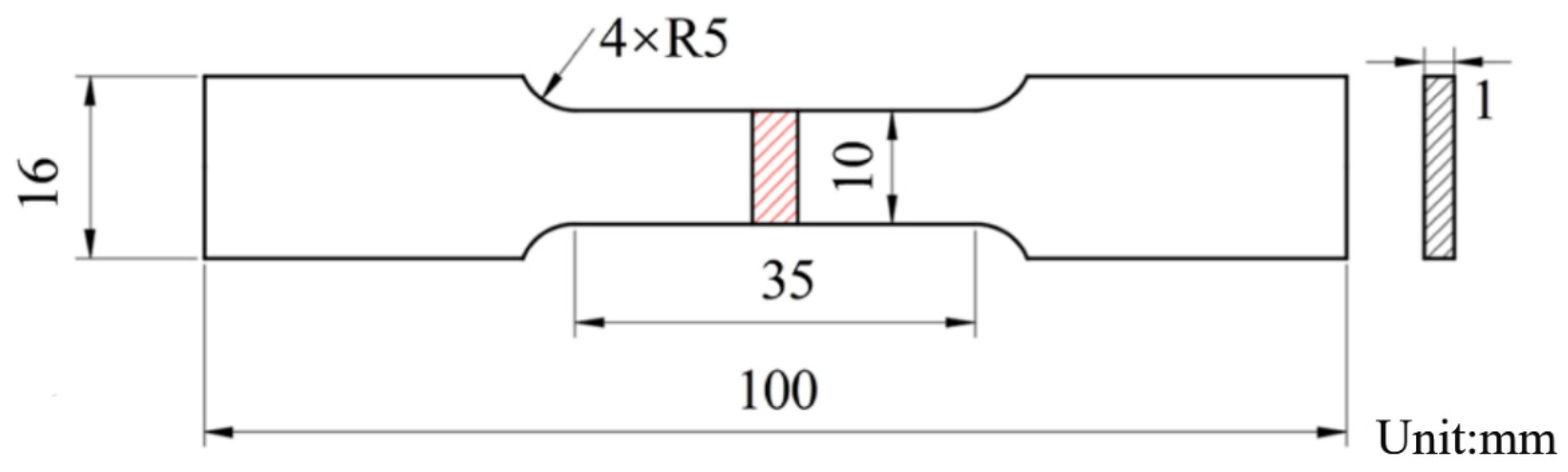
2.3. Microstructure and Mechanical Properties

The microstructure of the samples was observed using a Quanta 200 environmental scanning electron microscope (ESEM) (FEI). The conventional procedure was followed to prepare metallographic samples to study the properties of the longitudinal section of each individual melt channel. Aqua regia was chosen as the metallographic etchant and the etching time was approximately 30 s. The microstructure was observed using the Axiovert 200 MAT metallographic microscope.
The tensile samples were stretched at room temperature using a stretcher and the stretching rate was set to 0.01 mm/s, as shown in Figure 2.

3. Results and Discussion

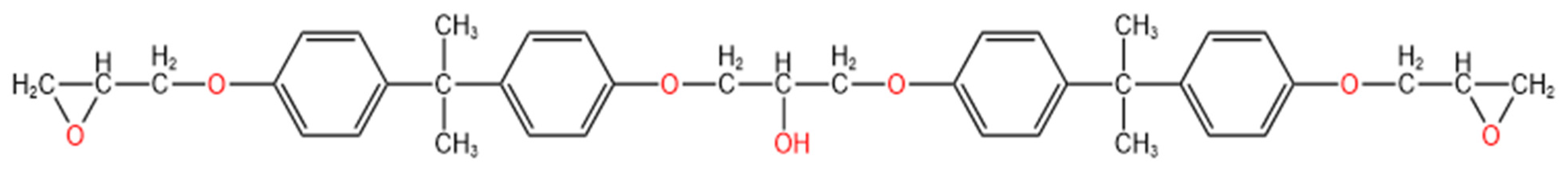
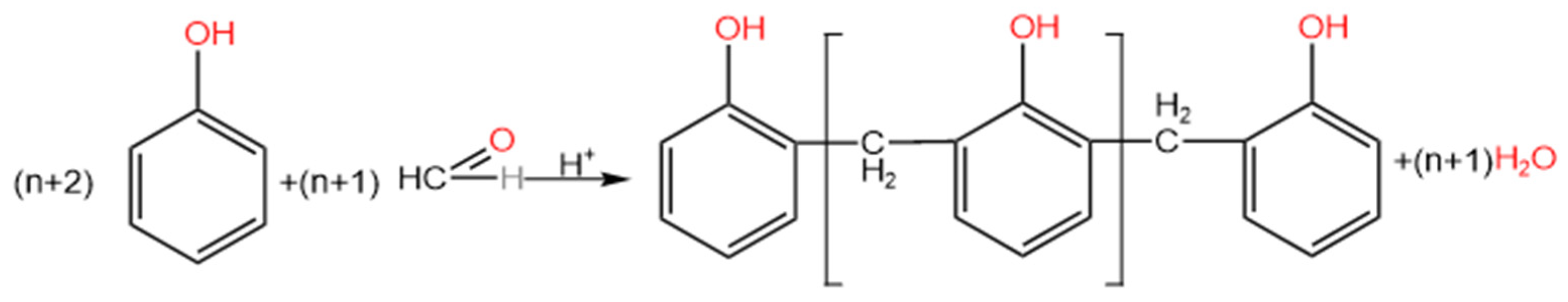
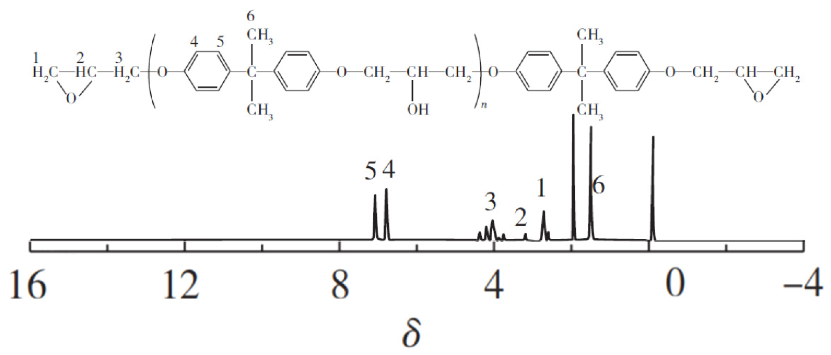
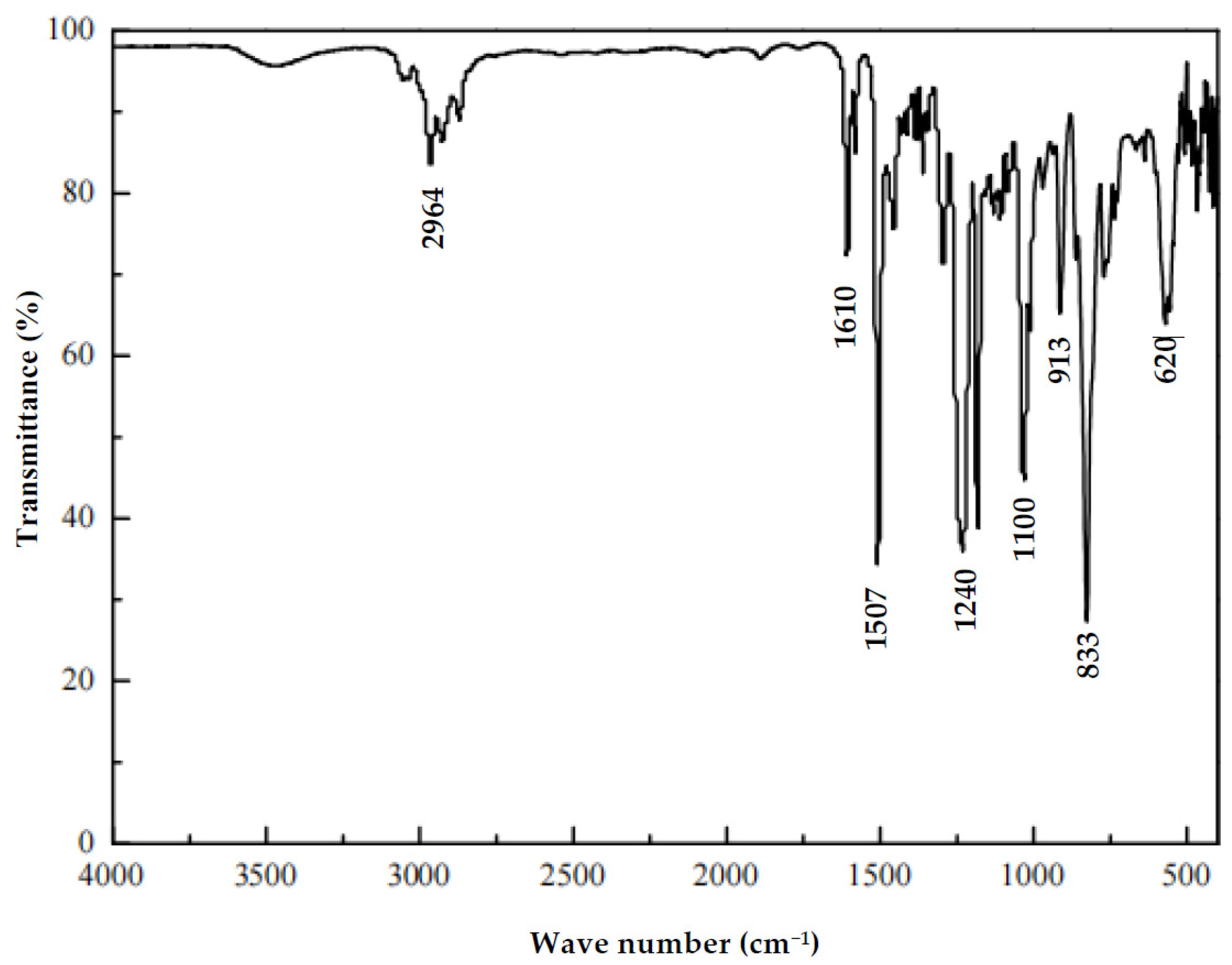
3.1. Characterization of Epoxy Resin

The FT-IR spectrum characterizes the molecular structure through the absorption of molecules to different wavelengths, so the infrared spectrum can well reflect the structural changes of epoxy resin before and after modification [31]. By observing the changes in peak type and peak area at the same position of the spectrum before and after modification, we can judge whether the epoxy resin is modified according to the ideal route.
The epoxy resin E-51 used in this experiment is the most representative bisphenol A diglycidyl ether, referred to as bisphenol A-type epoxy resin, and its FT-IR spectrum is shown in Figure 3. The characteristic absorption peaks of this epoxy group are 833 cm−1 and 913 cm−1. The stretching vibration absorption peak of C-O is in the range of 1300–1000 cm−1. The four absorption peaks at 1458, 1507, 1580, and 1601 cm−1 are the C-H characteristic absorption peaks of the benzene ring. C-H bending vibration occurs at around 1361 cm−1; the result of aliphatic C-H stretching vibration can be seen at around 2964 cm−1. There is a very wide absorption peak at 3492 cm−1, which is the main chain hydroxyl absorption peak. In addition, the 1H-NMR spectrum was also used to conduct nuclear magnetic analysis of the epoxy resin E-51, as shown in Figure 4, showing methylene at δ = 2.81; benzyl at δ = 3.12; methylene linked to O at δ = 4.05; the characteristic peak of the carbon of the benzene ring skeleton at δ = 6.53–7.18; and a tetrasubstituted carbon atom at δ = 1.55–2.06.

3.2. Preparation of Epoxy Resin Dispersion System

Because the viscosity of the epoxy resin is relatively high at room temperature, it is not easy to accurately prepare, so the epoxy resin is heated to a certain temperature to reduce its viscosity to a low enough level [32]. In this experiment, Novolac-type phenolic resin was produced through reaction with an acid as a catalyst when the molar ratio of phenol to formaldehyde was greater than 1. The reaction formula is shown in Figure 1. From Figure 1, it can be seen that phenolic resin has a large number of phenolic hydroxyl groups, which can improve its heat resistance when introduced into epoxy groups. Therefore, in this experiment, the Novolac phenolic resin was used as the prepolymer of epoxy resin, and epoxy resin and phenolic resin were, respectively, selected to prepare epoxy resin dispersion systems with four different mass ratios of 1:0, 2:1, 1:1, and 1:2, named the EP-0, EP2-1, EP1-1, and EP1-2 systems, respectively. The polymerization reaction of epoxy resin and phenolic resin can be preserved for several months without curing at room temperature without adding a curing agent, but after adding a curing agent, the curing reaction can be completely cured within 2 h at 160 °C.

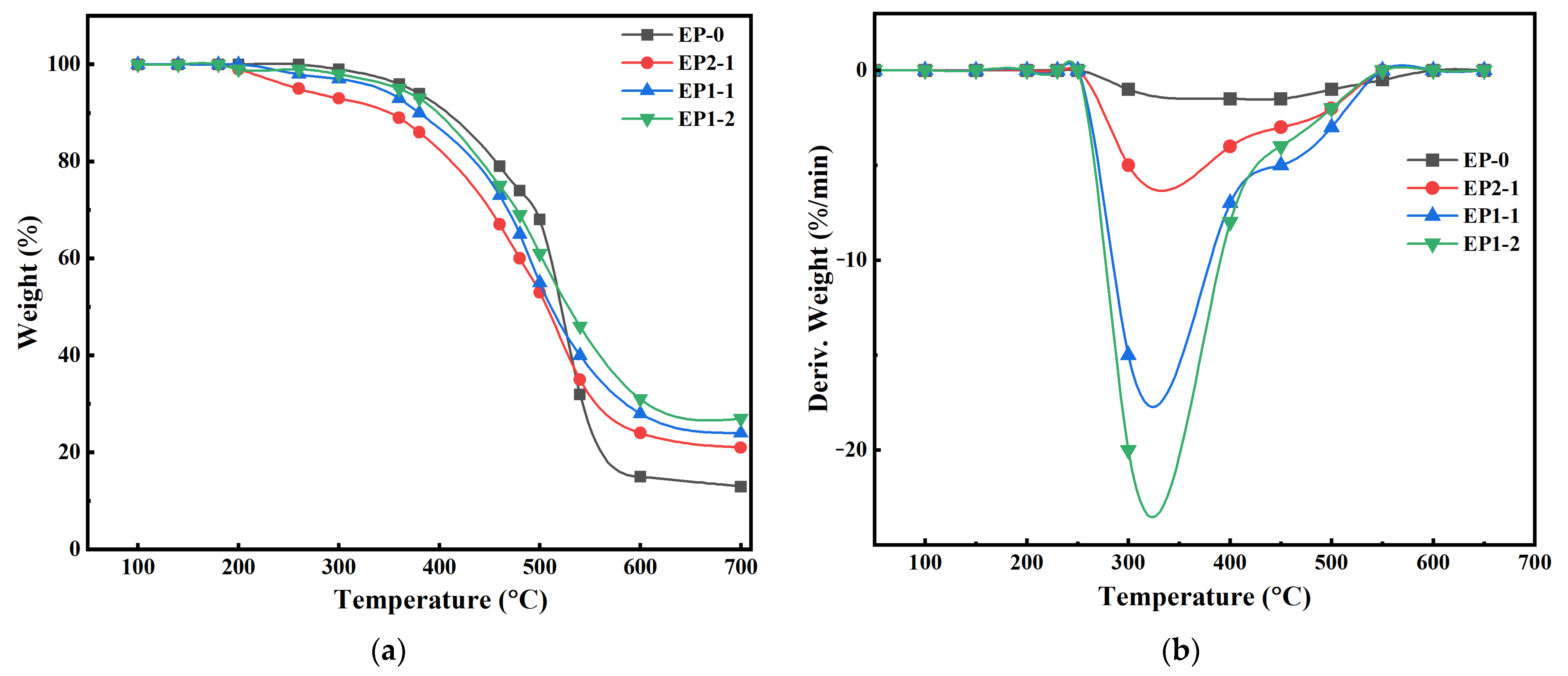
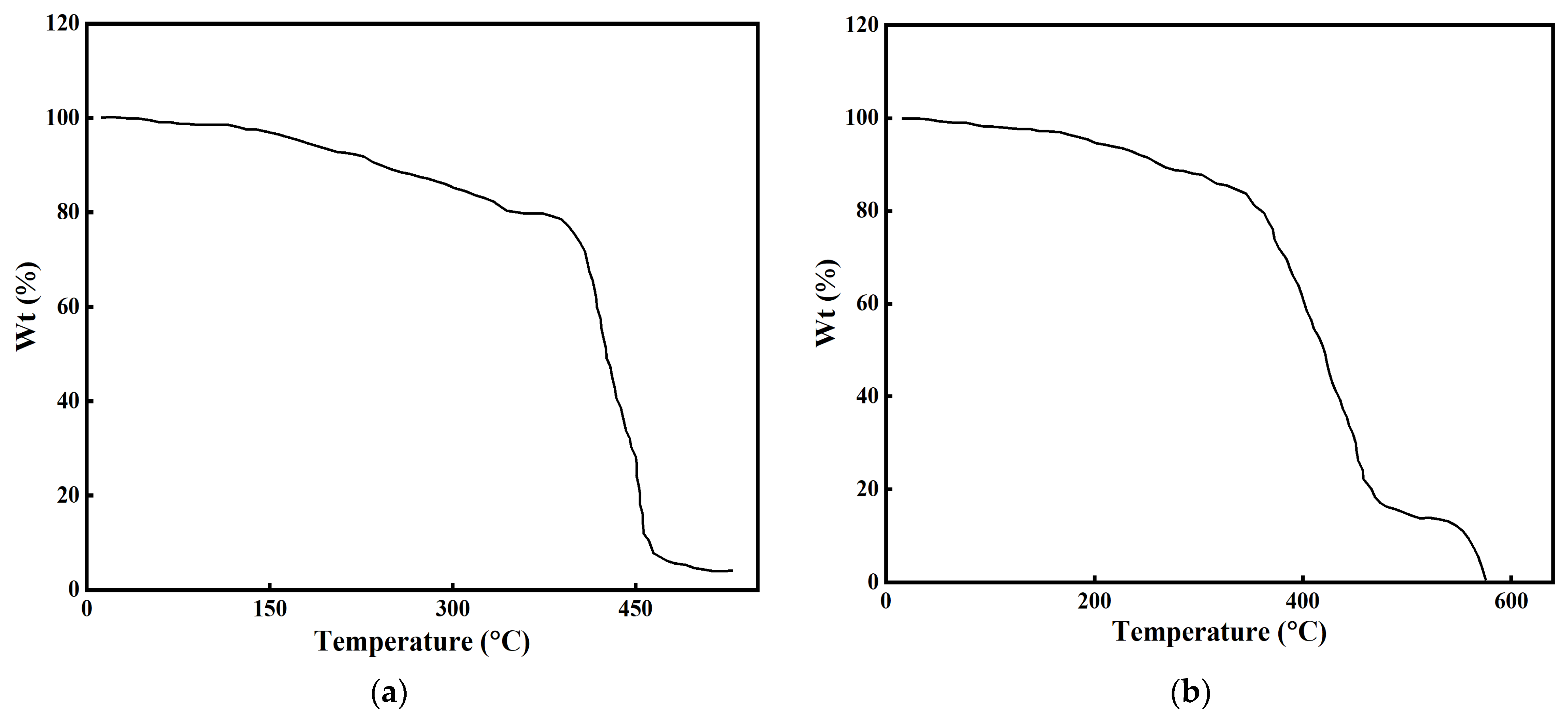
3.3. Thermal Properties of Cured Epoxy Resins

The thermal stability of the hybrids is shown in Figure 5. Several important parameters, including the glass transition temperature (Tg) and onset degradation temperature (Td) of the cured epoxy resins, the temperature of midpoint degradation (T50%), the temperature at the maximum weight-loss rate (Tmax), and char residue at 700 °C (R700), are summarized in Table 2.
The TGA curve in Figure 5a shows a one-step degradation trend. With the increase in temperature, under the nitrogen atmosphere, the Td and Tmax of the four cured epoxy resins showed a downward trend, especially EP2-1, which decreased by more than 100 °C, which was caused by the early degradation of S=P-C and P-O covalent bonds. In addition, steric hindrance caused by the bulky and hard hydroxy-benzene ring groups in phenolic resin reduces the cross-linking density of thermosetting [33]. When the phenolic resin reaches 50%, the Tmax was greater than EP-0. As can be seen from Figure 5b, the maximum weight-loss rates (Rmax) of EP0, EP2-1, EP1-1, and EP1-2 were 1.86%, 7.23%, 16.28%, and 24.56% min−1, respectively. Taking into account the Rmax value, the addition ratio of phenolic resin was more effective under the action of the curing agent, while the reduction in specific gravity of the epoxy resin alone was more significant than that of the other samples. Therefore, the addition of a curing agent can effectively reduce the thermal degradation rate in the low-temperature region. The epoxy resin retained only 12% of the carbon residue, as shown in Table 2. The carbon residues of EP2-1, EP1-1, and EP1-2 were 23%, 25%, and 28%, respectively. The presence of phenolic resin may contribute to the formation of carbon residues, thereby inhibiting the diffusion of oxygen atoms, reducing flammable volatiles, and inhibiting the melting of epoxy resin systems. Therefore, phenolic resin and curing agents are more efficient in the process of carbon formation. The thick carbon slag layer prevents further thermal degradation of the matrix and produces fewer flammable volatiles.

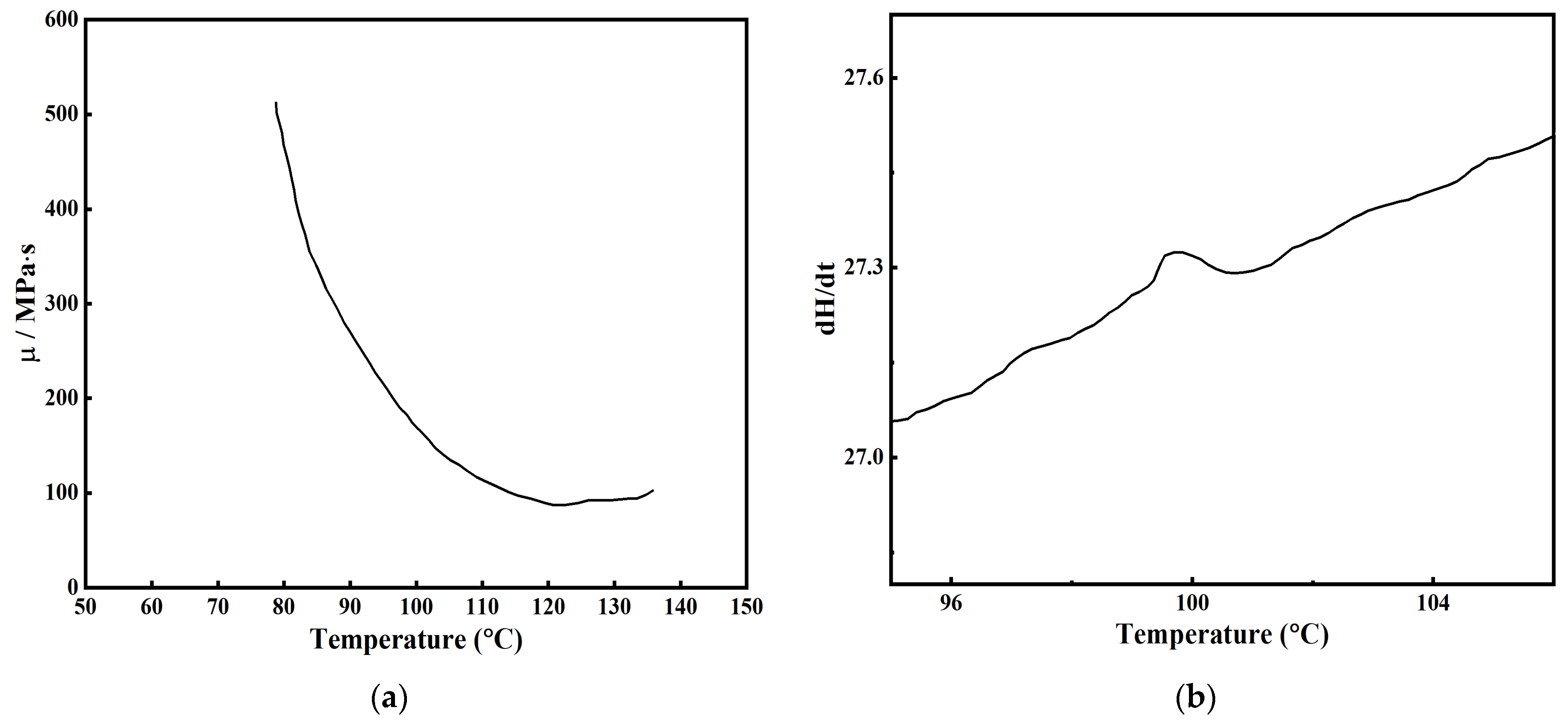
3.4. Infiltration Process of Epoxy Resin

The infiltration of resin is based on the infiltration theory of porous media. The resin is infiltrated into the pores of the medium through capillary force. When the viscosity of the resin is as low as possible at the right temperature, the metal parts are placed in the resin tank, so that the resin can be infiltrated into the pores of the metal parts as completely and quickly as possible. The resin can play the role of filling the pores and bonding the metal mesh in the medium [34].
To enable the epoxy resin system to quickly fill the porous metal sample, the viscosity of the fluid decreases as the temperature increases, which is conducive to wettability and fluidity. Firstly, the incubator was vacuumed and heated to 80 °C, and then the viscosity and curing temperature of the epoxy resin system were tested to determine the optimal infiltration temperature. The results are shown in Figure 6. Figure 6a shows that the viscosity of the resin system was the lowest at 120 °C, and the viscosity of the system began to rise when the temperature continued to rise, which is not conducive to the infiltration experiment. Then, the cured epoxy resin was analyzed through DSC. The ordinate of the DSC curve is the power difference dH/dt between the sample and the reference, also known as the heat flow rate, in milliwatts (mW). This value reflects the amount of heat absorbed by the sample relative to the reference at a certain time. As shown in Figure 6b, the infiltration agent had an exothermic peak at 101 °C, indicating that the curing reaction began at this time, and the viscosity increased when the temperature continued to rise to 140 °C, indicating that the degree of curing reaction was greater than the degree of viscosity reduction, so it was not appropriate to continue to rise. It can be concluded that infiltration should be carried out at a temperature of 100 °C.
According to the results of the above analysis and discussion, we gradually put the metal sample into the resin tank at 3 mm/min. Under the action of a vacuum, the resin will quickly and gradually infiltrate from the bottom of the blank to the top. When the upper surface becomes wet, it indicates that the resin is permeated, and the curing reaction is complete when the incubator is heated to 100 °C. The sample was then cooled to room temperature and taken out for a heat-resistant temperature test.

3.5. Heat Stability after Infiltration

Thermogravimetric analysis (TGA) was used to test the temperature resistance of the epoxy resin samples before and after infiltration. The result is shown in Figure 7. For the EP-0 system shown in Figure 7a, although the adhesion of epoxy resin was the strongest, the thermal stability was not high, at only about 300 °C. However, as can be seen from Figure 7b, the EP1-2 resin system did not decompose at 300 °C, and its thermal stability could reach 380 °C. Therefore, the EP1-2 resin was selected for impregnating the metal parts in order to meet conditions that require operating temperatures above 350 °C.

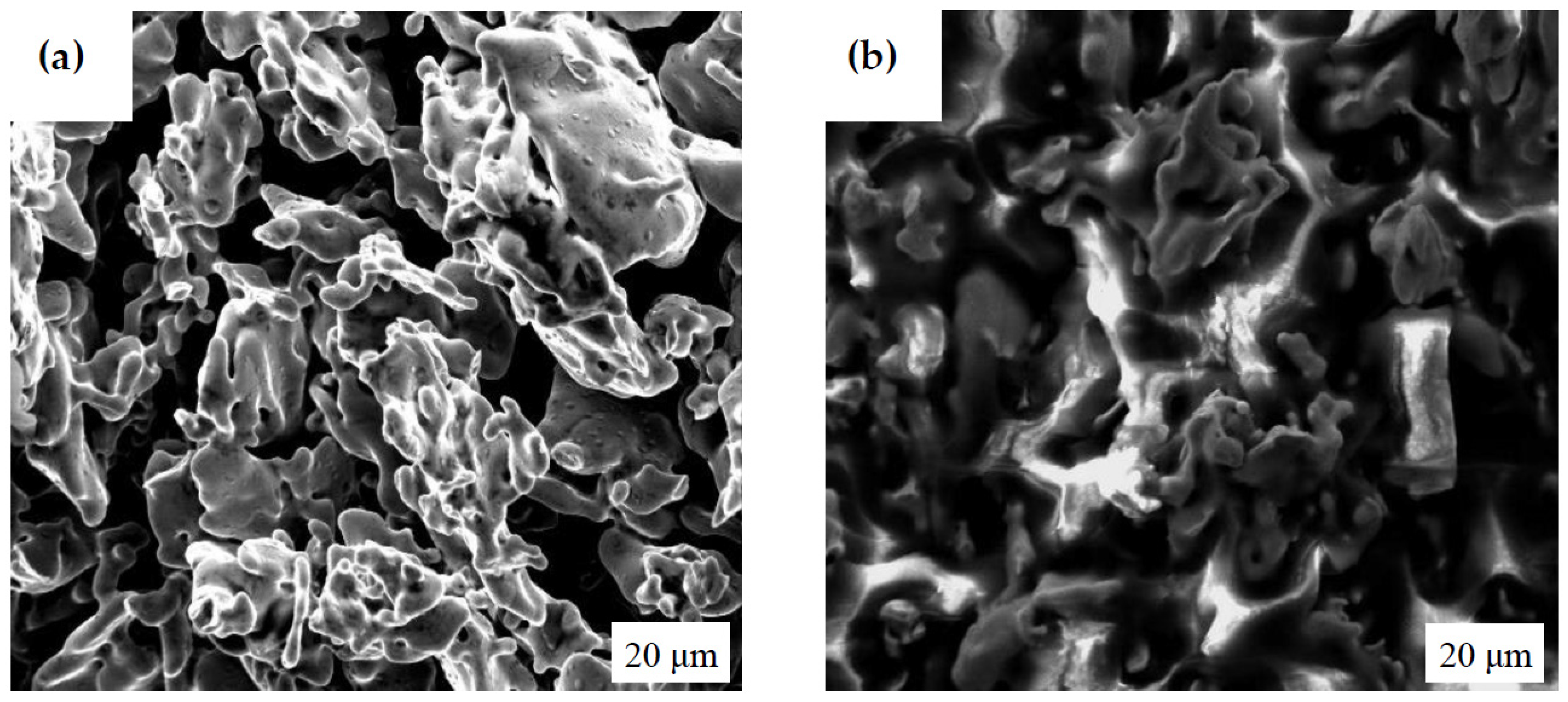
3.6. Microstructure after Infiltration

According to the research results in Section 3.5, it can be seen that the heat resistance temperature of the metal blank sample after resin infiltration was increased from 300 °C to 400 °C, and its thermal stability was significantly improved, so it can meet the application requirements of various environments. Scanning electron microscopy (SEM) was used to observe the microstructure of the tensile section before and after the impregnation of the sample, as shown in Figure 8. Figure 8a shows the SEM photo of the tensile section of the sintered part without resin infiltration. It can be seen from this figure that the dark color is the porosity of the sintered part, and the bright color is the bonding between the metal mesh frames. Although the metal mesh is fused and bonded, there are still pores between them, so the strength is very low. As can be seen from Figure 8b, the pores (dark part) have been filled by infiltrated epoxy resin (bright part), and the epoxy resin is closely bonded with the metal particle grid to form a dense network structure, so the strength is greatly improved. After sintering, the sample has a large number of pores and voids (Figure 8a), while after impregnation, a large number of pores of the sample have been filled with a permeating agent (Figure 8b). The filled resin mainly plays two roles in the blank.

3.7. Infiltration Theory of Porous Media

The structure of porous media is composed of solid matter and a substance, composed of a skeleton separated into large, dense groups of tiny voids. The fluid in porous media moves in the way of percolation, so the theory of studying the physico-mechanical properties of porous media involved in percolation mechanics becomes the basic component of percolation mechanics. The main physical characteristic of porous media is that the void size is extremely small and the specific surface area value is large. The tiny voids in the porous media may be interconnected or may be partially connected or partially disconnected. In this paper, after sintering metal powder parts formed with L-PBF technology, there are a large number of pores, and the pores are connected to form capillary tubes. Therefore, the porous media theory can be used for analysis. In this paper, an epoxy resin system is used as a permeating agent to infiltrate into the parts through capillary tubes. The height of the osmotic agent rising under the action of the capillary force is expressed by Formula (1) [35]:
h = 2 σ cos θ r ρ g
where h is the liquid surface rise height (m), r is the capillary radius (m), σ is the liquid surface tension (N/m), θ is the wetting angle (°), ρ is the density of the liquid (Kg/m3), and g is the acceleration of gravity (m/s2). When the temperature rise is not large, the surface tension of the liquid with the temperature change is not high, and can be regarded as a constant; at this time, the relationship of the viscosity of the osmotic agent with the temperature conforms to the Arrhenius formula, such as Equation (2) [36]:
η = A e Δ E k T
where η is the viscosity of the fluid (Pa·s), A is a constant (Pa·s), ΔE is the viscous flow activation energy (kJ/mol), k is Boltzmann’s constant (8.314 J/mol·K), and T is the thermodynamic temperature (K). It can be seen that the fluid viscosity decreases with increasing temperature, so the density of the liquid decreases. As the temperature increases, the activity of the osmotic agent increases, and the wetting of the metal grid is enhanced, so the wetting angle decreases. At the same time, while the viscosity decreases, the infiltration rate will also increase. For fluid infiltration in porous media, the infiltration rate can be described by Darcy’s theory, such as Equation (3) [37]:
Q = K A Δ P η S
where Q is the volume flow rate of fluid passing through a constant cross-sectional area (m3/s); K is the permeability coefficient of the resin (m2); A is the cross-sectional area of the sample (m2, perpendicular to the flow direction); ΔP is the corresponding pressure difference (Pa) of the flow length S; η is the resin viscosity (Pa·s); S is the distance of the flow front (mm). K reflects the osmotic properties of the fiber body. The permeability can represent the difficulty for fluid to flow through the porous medium of the fiber fabric, and the larger the value, the smaller the resistance to the resin flowing through the fiber bed.

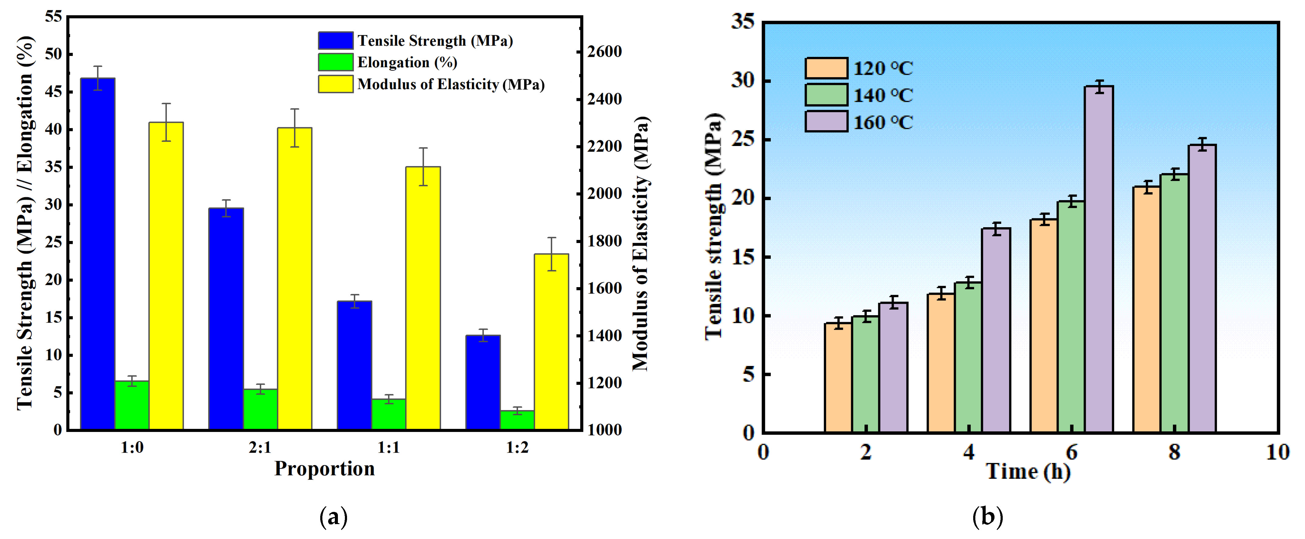
3.8. Analysis of Mechanical Properties after Infiltration

To obtain the best mechanical properties after infiltration, the samples of the four identified epoxy resin dispersion systems were tested for their mechanical properties. The results are shown in Figure 9. EP-0 was used for infiltration and the tensile strength was the highest, which was about six times higher than the original. When impregnated with EP2-1, the strength was second highest and increased by about four times. When impregnated with EP1-2, the strength was minimal, indicating that increasing the proportion of phenolic resin would affect the curing effect of the resin, and increasing the proportion of phenolic resin would lead to a decline in the performance of the sample. Then, the selected EP2-1 epoxy resin system was analyzed at different curing temperatures and curing times. The results showed that under the condition of curing at 160 °C for 6 h, the strength of the sample was the best, reaching 30 MPa, which was more than four times higher than that of the unimpregnated sample (7 MPa). However, serious carbonization was observed on the surface of the sample in the 180 °C curing test, indicating that the curing temperature was too high, and the mechanical properties of the sample did not improve significantly when curing for 2 h and 4 h, respectively. Therefore, the curing temperature of 160 °C and curing time of 6 h were adopted in this study to obtain the best mechanical properties.

4. Conclusions

In this paper, the feasibility of using bisphenol A epoxy resin to impregnate and strengthen the porous metal blanks of Fe-Cu-C metal powder formed through LPBF is studied. First, Novolac phenolic resin was used as the prepolymer of epoxy resin, and epoxy resin and phenolic resin were selected to prepare an epoxy resin dispersion system with four different mass ratios of 1:0, 2:1, 1:1, and 1:2, named the EP-0, EP2-1, EP1-1, and EP1-2 systems, respectively. Then, TGA and DTG analyses were performed for the synthesis of the four epoxy resins, followed by a discussion on the infiltration process, thermal stability analysis of the impregnated samples, and analysis of the observed structure of the impregnated blanks. Finally, the mechanical properties of the impregnated samples of the above four epoxy resin systems under different curing temperatures were analyzed. This study provides a feasible solution for the application of L-PBF to form model materials, biomaterials, and functional materials. The main conclusions of this paper are as follows:
  • The infrared and nuclear magnetic spectra of epoxy resin were analyzed, and the absorption peaks and characteristic peaks of each group and functional group were obtained. The temperature curves of TGA and DTG of EP-0, EP2-1, EP1-1, and EP1-2 epoxy resin dispersion systems were analyzed, and the decomposition temperature characteristics, carbon residues, and influencing factors of the different systems were obtained.
  • The changes in viscosity during the infiltration process were analyzed. The viscosity was the lowest at 120 °C, and it was found through DSC that the curing reaction had begun at 100 °C, which played a key role in the rotation of the optimal curing temperature. The thermal stability of the cured sample was analyzed, showing that the heat resistance temperature was increased from 300 °C to 400 °C, by nearly 100 °C.
  • Comparative analysis of the microstructures of the impregnated sample showed that the density was significantly increased and their structure was more dense. In addition, the mechanical properties of the EP-0, EP2-1, EP1-1, and EP1-2 epoxy resin dispersion systems were compared after infiltration, and the samples were tested after subjection to certain curing temperatures and curing times. The results showed that the curing temperature of EP2-1 was 160 °C and the curing time was 6 h.

Author Contributions

Conceptualization, J.C. and Y.S.; methodology, J.C.; software, Y.S.; validation, Y.S. and X.D.; formal analysis, X.D.; investigation, Y.L. and Y.Y.; resources, Y.L. and Y.Y.; data curation, J.C. and X.D.; writing—original draft, J.C. and Y.S.; writing—review and editing, Y.S.; visualization, Y.W. and J.Y.; supervision, Y.W. and J.Y.; project administration, Y.W. and J.C. All authors have read and agreed to the published version of the manuscript.

Funding

This paper was supported by the Science and Technology Project of the Science and Technology Department of Hubei Province (No. 2022EHB020).

Data Availability Statement

Data are contained within the article.

Conflicts of Interest

The authors declare no conflicts of interest.

References

  1. Monzon, M.D.; Paz, R.; Ortega, F.; Chapela, J.A.; Conde, C. Process for reinforcing SLS parts by epoxy resin. Rapid Prototyp. J. 2015, 21, 322–328. [Google Scholar] [CrossRef]
  2. Sow, M.; De Terris, T.; Castelnau, O.; Hamouche, Z.; Coste, F.; Fabbro, R.; Peyre, P. Influence of beam diameter on Laser Powder Bed Fusion (L-PBF) process. Addit. Manuf. 2020, 36, 101532. [Google Scholar] [CrossRef]
  3. Singh, R.; Gupta, A.; Tripathi, O.; Srivastava, S.; Singh, B.; Awasthi, A.; Rajput, S.; Sonia, P.; Singhal, P.; Saxena, K.K. Powder bed fusion process in additive manufacturing: An overview. Mater. Today Proc. 2020, 26, 3058–3070. [Google Scholar] [CrossRef]
  4. Wang, J.; Zhu, R.; Liu, Y.; Zhang, L. Understanding melt pool characteristics in laser powder bed fusion: An overview of single- and multi-track melt pools for process optimization. Adv. Powder Mater. 2023, 2, 100137. [Google Scholar] [CrossRef]
  5. Guo, A.; Wang, J.; Tang, R.; Kong, H.; Kong, D.; Qu, P.; Wang, S.; Wang, H.; Hu, Y. Insights into the effects of epoxy resin infiltration on powder aging issue induced by powder recycling in powder bed fusion of Nylon12 materials. J. Mater. Res. Technol. 2023, 23, 3151–3165. [Google Scholar] [CrossRef]
  6. Campbell, C.G.; Astorga, D.J.; Martinez, E.; Celina, M. Selective laser sintering (SLS)-printable thermosetting resins via controlled conversion. MRS Commun. 2021, 11, 173–178. [Google Scholar] [CrossRef]
  7. Liu, K.; Shi, Y.; Li, C.; Hao, L.; Liu, J.; Wei, Q. Indirect selective laser sintering of epoxy resin-Al2O3 ceramic powders combined with cold isostatic pressing. Ceram. Int. 2014, 40, 7099–7106. [Google Scholar] [CrossRef]
  8. Wang, D.; Liu, L.; Deng, G.; Deng, C.; Bai, Y.; Yang, Y.; Wu, W.; Chen, J.; Liu, Y.; Wang, Y.; et al. Recent progress on additive manufacturing of multi-material structures with laser powder bed fusion. Virtual Phys. Prototyp. 2022, 17, 329–365. [Google Scholar] [CrossRef]
  9. Shi, Y.; Chen, J.; Wang, Y.; Li, Z.; Huang, S. Study of the selective laser sintering of polycarbonate and postprocess for parts reinforcement. Proc. Inst. Mech. Eng. Part L J. Mater. Des. Appl. 2007, 221, 37–42. [Google Scholar] [CrossRef]
  10. Jin, L.; Zhang, K.; Xu, T.; Zeng, T.; Cheng, S. The fabrication and mechanical properties of SiC/SiC composites prepared by SLS combined with PIP. Ceram. Int. 2018, 44, 20992–20999. [Google Scholar] [CrossRef]
  11. Sutton, A.T.; Kriewall, C.S.; Leu, M.C.; Newkirk, J.W.J.V.; Prototyping, P. Powder characterisation techniques and effects of powder characteristics on part properties in powder-bed fusion processes. Virtual Phys. Prototyp. 2017, 12, 3–29. [Google Scholar] [CrossRef]
  12. Criales, L.E.; Arısoy, Y.M.; Lane, B.; Moylan, S.; Donmez, A.; Özel, T. Laser powder bed fusion of nickel alloy 625: Experimental investigations of effects of process parameters on melt pool size and shape with spatter analysis. Int. J. Mach. Tools Manuf. 2017, 121, 22–36. [Google Scholar] [CrossRef]
  13. Yan, C.; Shi, Y.; Yang, J.; Liu, J. Preparation and selective laser sintering of nylon-12 coated metal powders and post processing. J. Am. Acad. Dermatol. 2009, 209, 5785–5792. [Google Scholar] [CrossRef]
  14. Olakanmi, E.O.T.; Cochrane, R.F.; Dalgarno, K.W. A review on selective laser sintering/melting (SLS/SLM) of aluminium alloy powders: Processing, microstructure, and properties. Prog. Mater. Sci. 2015, 74, 401–477. [Google Scholar] [CrossRef]
  15. Khairallah, S.A.; Anderson, A.T.; Rubenchik, A.; King, W.E. Laser powder-bed fusion additive manufacturing: Physics of complex melt flow and formation mechanisms of pores, spatter, and denudation zones. Acta Mater. 2016, 108, 36–45. [Google Scholar] [CrossRef]
  16. Matthews, M.J.; Guss, G.; Khairallah, S.A.; Rubenchik, A.M.; Depond, P.J.; King, W.E. Denudation of metal powder layers in laser powder bed fusion processes. Acta Mater. 2016, 114, 33–42. [Google Scholar] [CrossRef]
  17. Gibson, I.; Rosen, D.; Stucker, B.; Khorasani, M. Powder bed fusion. In Additive Manufacturing Technologies; Springer: Cham, Switzerland, 2020; pp. 125–170. [Google Scholar]
  18. Snyder, J.C.; Thole, K.A. Understanding laser powder bed fusion surface roughness. J. Manuf. Sci. Eng. 2020, 142, 071003. [Google Scholar] [CrossRef]
  19. Hooper, P.A. Melt pool temperature and cooling rates in laser powder bed fusion. Addit. Manuf. 2018, 22, 548–559. [Google Scholar] [CrossRef]
  20. Levkulich, N.; Semiatin, S.; Gockel, J.; Middendorf, J.; DeWald, A.; Klingbeil, N. The effect of process parameters on residual stress evolution and distortion in the laser powder bed fusion of Ti-6Al-4V. Addit. Manuf. 2019, 28, 475–484. [Google Scholar] [CrossRef]
  21. Kusoglu, I.M.; Gökce, B.; Barcikowski, S. Research trends in laser powder bed fusion of Al alloys within the last decade. Addit. Manuf. 2020, 36, 101489. [Google Scholar] [CrossRef]
  22. Denlinger, E.R. Thermomechanical model development and in situ experimental validation of the Laser Powder-Bed Fusion process. Thermo-Mech. Model Addit. Manuf. 2017, 16, 215–227. [Google Scholar] [CrossRef]
  23. Cordova, L.; Bor, T.; de Smit, M.; Campos, M.; Tinga, T. Measuring the spreadability of pre-treated and moisturized powders for laser powder bed fusion. Addit. Manuf. 2020, 32, 101082. [Google Scholar] [CrossRef]
  24. Yin, J.; Wang, D.; Yang, L.; Wei, H.; Dong, P.; Ke, L.; Wang, G.; Zhu, H.; Zeng, X. Correlation between forming quality and spatter dynamics in laser powder bed fusion. Addit. Manuf. 2020, 31, 100958. [Google Scholar] [CrossRef]
  25. Young, Z.A.; Guo, Q.; Parab, N.D.; Zhao, C.; Qu, M.; Escano, L.I.; Fezzaa, K.; Everhart, W.; Sun, T.; Chen, L. Types of spatter and their features and formation mechanisms in laser powder bed fusion additive manufacturing process. Addit. Manuf. 2020, 36, 101438. [Google Scholar] [CrossRef]
  26. Narasimharaju, S.R.; Zeng, W.; See, T.L.; Zhu, Z.; Scott, P.; Jiang, X.; Lou, S. A comprehensive review on laser powder bed fusion of steels: Processing, microstructure, defects and control methods, mechanical properties, current challenges and future trends. J. Manuf. Process. 2022, 75, 375–414. [Google Scholar] [CrossRef]
  27. Paul, M.J.; Liu, Q.; Best, J.P.; Li, X.; Kruzic, J.J.; Ramamurty, U.; Gludovatz, B. Fracture resistance of AlSi10Mg fabricated by laser powder bed fusion. Acta Mater. 2021, 211, 116869. [Google Scholar] [CrossRef]
  28. Jibing, C.; Junsheng, C.; Junsheng, Y.; Yiping, W. Selective laser sintering of acrylonitrile butadiene styrene polymer and post-processing enhancement: An experimental study. Iran. Polym. J. 2023, 32, 1537–1550. [Google Scholar] [CrossRef]
  29. Khaing, M.; Fuh, J.; Lu, L. Direct metal laser sintering for rapid tooling: Processing and characterisation of EOS parts. J. Am. Acad. Dermatol. 2001, 113, 269–272. [Google Scholar] [CrossRef]
  30. Zhou, J.G.; Kokkengada, M.; He, Z.; Kim, Y.S.; A Tseng, A. Low temperature polymer infiltration for rapid tooling. Mater. Des. 2004, 25, 145–154. [Google Scholar] [CrossRef]
  31. Martin, A.A.; Calta, N.P.; Khairallah, S.A.; Wang, J.; Depond, P.J.; Fong, A.Y.; Thampy, V.; Guss, G.M.; Kiss, A.M.; Stone, K.H.; et al. Dynamics of pore formation during laser powder bed fusion additive manufacturing. Nat. Commun. 2019, 10, 1987. [Google Scholar] [CrossRef] [PubMed]
  32. Salmi, A.; Calignano, F.; Galati, M.; Atzeni, E. An integrated design methodology for components produced by laser powder bed fusion (L-PBF) process. Virtual Phys. Prototyp. 2018, 13, 191–202. [Google Scholar] [CrossRef]
  33. Masoomi, M.; Thompson, S.M.; Shamsaei, N. Laser powder bed fusion of Ti-6Al-4V parts: Thermal modeling and mechanical implications. Int. J. Mach. Tools Manuf. 2017, 118–119, 73–90. [Google Scholar] [CrossRef]
  34. Ahmed, N.; Barsoum, I.; Haidemenopoulos, G.; Abu Al-Rub, R. Process parameter selection and optimization of laser powder bed fusion for 316L stainless steel: A review. J. Manuf. Process. 2022, 75, 415–434. [Google Scholar] [CrossRef]
  35. Qu, S.; Ding, J.; Fu, J.; Fu, M.; Zhang, B.; Song, X. High-precision laser powder bed fusion processing of pure copper. Addit. Manuf. 2021, 48, 102417. [Google Scholar] [CrossRef]
  36. Jones, A.; Leary, M.; Bateman, S.; Easton, M. Effect of surface geometry on laser powder bed fusion defects. J. Am. Acad. Dermatol. 2021, 296, 117179. [Google Scholar] [CrossRef]
  37. Heigel, J.C.; Lane, B.M. Measurement of the melt pool length during single scan tracks in a commercial laser powder bed fusion process. J. Manuf. Sci. Eng. 2018, 140, 051012. [Google Scholar] [CrossRef]
Scheme 1. Molecular structure of bisphenol A epoxy resin.
Jcs 08 00099 sch001
Figure 1. Reaction formula of Novolac-type phenolic resin.
Jcs 08 00099 g001
Figure 2. Schematic diagram of tensile specimen.
Jcs 08 00099 g002
Figure 3. FT-IR spectrum of bisphenol A epoxy resin.
Jcs 08 00099 g003
Figure 4. 1H-NMR spectrum of bisphenol A epoxy resin.
Jcs 08 00099 g004
Figure 5. TGA (a) and DTG (b) curves of different ratios of epoxy resin in an N2 atmosphere.
Jcs 08 00099 g005
Figure 6. (a) Viscosity curve of epoxy resin; (b) DSC curve of curing reaction.
Jcs 08 00099 g006
Figure 7. (a) TGA curve of EP-0; (b) TGA curve of EP1-2.
Jcs 08 00099 g007
Figure 8. SEM photos of the cross section of the tensile specimen, (a) before and (b) after being infiltrated by epoxy resin.
Jcs 08 00099 g008
Figure 9. (a) Parameters of tensile properties of different resin-infiltrated systems; (b) tensile strength of specimens with different curing temperatures and times.
Jcs 08 00099 g009
Table 1. Performance parameter table for bisphenol A epoxy resin.
Performance ParameterValue
Softening point (°C)64~76
Epoxide number0.18~0.22
Epoxy equivalent450~525
Organochlorine content (%)≤0.02
Inorganic chlorine content (%)≤0.05
Average molecular weight850~1050
Volatility (110 °C, 3 h)≤1.0
AppearanceYellow to amber brittle solids
Table 2. Related TGA data for epoxy resin composites.
SampleTg
(°C)
Td
(°C)
T50%
(°C)
Tmax
(°C)
R700
(%)
EP-023037045250312
EP2-125536544849823
EP1-129437148648925
EP1-230537550248728
Disclaimer/Publisher’s Note: The statements, opinions and data contained in all publications are solely those of the individual author(s) and contributor(s) and not of MDPI and/or the editor(s). MDPI and/or the editor(s) disclaim responsibility for any injury to people or property resulting from any ideas, methods, instructions or products referred to in the content.

