Article

Finite Element Analysis of Cutting Temperature in Precision Cutting of Composite Energetic Material

1
Institute of Chemical Materials, China Academy of Engineering Physics, Mianyang 621999, China
2
Center for Precision Engineering, Harbin Institute of Technology, Harbin 150001, China
*
Authors to whom correspondence should be addressed.
J. Compos. Sci. 2024, 8(12), 525; https://doi.org/10.3390/jcs8120525
Submission received: 14 October 2024 / Revised: 19 November 2024 / Accepted: 3 December 2024 / Published: 13 December 2024
(This article belongs to the Section Composites Modelling and Characterization)

Abstract

:
While ensuring thermal safety is critically required in the operation of the composite energetic material, the cutting temperature is a crucial parameter that must be investigated and controlled in its cutting process to avoid thermal explosion. In this paper, we elucidate the mechanisms of heat generation and conduction during the cutting process of a composite energetic material by establishing a microstructure-based finite element (FE) simulation model considering thermal effects. Specifically, we simulated the cutting process of the composite energetic material by FE simulations, with a focus on the variations in the cutting force, the initiation and conduction of the cutting temperature, and the correlation of the damage behavior of the composite energetic material. Subsequently, we conducted a parametric investigation of the effect of cutting speed on the damage behavior and cutting response of the composite energetic material. This paper provides valuable insights for the exploration of the cutting processes of composite energetic materials.

1. Introduction

A composite energetic material is composed of a traditional energetic material combined with high-energy metals or non-metal materials, which has significantly improved volume energy density and mass energy density compared with traditional energetic materials [1]. For instance, Al powder is widely used in composite energetic materials due to its high energy density. Since the oxidation reaction of Al powder releases a large amount of heat, it has become an important way to improve the propulsion performance and ammunition damage power of composite energetic material by adding Al powders [2,3]. Composite energetic materials need to be machined into structural components to achieve their application in rocket propellant. As a highly particle-filled material, the composite energetic material has an extremely poor synergistic machining performance, due to the prominent differences in physical properties and the resulting cutting behavior between the constituent phases [4,5]. In addition, a large amount of cutting heat is produced due to the deformation of materials in the cutting process, which leads to a rapid increase in the cutting temperature that might easily cause ignition. Consequently, the cutting process of energetic material have great potential safety hazards. Furthermore, the cutting temperature has an important impact on the machined surface integrity and comprehensive performance of explosive components [6]. Therefore, it is essential to study the underlying cutting mechanisms of composite energetic materials, especially the evolution characteristics of cutting temperature during the cutting process.
In the metal-cutting process, high cutting temperature is the main cause of tool wear, which limits the improvement of productivity. In addition, the cutting temperature also reduces the machining accuracy, causing residual stress and other defects formed on the machined surface [7,8,9]. Similarly, the cutting temperature also plays a pivotal role in the machining process of composite energetic material. Since the composite energetic material contains potential energy that can be released as heat, light, sound, or destructive force if triggered, it is crucial to manage the heat generated during the machining process [4,10,11]. Tang et al. analyzed the underlying mechanisms of cutting heat accumulation in the ultrasonic vibration cutting process of composite energetic materials by characterizing the cutting temperature distribution on the machined surface and tool tip area [12]. Excessive heat can initiate a reaction in these materials, leading to potential harm [13]. Hence, effective heat management ensures the safety and effectiveness of machining operations of composite energetic materials, preserving the material properties and achieving the desired precision in the manufacturing process. Moreover, a well-controlled heat environment can significantly increase the longevity of cutting tools, ultimately contributing to highly efficient and cost-effective production cycles.
Finite element (FE) simulation has been widely employed to model and predict the temperature distribution in the cutting processes of different types of materials, as it helps to provide insights into the underlying mechanisms of material cutting, develop strategies to minimize excessive heat generation, and improve the efficiency and quality of machining operations [14]. Liu et al. studied the change law of the cutting temperature of energetic materials through 2D thermos–solid coupling FE simulation, and the results showed that the cutting temperature of explosives increases with an increase in the feed rate [15]. Yang and Zhu studied the cutting temperatures of the tool and workpiece during the milling process of Ti6Al4V through FE simulation [16]. Dandekar and Shin used 3D FE simulation to study the temperature distribution of particle-reinforced composite materials during the cutting process [17]. Bhagavat and Kao used FE simulation to study the heat-induced warping phenomenon of silicon wafers during the slicing process [18]. Moradi et al. used FE simulation to predict the incision depth of polycarbonate during the laser-cutting process [19]. Therefore, FE simulations have significant effectiveness in the temperature prediction during the machining processes of metals, ceramics, polymers, and composite materials.
In recent years, there has been a growing interest in studying the thermal effects during the shock process of energetic materials by FE simulations. Barua et al. studied the microscopic thermal response of energetic materials under impact loading through a cohesive finite element (CFE) framework. The results showed that the viscoelastic dissipation of the binder in energetic materials is the main reason for the formation of hot spots [20]. Miller et al. studied the shock-to-detonation process of energetic materials by constructing a mm scale 3D FE model. The results showed that the grain size, morphology, and size distribution in energetic materials have a significant impact on the detonation characteristics [21]. Duarte and Koslowski showed through FE simulation studies that the anisotropy of grains in energetic materials also has a significant impact on the formation of hot spots at different shock strengths [22]. Coffelt et al. used a 3D FE simulation model to show that the location of micro-voids in energetic materials has a significant impact on the temperature distribution under shock loading [23]. However, there is currently a lack of FE simulations on the cutting heat of energetic materials. More recently, Huang et al. showed through FE simulations that friction dissipation and viscous dissipation are the main components of internal energy dissipation in the cutting process of energetic materials [5]. However, there are currently no relevant reports on the microscopic temperature distribution and temperature change, as well as their dependence on cutting parameters, during the cutting process of composite energetic materials.
Therefore, in this paper, we develop a microscopic FE simulation model of the orthogonal cutting of a composite energetic material based on the CFE framework, considering the influence of the cutting temperature in the model. Specifically, the cutting mechanisms of composite energetic materials is investigated using the established FE simulation model, with a focus on the damage mechanisms and their correlations with the temperature distribution during the cutting process. Finally, the effect of cutting speed on the cutting process of composite energetic material is evaluated.

2. FE Modeling of Cutting of Composite Energetic Material

In this study, the established FE simulation model includes a workpiece and a cutting tool, as shown in Figure 1. The workpiece of composite energetic material consists of cyclotetramethylene tetranitramine (HMX) particles, Hydroxyl-terminated Polybutadiene (HTPB) binders and Al particles. The basic physical properties of the composite energetic material components and the cutting tool are listed in Table 1. The size of the workpiece is 1000 μm in length and 500 μm in height, and the size range of HMX particles is 50–100 μm with a volume fraction of 64.45%. The Al particle size is 5–10 μm with a volume fraction of 16.02%, and the volume fraction of HTPB binder is 19.53%. Firstly, the HMX particles and other regions are divided by using the Voronoi polygon region division method, and then the Al particles and the HTPB binders are divided by the Monte Carlo random algorithm. The cutting tool is set up as a discrete rigid body with a cutting edge radius of 0° and a rake angle of 10°. The left, bottom and right uncut parts of the workpiece are set as fixed constraints to simulate the full constraints of surrounding materials on the workpiece in the real cutting experiment. In order to study the influence of machining parameters on the cutting temperature of composite energetic material, multiple sets of cutting simulations are designed for research. Table 2 lists the cutting parameters used in this article [24,25]. In addition, the Coulomb friction model is employed to describe the tool–chip and tool–workpiece interactions, in which the frictional force is proportional to the normal contact force with the specified coefficient of friction as 0.5.
A CFE framework is used to simulate the damage and failure behavior of composite energetic material during the cutting process. This approach incorporates cohesive elements to simulate the initiation and evolution of damage based on the traction–separation law [5]. Cutting-induced debonding of the particle–binder interface and failure of the binder and explosive particles are represented by random crack generation and propagation in random directions of the cohesive elements. Table 3 lists the specific material parameters in the FE model that describe the tensile separation criterion of the cohesive elements [26,27]. Other material parameters and specific settings in the FE model of cutting of composite energetic material are consistent with those given in Section 2 of Ref. [5]. Unlike Ref. [5], this paper uses the Dynamic, Temp-dis, and Explicit analysis steps in the commercial software Abaqus 2021 to conduct the FE simulations, taking into account the temperature changes during the cutting process. In addition, the heat transfer between the tool and the workpiece is modeled by a thermal contact conductance approach, which considers the heat generated at the interface due to friction and plastic deformation. However, the heat transfer between the workpiece and the environment is neglected under the assumption that the cutting process occurs within a very short time, making the environmental heat exchange negligible.

3. Results and Discussion

3.1. Cutting Mechanisms of Composite Energetic Material

Figure 2 plots the variation of cutting force with cutting length in the cutting process of composite energetic material, which shows that the cutting force exceeds the thrust force significantly, and force variations occur consistently over a cutting length of 350 μm. Specifically, when the cutting starts, the cutting force rises sharply with tool feed, reaching a peak of 0.5 N, after which it fluctuates around a constant value of 1.1 N.
Figure 3a–i further present the stress contour map corresponding to the cutting length of 2.75 μm, 14.85 μm, 23.10 μm, 51.15 μm, 73.15 μm, 111.65 μm, 156.75 μm, 193.05 μm and 314.60 μm, respectively. As shown in Figure 3a, when the cutting tool initially contacts with the composite energetic materials, the HMX particles in direct contact with the tool edge show stress concentration and crack initiation along the tool edge. As shown in Figure 3b, with the feed of the cutting tool, the crack in the HMX particles gradually expands along the initial crack and eventually causes particle breakage. The fractured particles further compress the surrounding HTPB binder and Al particles, leading to stress concentration in the Al particles. As shown in Figure 3c, the chips gradually form with the continuous feed of the cutting tool; the HMX particles in the upper right corner of the workpiece interact with the rake face of the cutting tool, resulting in stress concentration and crack initiation at the contact points of the HMX particles. When the cutting length reaches 51.15 μm, as shown in Figure 3d, the HMX particles on the cutting path are directly cut off, while the HMX particles above the cutting path are extruded and broken into two pieces by the cutting tool and the part of the workpiece to be cut. With the further interaction between the cutting tool and the workpiece, the HMX particles under the cutting path are separated from the machined surface to cause surface pits and subsurface damage, and shear slip bands dominated by binder regions are formed inside the cutting chip, as shown in Figure 3e–h. When the cutting length reaches 314.6 μm, as shown in Figure 3i, the HMX particles near the rake face of the cutting tool are crushed, and some HMX particles at the subsurface and far away from the rake face of the cutting tool are crushed or removed by the common drawing action of the cutting tool and surrounding materials.
In order to validate the prediction results by the as-established FE model, typical chip profile and surface morphology from the reported experiments are selected for comparison [6,28]. As shown in Figure 4a, at a depth of cut of 0.3 mm, the chips of energetic materials exhibit wedge-shaped block removal, which is similar to the results shown in Figure 3d–i. As shown in Figure 4b, the brittle caving of explosive particles on the machined surface is obvious, which is mainly reflected by the fracture and spalling of explosive particles, similar to the results shown in Figure 3g–i. By comparing the results shown in Figure 3 and Figure 4, it can be inferred that the FE model established in this paper has high reliability in simulating chip profile and machined surface morphology of composite energetic materials.
Figure 5 plots variations of the highest temperatures of HMX, HTPB, and Al particles as a function of cutting length during the cutting process of composite energetic material. It is seen from Figure 5 that the cutting temperature produced in HMX particles is obviously higher than that in Al particles and HTPB binders. This can be attributed to the compression and fracture of HMX particles during the cutting process, which may promote friction and mechanical energy conversion to locally heat the HMX particles. At a cutting length of 250 μm, the maximum cutting temperature in HMX particles changes from the initial room temperature to nearly 200 °C; however, the cutting temperature of Al particles and HTPB binders remains between 20 °C and 30 °C. It is worth noting that the duration of FE simulation is short, and the cooling is not considered in the cutting process, which may lead to a high cutting temperature in the cutting process. By comparing Figure 2 and Figure 3, it can be found that the fluctuations in cutting temperature generally correspond to severe fluctuations in cutting force, but the cutting force fluctuations do not necessarily lead to the cutting temperature fluctuations, which may be attributed to the fact that the material deformation areas causing cutting force fluctuations do not coincide with the regions of existing high temperatures.
Figure 6 further shows the evolution of the distribution area with the highest temperature point with the cutting length. As shown in Figure 6a–c, the region of the highest temperature point corresponds to the initial position where the tool edge contacts with the workpiece. The maximum stress concentration in this region during the early stage of cutting is coupled with the thermoelastic fracture phenomenon during material fracture, which directly causes the temperature rise. As shown in Figure 6d, the maximum temperature point changes with the cutting length to the position where the rake face of the cutting tool and the chip contact with each other, for which the tool–chip friction and the thermoelastic fracture of HMX particles are the main factors for the temperature increase in the tool–chip interaction area. As shown in Figure 6e–g, the highest temperature point is transferred to the HMX particles at the upper part of the cutting edge, where increased internal stress and the thermoelastic fracture of the HMX particles become the main contributors to the rise in cutting temperature. With the feed of the cutting tool, the particles in the workpiece interact with each other. As shown in Figure 6h, the HMX particles below the tool edge are fractured due to the collision and extrusion caused by surrounding materials, resulting in stress concentration and material fracture. This ultimately causes a sharp temperature increase in the fractured region. When the cutting length reaches 314.6 μm, as shown in Figure 6i, the HMX particles in the cutting path are subjected to the shear action of the tool, and the material on the upper part of the HMX particles is crushed; thus, the cracks in the particles are transmitted into the whole particles, and the initial position of the cracks propagates into the area with the highest temperature. In conclusion, the stress concentration and the thermoelastic fracture of HMX particles are the primary causes of temperature rise during the cutting process of composite energetic materials.
The temperature value in the high-temperature region and its persistence time together determine whether the explosive material explodes or not. Figure 7 further shows the temperature changes of each high-temperature point in Figure 6 during the whole cutting process. It can be found from Figure 7 that the temperature in each area has experienced a process of first rising and then falling. Specifically, the rate of cutting temperature rise is significantly higher than the rate of cutting temperature decline, which shows that the reason for temperature rise is drastically changed. Combined with the analysis shown in Figure 6, it can be seen that thermoelastic fracture is the decisive factor of temperature rise.

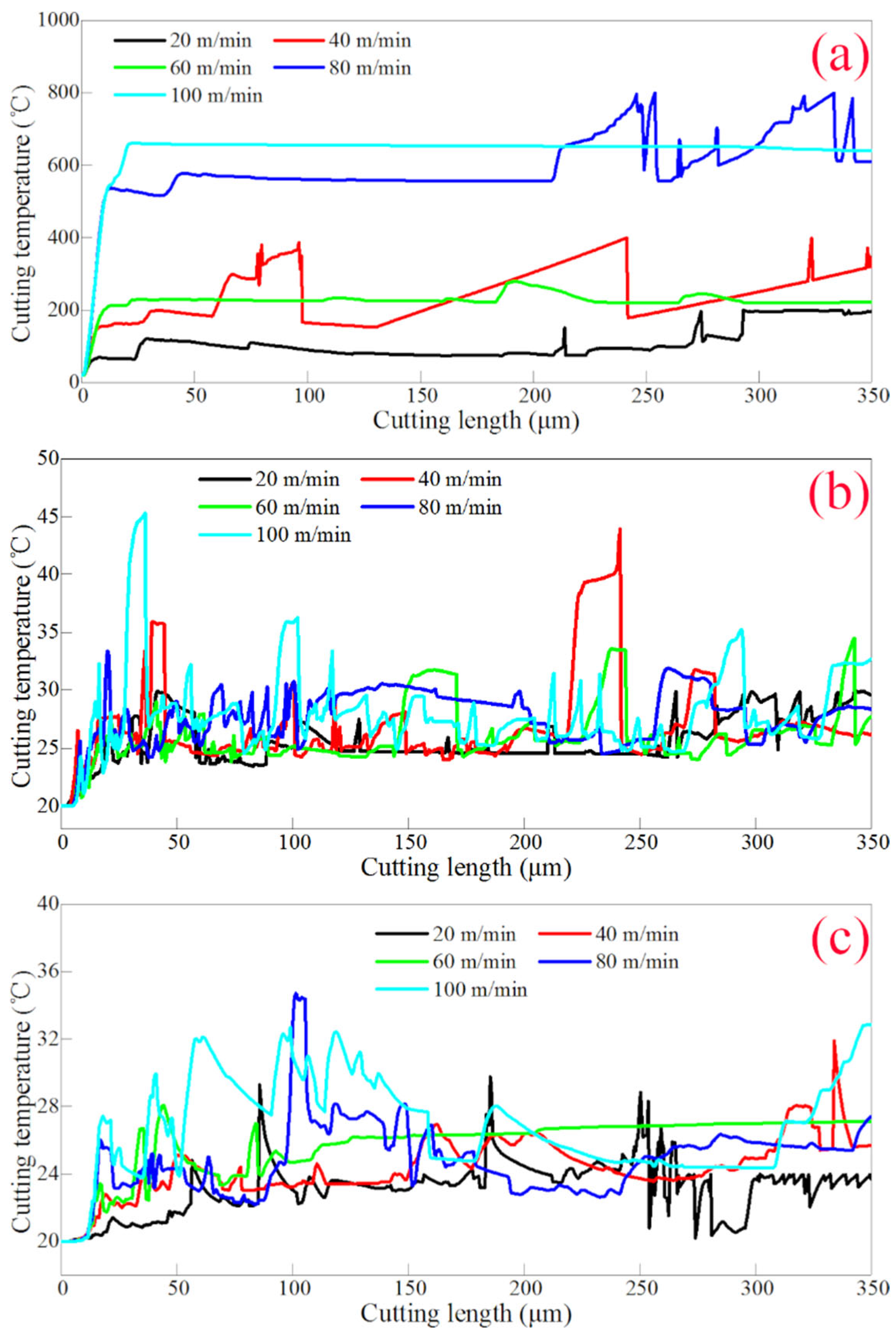
3.2. Influence of Cutting Speed on Cutting Temperature

Figure 8 depicts the variation of cutting force with cutting length at different cutting speeds. All cutting forces have a peak value around cutting lengths of 30 μm and 100 μm, and then fluctuate irregularly with the increase in cutting length. For the first cutting length of 50 μm, the cutting force increases with the cutting speed. When the cutting length is larger than 50 μm, the average cutting force increases with the cutting speed, but the real-time cutting force in some cutting lengths does not follow this rule. Specifically, for different cutting speeds, the material deformation and failure behavior of composite energetic material change, leading to further variations in the corresponding cutting forces.
In order to explain the influence of cutting speed on cutting results, Figure 9 shows the cutting results of composite energetic material at different cutting speeds at a cutting length of 340 μm. Obviously, with the increase in cutting speed, the relative movement speed between the cutting tool and the workpiece increases, leading to a rise in material strain rate and an increased degree of overall chip breakage. Specifically, according to the fluid mechanics resistance formula, with the increase in cutting speed, the deformation resistance of HTPB binder increases, the overall stiffness of workpiece material increases, and the damage of HMX particles on the machined surface intensifies, which jointly lead to the change of HMX particles from block fragmentation to powder fragmentation. In addition, with the increase in cutting speed, the deformation transfer time in the feed direction is shortened, resulting in a reduction in the length of material deformation in front of the cutting tool.
Figure 10 shows the change of the maximum cutting temperature with the increase in cutting length in different components of composite energetic materials. As shown in Figure 10a, the maximum cutting temperature in the HMX increases with the increase in cutting speed in the first cutting length of 50 μm. When the cutting length is larger than 50 μm, different cutting speeds do not necessarily correspond to higher maximum cutting temperatures. Specifically, the maximum cutting temperatures at the cutting speeds of 80 m/min and 100 m/min are significantly higher than the other cutting speeds, and the maximum cutting temperature at the cutting speed of 20 m/min is the minimum in the whole cutting length of 350 μm. Figure 10b,c illustrate the effect of cutting speed on the maximum cutting temperature in HTPB binders and Al particles of composite energetic materials. It can be seen from the Figure 10 that the maximum cutting temperatures in HTPB binders and Al particles both show irregular states with the increase in cutting speed. These results suggest that the deformation and failure of HMX particles are the primary factors influencing cutting temperature changes throughout the cutting process. In contrast, temperature variations in the HTPB binders and Al particles are mainly due to heat conduction from the HMX particles. According to the critical temperature of thermal explosion of HMX of 279.9 °C [29], a cutting speed of 20 m/min is a relatively safe processing parameter.
It is worth noting that the FE simulation in this paper is performed for a cutting distance of 350 μm, but the results provide valuable insights into the thermal and mechanical behavior of composite energetic materials during the initial stages of machining. These results are particularly important for understanding the local temperature distribution and its impact on material properties, which can guide the selection of optimal cutting parameters to ensure safety and efficiency in the machining of composite energy materials. In addition, while the research focused on a limited cutting length, theoretical analysis shows that the observed trends (such as the relationship between cutting speed and temperature rise) can be extrapolated to longer cutting distances under similar conditions. Beyond this initial distance, factors such as heat accumulation and tool wear may further influence the cutting process, presenting opportunities for future research. To address this issue, a potential solution is to implement intermittent cutting [30] or advanced cooling techniques [31] to mitigate heat buildup during extended machining operations.

4. Conclusions

In summary, in this study, we employ FE simulations to obtain fundamental insights into the temperature distribution and variation characteristics throughout the cutting process of a composite energetic material. The results of FE simulation indicate that the surface damage of the composite energetic material is mainly composed of the breakage and fracture of HMX particles, with HMX particles and Al particles detaching from the damaged binder. The deformation and failure of HMX particles are the main factors influencing cutting temperature changes. The fluctuation of cutting temperature often corresponds to the sharp fluctuations of cutting force, and the thermoelastic fracture of HMX particles during the fracture process is the decisive factor for the increase in cutting temperature inside the workpiece. With the increase in cutting speed, the degree of chip breakage and the average cutting force both increase. There is a strong correlation between cutting temperature and cutting speed in HMX particles. When the cutting speed difference is significant, higher cutting speed leads to higher cutting temperature. This methodology provides a novel approach for analyzing the thermal behavior of composite energetic materials under machining conditions, offering critical information for understanding the thermal effects on material properties and performance.

Author Contributions

Conceptualization, C.X. and J.Z.; methodology and software, J.L., S.L. and W.Z.; resources, J.L., C.X. and J.Z.; writing—original draft preparation, S.L.; writing—review and editing, C.X., S.L. and J.Z.; visualization, J.L. and S.L.; supervision, C.X. and J.Z.; project administration, J.L.; funding acquisition, J.L. All authors have read and agreed to the published version of the manuscript.

Funding

This research received no external funding.

Data Availability Statement

Data are contained within the article.

Conflicts of Interest

The authors declare no conflicts of interest.

References

  1. Altman, I. Burn time of metal nanoparticles. Materials 2019, 12, 1368. [Google Scholar] [CrossRef] [PubMed]
  2. Zapata, J.; Nicollet, A.; Julien, B.; Lahiner, G.; Esteve, A.; Rossi, C. Self-propagating combustion of sputter-deposited Al/CuO nanolaminates. Combust. Flame 2019, 205, 389–396. [Google Scholar] [CrossRef]
  3. Griego, C.; Yilmaz, N.; Atmanli, A. Analysis of aluminum particle combustion in a downward burning solid rocket propellant. Fuel 2019, 237, 405–412. [Google Scholar] [CrossRef]
  4. Yang, Z.; Kang, G.; Liu, R.; Chen, P. Predicting the mechanical behavior of highly particle-filled polymer composites using the nonlinear finite element method. Compos. Struct. 2022, 286, 115275. [Google Scholar] [CrossRef]
  5. Huang, J.; Lu, S.; Xie, F.; Liu, W.; Xiao, C.; Zhang, J.; Sun, T. Finite element analysis of synergetic deformation in precision cutting of polymer bonded explosive. Mater. Des. 2020, 188, 108471. [Google Scholar] [CrossRef]
  6. Xie, F.Y.; Zhang, Z.W.; Huang, J.H.; Liu, W.; Xiao, C.W. Cutting Force Response of Orthogonal Cutting of Polymer Bonded Explosive Simulants. Chin. J. Energetic Mater. 2019, 28, 151–156. [Google Scholar]
  7. Soori, M.; Asmael, M. Cutting temperatures in milling operations of difficult-to-cut materials. J. New Technol. Mater. 2021, 11, 47–56. [Google Scholar] [CrossRef]
  8. Özbek, O.; Saruhan, H. The effect of vibration and cutting zone temperature on surface roughness and tool wear in eco-friendly MQL turning of AISI D2. J. Mater. Res. Technol. 2020, 9, 2762–2772. [Google Scholar] [CrossRef]
  9. Sakkaki, M.; Moghanlou, F.S.; Vajdi, M.; Pishgar, F.; Shokouhimehr, M.; Asl, M.S. The effect of thermal contact resistance on the temperature distribution in a WC made cutting tool. Ceram. Int. 2019, 45, 22196–22202. [Google Scholar] [CrossRef]
  10. He, G.S.; Dai, Y.; Wang, P.; Zhang, C.Y.; Lin, C.M.; Yang, K.; Zhang, J.; Zhong, R.; Liu, S.; Yang, Z.J. Achieving superior thermal conductivity in polymerbonded explosives using a preconstructed 3D graphene framework. Energ. Mater. Front. 2023, 4, 202–212. [Google Scholar] [CrossRef]
  11. Akiki, M.; Gallagher, T.P.; Menon, S. Mechanistic approach for simulating hot-spot formations and detonation in polymer-bonded explosives. AIAA J. 2017, 55, 585–598. [Google Scholar] [CrossRef]
  12. Tang, W.; Zong, H.-H.; Wei, Z.-Y.; Huang, J.-H. Influence of ultrasonic vibration cutting on cutting temperature of explosive simulation material. Chin. J. Energ. Mater. 2014, 22, 71–74. [Google Scholar]
  13. Roeske, F.; Benterou, J.; Lee, R.; Roos, E. Cutting and machining energetic materials with a femtosecond laser. Propellants Explos. Pyrotech. Int. J. Deal. Sci. Technol. Asp. Energ. Mater. 2003, 28, 53–57. [Google Scholar] [CrossRef]
  14. Zhao, L.; Zhang, J.; Zhang, J.; Dai, H.; Hartmaier, A.; Sun, T. Numerical simulation of materials-oriented ultra-precision diamond cutting: Review and outlook. Int. J. Extrem. Manuf. 2023, 5, 022001. [Google Scholar] [CrossRef]
  15. Liu, R.P.; Jia, X.Z.; Wang, Y.S. Theoretical analysis and numerical simulation on influence factors of cutting temperature of explosive charge. Chin. J. Explos. Propellants 2018, 41, 484–488. [Google Scholar]
  16. Yang, Y.; Zhu, W. Study on cutting temperature during milling of titanium alloy based on FEM and experiment. Int. J. Adv. Manuf. Technol. 2014, 73, 1511–1521. [Google Scholar] [CrossRef]
  17. Dandekar, C.R.; Shin, Y.C. Multi-step 3-D finite element modeling of subsurface damage in machining particulate reinforced metal matrix composites. Compos. Part A Appl. Sci. Manuf. 2009, 40, 1231–1239. [Google Scholar] [CrossRef]
  18. Bhagavat, S.; Kao, I. A finite element analysis of temperature variation in silicon wafers during wiresaw slicing. Int. J. Mach. Tools Manuf. 2008, 48, 95–106. [Google Scholar] [CrossRef]
  19. Moradi, M.; Moghadam, M.K.; Shamsborhan, M.; Beiranvand, Z.M.; Rasouli, A.; Vahdati, M.; Bakhtiari, A.; Bodaghi, M. Simulation, statistical modeling, and optimization of CO2 laser cutting process of polycarbonate sheets. Optik 2021, 225, 164932. [Google Scholar] [CrossRef]
  20. Barua, A.; Zhou, M. A Lagrangian framework for analyzing microstructural level response of polymer-bonded explosives. Model. Simul. Mater. Sci. Eng. 2011, 19, 055001. [Google Scholar] [CrossRef]
  21. Miller, C.; Olsen, D.; Wei, Y.; Zhou, M. Three-dimensional microstructure-explicit and void-explicit mesoscale simulations of detonation of HMX at millimeter sample size scale. J. Appl. Phys. 2020, 127, 125105. [Google Scholar] [CrossRef]
  22. Duarte, C.A.; Koslowski, M. Hot-spots in polycrystalline β-tetramethylene tetranitramine (β-HMX): The role of plasticity and friction. J. Mech. Phys. Solids 2023, 171, 105157. [Google Scholar] [CrossRef]
  23. Coffelt, C.; Olsen, D.; Miller, C.; Zhou, M. Effect of void positioning on the detonation sensitivity of a heterogeneous energetic material. J. Appl. Phys. 2022, 131, 065101. [Google Scholar] [CrossRef]
  24. Walters, D.J.; Luscher, D.J.; Yeager, J.D.; Patterson, B.M. Cohesive finite element modeling of the delamination of HTPB binder and HMX crystals under tensile loading. Int. J. Mech. Sci. 2018, 140, 151–162. [Google Scholar] [CrossRef]
  25. Schwer, L.E.; Windsor, C.A. Aluminum plate perforation: A comparative case study using Lagrange with erosion, multi-material ALE, and smooth particle hydrodynamics. In Proceedings of the 7th European LS-DYNA Conference, Salzburg, Austria, 14–15 May 2009; p. 28. [Google Scholar]
  26. Roy, U.; Kim, S.; Miller, C.; Horie, Y.; Zhou, M. Computational study of ignition behavior and hotspot dynamics of a potential class of aluminized explosives. Model. Simul. Mater. Sci. Eng. 2018, 26, 085004. [Google Scholar] [CrossRef]
  27. Keyhani, A.; Kim, S.; Horie, Y.; Zhou, M. Energy dissipation in polymer-bonded explosives with various levels of constituent plasticity and internal friction. Comput. Mater. Sci. 2019, 159, 136–149. [Google Scholar] [CrossRef]
  28. Zhang, Q.; Huang, J.H.; Yin, R.; Tang, W. Micro-appearance and formation mechanisms of PBX cutting surface. Acta Armamentarii 2010, 31, 1337–1340. [Google Scholar]
  29. Tang, Z.; Yang, L.; Qiao, X.J.; Zhang, T.L.; Yu, W.F. On thermal decomposition kinetics and thermal safety of HMX. Chin. J. Energetic Mater. 2011, 19, 396–400. [Google Scholar]
  30. Ni, F.D.; Cong, W.L. Ultrasonic vibration-assisted (UV-A) manufacturing processes: State of the art and future perspectives. J. Manuf. Process. 2020, 51, 174–190. [Google Scholar]
  31. Kawade, P.; Bokade, S. Review of cooling techniques used in metal cutting processes. Adv. Mater. Process. Technol. 2022, 9, 1137–1182. [Google Scholar] [CrossRef]
Figure 1. FE model of cutting of composite energetic materials containing Al.
Jcs 08 00525 g001
Figure 2. Variation of machining force with cutting length in cutting process of composite energetic material.
Jcs 08 00525 g002
Figure 3. Cutting configuration of composite energetic material with a cutting length of (a) 2.75 μm, (b) 14.85 μm, (c) 23.10 μm, (d) 51.15 μm, (e) 73.15 μm, (f) 111.65 μm, (g) 156.75 μm, (h) 193.05 μm and (i) 314.60 μm.
Jcs 08 00525 g003
Figure 4. (a) Typical chip profile [4] and (b) machined surface morphology [28] in energetic material cutting experiments.
Jcs 08 00525 g004
Figure 5. Variation of maximum cutting temperature with cutting length in cutting of composite energetic material.
Jcs 08 00525 g005
Figure 6. Distribution of the highest temperature point in the workpiece when the cutting length is (a) 2.75 μm, (b) 14.85 μm, (c) 23.10 μm, (d) 51.15 μm, (e) 73.15 μm, (f) 111.65 μm, (g) 156.75 μm, (h) 193.05 μm and (i) 314.60 μm.
Jcs 08 00525 g006
Figure 7. Variation of the maximum temperature point at different cutting lengths with cutting length.
Jcs 08 00525 g007
Figure 8. Variation of cutting force with cutting length in cutting of composite energetic material under different cutting speeds.
Jcs 08 00525 g008
Figure 9. Cutting configuration of composite energetic material at a cutting length of 340 μm when the cutting speed is (a) 40 m/min, (b) 60 m/min, (c) 80 m/min and (d) 100 m/min.
Jcs 08 00525 g009
Figure 10. Variation of maximum cutting temperature of (a) HMX, (b) HTPB and (c) Al with cutting length in cutting of composite energetic material under different cutting speeds.
Jcs 08 00525 g010
Table 1. Basic physical properties of composite energetic material and cutting tool utilized in the FE model of cutting of composite energetic materials.
MaterialUnitHMXHTPBAlTool
Densityg/cm31.580.92.83.52
Young’s modulusMPa25,3520.7769,0001,147,000
Poisson’s ratio0.250.4990.330.07
Thermal conductivityW/(m·K)1931231932100
Specific heat capacityJ/(Kg·K)125415002000525
Table 2. Cutting parameters used in the FE simulations of cutting of composite energetic materials.
ParametersUnitValue
Cutting speedm/min20.0, 40.0, 60.0, 80.0, 100.0
Depth of cutμm200
Edge radiusμm0
Rake angle°10
Relief angle°5
Table 3. Parameters of cohesive elements applied to composite energetic composite.
Element PositionUnitInterior of HMXInterior of HTPBHMX-HTPB
Interface
Initial separation distanceμm0.050.010.0462
Critical tensile stressMPa10038.435
Destruction separationμm5104.62
Disclaimer/Publisher’s Note: The statements, opinions and data contained in all publications are solely those of the individual author(s) and contributor(s) and not of MDPI and/or the editor(s). MDPI and/or the editor(s) disclaim responsibility for any injury to people or property resulting from any ideas, methods, instructions or products referred to in the content.

