Article

Effect of Extreme Environments on Adhesive Joint Performance

VZLU–Czech Aerospace Research Centre, 19900 Prague, Czech Republic
*
Author to whom correspondence should be addressed.
J. Compos. Sci. 2024, 8(12), 511; https://doi.org/10.3390/jcs8120511
Submission received: 1 October 2024 / Revised: 27 November 2024 / Accepted: 2 December 2024 / Published: 6 December 2024
(This article belongs to the Section Polymer Composites)

Abstract

:
The presented research on adhesives was conducted with the aim of supporting the design of composite repairs for composite aircraft structures that can withstand specific environmental conditions. Double-sided strap joint specimens of epoxy-based CFRP adherents and straps were bonded by two types of adhesives. Room-temperature curing epoxy adhesives EC-9323 and EA-9395 were used for bonding. The specimens’ shear strength and failure modes were evaluated under four different environmental conditions from −72 °C up to 70 °C unconditioned and at 70 °C after humidity conditioning. The results show that EC-9323 performed excellently at room temperature, but very poorly at elevated temperatures after hot–wet conditioning. Adhesive EA-9395 performed consistently well across all tested conditions. The failure mode analysis explained the performance trends and the effect of the environment on the fractured surface. This study will support proper repair design and verification of numerical simulations. The novelty of this article lies in its combined analysis of multiple environmental factors, providing a more realistic assessment of joint performance.

1. Introduction

The presented research on adhesive joints was conducted to support the design of composite repairs for composite aircraft structures that can withstand specific environmental conditions. The main technology considered for repair applications is adhesive bonding of composite patches. Adhesives have been widely used in aircraft composite-bonded structures, which are required to maintain their performance under severe environment conditions involving high temperature and moisture during service. The selection of materials was driven by their suitable properties and commercial availability. The materials were selected based on an overview of the literature and previous experience.
Strength and fracture analyses of double-lap joints in carbon fibre polymer composites are a critical area of research, especially when these materials are tested in various environments. These composites are highly valued in industries where the strength-to-weight ratio is the dominant factor, such as aerospace [1,2]. The analysis of such joints involves understanding their mechanical performance under different conditions, which may include temperature variations, moisture exposure, and mechanical loading cycles. Studies have shown that adhesive bonding is the preferred method for creating lap joints in composite materials, as it provides an even distribution of stress across the joint, unlike bolted or riveted joints that can introduce stress concentrations. One of the joint types used for adhesive testing is the double-sided strap joint, which has the advantage of symmetrical loading without secondary bending, a phenomenon that is difficult to achieve in single-lap joints.
Adhesive bonding is also suitable for combination with mechanical joining techniques such as the use of rivets. So-called hybrid joining is used to improve the reliability of joints, whereby a rivet or a pin serves as a crack stopper to increase fatigue resistance [3,4]. Another benefit is the coupling effect of the adhesive and rivet that improves the strength due to changes in the failure mode [5].
During aircraft service, composite-bonded joints are required to withstand different weather conditions such as high temperature and moisture. Therefore, ensuring the durability of composite-bonded joints in severe environment conditions has become a big challenge in aerospace industries [6] and in oil and gas industries [7]. The effect of humidity conditioning has also been studied as adhesive degradation can be significant [8]. The process of humidity diffusion is much faster in the adhesive than in the composite, which makes the adhesive joints more sensitive to humid environments. Moisture interacts with the adhesive by penetrating the adhesive’s voids via capillary action or by reacting with hydrophilic functional groups; this can affect the interfacial region by causing swelling, plasticization, and in irreversible cases, chain degradation [9].
In addition, increasing the thickness of the adhesive layer contributes to greater moisture sorption, as seen in the diffusivity coefficient values, where thicker samples sorbed water faster than thinner samples [7]. The degradation of the mechanical properties of joints can also be reflected in the failure mode [10].
The effect of hygrothermal ageing was also observed for hybrid joints, whereby the change in temperature mainly affected the strength of the joint and had little effect on the displacement corresponding to the fracture. However, as the degree of humidity aging increased, the displacement corresponding to the fracture increased significantly [11].
Reference [12] observed the deterioration of epoxy adhesive joints when exposed to a saline environment. Characterization under static loading in mode II conditions revealed a notable reduction in the maximum displacement as exposure time to the saline environment increased, with longer exposure periods making the adhesive more brittle. Another study [13] showed the effect of saline environment corrosion on the fatigue life of double-lap shear adhesive joints, where the fatigue life decreased by 90%.
The effect of low temperature depends on the humidity state of the joint. Ref. [14] studied polyurethane adhesives used on butt joints with a combined shear load. The failure load of the humidity-aged specimen significantly decreased due to low temperature compared to its dry state. However, the cold environment increased the strength of the dry joint. Similar behaviour was observed in Ref. [15] for epoxy adhesives Bondex606, EA-9696, and FM73, where the joint’s performance increased by 50% at −150 °C. The actual failure mode was a combination of adhesive and delamination failure.
Plasma surface treatment has been utilized in the treatment of various polymer-based materials to correlate the surface morphology and mechanical properties. The superior performance of plasma treatment was also observed for environmentally aged specimens [16]. The results of this work revealed the great impact of plasma treatment on the long-term durability of GFRP/adhesive joints, especially when exposed to harsh environments such as offshore wind turbines.
Furthermore, elevated temperatures can cause chemical and physical changes in the adhesive, such as softening, a loss of stiffness, and reduced shear strength. These changes compromise the adhesive’s ability to transfer loads effectively between the CFRP and the substrate [17,18]. The glass transition presents “softening” of the adhesive as it changes from a glassy to a rubbery state, but this does not occur at a single temperature, and the stiffness and strength of the adhesive may decrease considerably before Tg is reached [19]. High temperatures greatly decrease the interfacial strength of polymer matrix composites at temperatures above the resin’s Tg. On the other hand, cryogenic temperatures create micro-cracks between the fibre and polymer matrix [20]. Ref. [7] also showed that the thickness of the adhesive does not affect the drop in Tg of an epoxy-based adhesive.
Failure mode codification was established by the standard ASTM D5573 [21], which covers the method of classifying, identifying, and characterizing the failure modes in adhesively bonded fibre-reinforced plastic joints. A study described the fracture morphologies of different combinations of materials [22], showing that interfacial debonding was the most frequent cause of failure. There are also uncertainties such as kissing bonds, porosity, and voids in adhesives that limit the potential of adhesive joints [23].
Finite element analysis also offers many possibilities for analyzing joints [24]. The elasto-plastic stress–strain behaviour of both the adhesive and the adherends can be simulated. The main limitation of this numerical approach lies in selecting the correct failure criterion [25], which depends on the failure mechanisms investigated in the report. The objective of this article is to experimentally evaluate the impact of temperature on the shear strength and failure mechanisms of joints, which is critical for many structural applications. The unique aspect of this article is the evaluation of long-term hot–wet environmental effects on joint strength and failure mode. This extreme environment proved to dramatically affect the performance of a joint bonded by a high-strength epoxy adhesive with excellent room-temperature properties. By understanding how different factors affect joint performance, engineers can optimize joint design for better durability and reliability. The novelty of this article lies in its comprehensive approach; by performing a combined analysis of high-temperature and wet environmental effects, this study provides a more realistic assessment of joint performance.

2. Materials and Methods

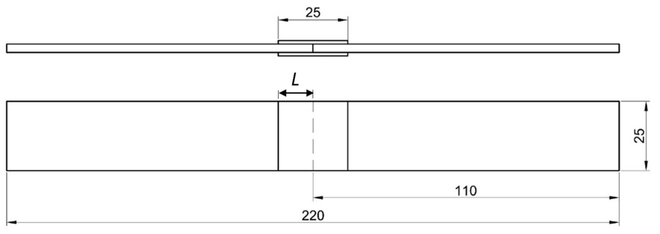
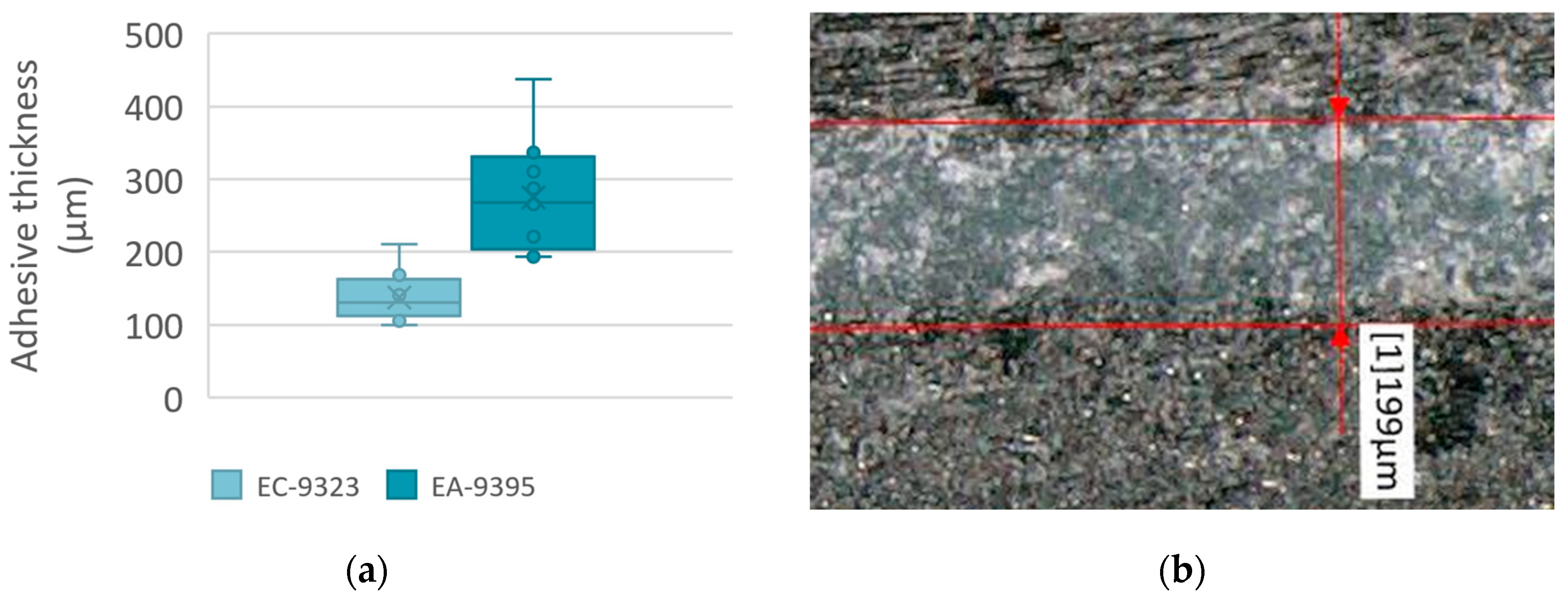
2.1. Specimen Manufacturing

Double-lap joint specimens of type B were manufactured based on the ASTM D3528 standard [26]. Figure 1 shows the geometry of two adherents joined by two straps.
The adherents are made of carbon fibre-reinforced polymer manufactured from HexPly 8552 resin reinforced by AS4 12K Polyacrylonitrile (PAN) carbon fibres and cured according to the supplier’s recommendation. The laminate is made of 16 plies with stacking sequences of [45, −45, 0, 45, 45, −45, −45, 90]s (nominal thickness of 3 mm).
The straps (patches) are made of carbon fibre-reinforced polymer manufactured from Loctite EA-9396 resin reinforced by ECC 450-5 Aero carbon fibres and cured at room temperature for 24 h, with additional curing at 66 °C for 1 h. The laminate is made of 6 plies with stacking sequences of [0]6 (nominal thickness of 1.5 mm).
The material properties of both the adherent and the strap are stated in Table 1.
Before bonding, a peel ply was removed from the straps, and abrasive paper #100 and isopropyl alcohol were used to grind and clean the strap bonding surface. A peel ply is a sacrificial layer that is applied to the surface of the composite before curing. However, the matrix resin interacts with the peel ply, and the peel ply residue affects joint strength [27]. Therefore, Diatex 1500V6 peel ply, which is recommended for critical secondary structural bonding, was used. There is no release agent or silicon in the fabric. The surface was modified via sanding treatment to remove weak boundary layers and contaminants [16]. The adherents were grit-blasted by white corundum sand F 120 and cleaned by using isopropyl alcohol before bonding. Then, the materials were split into two sets and bonded together, each with a different adhesive. For the set with Scotch-Weld EC-9323 B/A, the plates were cured for 24 h at room temperature and 2 h at 66 °C. The other set was bonded with Loctite EA-9395, and the plates were cured for 24 h at room temperature and 1 h at 66 °C. Finally, 12 similar specimens were cut from each plate using a diamond blade with subsequent edge milling. The details of the joint edges are depicted in Figure 2.
The thickness of the adhesive layer in laminate bonding is a critical factor that influences the overall strength and performance of the bonded structure. Research indicates that the bond strength of a joint with a thinner adhesive is more sensitive to the surface topography [28]. On the other hand, increasing bond-line thickness proportionally increases the probability of having internal defects [23].
Figure 3 presents adhesive layer thickness measurements for both adhesives. There was a significant difference in both the mean values and the variation in thickness. The average values were 138 μm and 275 μm for EC-9323 and EA-9395, respectively. The second adhesive also had greater thickness variation among the specimens.

2.2. Test Procedures

The test matrix in Table 2 describes the specific temperatures at which the joint specimens were tested. Three sets of specimens were unconditioned and tested at −72 °C, 21 °C and 70 °C and one set was tested at 70 °C after wet conditioning.
Conditioning of the specimens in the wet environment was conducted according to ASTM D5229M, procedure BHFF [29]. It covers a fixed time in a humid environment of 70 °C/85% r.h. (±3 °C, ±3% r.h.). The time was set to at least 1000 h as the adhesive should conservatively reach the equilibrium state of weight gain in this period. The adherent needs more time to reach equilibrium; however, it is not relevant for this joint test as the adhesive determines the strength. The environment was monitored over the entire duration of 1000 h. At the end of the interval and on the day of mechanical testing, the specimens were removed from the chamber and final weighing was performed. The specimens were stored in a sealed bag before testing.
The mechanical test procedure was based on ASTM D3528M [26]. The setup included flexible tension coupling. The specimen was placed between grips with a grip contact length of 32 mm. For non-room temperatures, a thermocouple was affixed to the surface of the specimens. After reaching the required temperature followed by 3 min of wait time, loading at a rate of 1.27 mm/min up to failure started. From the shear stress–displacement curve, we evaluated the maximum ultimate shear strength τ = Fmax/2WL, where Fmax is the maximum load, W is the specimen width, and L is the length overlap (see Figure 1).
Post-test fractographic analyses were performed as follows. Selected specimens were cut with a diamond-coated saw. Compressed air was used to remove saw debris from the surface. Each specimen was then mounted on a pin stub using a double-sided adhesive target and coated with an 8–12 nm thick Au/Pd layer using a sputter coater. Microfractographic analysis of the fracture surfaces was performed using a VEGA 3SBU scanning electron microscope (SEM) from TESCAN manufacturer based in Brno, Czech Republic. It was set to secondary electron imaging mode. High-vacuum mode with a voltage of 20 kV was used for evaluation. The microscopy parameters set for each image are noted below the images. Vega TC (TESCAN) microscope operation software was used.

3. Results and Discussion
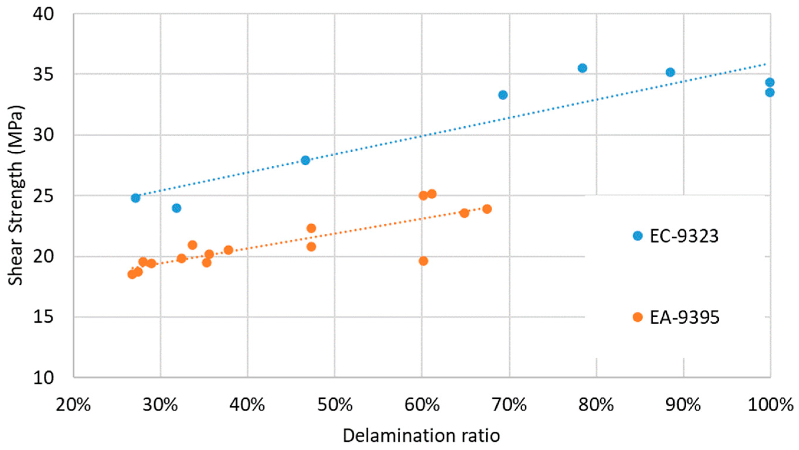
3.1. Shear Strength

Average shear strength values were evaluated for six specimens tested in the defined environments. The overall graphical presentation is visible in Figure 4. The results for EC-9323 showed a peak performance of 34.5 MPa at 21 °C (Table 2). The lowest value of 6.2 MPa was measured at 70 °C after wet conditioning. The heavily reduced strength was most probably caused by reaching Tg earlier as a result of wet conditioning. Table 3 presents the observed failure modes analyzed in Section 3.2.
A similar trend was shown in Ref. [30] for double-lap shear tests of an epoxy adhesive, whereby the failure load decreased significantly (decreased by 25%) after immersion in 95 °C water. However, strength decreases at low temperatures were not the case in Reference [15], in which tests were performed on three different epoxy adhesives. Another study [31] showed a decrease in strength at −30 °C compared to at room temperature for Loctite ESP110, Araldite 2015, and AV138 adhesives. Overall, the joint strength at low temperatures is limited by the adherent’s interlaminar properties, as the delamination failure mode is more prevalent.
The results for EA-9395 showed a peak performance of 24.2 MPa at 70 °C (Table 4). The lowest value of 18.3 MPa was measured at 70 °C after wet conditioning. Overall, the values were very consistent among the environments, even for the wet state. This can also relate to Tg because it is 119 °C for the wet state and 73 °C for the dry state [32]. Figure 4 presents the shear strength results as a bar plot, including the samples’ standard deviations.

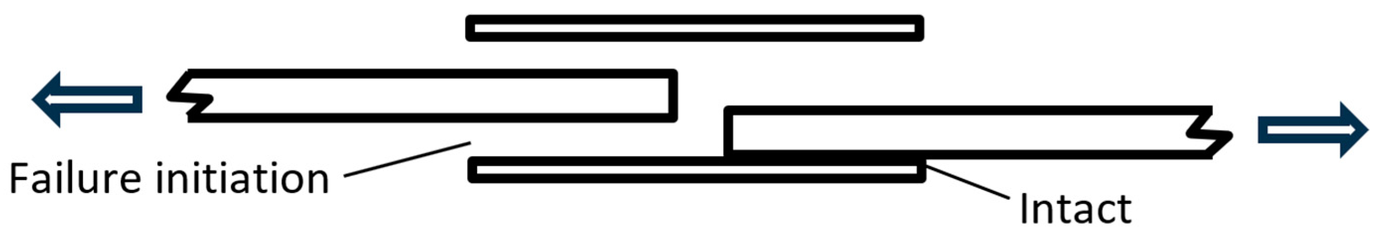
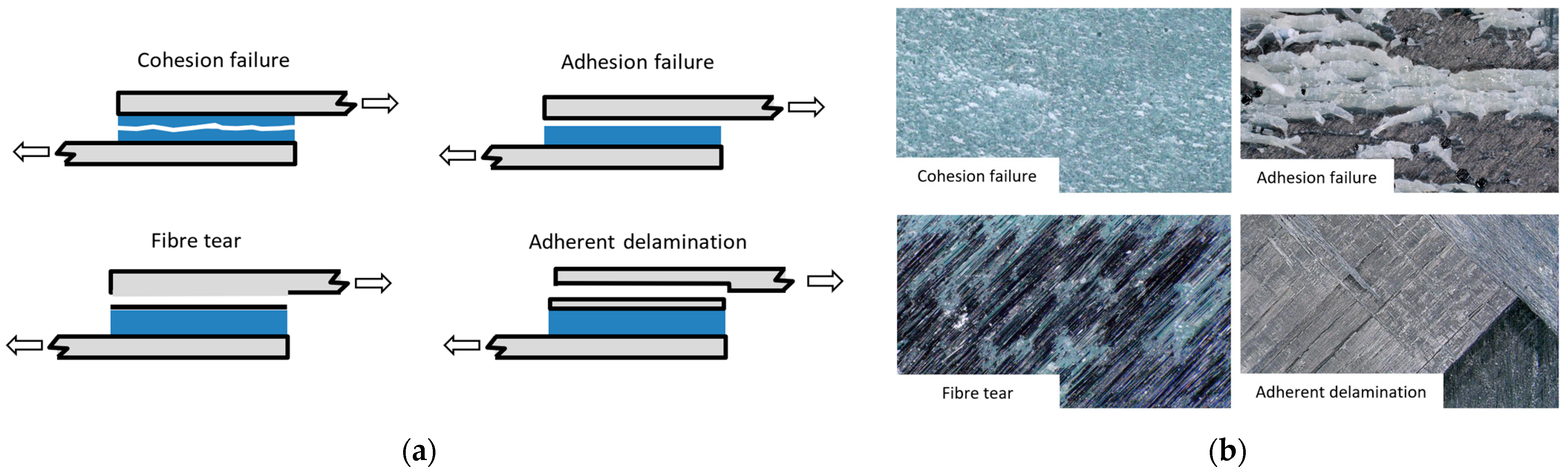
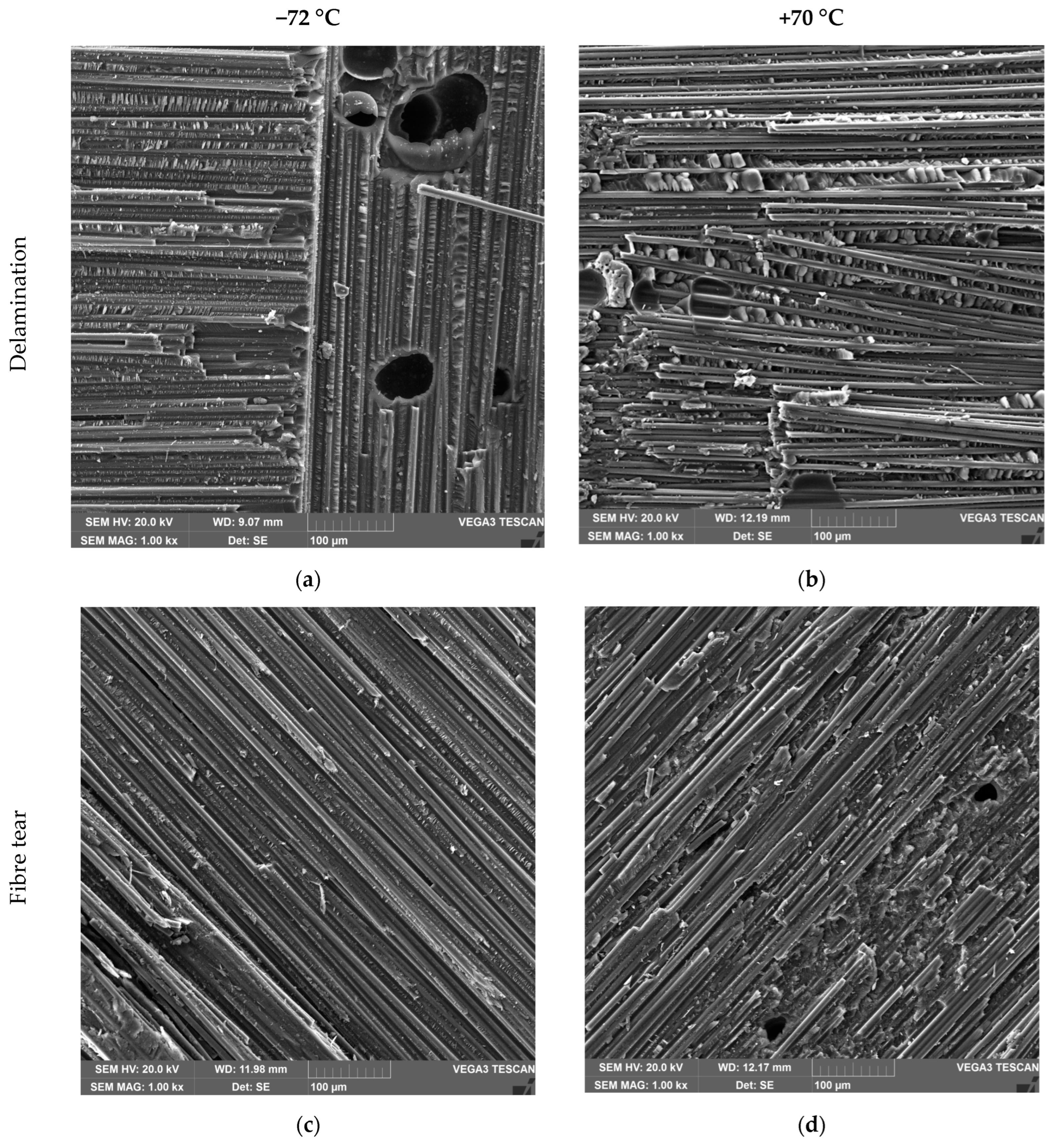
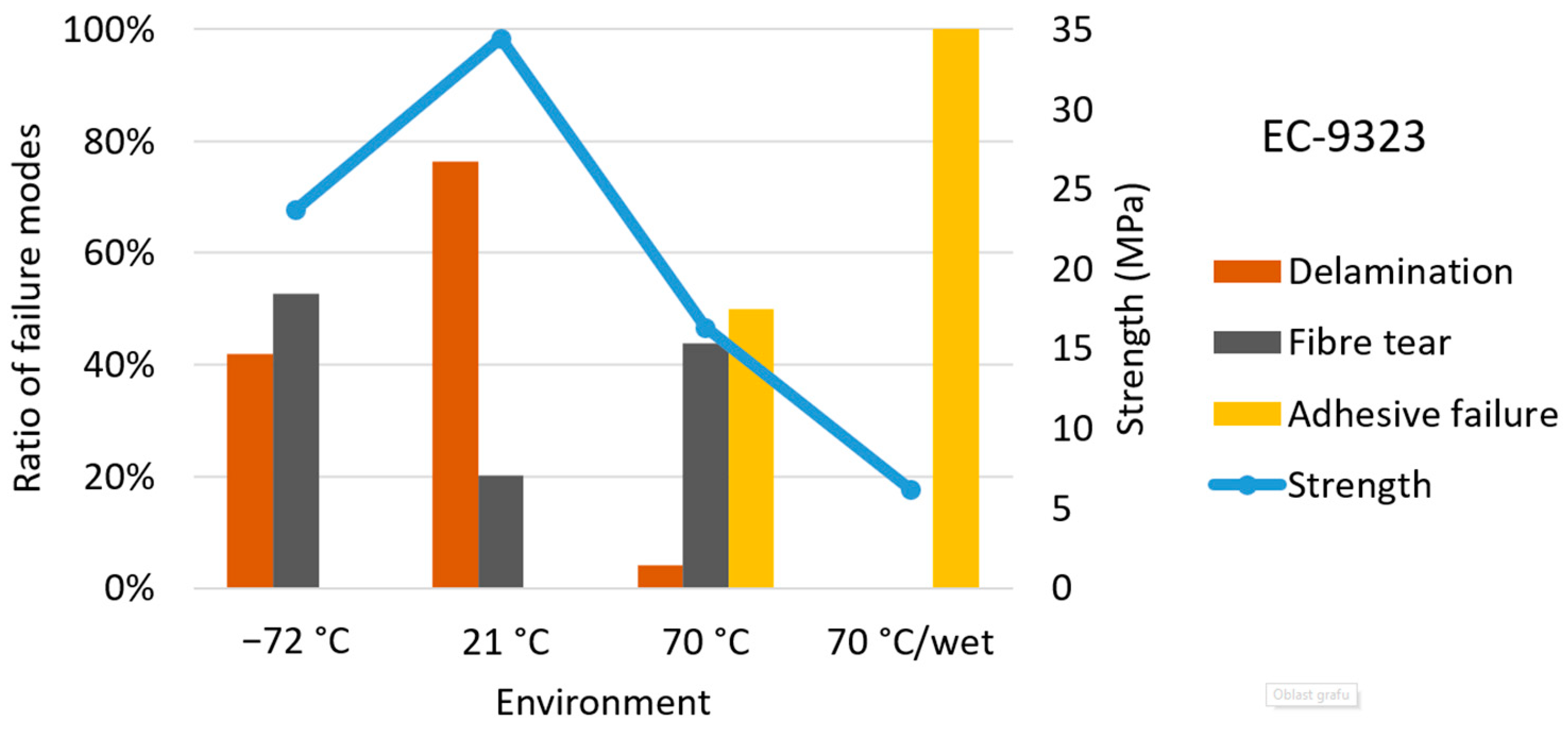
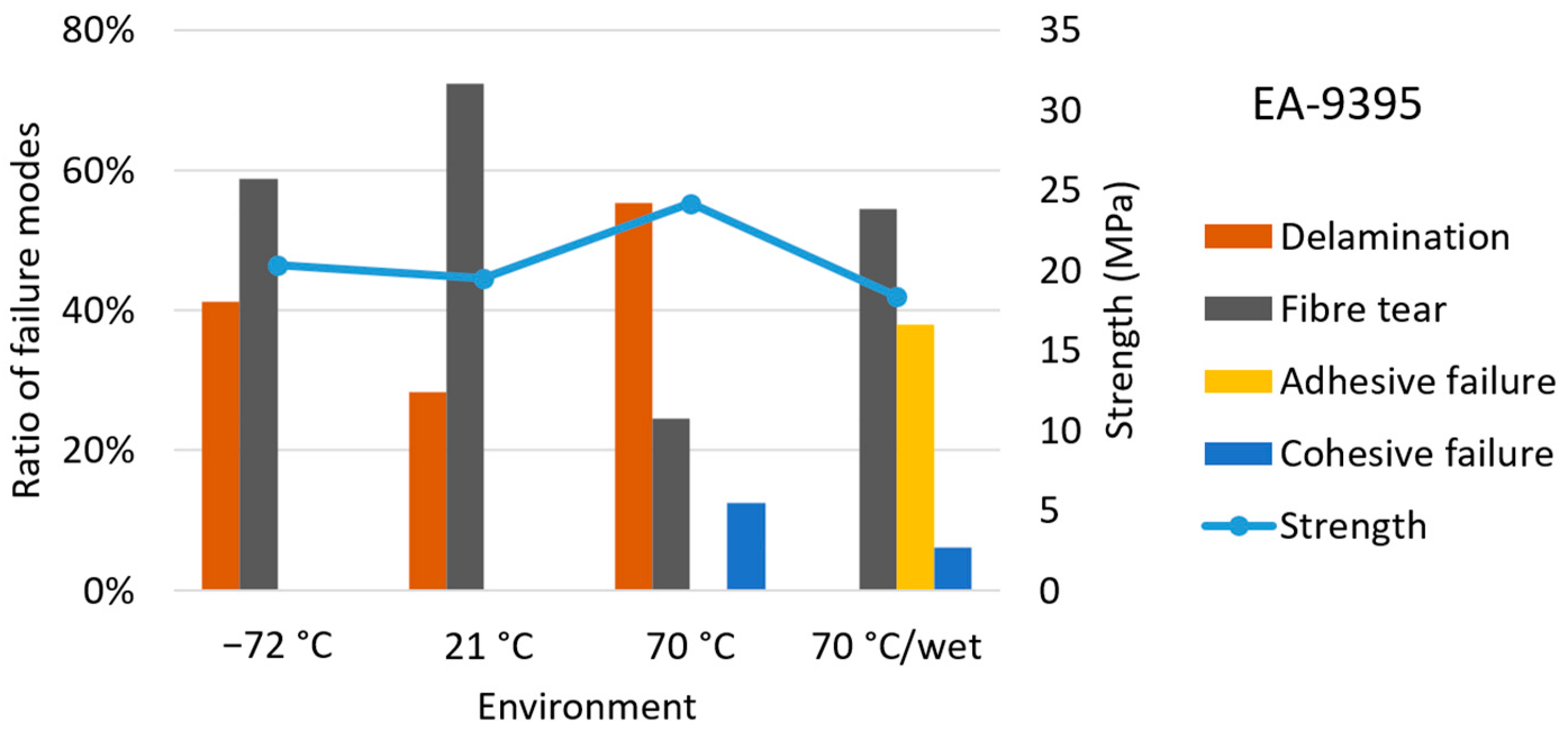
3.2. Failure Mode Analysis

The typical failure mechanism for double-sided strap joints is failure initiation at one of the four laps, which keeps the opposite lap intact (Figure 5). Then, the two laps on the other side of specimen fail simultaneously.
Multiple types of failure modes were observed on the fracture surfaces: cohesion failure, adhesive failure, fibre tear, and adherent delamination. Each fracture surface had multiple modes with a different ratio. The transition between the modes was observed via microfractography; the results are presented later in the article. Schematic pictures of the exclusive modes are visible in Figure 6a, with the actual appearance shown in Figure 6b.
Microfractographic analyses revealed detailed differences between two types of failure. Figure 7a shows the fracture surface of the delamination region that was dominated by shear cusps in between fibre tracks. These resin features are more prominent because the interlaminar region is more resin-rich than the actual fibre tow region. The second observed failure was fibre tear. Figure 7b shows the fracture surface of this intralaminar failure, which was dominated by fibres and fibre tracks with less resin deformation.
Another microfractographic examination was conducted to reveal the transition areas between different failure modes. All figures are oriented, so crack propagation is from left to right. Figure 8a shows the transition from debonding to fibre tear. The border line is linear, starting at the edge of the 90° fibre tow of the bottom fabric. Figure 8b presents the transition from cohesive failure to fibre tear. The transition is not uniform, which is probably caused by large pores (≈100 μm) in the adhesive. Figure 8c shows the transition from fibre tear to delamination. The border line is determined by the bottom 45° ply.
Detailed failure mode analysis of EC-9323 joints showed the following behaviour (Figure 9). The room-temperature fracture exhibited exceptional strength results because the joint itself transferred the load completely to the adherent; therefore, the major observed fracture surface was adherent delamination (Figure 9b). The cold-temperature fracture had a typical similar share of adherent fibre tear combined with adherent delamination split diagonally (Figure 9a). The second highest performance at a low temperature was diminished by the higher ratio of the fibre tear, most probably caused by residual stresses from the thermal expansion mismatch of the CFRP and the adhesive at a cold temperature (CT) [18]. Elevated temperatures initiated adhesive failure with fibre tear at a similar ratio (Figure 9c). This behaviour caused reduced strength below the level of CT as the adhesive–adherent interface was weakened by the high temperature. This usually occurs when the temperature approaches Tg, whereby the adhesive’s mechanical properties degrade significantly, leading to reduced bond strength and an increased likelihood of failure [33]. Elevated temperatures with absorbed moisture caused a very poor shear strength performance, as the fracture was caused by 100% adhesive failure (Figure 9d). Moisture absorption further degraded its mechanical properties and decreased Tg to the level of the test temperature. This led to premature failure [33]. Similar high-temperature and humidity degradation of adhesive performance was observed in Ref. [34], where the epoxy adhesive Araldite 2015 underwent a series of etherification and oxidation reactions. If the temperature was high enough, it promoted the etherification reaction. With the intrusion of moisture and heat, the section toughness fracture gradually shifted to a brittle fracture, and the joint failure mode gradually changed to adhesive failure.
Detailed failure mode analysis of EA-9395 joints showed the following fracture behaviour (Figure 10). Room-temperature and cold-temperature fractures exhibited similar strength results and fracture mode ratios (Figure 10a,b). Fibre tear was slightly more prevalent, and the rest of the surface presented adherent delamination. This means that thermal expansion did not cause significant stresses. This may also be connected to the greater adhesive thickness measured for this adhesive, which decreased the stress between the patch and the adherent. The joint performance at elevated temperatures was even better than at lower temperatures due to the transfer of the load to the adherent, and adherent delamination was prevalent (Figure 10c). Minor cohesive failure with a smooth surface was also observed. Elevated temperatures with absorbed moisture caused a slight decrease in shear strength performance; however, a very significant change in the fracture mode due to the high ratio of adhesive failure was observed (Figure 10d). Similar behaviour was observed in Refs. [30,34], where the wet environment caused a change from adhesive failure in the dry state to fibre tear in the wet state. This could be caused by the increased sensitivity of the laminate to humidity.
The effect of temperature on the fracture surface was also studied with microfractographic images. Figure 11 shows a matrix of images for delamination and fibre tear at two different temperatures. It is evident that the fracture at a low temperature of −72 °C had smooth surfaces and the fracture at +70 °C had significant fibre pull-out for both delamination and fibre tear. The reason behind this observation is interfacial strength reduction at elevated temperatures [20].
Figure 12 and Figure 13 show combined graphs of the failure mode ratios and shear strength results. The analysis of EC-9323 adhesive joints showed the significant impact of adhesive failure on shear strength (Figure 12). The analysis of EA-9395 adhesive joints showed relatively similar mode ratios at all temperatures for dry specimens. The strength variations between the environments were also quite low. On wet specimens, adhesive failure was significant (Figure 13).
A similar trend was found for both adhesives. Figure 14 shows the relationship between the delamination failure ratio and shear strength. The linear increase in strength with adherent delamination shows how the stronger adhesive transfers the stress to the adherents. The shear strength of the adherents in the specific environment is then the limiting factor. However, this study is not focused on laminate shear strength and rather investigates the adhesives. The similarity in slope trends proves that the environment primarily affected the adhesive and not the adherents, which bore the stress at the same level.

4. Conclusions

The shear loading behaviour and performance of two epoxy adhesives named EC-9323 and EA-9395 were studied. The shear strength and respective failure modes were determined via double-lap joint testing under four different environmental conditions ranging from −72 °C to +70 °C unconditioned and +70 °C wet. The following conclusions can be drawn.
The results show that EC-9323 performed excellently at room temperature, but very poorly at elevated temperatures after hot–wet conditioning. Adhesive EA-9395 performed consistently well across all tested conditions.
The cold environment caused a 30% decrease in strength for EC-9323; however, it had no significant effect on EA-9395 compared to room temperature. The decreased temperature caused a greater fibre tear ratio for EC-9323, which can be explained by the weakened adhesive/laminate interface due to thermal expansion mismatch.
The elevated temperature caused a 50% decrease in strength for EC-9323 compared to room temperature. Adhesive failure was prevalent for the hot environment as the adhesive–adherent interface was weakened. For EA-9395, at an elevated temperature, there was a proportional increase in strength as the delamination ratio increased. However, a minor cohesive fracture was also observed at an elevated temperature.
Moisture decreased the strength of EC-9323 even more, up to 80% below the strength at room temperature, as the failure mode was 100% adhesive. This was probably caused by a decrease in Tg to the level of the test temperature due to the absorbed humidity. For EA-9395, the adhesive failure was quite significant; however, the strength was not affected.
Microfractographic analyses revealed detailed differences between two types of failure—fibre tear and delamination. Another examination was performed to reveal the transition areas between the different failure modes and the effect of low and elevated temperatures. The presence of fibre pull-out observed for the high-temperature test was in line with the findings in the literature.
The failure mode macroanalysis explained the performance trends and helped with the selection of the adhesive to be used for proper repair design. These findings are crucial for the development of numerical models where the failure modes determine the failure criterion used for joint strength prediction.

Author Contributions

Conceptualization, B.C.; methodology, M.K. and B.C.; validation, R.H.; investigation, M.K.; data curation, R.H.; writing—original draft preparation, M.K.; writing—review and editing, B.C.; visualization, M.K.; supervision, B.C. All authors have read and agreed to the published version of the manuscript.

Funding

The work presented in this article is co-financed by the state support of the Technology Agency of the Czech Republic under the National Centres of Competence, project National Competence Centre for Aeronautics and Space, sub-project Modern manufacturing Processes, under grant agreement No TN02000009/05.

Data Availability Statement

The data can be provided upon request.

Conflicts of Interest

All authors are employed by VZLU—Czech Aerospace Research Centre.

References

  1. Kupski, J.; Teixeira de Freitas, S. Design of Adhesively Bonded Lap Joints with Laminated CFRP Adherends: Review, Challenges and New Opportunities for Aerospace Structures. Compos. Struct. 2021, 268, 113923. [Google Scholar] [CrossRef]
  2. Hart-Smith, J. Aerospace Industry Applications of Adhesive Bonding. In Adhesive Bonding: Science, Technology and Applications; Woodhead Publishing: Sawston, UK, 2021; pp. 763–800. [Google Scholar] [CrossRef]
  3. Kadlec, M.; Růžek, R.; Bělský, P. Concurrent Use of Z-Pins for Crack Arrest and Structural Health Monitoring in Adhesive-Bonded Composite Lap Joints. Compos. Sci. Technol. 2020, 188, 107967. [Google Scholar] [CrossRef]
  4. Körwien, T.; Růžek, R.; Hangx, R.; Rans, C. Fatigue Behavior and Damage Tolerant Design of Bonded Joints for Aerospace Application on Fibre Metal Laminates and Composites. In Proceedings of the 29th Symposium of the International Committee on Aeronautical Fatigue (ICAF 2017), Nagoya, Japan, 5–9 June 2017. [Google Scholar]
  5. Jiang, H.; Liao, Y.; Gao, S.; Li, G.; Cui, J. Comparative Study on Joining Quality of Electromagnetic Driven Self-Piecing Riveting, Adhesive and Hybrid Joints for Al/Steel Structure. Thin-Walled Struct. 2021, 164, 107903. [Google Scholar] [CrossRef]
  6. Zhang, J.; Cheng, X.; Guo, X.; Bao, J.; Huang, W. Effect of Environment Conditions on Adhesive Properties and Material Selection in Composite Bonded Joints. Int. J. Adhes. Adhes. 2020, 96, 102302. [Google Scholar] [CrossRef]
  7. Moraes, C.E.; Santos, L.F.P.; Leal, T.P.F.G.; Costa, M.L.; Botelho, E.C. Moisture Sorption Behavior of an Epoxy-Based Structural Adhesive and Its Impact on the Mode I Interlaminar Fracture Toughness of Bonded Joints in the Oil and Gas Industry. Int. J. Adhes. Adhes. 2024, 134, 103799. [Google Scholar] [CrossRef]
  8. Guo, J.; Zhan, L.; Ma, B.; Zhang, D.; Fan, Y.; Yao, S.; Feng, J. A Review on Failure Mechanism and Mechanical Performance Improvement of FRP-Metal Adhesive Joints under Different Temperature-Humidity. Thin-Walled Struct. 2023, 188, 110788. [Google Scholar] [CrossRef]
  9. Aceti, P.; Carminati, L.; Bettini, P.; Sala, G. Hygrothermal Ageing of Composite Structures. Part 1: Technical Review. Compos. Struct. 2023, 319, 117076. [Google Scholar] [CrossRef]
  10. Nguyen, T.C.; Bai, Y.; Zhao, X.L.; Bambach, M.R.; Al-Mahaidi, R. Temperature Effect on Adhesively Bonded CFRP and Steel Double Strap Joints. In Advances in FRP Composites in Civil Engineering—Proceedings of the 5th International Conference on FRP Composites in Civil Engineering, CICE 2010, Beijing, China, 27–29 September 2010; Springer: Berlin/Heidelberg, Germany, 2010; pp. 877–880. [Google Scholar] [CrossRef]
  11. Zhang, H.; Song, Z.; Zhang, L.; Liu, Z.; Zhu, P. Effects of Hygrothermal Ageing and Temperature on the Mechanical Behavior of Aluminum-CFRP Hybrid (Riveted/Bonded) Joints. Int. J. Adhes. Adhes. 2023, 121, 103299. [Google Scholar] [CrossRef]
  12. Vigón, P.; Argüelles, A.; Lozano, M.; Viña, J. Mode II Delamination under Static and Fatigue Loading of Adhesive Joints in Composite Materials Exposed to Saline Environment. Materials 2023, 16, 7606. [Google Scholar] [CrossRef]
  13. Ren, X.; Sherif, M.M.; Wei, Y.; Lyu, Y.; Sun, Y.; Ozbulut, O.E. Effect of Corrosion on the Tensile and Fatigue Performance of CFRP Strand Sheet/Steel Double Strap Joints. Eng. Struct. 2022, 260, 114240. [Google Scholar] [CrossRef]
  14. Tan, W.; Na, J.; Zhou, Z. Effect of Service Temperature on Mechanical Properties of Adhesive Joints after Hygrothermal Aging. Polymers 2021, 13, 3741. [Google Scholar] [CrossRef]
  15. Kang, S.G.; Kim, M.G.; Kim, C.G. Evaluation of Cryogenic Performance of Adhesives Using Composite–Aluminum Double-Lap Joints. Compos. Struct. 2007, 78, 440–446. [Google Scholar] [CrossRef]
  16. Aliheidari, N.; Ameli, A. Retaining High Fracture Toughness in Aged Polymer Composite/Adhesive Joints through Optimization of Plasma Surface Treatment. Compos. Part A Appl. Sci. Manuf. 2024, 176, 107835. [Google Scholar] [CrossRef]
  17. Chen, H.; Na, J.; Wang, D.; Kong, D.; Zhang, X. Numerical Simulation and Failure Experiment of Hygrothermal Aged CFRP Single and Double Lap Joints. Thin-Walled Struct. 2023, 188, 110786. [Google Scholar] [CrossRef]
  18. Su, T.; Zhou, H.; Wang, R.; Chen, Y.; Luo, W.; Li, M. Effects of Working Temperature on Mechanical Performance and Failure Characteristics of Carbon Fibre Reinforced Plastic and Adhesive–Repaired Titanium Structures with Central Inclined Cracks. J. Mater. Eng. Perform. 2023, 32, 1824–1839. [Google Scholar] [CrossRef]
  19. Michels, J.; Widmann, R.; Czaderski, C.; Allahvirdizadeh, R.; Motavalli, M. Glass Transition Evaluation of Commercially Available Epoxy Resins Used for Civil Engineering Applications. Compos. B Eng. 2015, 77, 484–493. [Google Scholar] [CrossRef]
  20. De Leon, A.; Sweat, R.D. Interfacial Engineering of CFRP Composites and Temperature Effects: A Review. Mech. Compos. Mater. 2023, 59, 419–440. [Google Scholar] [CrossRef]
  21. D5573; Standard Practice for Classifying Failure Modes in Fibre-Reinforced-Plastic (FRP) Joints. ASTM International: West Conshohocken, PA, USA, 2019. Available online: https://www.astm.org/d5573-99r19.html (accessed on 15 November 2024).
  22. Qiao, Y.; Seffens, R.J.; Nickerson, E.K.; Roosendaal, T.J.; Merkel, D.R.; Shin, Y.; Ramos, J.L.; Ko, S.; Samanta, A.; Pallaka, M.R.; et al. A Study of Adhesive Bonding in Metal–Metal, Metal–CFRP, and CFRP–CFRP Material Combinations under Shear Deformation: Fracture Morphologies and Damage Mechanisms. Int. J. Adhes. Adhes. 2023, 127, 103511. [Google Scholar] [CrossRef]
  23. Omairey, S.; Jayasree, N.; Kazilas, M. Defects and Uncertainties of Adhesively Bonded Composite Joints. SN Appl. Sci. 2021, 3, 769. [Google Scholar] [CrossRef]
  24. Tsai, M.Y.; Morton, J. An Investigation into the Stresses in Double-Lap Adhesive Joints with Laminated Composite Adherends. Int. J. Solids Struct. 2010, 47, 3317–3325. [Google Scholar] [CrossRef]
  25. Adams, R.D. Prediction of the Strength of Adhesive Lap Joints. An Investigative Review. Int. J. Adhes. Adhes. 2024, 129, 103576. [Google Scholar] [CrossRef]
  26. D3528; Standard Test Method for Strength Properties of Double Lap Shear Adhesive Joints by Tension Loading. ASTM International: West Conshohocken, PA, USA, 2024. Available online: https://www.astm.org/standards/d3528 (accessed on 15 November 2024).
  27. Kanerva, M.; Sarlin, E.; Hoikkanen, M.; Rämö, K.; Saarela, O.; Vuorinen, J. Interface Modification of Glass Fibre–Polyester Composite–Composite Joints Using Peel Plies. Int. J. Adhes. Adhes. 2015, 59, 40–52. [Google Scholar] [CrossRef]
  28. Guo, L.; Liu, J.; Xia, H.; Li, X.; Zhang, X.; Yang, H. Effects of Surface Treatment and Adhesive Thickness on the Shear Strength of Precision Bonded Joints. Polym. Test. 2021, 94, 107063. [Google Scholar] [CrossRef]
  29. D5229/D5229M; Standard Test Method for Moisture Absorption Properties and Equilibrium Conditioning of Polymer Matrix Composite Materials. ASTM International: West Conshohocken, PA, USA, 2020. Available online: https://www.astm.org/d5229_d5229m-20.html (accessed on 15 November 2024).
  30. Li, W.; Zeng, R.; Zhang, Q.; Duan, Z.; Shen, P.; Zhong, X.; Jiang, S.; Bao, J. A Study of the Effects of Moisture on Composite−to−Metal Double−Lap Shear Joints. Materials 2024, 17, 3841. [Google Scholar] [CrossRef]
  31. Hu, P.; Han, X.; Li, W.D.; Li, L.; Shao, Q. Research on the Static Strength Performance of Adhesive Single Lap Joints Subjected to Extreme Temperature Environment for Automotive Industry. Int. J. Adhes. Adhes. 2013, 41, 119–126. [Google Scholar] [CrossRef]
  32. Structural Adhesive Aerospace Product Selector Guide. Henkel Adhesives. Available online: https://next.henkel-adhesives.com/us/en/brochures/structural-adhesive-aerospace-product-selector-guide.html (accessed on 15 November 2024).
  33. Bao, Y.; Xie, Y.; Li, S.; Wang, W.; Liu, Y.; Chen, W.; Liu, C.; Li, N. Bond Performance of CFRP/Steel Double Strap Joint at Elevated Temperatures. Sustainability 2022, 14, 15537. [Google Scholar] [CrossRef]
  34. Peng, H.; Zhou, T.; Shangguan, L.; Cheng, R. Effect of Temperature and Humidity Coupling on the Ageing Failure of Carbon Fibre Composite/Titanium Bonded Joints. Polymers 2024, 16, 952. [Google Scholar] [CrossRef] [PubMed]
Figure 1. Double-sided strap joint specimen geometry.
Jcs 08 00511 g001
Figure 2. Detail of double-sided strap joint bonded by (a) EC-9323 and (b) EA-9395.
Jcs 08 00511 g002
Figure 3. Measured adhesive thickness: (a) average values were 138 μm and 275 μm for EC-9323 and EA-9395, respectively; (b) details of adhesive layer.
Jcs 08 00511 g003
Figure 4. Shear strength results for (a) EC-9323 and (b) EA-9395.
Jcs 08 00511 g004
Figure 5. The typical failure mechanism for double-sided strap joints. One of the laps remains intact as the opposite lap initiates the failure.
Jcs 08 00511 g005
Figure 6. Observed failure modes: (a) schematic diagram; (b) actual fracture surface.
Jcs 08 00511 g006
Figure 7. Observed failure modes: (a) fracture surface of delamination (interlaminar failure) region was dominated by shear cusps (white) in between fibre tracks (black); (b) fracture surface of fibre tear (intralaminar failure) region was dominated by fibres and fibre tracks with less resin/adhesive deformation.
Jcs 08 00511 g007
Figure 8. Observed failure mode transition: (a) from debonding to fibre tear; (b) from cohesive failure to fibre tear; (c) from fibre tear to delamination. Propagation from left to right.
Jcs 08 00511 g008
Figure 9. Failure mode analysis of EC-9323 at various test temperatures: (a) −72 °C; (b) 21 °C; (c) 70 °C; and (d) 70 °C after wet conditioning. Initiation occurred on top side of imaged surfaces.
Jcs 08 00511 g009
Figure 10. Failure mode analysis of EA-9395 at various test temperatures: (a) −72 °C; (b) 21 °C; (c) 70 °C; and (d) 70 °C after wet conditioning. Initiation occurred on top side of imaged surfaces.
Jcs 08 00511 g010
Figure 11. Differences in fracture surfaces at low and high temperatures for delamination and fibre tear: (a,c) relatively smooth surface at −72 °C, and (b,d) significant fibre pull-out at 70 °C. Propagation from left to right.
Jcs 08 00511 g011
Figure 12. Failure mode analysis of EC-9323 adhesive joints. The significant impact of adhesive failure on shear strength is apparent.
Jcs 08 00511 g012
Figure 13. Failure mode analysis of EA-9395 adhesive joints. Wet environment degradation caused an increase in the adhesive failure ratio.
Jcs 08 00511 g013
Figure 14. Delamination failure ratio relationship with shear strength. Linear increase in strength with delamination ratio observed for both adhesives.
Jcs 08 00511 g014
Table 1. Adherent and patch material properties at room temperature.
Material PropertiesAdherentStrap
Tensile strength (MPa)410690
Young’s modulus (GPa)3155
Table 2. Test matrix. Two types of adhesives in four different environments.
Adhesive TypeNumber of Tested Samples
UnconditionedWet Conditioned 70 °C/85%r.h.
Tested at
−72 °C
Tested at
21 °C
Tested at
70 °C
Tested at
70 °C
EC-93236666
EA-93956666
Table 3. Shear strength results for EC-9323.
EnvironmentShear Strength (MPa)Observed Failure Modes
(in Order of Prevalence)
−72 °C23.7 ± 2.40Fibre tear, delamination
21 °C34.5 ± 0.89delamination, fibre tear
70 °C16.3 ± 0.60adhesive, fibre tear
70 °C/wet6.16 ± 0.56adhesive
Table 4. Shear strength results for EA-9395.
EnvironmentShear Strength (MPa)Observed Failure Modes
(in Order of Prevalence)
−72 °C20.32 ± 0.53Fibre tear, delamination
21 °C19.50 ± 1.04fibre tear, delamination
70 °C24.15 ± 1.13delamination, fibre tear, cohesive
70 °C/wet18.38 ± 1.32fibre tear, cohesive
Disclaimer/Publisher’s Note: The statements, opinions and data contained in all publications are solely those of the individual author(s) and contributor(s) and not of MDPI and/or the editor(s). MDPI and/or the editor(s) disclaim responsibility for any injury to people or property resulting from any ideas, methods, instructions or products referred to in the content.

