
Evaluation of Bonding Properties Between CFRP Laminate and Concrete Using Externally Bonded Reinforcement on Transverse Grooves (EBROTG) Method


Abstract
1. Introduction
2. Experimental Program
2.1. Specimens Layout
2.2. Materials Properties
2.3. Specimen Preparation and Reinforcement
2.4. Test Configuration and Set-Up
3. Results and Discussion
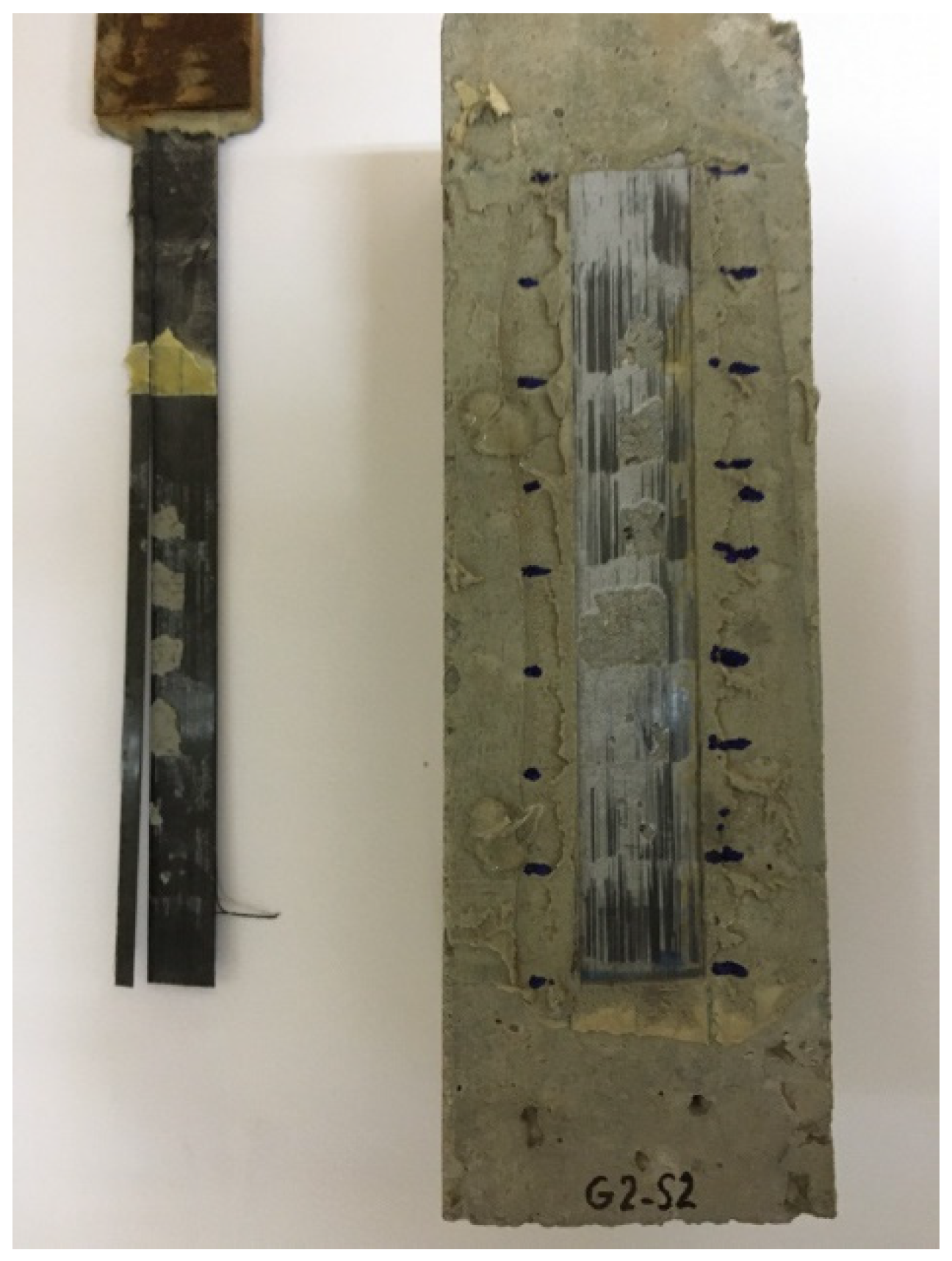
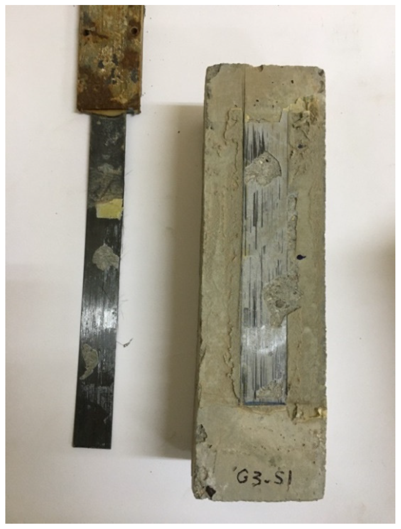
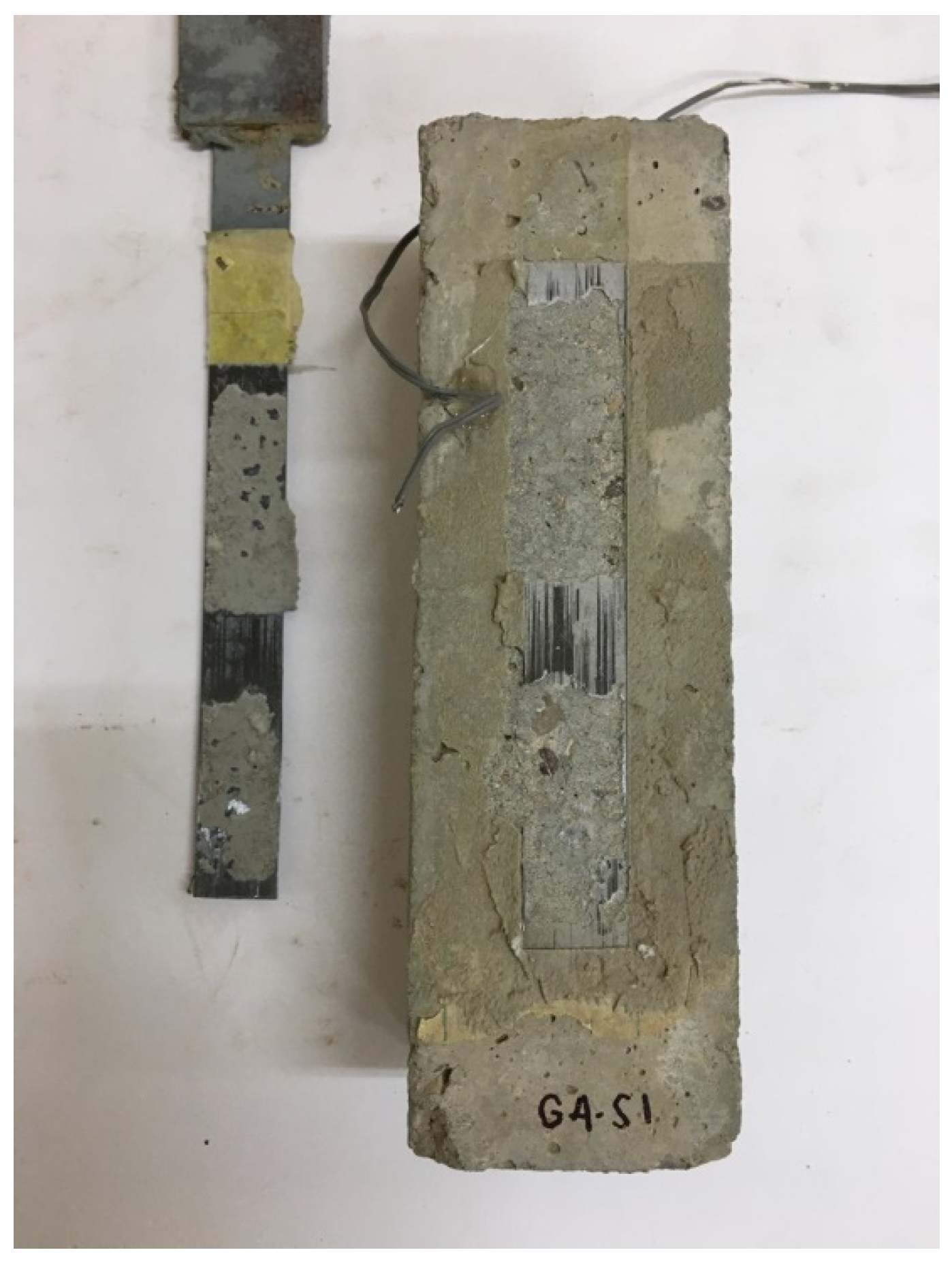
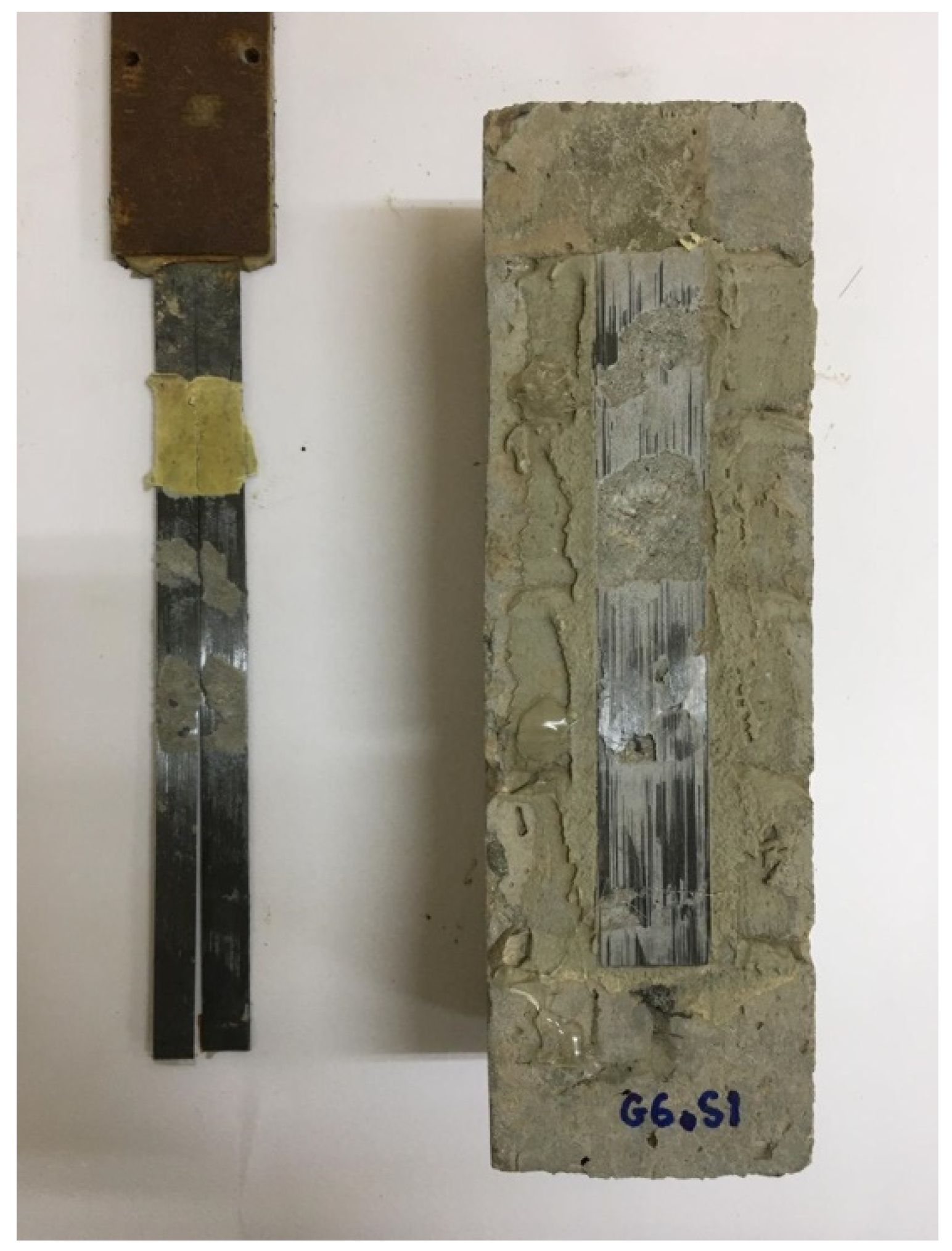
3.1. Mode of Failure
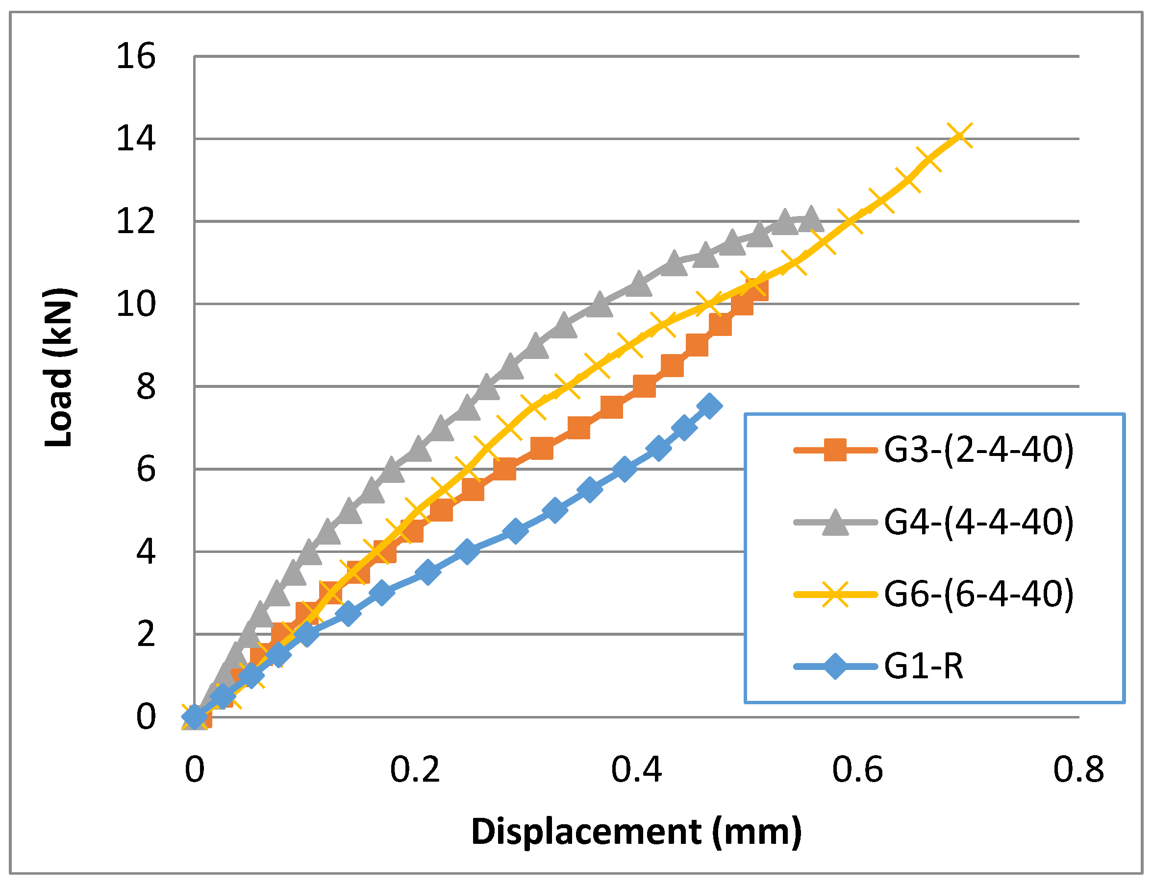
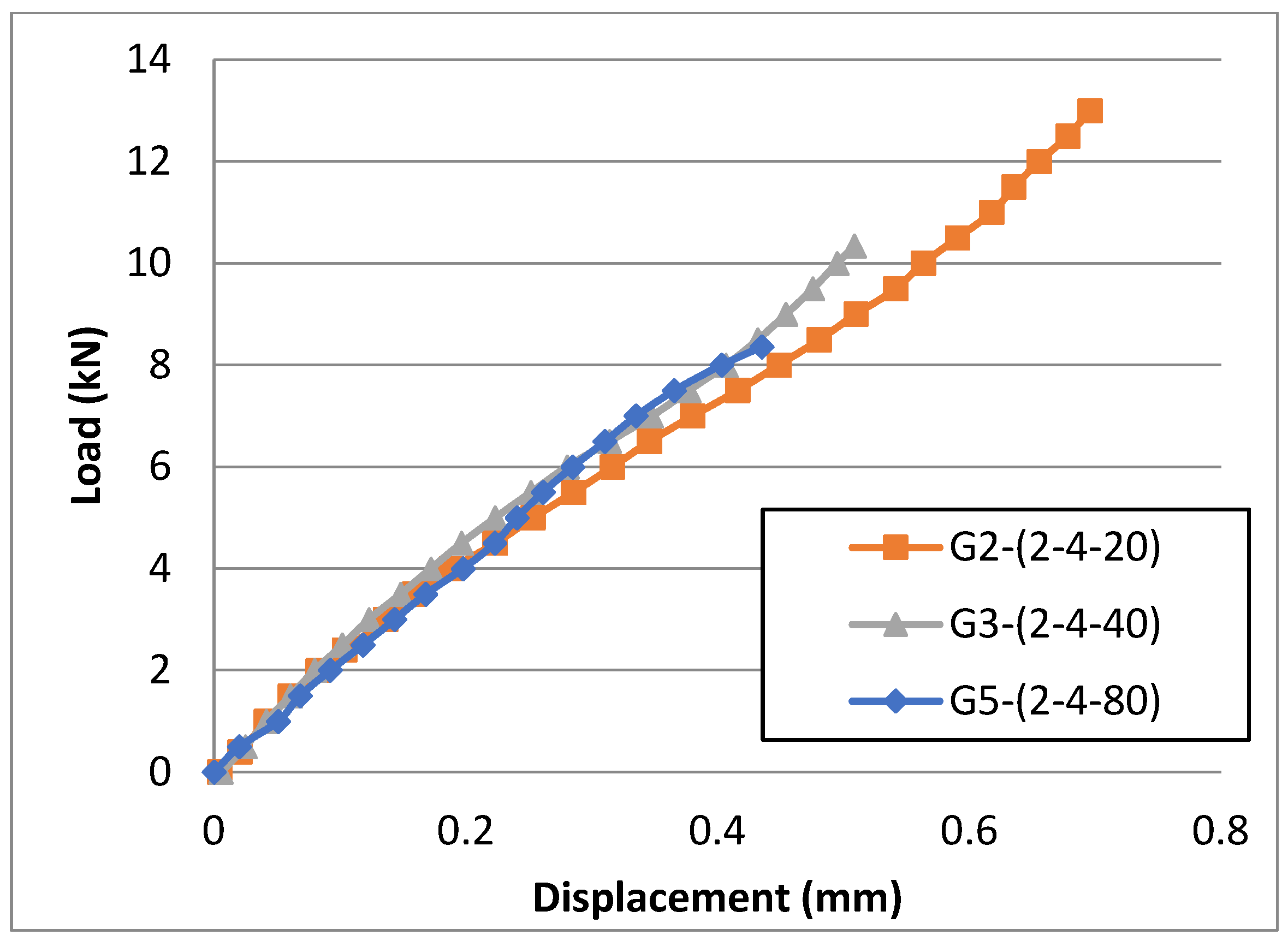
3.2. Bond Strength
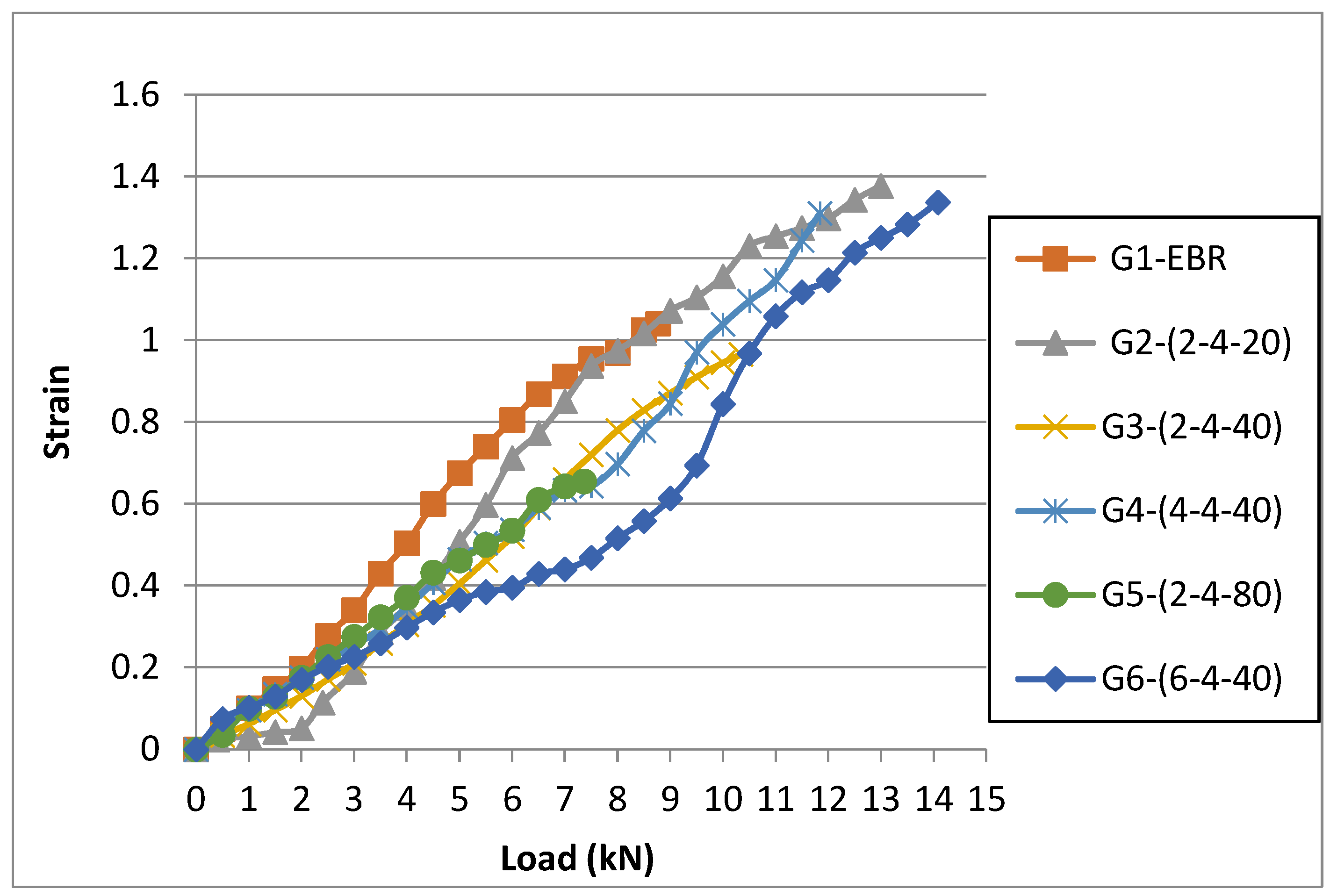
3.3. Strain Values
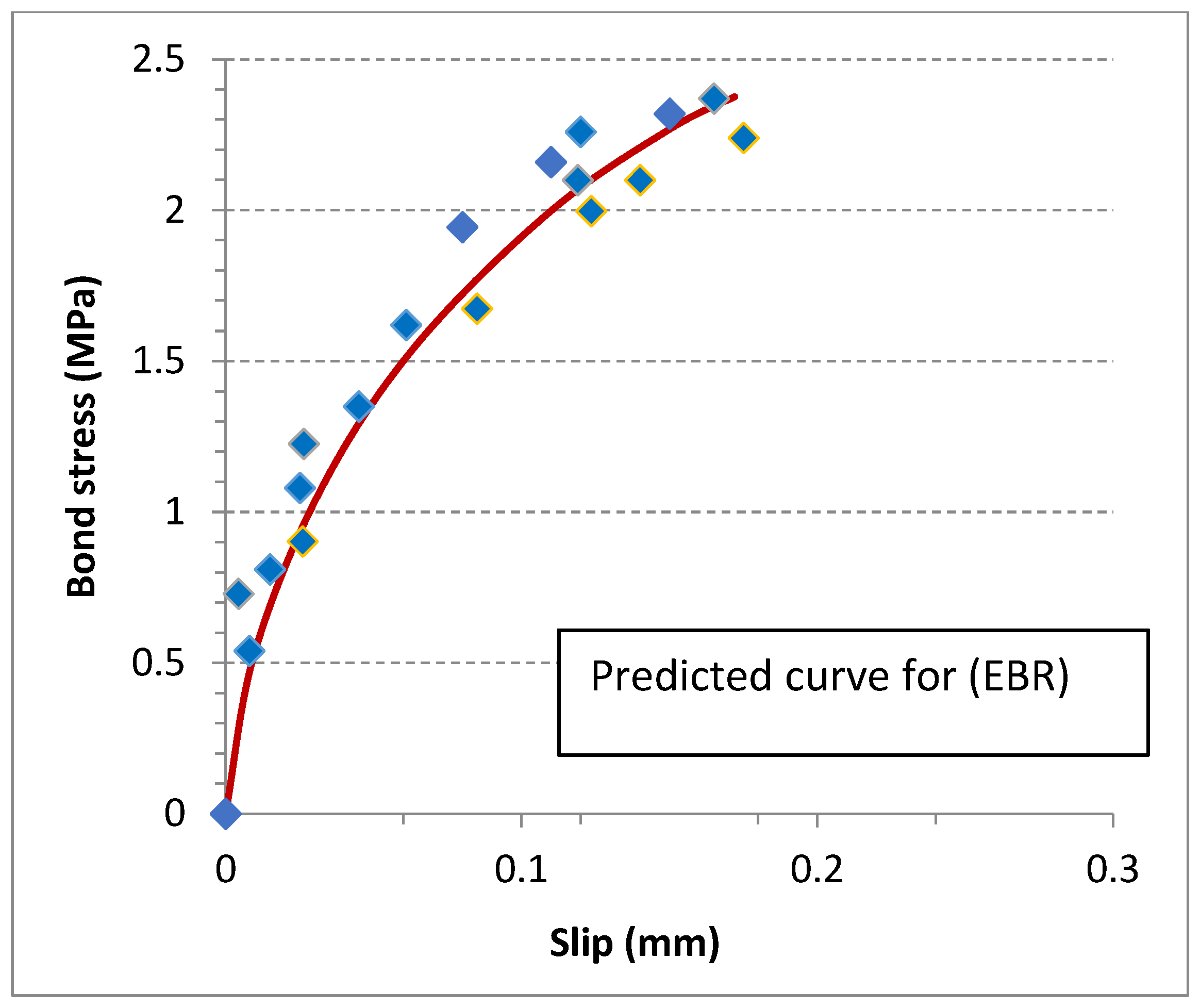
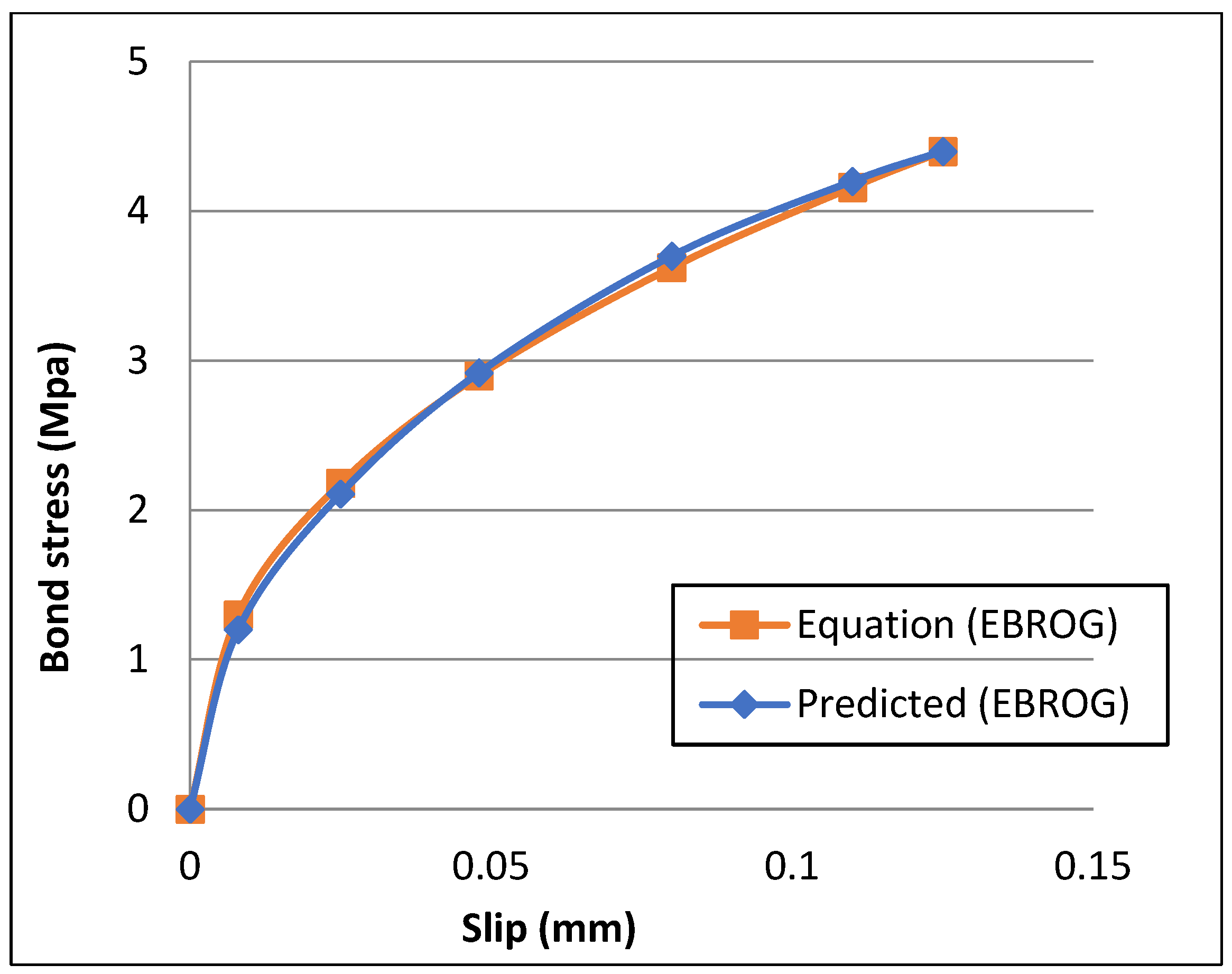
3.4. Local Bond Stress–Slip Value
4. Conclusions
- The results showed significant improvement in bond strength using the EBROTG method by delaying the debonding of the CFRP, when compared to specimens strengthened using the EBR method. The specimens strengthened using the EBROTG approach showed an improvement of 11 to 86% in bond strength according to the groove dimensions.
- The effect of groove width has noteworthy consequences on bond strength. Increasing the groove width to 2, 4, and 6 mm improved the bond strength by 37%, 60%, and 86%, respectively, compared with EBR specimens.
- The distances between grooves with identical groove section dimensions have a significant effect when increasing the distances by 2, 4, and 8 mm. The bond strength decreased from 13 to 10.34 and 8.36 kN (from 72% to 37% and 11%), respectively. By combining the effects of the width and the distances between grooves, it can be concluded that the total cross-section area of the grooves at a certain bonding length and their distribution along this bonding length are crucial factors in determining the increase in the bonding strength.
- The findings showed that there was no significant increase in bond strength as groove depth increased since there was no failure observed in the concrete surrounding the grooves.
- Bond stress–slip diagrams were extracted from the different strain gages along the bonding length, and the predicted curves can be utilized in the finite element modeling of concrete members strengthened using the EBROTG method.
Author Contributions
Funding
Data Availability Statement
Acknowledgments
Conflicts of Interest
References
- Meier, U. Strengthening of structures using carbon fibre/epoxy composites. Constr. Build. Mater. 1995, 9, 341–351. [Google Scholar] [CrossRef]
- Yao, J.; Teng, J. Plate end debonding in FRP-plated RC beams—I: Experiments. Eng. Struct. 2007, 29, 2457–2471. [Google Scholar] [CrossRef]
- Tajmir-Riahi, A.; Moshiri, N.; Mostofinejad, D. Inquiry into bond behavior of CFRP sheets to concrete exposed to elevated temperatures–Experimental & analytical evaluation. Compos. Part B Eng. 2019, 173, 106897. [Google Scholar]
- Gao, P.; Gu, X.; Mosallam, A.S. Flexural behavior of preloaded reinforced concrete beams strengthened by prestressed CFRP laminates. Compos. Struct. 2016, 157, 33–50. [Google Scholar] [CrossRef]
- Martinelli, E.; Hosseini, A.; Ghafoori, E.; Motavalli, M. Behavior of prestressed CFRP plates bonded to steel substrate: Numerical modeling and experimental validation. Compos. Struct. 2019, 207, 974–984. [Google Scholar] [CrossRef]
- Hosseini, A.; Nussbaumer, A.; Motavalli, M.; Zhao, X.-L.; Ghafoori, E. Mixed mode I/II fatigue crack arrest in steel members using prestressed CFRP reinforcement. Int. J. Fatigue 2019, 127, 345–361. [Google Scholar] [CrossRef]
- Mosallam, A.; Banerjee, S. Enhancement in in-plane shear capacity of unreinforced masonry (URM) walls strengthened with fiber reinforced polymer composites. Compos. Part B Eng. 2011, 42, 1657–1670. [Google Scholar] [CrossRef]
- Hosseini, A.; Mostofinejad, D.; Emami, M. Influence of bonding technique on bond behavior of CFRP-to-clay brick masonry joints: Experimental study using particle image velocimetry (PIV). Int. J. Adhes. Adhes. 2015, 59, 27–39. [Google Scholar] [CrossRef]
- Ali, A.; Abdalla, J.; Hawileh, R.; Galal, K. CFRP mechanical anchorage for externally strengthened RC beams under flexure. Phys. Procedia 2014, 55, 10–16. [Google Scholar] [CrossRef]
- Yu, P.; Silva, P.F.; Nanni, A. Description of a mechanical device for prestressing of carbon fiber-reinforced polymer sheets-Part I. ACI Struct. J. 2008, 105, 3–10. [Google Scholar]
- Michels, J.; Martinelli, E.; Czaderski, C.; Motavalli, M. Prestressed CFRP strips with gradient anchorage for structural concrete retrofitting: Experiments and numerical modeling. Polymers 2014, 6, 114–131. [Google Scholar] [CrossRef]
- Pham, H.B.; Al-Mahaidi, R. Prediction models for debonding failure loads of carbon fiber reinforced polymer retrofitted reinforced concrete beams. J. Compos. Constr. 2006, 10, 48–59. [Google Scholar] [CrossRef]
- Kim, Y.J.; Wight, R.G.; Green, M.F. Flexural strengthening of RC beams with prestressed CFRP sheets: Development of nonmetallic anchor systems. J. Compos. Constr. 2008, 12, 35–43. [Google Scholar] [CrossRef]
- Michels, J.; Sena-Cruz, J.; Czaderski, C.; Motavalli, M. Structural strengthening with prestressed CFRP strips with gradient anchorage. J. Compos. Constr. 2013, 17, 651–661. [Google Scholar] [CrossRef]
- Bilotta, A.; Ceroni, F.; Di Ludovico, M.; Nigro, E.; Pecce, M.; Manfredi, G. Bond efficiency of EBR and NSM FRP systems for strengthening concrete members. J. Compos. Constr. 2011, 15, 757–772. [Google Scholar] [CrossRef]
- Hajihashemi, A.; Mostofinejad, D.; Azhari, M. Investigation of RC beams strengthened with prestressed NSM CFRP laminates. J. Compos. Constr. 2011, 15, 887–895. [Google Scholar] [CrossRef]
- Al-Abdwais, A.; Al-Mahaidi, R. Experimental and finite element analysis of flexural performance of RC beams retrofitted using near-surface mounted with CFRP composites and cement adhesive. Eng. Struct. 2021, 241, 112429. [Google Scholar] [CrossRef]
- Mostofinejad, D.; Mahmoudabadi, E. Grooving as alternative method of surface preparation to postpone debonding of FRP laminates in concrete beams. J. Compos. Constr. 2010, 14, 804–811. [Google Scholar] [CrossRef]
- Mostofinejad, D.; Shameli, S.M.; Hosseini, A. EBROG and EBRIG methods for strengthening of RC beams by FRP sheets. Eur. J. Environ. Civ. Eng. 2014, 18, 652–668. [Google Scholar] [CrossRef]
- Moshiri, N.; Tajmir-Riahi, A.; Mostofinejad, D.; Czaderski, C.; Motavalli, M. Experimental and analytical study on CFRP strips-to-concrete bonded joints using EBROG method. Compos. Part B Eng. 2019, 158, 437–447. [Google Scholar] [CrossRef]
- Tajmir-Riahi, A.; Moshiri, N.; Mostofinejad, D. Bond mechanism of EBROG method using a single groove to attach CFRP sheets on concrete. Constr. Build. Mater. 2019, 197, 693–704. [Google Scholar] [CrossRef]
- Mostofinejad, D.; Shameli, S.M. Externally bonded reinforcement in grooves (EBRIG) technique to postpone debonding of FRP sheets in strengthened concrete beams. Constr. Build. Mater. 2013, 38, 751–758. [Google Scholar] [CrossRef]
- Czaderski, C.; Moshiri, N.; Hosseini, A.; Mostofinejad, D.; Motavalli, M. EBROG technique to enhance the bond performance of CFRP strips to concrete substrate. In Proceedings of the SMAR 2019-Fifth Conference on Smart Monitoring, Assessment and Rehabilitation of Civil Structures, Potsdam, Germany, 27–29 August 2019. [Google Scholar]
- Shomali, A.; Mostofinejad, D.; Esfahani, M.R. Experimental and numerical investigation of shear performance of RC beams strengthened with FRP using grooving method. J. Build. Eng. 2020, 31, 101409. [Google Scholar] [CrossRef]
- Mostofinejad, D.; Hosseini, S.A.; Razavi, S.B. Influence of different bonding and wrapping techniques on performance of beams strengthened in shear using CFRP reinforcement. Constr. Build. Mater. 2016, 116, 310–320. [Google Scholar] [CrossRef]
- Moshiri, N.; Hosseini, A.; Mostofinejad, D. Strengthening of RC columns by longitudinal CFRP sheets: Effect of strengthening technique. Constr. Build. Mater. 2015, 79, 318–325. [Google Scholar] [CrossRef]
- Mostofinejad, D.; Moshiri, N. Compressive strength of CFRP composites used for strengthening of RC columns: Comparative evaluation of EBR and grooving methods. J. Compos. Constr. 2014, 19, 04014079. [Google Scholar] [CrossRef]
- NoroozOlyaee, M.; Mostofinejad, D. Slenderness Effects in Circular RC Columns Strengthened with CFRP Sheets Using Different External Bonding Techniques. J. Compos. Constr. 2019, 23, 04018068. [Google Scholar] [CrossRef]
- Ilia, E.; Mostofinejad, D. Seismic retrofit of reinforced concrete strong beam–weak column joints using EBROG method combined with CFRP anchorage system. Eng. Struct. 2019, 194, 300–319. [Google Scholar] [CrossRef]
- Tajmir-Riahi, A.; Mostofinejad, D.; Moshiri, N. Bond resistance of a single groove in EBROG method to attach CFRP sheets on concrete. In Proceedings of the Ninth International Conference on Fibre-Reinforced Polymer (FRP) Composites in Civil Engineering (CICE 2018), Paris, France, 17–19 July 2018; pp. 368–373. [Google Scholar]
- Hosseini, A.; Mostofinejad, D. Experimental investigation into bond behavior of CFRP sheets attached to concrete using EBR and EBROG techniques. Compos. Part B Eng. 2013, 51, 130–139. [Google Scholar] [CrossRef]
- Moshiri, N.; Mostofinejad, D.; Tajmir-Riahi, A. Bond behavior of pre-cured CFRP strips to concrete using externally bonded reinforcement on groove (EBROG) method. In Proceedings of the Ninth International Conference on Fibre-Reinforced Polymer (FRP) Composites in Civil Engineering (CICE 2018), Paris, France, 17–19 July 2018; pp. 361–367. [Google Scholar]
- Moshiri, N.; Czaderski, C.; Mostofinejad, D.; Motavalli, M. Bond strength of prestressed CFRP strips to concrete substrate: Comparative evaluation of EBR and EBROG methods. In Proceedings of the SMAR 2019-Fifth Conference on Smart Monitoring, Assessment and Rehabilitation of Civil Structures, Potsdam, Germany, 27–29 August 2019. [Google Scholar]
- Mostofinejad, D.; Mohammadi, M. Effect of Freeze–Thaw Cycles on FRP-Concrete Bond Strength in EBR and EBROG Systems. J. Compos. Constr. 2020, 24, 04020009. [Google Scholar] [CrossRef]
- Tajmir-Riahi, A.; Moshiri, N.; Mostofinejad, D. EBROG method to strengthen heat751damaged concrete with CFRP sheets. In Proceedings of the SMAR 2019-Fifth Conference on Smart Monitoring, Assessment and Rehabilitation of Civil Structures, Potsdam, Germany, 27–29 August 2019. [Google Scholar]
- Moghaddas, A.; Mostofinejad, D. Empirical FRP-Concrete Bond Strength Model for Externally Bonded Reinforcement on Grooves. J. Compos. Constr. 2018, 23, 04018080. [Google Scholar] [CrossRef]
- Amirezza, M.; Davood, M.; Alireza, S. An empirical FRP-concrete bond-slip model for externally-bonded reinforcement on grooves. Constr. Build. Mater. J. 2021, 281, 122575. [Google Scholar]
- Heydari Mofrad, M.; Mostofinejad, D.; Hosseini, A. A generic non-linear bond-slip model for CFRP composites bonded to concrete substrate using EBR and EBROG techniques. Compos. Struct. 2019, 220, 31–44. [Google Scholar] [CrossRef]
- Tajmir-Riahi, A.; Moshiri, N.; Czaderski, C.; Mostofinejad, D. Effect of the EBROG method on strip-to-concrete bond behavior. Constr. Build. Mater. 2019, 220, 701–711. [Google Scholar] [CrossRef]
- Niloufar, M.; Martinelli, E.; Czaderski, C.; Mostofinejad, D.; Hosseini, A.; Motavalli, M. Bond Behavior of Prestressed CFRP Strips-to-Concrete Joints Using the EBROG Method: Experimental and Analytical Evaluation. J. Compos. Constr. 2022, 27, 04022104. [Google Scholar]
- Shakiba, Z.; Davood, M.; Nicolas, F.; Raimondo, L.; Francesco, F. Experimental evaluation of FRP-concrete bond using externally-bonded reinforcement on grooves (EBROG) method. Compos. Struct. J. 2023, 310, 116693. [Google Scholar]
- Cheng, J.; Baolin, W.; Yu-Fei, W.; John, O. Epoxy interlocking: A novel approach to enhance FRP-to-concrete bond behavior. Constr. Build. Mater. 2018, 193, 543–653. [Google Scholar]
- Khaled, S.; Azad, Y.; Davood, M.; Christoph, C. RC members externally strengthened with FRP composites by grooving methods including EBROG and EBRIG: A state-of-the-art review. Constr. Build. Mater. 2022, 324, 126662. [Google Scholar]
- Fatemeh, M.; Davood, M. Groove classification in EBROG FRP-to-concrete joints. Constr. Build. Mater. 2021, 275, 122169. [Google Scholar]
- Fatemeh, M.; Mostofinejad, D.; Batebi, S. Effect of Different Groove Classes Used in Externally Bonded Reinforcement on Grooves Joints on Carbon Fiber-Reinforced Polymer-to-Concrete Bond Behavior. ACI Struct. J. 2022, 119, 123–140. [Google Scholar]
- Baolin, W.; Cheng, J.; Yu-Fei, W. Effect of defects in externally bonded FRP reinforced concrete. Constr. Build. Mater. 2018, 172, 63–76. [Google Scholar]
- Zhao, W.; Baolin, W. Reliability of externally bonded FRP-to-concrete joints with epoxy interlocking enhancement. J. Compos. Constr. 2023, 27, 04023014. [Google Scholar]
- ASTM C39/C39M-18; Standard Test Method for Compressive Strength of Cylindrical Concrete Specimens. ASTM International: West Conshohocken, PA, USA, 2017.
- Sika group. Available online: www.sika.com (accessed on 26 April 2020).
- ASTM D3039/D3039M-17; Standard Test Method for Tensile Properties of Polymer Matrix Composite Materials. ASTM International: West Conshohocken, PA, USA, 2017.
- Sena Cruz, J.; Barros, J. Modeling of bond between near-surface mounted CFRP laminate strips and concrete. Comput. Struct. 2004, 82, 1513–1521. [Google Scholar] [CrossRef]
- Sena Cruz, J.; Barros, J. Bond Between Near-Surface Mounted Carbon-Fiber-Reinforced Polymer Laminate Strips and Concrete. J. Compos. Constr. 2004, 8, 519–527. [Google Scholar] [CrossRef]


| Groups Designation | No. of Specimens | Groove Width (mm) | Groove Depth (mm) | Distance Between Grooves (mm) |
|---|---|---|---|---|
| G1-R | 3 | Reference | - | - |
| G2-(2-4-20) | 3 | 2 | 4 | 20 |
| G3-(2-4-40) | 3 | 2 | 4 | 40 |
| G4-(4,4,40) | 3 | 4 | 4 | 40 |
| G5-(4-4-80) | 3 | 4 | 4 | 80 |
| G6-(6-4-40) | 3 | 6 | 4 | 40 |
| G7-(4-8-40) | 3 | 4 | 8 | 40 |
| G8-(4-12-40) | 3 | 4 | 12 | 40 |
| Material | Dimensions (mm) | Compressive Strength (MPa) | Tensile Strength (MPa) | Modulus of Elasticity (MPa) |
|---|---|---|---|---|
| Concrete | 200 heights × 100 mm diameter | 41 | 3.86 | 25,600 |
| Adhesive | Compressive Strength (MPa) | Tensile Strength (MPa) | Modulus of Elasticity (MPa) |
|---|---|---|---|
| Sikadur-31 | 60 | 30 | 4500 |
| Material | Dimensions (mm) | Cross-Section Area (mm2) | Tensile Strength (MPa) | Modulus of Elasticity (MPa) |
|---|---|---|---|---|
| CFRP Laminate | 1.2 × 20 mm | 24 | 2900 | 165,000 |
| Groups Designation | bg (mm) | dg (mm) | Sg (mm) | Pmax, Avg. (kN) | % Increase |
|---|---|---|---|---|---|
| G1-R | -- | -- | -- | 7.53 | |
| G2-(2-4-20) | 2 | 4 | 20 | 13.0 | 72.6% |
| G3-(2-4-40) | 2 | 4 | 40 | 10.34 | 37.3% |
| G4-(4-4-40) | 4 | 4 | 40 | 12.07 | 60.2% |
| G5-(2-4-80) | 2 | 4 | 80 | 8.36 | 11.02% |
| G6-(6-4-40) | 6 | 4 | 40 | 14.08 | 86.98% |
| G7-(4-8-40) | 4 | 8 | 40 | 12.3 | 63.3% |
| G8-(4-12-40) | 4 | 12 | 40 | 12.1 | 60.06% |
Disclaimer/Publisher’s Note: The statements, opinions and data contained in all publications are solely those of the individual author(s) and contributor(s) and not of MDPI and/or the editor(s). MDPI and/or the editor(s) disclaim responsibility for any injury to people or property resulting from any ideas, methods, instructions or products referred to in the content. |
© 2024 by the authors. Licensee MDPI, Basel, Switzerland. This article is an open access article distributed under the terms and conditions of the Creative Commons Attribution (CC BY) license (https://creativecommons.org/licenses/by/4.0/).
Share and Cite
Al-Abdwais, A.H.; Al-Tamimi, A.K. Evaluation of Bonding Properties Between CFRP Laminate and Concrete Using Externally Bonded Reinforcement on Transverse Grooves (EBROTG) Method. J. Compos. Sci. 2024, 8, 488. https://doi.org/10.3390/jcs8120488
Al-Abdwais AH, Al-Tamimi AK. Evaluation of Bonding Properties Between CFRP Laminate and Concrete Using Externally Bonded Reinforcement on Transverse Grooves (EBROTG) Method. Journal of Composites Science. 2024; 8(12):488. https://doi.org/10.3390/jcs8120488
Chicago/Turabian StyleAl-Abdwais, Ahmed H., and Adil K. Al-Tamimi. 2024. "Evaluation of Bonding Properties Between CFRP Laminate and Concrete Using Externally Bonded Reinforcement on Transverse Grooves (EBROTG) Method" Journal of Composites Science 8, no. 12: 488. https://doi.org/10.3390/jcs8120488
APA StyleAl-Abdwais, A. H., & Al-Tamimi, A. K. (2024). Evaluation of Bonding Properties Between CFRP Laminate and Concrete Using Externally Bonded Reinforcement on Transverse Grooves (EBROTG) Method. Journal of Composites Science, 8(12), 488. https://doi.org/10.3390/jcs8120488