
Recent Developments in Noble Metal-Free Catalysts for a Photocatalytic Water Splitting Process—A Review


Abstract
:1. Introduction
1.1. Current Energy Crisis
1.2. Potential Solution of a Hydrogen Economy
1.3. Hydrogen Production Using Renewable Energy
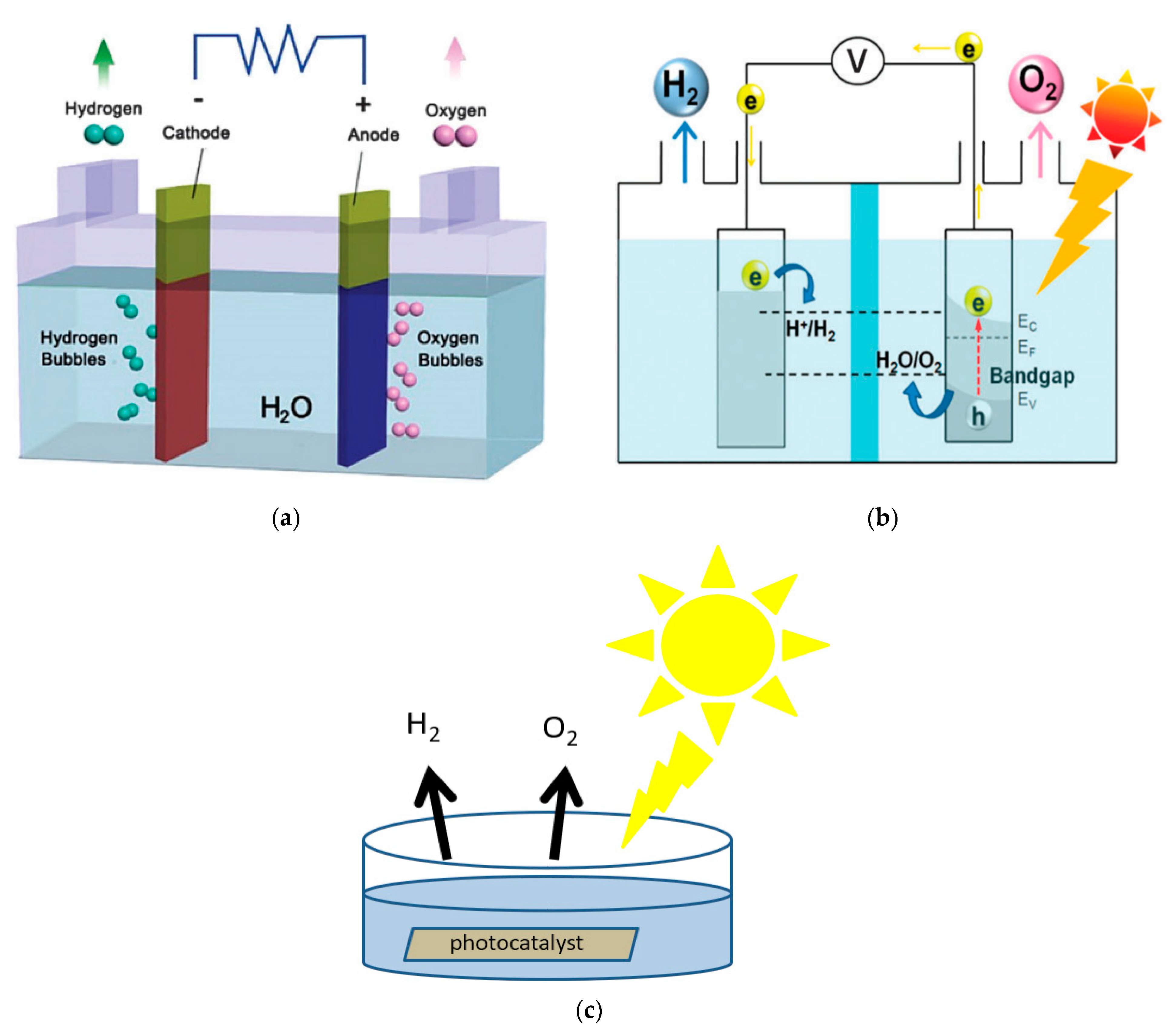
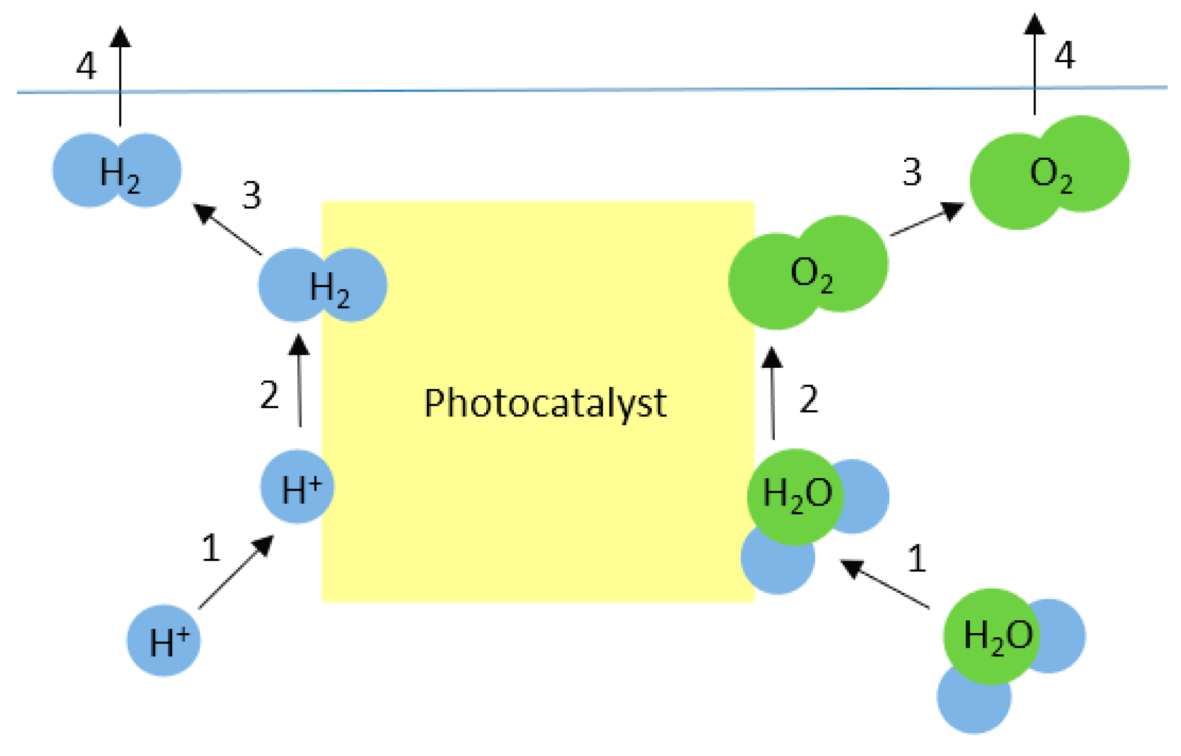
2. Mechanism of Photocatalytic Water Splitting
3. Factors Hindering the Efficient Water Splitting Process
3.1. Charge Recombination
3.2. Back Oxidation Reaction
3.3. Mass Transfer Limitation
4. Developments in TiO2-Related Nano Catalysts for Photocatalytic Water Splitting
4.1. Use of Nanostructures and Morphology Modulation
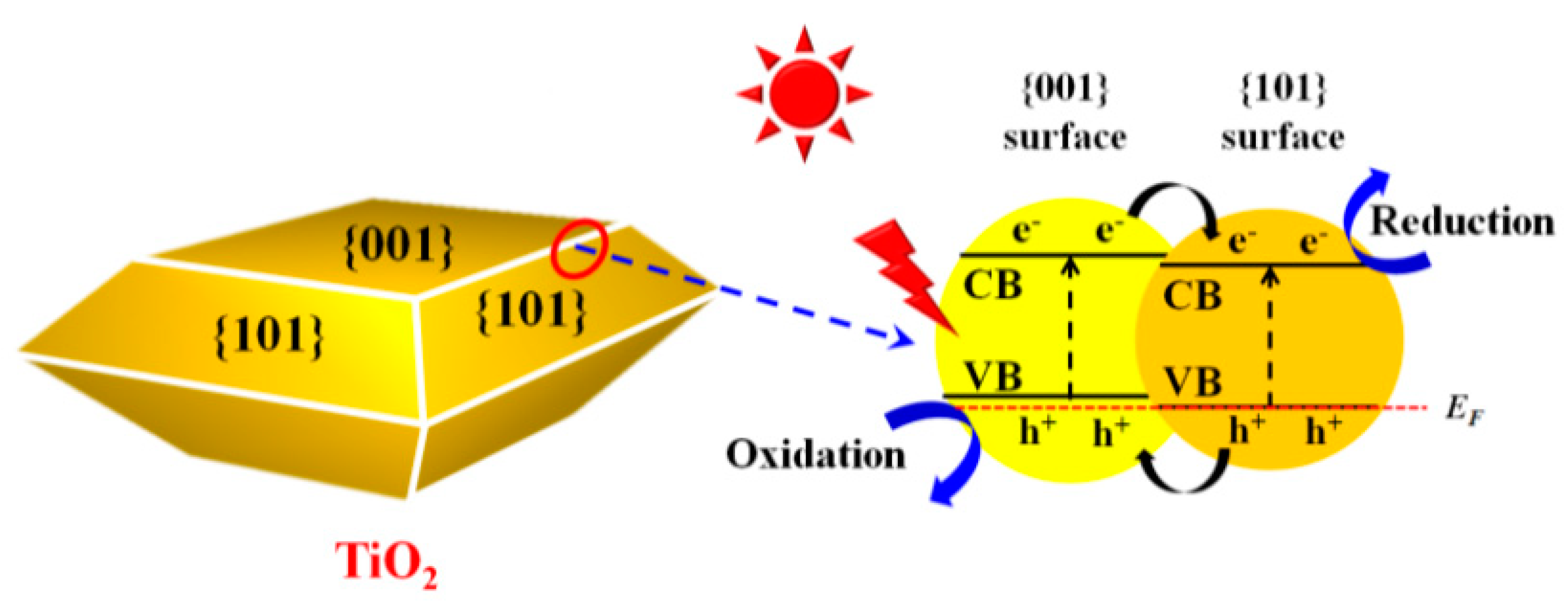
4.2. Modulation of Facets
4.3. Modulation of Defects
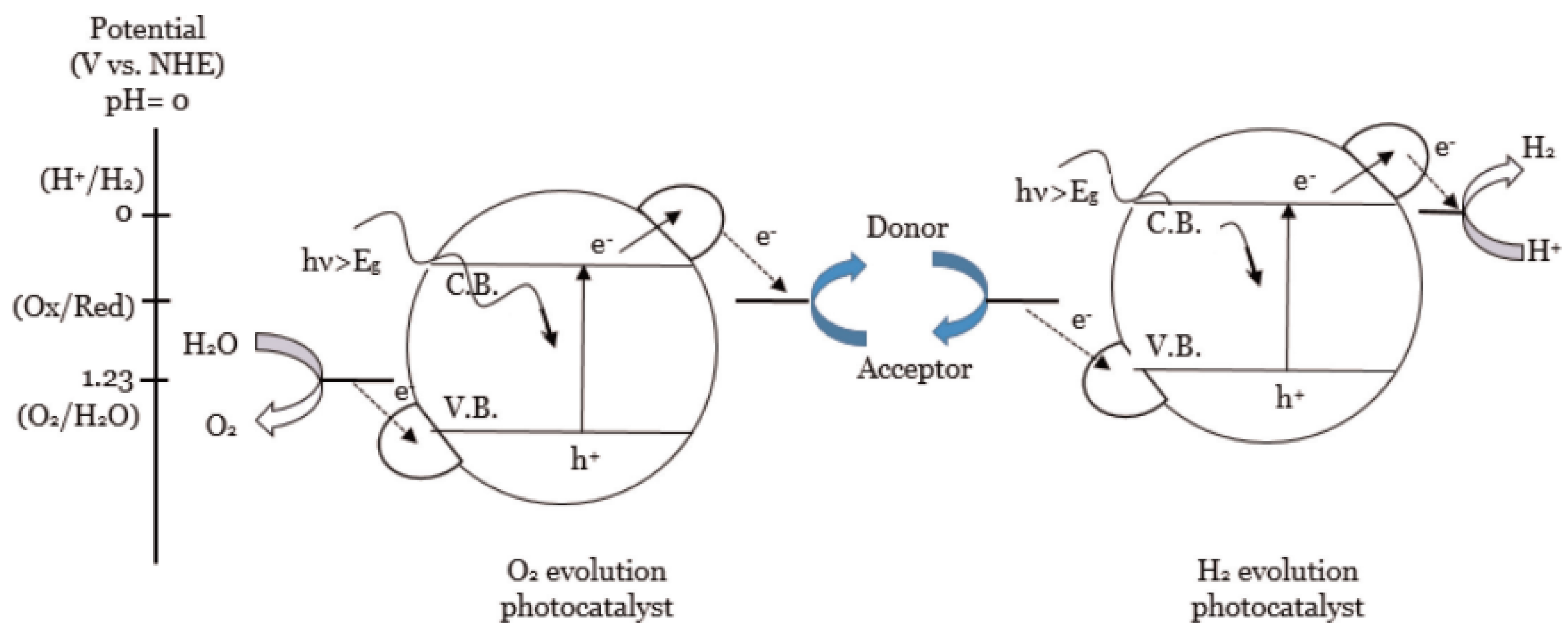
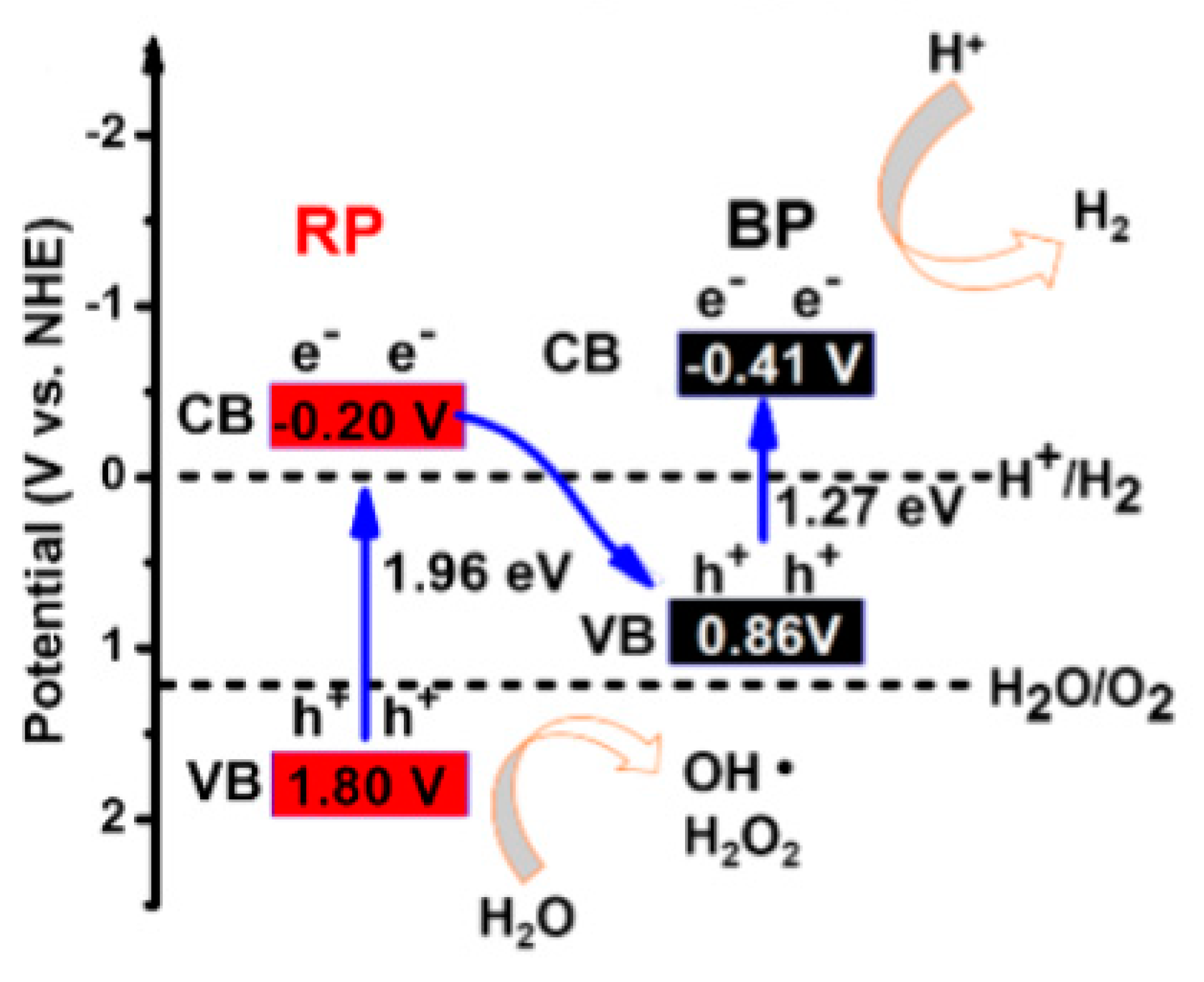
5. Z-Schemed Catalysts for Photocatalytic Water Splitting
6. Computational Approaches towards Nobel Metal-Free Catalysts for Photocatalytic Water Splitting
Janus MoSSe Monolayer as a Potential Photocatalyst for Water Splitting Applications
7. Conclusions
Author Contributions
Funding
Institutional Review Board Statement
Informed Consent Statement
Data Availability Statement
Acknowledgments
Conflicts of Interest
References
- Zou, X.; Zhang, Y. Noble Metal-Free Hydrogen Evolution Catalysts for Water Splitting. Chem. Soc. Rev. 2015, 44, 5148–5180. [Google Scholar] [CrossRef]
- Ipek, B.; Uner, D. On the Limits of Photocatalytic Water Splitting; IntechOpen: London, UK, 2019; ISBN 978-1-78985-429-9. [Google Scholar]
- Kalamaras, C.M.; Efstathiou, A.M. Hydrogen Production Technologies: Current State and Future Developments. Conf. Pap. Energy 2013, 2013, 690627. [Google Scholar] [CrossRef]
- Nikolaidis, P.; Poullikkas, A. A Comparative Overview of Hydrogen Production Processes. Renew. Sustain. Energy Rev. 2017, 67, 597–611. [Google Scholar] [CrossRef]
- Shiva Kumar, S.; Himabindu, V. Hydrogen Production by PEM Water Electrolysis—A Review. Mater. Sci. Energy Technol. 2019, 2, 442–454. [Google Scholar] [CrossRef]
- Rhodes, C.J. Solar Energy: Principles and Possibilities. Sci. Prog. 2010, 93, 37–112. [Google Scholar] [CrossRef]
- Kober, T.; Schiffer, H.-W.; Densing, M.; Panos, E. Global Energy Perspectives to 2060—WEC’s World Energy Scenarios 2019. Energy Strategy Rev. 2020, 31, 100523. [Google Scholar] [CrossRef]
- Chen, H.M.; Chen, C.K.; Liu, R.-S.; Zhang, L.; Zhang, J.; Wilkinson, D.P. Nano-Architecture and Material Designs for Water Splitting Photoelectrodes. Chem. Soc. Rev. 2012, 41, 5654. [Google Scholar] [CrossRef]
- Li, G.; Huang, J.; Xue, C.; Chen, J.; Deng, Z.; Huang, Q.; Liu, Z.; Gong, C.; Guo, W.; Cao, R. Facile Synthesis of Oriented Feather-like TiO2 Bundle Catalysts for Efficient Photocatalytic Water Splitting. Cryst. Growth Des. 2019, 19, 3584–3591. [Google Scholar] [CrossRef]
- Hu, Q.; Li, G.; Lan, H.; Li, J.; Hu, B.; Guo, W.; Huang, J.; Huang, X. Facile Coengineering of Oxygen Defects and Highly Active {110} Facets in TiO2 Nanorods for Efficient Water Splitting. Cryst. Growth Des. 2019, 19, 1680–1688. [Google Scholar] [CrossRef]
- Kong, X.; Xu, Y.; Cui, Z.; Li, Z.; Liang, Y.; Gao, Z.; Zhu, S.; Yang, X. Defect Enhances Photocatalytic Activity of Ultrathin TiO2 (B) Nanosheets for Hydrogen Production by Plasma Engraving Method. Appl. Catal. B Environ. 2018, 230, 11–17. [Google Scholar] [CrossRef]
- Wang, X.; Li, Z.; Shi, J.; Yu, Y. One-Dimensional Titanium Dioxide Nanomaterials: Nanowires, Nanorods, and Nanobelts. Chem. Rev. 2014, 114, 9346–9384. [Google Scholar] [CrossRef] [PubMed]
- De Angelis, F.; Di Valentin, C.; Fantacci, S.; Vittadini, A.; Selloni, A. Theoretical Studies on Anatase and Less Common TiO2 Phases: Bulk, Surfaces, and Nanomaterials. Chem. Rev. 2014, 114, 9708–9753. [Google Scholar] [CrossRef]
- Park, J.H.; Kim, S.; Bard, A.J. Novel Carbon-Doped TiO2 Nanotube Arrays with High Aspect Ratios for Efficient Solar Water Splitting. Nano Lett. 2005, 6, 24–28. [Google Scholar] [CrossRef] [PubMed]
- Hwang, Y.J.; Hahn, C.; Liu, B.; Yang, P. Photoelectrochemical Properties of TiO2 Nanowire Arrays: A Study of the Dependence on Length and Atomic Layer Deposition Coating. ACS Nano 2012, 6, 5060–5069. [Google Scholar] [CrossRef]
- Liu, J.; Wan, J.; Liu, L.; Yang, W.; Low, J.; Gao, X.; Fu, F. Synergistic Effect of Oxygen Defect and Doping Engineering on S-Scheme O-ZnIn2S4/TiO2-x Heterojunction for Effective Photocatalytic Hydrogen Production by Water Reduction Coupled with Oxidative Dehydrogenation. Chem. Eng. J. 2022, 430, 133125. [Google Scholar] [CrossRef]
- Balayeva, N.O.; Mamiyev, Z.; Dillert, R.; Zheng, N.; Bahnemann, D.W. Rh/TiO2-Photocatalyzed Acceptorless Dehydrogenation of N-Heterocycles upon Visible-Light Illumination. ACS Catal. 2020, 10, 5542–5553. [Google Scholar] [CrossRef]
- García-Muñoz, P.; Zussblatt, N.P.; Chmelka, B.F.; de la Peña O’Shea, V.A.; Fresno, F. Production of Hydrogen from Gas-Phase Ethanol Dehydrogenation over Iron-Grafted Mesoporous Pt/TiO2 Photocatalysts. Chem. Eng. J. 2022, 450, 138450. [Google Scholar] [CrossRef]
- Ren, L.; Zhu, W.; Li, Y.; Lin, X.; Xu, H.; Sun, F.; Lu, C.; Zou, J. Oxygen Vacancy-Rich 2D TiO2 Nanosheets: A Bridge toward High Stability and Rapid Hydrogen Storage Kinetics of Nano-Confined MgH2. Nano-Micro Lett. 2022, 14, 144. [Google Scholar] [CrossRef]
- Shao, Y.; Gao, H.; Tang, Q.; Liu, Y.; Liu, J.; Zhu, Y.; Zhang, J.; Li, L.; Hu, X.; Ba, Z. Ultra-Fine TiO2 Nanoparticles Supported on Three-Dimensionally Ordered Macroporous Structure for Improving the Hydrogen Storage Performance of MgH2. Appl. Surf. Sci. 2022, 585, 152561. [Google Scholar] [CrossRef]
- Zhang, Y.; Zhang, W.; Wei, X.; Yuan, Z.; Gao, J.; Guo, S.; Ren, H. Catalytic Effects of TiO2 on Hydrogen Storage Thermodynamics and Kinetics of the As-Milled Mg-Based Alloy. Mater. Charact. 2021, 176, 111118. [Google Scholar] [CrossRef]
- Zhang, Y.; Xing, Z.; Liu, X.; Li, Z.; Wu, X.; Jiang, J.; Li, M.; Zhu, Q.; Zhou, W. Ti3+ Self-Doped Blue TiO2(B) Single-Crystalline Nanorods for Efficient Solar-Driven Photocatalytic Performance. ACS Appl. Mater. Interfaces 2016, 8, 26851–26859. [Google Scholar] [CrossRef] [PubMed]
- Hou, H.; Yuan, Y.; Cao, S.; Yang, Y.; Ye, X.; Yang, W. CuInS2 Nanoparticles Embedded in Mesoporous TiO2 Nanofibers for Boosted Photocatalytic Hydrogen Production. J. Mater. Chem. C 2020, 8, 11001–11007. [Google Scholar] [CrossRef]
- Zuo, G.; Wang, Y.; Teo, W.L.; Xian, Q.; Zhao, Y. Direct Z-Scheme TiO2–ZnIn2S4 Nanoflowers for Cocatalyst-Free Photocatalytic Water Splitting. Appl. Catal. B Environ. 2021, 291, 120126. [Google Scholar] [CrossRef]
- Nguyen, T.T.; Cao, T.M.; Balayeva, N.O.; Pham, V.V. Thermal Treatment of Polyvinyl Alcohol for Coupling MoS2 and TiO2 Nanotube Arrays toward Enhancing Photoelectrochemical Water Splitting Performance. Catalysts 2021, 11, 857. [Google Scholar] [CrossRef]
- Mamiyev, Z.; Balayeva, N.O. Metal Sulfide Photocatalysts for Hydrogen Generation: A Review of Recent Advances. Catalysts 2022, 12, 1316. [Google Scholar] [CrossRef]
- Daulbayev, C.; Sultanov, F.; Bakbolat, B.; Daulbayev, O. 0D, 1D and 2D Nanomaterials for Visible Photoelectrochemical Water Splitting. A Review. Int. J. Hydrogen Energy 2020, 45, 33325–33342. [Google Scholar] [CrossRef]
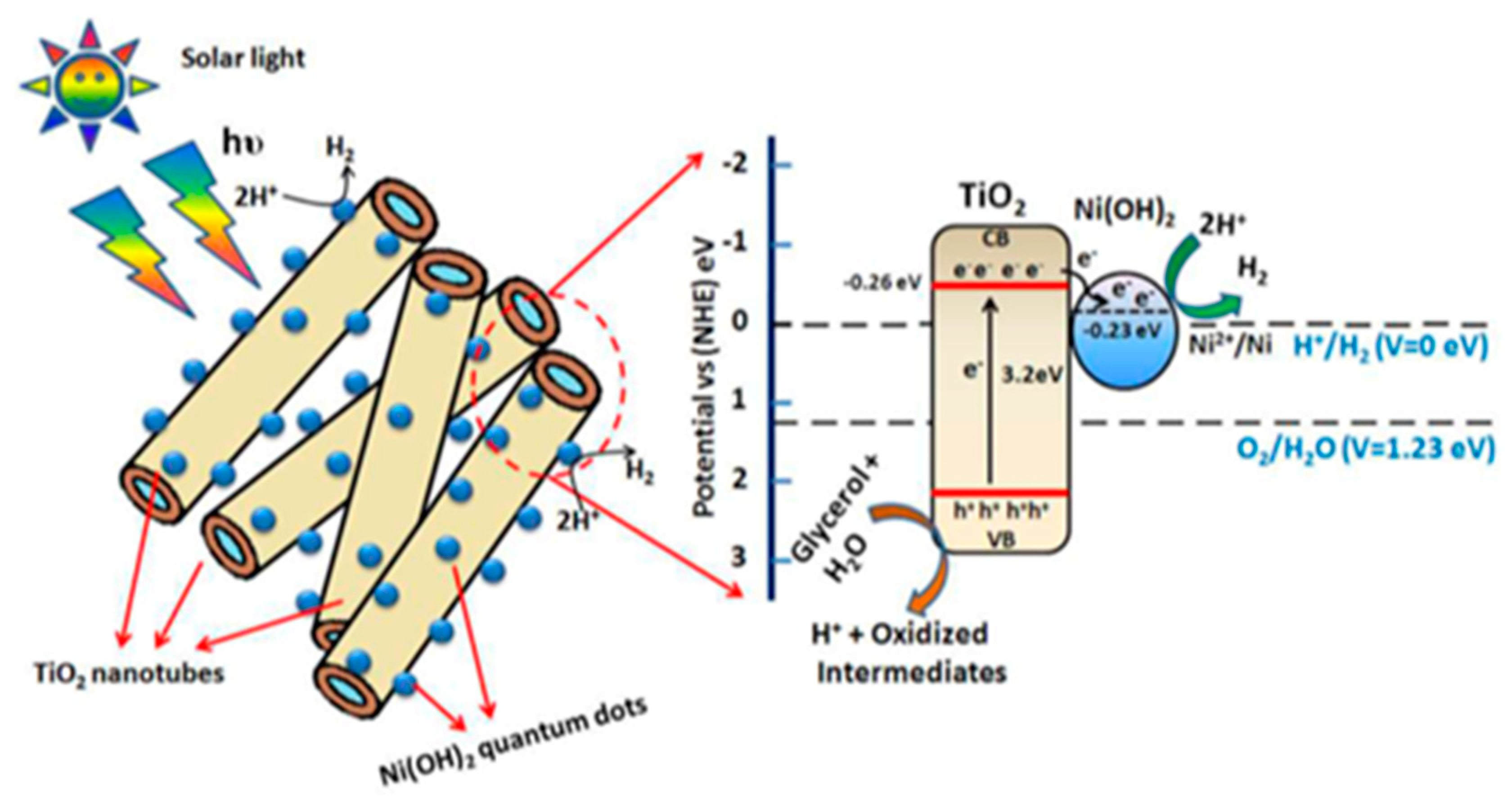
- Lakshmana Reddy, N.; Cheralathan, K.K.; Durga Kumari, V.; Neppolian, B.; Muthukonda Venkatakrishnan, S. Photocatalytic Reforming of Biomass Derived Crude Glycerol in Water: A Sustainable Approach for Improved Hydrogen Generation Using Ni(OH)2 Decorated TiO2 Nanotubes under Solar Light Irradiation. ACS Sustain. Chem. Eng. 2018, 6, 3754–3764. [Google Scholar] [CrossRef]
- Lakshmana Reddy, N.; Emin, S.; Valant, M.; Shankar, M.V. Nanostructured Bi2O3@TiO2 Photocatalyst for Enhanced Hydrogen Production. Int. J. Hydrogen Energy 2017, 42, 6627–6636. [Google Scholar] [CrossRef]
- Hu, W.; Zhou, W.; Zhang, K.; Zhang, X.; Wang, L.; Jiang, B.; Tian, G.; Zhao, D.; Fu, H. Facile Strategy for Controllable Synthesis of Stable Mesoporous Black TiO2 Hollow Spheres with Efficient Solar-Driven Photocatalytic Hydrogen Evolution. J. Mater. Chem. A 2016, 4, 7495–7502. [Google Scholar] [CrossRef]
- Wang, W.; Dong, J.; Ye, X.; Li, Y.; Ma, Y.; Qi, L. Heterostructured TiO2Nanorod@Nanobowl Arrays for Efficient Photoelectrochemical Water Splitting. Small 2016, 12, 1469–1478. [Google Scholar] [CrossRef]
- Zhang, H.; Liu, X.; Li, Y.; Sun, Q.; Wang, Y.; Wood, B.J.; Liu, P.; Yang, D.; Zhao, H. Vertically Aligned Nanorod-like RutileTiO2 Single Crystal Nanowire Bundles with Superior Electron Transport and Photoelectrocatalytic Properties. J. Mater. Chem. 2012, 22, 2465–2472. [Google Scholar] [CrossRef]
- Li, F.; Huang, Y.; Peng, H.; Cao, Y.; Niu, Y. Preparation and Photocatalytic Water Splitting Hydrogen Production of Titanium Dioxide Nanosheets. Int. J. Photoenergy 2020, 2020, 3617312. [Google Scholar] [CrossRef]
- Chen, J.S.; Tan, Y.L.; Li, C.M.; Cheah, Y.L.; Luan, D.; Madhavi, S.; Boey, F.Y.C.; Archer, L.A.; Lou, X.W. Constructing Hierarchical Spheres from Large Ultrathin Anatase TiO2 Nanosheets with Nearly 100% Exposed (001) Facets for Fast Reversible Lithium Storage. J. Am. Chem. Soc. 2010, 132, 6124–6130. [Google Scholar] [CrossRef]
- Mukhopadhyay, S.; Maiti, D.; Saha, A.; Devi, P.S. Shape Transition of TiO2 Nanocube to Nanospindle Embedded on Reduced Graphene Oxide with Enhanced Photocatalytic Activity. Cryst. Growth Des. 2016, 16, 6922–6932. [Google Scholar] [CrossRef]
- Diebold, U. The Surface Science of Titanium Dioxide. Surf. Sci. Rep. 2003, 48, 53–229. [Google Scholar] [CrossRef]
- Zhao, X.; Jin, W.; Cai, J.; Ye, J.; Li, Z.; Ma, Y.; Xie, J.; Qi, L. Shape- and Size-Controlled Synthesis of Uniform Anatase TiO2 Nanocuboids Enclosed by Active {100} and {001} Facets. Adv. Funct. Mater. 2011, 21, 3554–3563. [Google Scholar] [CrossRef]
- Liu, L.; Liu, Z.; Liu, A.; Gu, X.; Ge, C.; Gao, F.; Dong, L. Engineering the TiO2-Graphene Interface to Enhance Photocatalytic H2Production. ChemSusChem 2013, 7, 618–626. [Google Scholar] [CrossRef] [PubMed]
- Amano, F.; Prieto-Mahaney, O.-O.; Terada, Y.; Yasumoto, T.; Shibayama, T.; Ohtani, B. Decahedral Single-Crystalline Particles of Anatase Titanium(IV) Oxide with High Photocatalytic Activity. Chem. Mater. 2009, 21, 2601–2603. [Google Scholar] [CrossRef]
- Amano, F.; Yasumoto, T.; Prieto-Mahaney, O.-O.; Uchida, S.; Shibayama, T.; Ohtani, B. Photocatalytic Activity of Octahedral Single-Crystalline Mesoparticles of Anatase Titanium(Iv) Oxide. Chem. Commun. 2009, 2311. [Google Scholar] [CrossRef]
- Xing, M.-Y.; Yang, B.-X.; Yu, H.; Tian, B.-Z.; Bagwasi, S.; Zhang, J.-L.; Gong, X.-Q. Enhanced Photocatalysis by Au Nanoparticle Loading on TiO2 Single-Crystal (001) and (110) Facets. J. Phys. Chem. Lett. 2013, 4, 3910–3917. [Google Scholar] [CrossRef]
- Zheng, J.-Y.; Bao, S.-H.; Guo, Y.; Jin, P. Anatase TiO2 Films with Dominant {001} Facets Fabricated by Direct-Current Reactive Magnetron Sputtering at Room Temperature: Oxygen Defects and Enhanced Visible-Light Photocatalytic Behaviors. ACS Appl. Mater. Interfaces 2014, 6, 5940–5946. [Google Scholar] [CrossRef] [PubMed]
- Xu, J.; Xu, L.-F.; Li, Z.-Z.; Wang, J.-T.; Lin, Z.-S.; Liu, K.; Cao, Y.-G.; Selloni, A. Ab InitioStudy of Water Adsorption and Reactivity on the (211) Surface of Anatase TiO2. Phys. Rev. Appl. 2016, 5, 064001. [Google Scholar] [CrossRef]
- Xu, H.; Reunchan, P.; Ouyang, S.; Tong, H.; Umezawa, N.; Kako, T.; Ye, J. Anatase TiO2 Single Crystals Exposed with High-Reactive {111} Facets toward Efficient H2 Evolution. Chem. Mater. 2013, 25, 405–411. [Google Scholar] [CrossRef]
- Ma, X.; Dai, Y.; Guo, M.; Huang, B. Relative Photooxidation and Photoreduction Activities of the {100}, {101}, and {001} Surfaces of Anatase TiO2. Langmuir 2013, 29, 13647–13654. [Google Scholar] [CrossRef]
- Sajan, C.P.; Wageh, S.; Al-Ghamdi, A.A.; Yu, J.; Cao, S. TiO2 Nanosheets with Exposed {001} Facets for Photocatalytic Applications. Nano Res. 2015, 9, 3–27. [Google Scholar] [CrossRef]
- Zhang, A.-Y.; Wang, W.-Y.; Chen, J.-J.; Liu, C.; Li, Q.-X.; Zhang, X.; Li, W.-W.; Si, Y.; Yu, H.-Q. Epitaxial Facet Junctions on TiO2 Single Crystals for Efficient Photocatalytic Water Splitting. Energy Environ. Sci. 2018, 11, 1444–1448. [Google Scholar] [CrossRef]
- Zhou, X.; Liu, N.; Schmidt, J.; Kahnt, A.; Osvet, A.; Romeis, S.; Zolnhofer, E.M.; Marthala, V.R.R.; Guldi, D.M.; Peukert, W.; et al. Noble-Metal-Free Photocatalytic Hydrogen Evolution Activity: The Impact of Ball Milling Anatase Nanopowders with TiH2. Adv. Mater. 2016, 29, 1604747. [Google Scholar] [CrossRef] [PubMed]
- Niu, X.; Bai, X.; Zhou, Z.; Wang, J. Rational Design and Characterization of Direct Z-Scheme Photocatalyst for Overall Water Splitting from Excited State Dynamics Simulations. ACS Catal. 2020, 10, 1976–1983. [Google Scholar] [CrossRef]
- Su, T.; Shao, Q.; Qin, Z.; Guo, Z.; Wu, Z. Role of Interfaces in Two-Dimensional Photocatalyst for Water Splitting. ACS Catal. 2018, 8, 2253–2276. [Google Scholar] [CrossRef]
- Fu, C.-F.; Wu, X.; Yang, J. Material Design for Photocatalytic Water Splitting from a Theoretical Perspective. Adv. Mater. 2018, 30, 1802106. [Google Scholar] [CrossRef]
- Kim, J.S.; Kim, B.; Kim, H.; Kang, K. Recent Progress on Multimetal Oxide Catalysts for the Oxygen Evolution Reaction. Adv. Energy Mater. 2018, 8, 1702774. [Google Scholar] [CrossRef]
- Wang, L.; Zheng, X.; Chen, L.; Xiong, Y.; Xu, H. Van Der Waals Heterostructures Comprised of Ultrathin Polymer Nanosheets for Efficient Z-Scheme Overall Water Splitting. Angew. Chem. Int. Ed. 2018, 57, 3454–3458. [Google Scholar] [CrossRef] [PubMed]
- Di, T.; Xu, Q.; Ho, W.; Tang, H.; Xiang, Q.; Yu, J. Review on Metal Sulphide-Based Z-Scheme Photocatalysts. ChemCatChem 2019, 11, 1394–1411. [Google Scholar] [CrossRef]
- Mohanty, B.; Ghorbani-Asl, M.; Kretschmer, S.; Ghosh, A.; Guha, P.; Panda, S.K.; Jena, B.; Krasheninnikov, A.V.; Jena, B.K. MoS2 Quantum Dots as Efficient Catalyst Materials for the Oxygen Evolution Reaction. ACS Catal. 2018, 8, 1683–1689. [Google Scholar] [CrossRef]
- Di, J.; Chen, C.; Yang, S.-Z.; Ji, M.; Yan, C.; Gu, K.; Xia, J.; Li, H.; Li, S.; Liu, Z. Defect Engineering in Atomically-Thin Bismuth Oxychloride towards Photocatalytic Oxygen Evolution. J. Mater. Chem. A 2017, 5, 14144–14151. [Google Scholar] [CrossRef]
- Wei, T.; Zhu, Y.-N.; An, X.; Liu, L.-M.; Cao, X.; Liu, H.; Qu, J. Defect Modulation of Z-Scheme TiO2/Cu2O Photocatalysts for Durable Water Splitting. ACS Catal. 2019, 9, 8346–8354. [Google Scholar] [CrossRef]
- Paracchino, A.; Laporte, V.; Sivula, K.; Grätzel, M.; Thimsen, E. Highly Active Oxide Photocathode for Photoelectrochemical Water Reduction. Nat. Mater. 2011, 10, 456–461. [Google Scholar] [CrossRef] [PubMed]
- Zhang, N.; Li, X.; Ye, H.; Chen, S.; Ju, H.; Liu, D.; Lin, Y.; Ye, W.; Wang, C.; Xu, Q.; et al. Oxide Defect Engineering Enables to Couple Solar Energy into Oxygen Activation. J. Am. Chem. Soc. 2016, 138, 8928–8935. [Google Scholar] [CrossRef]
- Liu, F.; Shi, R.; Wang, Z.; Weng, Y.; Che, C.; Chen, Y. Direct Z-Scheme Hetero-Phase Junction of Black/Red Phosphorus for Photocatalytic Water Splitting. Angew. Chem. 2019, 131, 11917–11921. [Google Scholar] [CrossRef]
- Guo, H.-L.; Du, H.; Jiang, Y.-F.; Jiang, N.; Shen, C.-C.; Zhou, X.; Liu, Y.-N.; Xu, A.-W. Artificial Photosynthetic Z-Scheme Photocatalyst for Hydrogen Evolution with High Quantum Efficiency. J. Phys. Chem. C 2016, 121, 107–114. [Google Scholar] [CrossRef]
- Shi, J.; Li, S.; Wang, F.; Li, Y.; Gao, L.; Zhang, X.; Lu, J. In Situ Topotactic Fabrication of Direct Z-Scheme 2D/2D ZnO/ZnxCd1−xS Single Crystal Nanosheet Heterojunction for Efficient Photocatalytic Water Splitting. Catal. Sci. Technol. 2018, 8, 6458–6467. [Google Scholar] [CrossRef]
- Shi, L.; Li, Q.; Ling, C.; Zhang, Y.; Ouyang, Y.; Bai, X.; Wang, J. Metal-Free Electrocatalyst for Reducing Nitrogen to Ammonia Using a Lewis Acid Pair. J. Mater. Chem. A 2019, 7, 4865–4871. [Google Scholar] [CrossRef]
- Liu, C.; Li, Q.; Wu, C.; Zhang, J.; Jin, Y.; MacFarlane, D.R.; Sun, C. Single-Boron Catalysts for Nitrogen Reduction Reaction. J. Am. Chem. Soc. 2019, 141, 2884–2888. [Google Scholar] [CrossRef] [PubMed]
- Ma, X.; Yong, X.; Jian, C.; Zhang, J. Transition Metal-Functionalized Janus MoSSe Monolayer: A Magnetic and Efficient Single-Atom Photocatalyst for Water-Splitting Applications. J. Phys. Chem. C 2019, 123, 18347–18354. [Google Scholar] [CrossRef]
- Liu, X.; Iocozzia, J.; Wang, Y.; Cui, X.; Chen, Y.; Zhao, S.; Li, Z.; Lin, Z. Noble Metal—Metal Oxide Nanohybrids with Tailored Nanostructures for Efficient Solar Energy Conversion, Photocatalysis and Environmental Remediation. Energy Environ. Sci. 2017, 10, 402–434. [Google Scholar] [CrossRef]
- Ma, X.; Wu, X.; Wang, H.; Wang, Y. A Janus MoSSe Monolayer: A Potential Wide Solar-Spectrum Water-Splitting Photocatalyst with a Low Carrier Recombination Rate. J. Mater. Chem. A 2018, 6, 2295–2301. [Google Scholar] [CrossRef]
- Xia, C.; Xiong, W.; Du, J.; Wang, T.; Peng, Y.; Li, J. Universality of Electronic Characteristics and Photocatalyst Applications in the Two-Dimensional Janus Transition Metal Dichalcogenides. Phys. Rev. B 2018, 98, 165424. [Google Scholar] [CrossRef]
- Zhu, H.-Y.; Jiang, R.; Fu, Y.-Q.; Li, R.-R.; Yao, J.; Jiang, S.-T. Novel Multifunctional NiFe2O4/ZnO Hybrids for Dye Removal by Adsorption, Photocatalysis and Magnetic Separation. Appl. Surf. Sci. 2016, 369, 1–10. [Google Scholar] [CrossRef]
- Peramune, D.; Manatunga, D.C.; Dassanayake, R.S.; Premalal, V.; Liyanage, R.N.; Gunathilake, C.; Abidi, N. Recent Advances in Biopolymer-Based Advanced Oxidation Processes for Dye Removal Applications: A Review. Environ. Res. 2022, 215, 114242. [Google Scholar] [CrossRef]


| Nanomaterial | Enhancement Technique | Hydrogen Yield | Light Source Used | Remarks | Reference |
|---|---|---|---|---|---|
| TiO2 nanotubes with Ni(OH)2 co-catalyst. | Modification of nanotubes with quantum dots by wet impregnation. | 4.71 mmol h−1 g−1 | Natural sunlight. | 5% V/V crude glycerol solution was used. | [28] |
| TiO2 nanotubes. | Non-modified nanotubes prepared by hydrothermal method. | 0.39 mmol h−1 g−1 | Natural sunlight. | 5% V/V crude glycerol solution was used. | [28] |
| TiO2 nanotubes with Ni(OH)2 co-catalyst. | Modification of nanotubes with quantum dots by wet impregnation. | 45.57 mmol h−1 g−1 | Natural sunlight. | 5% V/V pure glycerol solution was used. | [28] |
| TiO2 nanostructure with Bi2O3 co-catalyst. | Modification of nanostructure with quantum dots by wet impregnation. | 26.02 mmol h−1 g−1 | Sun light. | 5% V/V glycerol solution. | [29] |
| TiO2 nanostructure. | Non-modified nanostructure prepared by hydrothermal method. | 4.20 mmol h−1 g−1 | Sun light. | 5% V/V glycerol solution. | [29] |
| Mesoporous black TiO2 hollow spheres. | High crystallinity, integrated hollow structure, Ti3+ in frameworks and surface disorders obtained through template-free solvothermal method and an amine molecule reflux-encircling process followed by high-temperature hydrogenation. | 241 mmol h−1 0.1 g−1 | AM 1.5 solar power system. | 20% V/V methanol solution. | [30] |
| Crushed spheres of mesoporous black TiO2. | 106 mmol h−1 0.1 g−1 | AM 1.5 solar power system. | 20% V/V methanol solution. | [30] | |
| Black TiO2 nanoparticles. | Hydrogenation of commercial anatase TiO2 under same condition as previous. | 118 mmol h−1 0.1 g−1 | AM 1.5 solar power system. | 20% V/V methanol solution. | [30] |
| TiO2 nanorods on quartz glass substrate. | Ti3+/Ov anatase nanorods exposed with a large percentage of {110} lateral surfaces on quartz glass substrate obtained by one-step technology of radio frequency (RF) magnetron sputtering. | 14.35 mmol m−2 h−1 | 300 W Xe lamp. | 10% V/V methanol solution. | [10] |
| TiO2 nanorods on quartz glass substrate. | Ti3+/Ov anatase nanorods exposed with a large percentage of {110} lateral surfaces on quartz glass substrate obtained by one-step technology of radio frequency (RF) magnetron sputtering. | 0.0995 mmol m−2 h−1 | 300 W Xe lamp. | Without any sacrificial agent. | [10] |
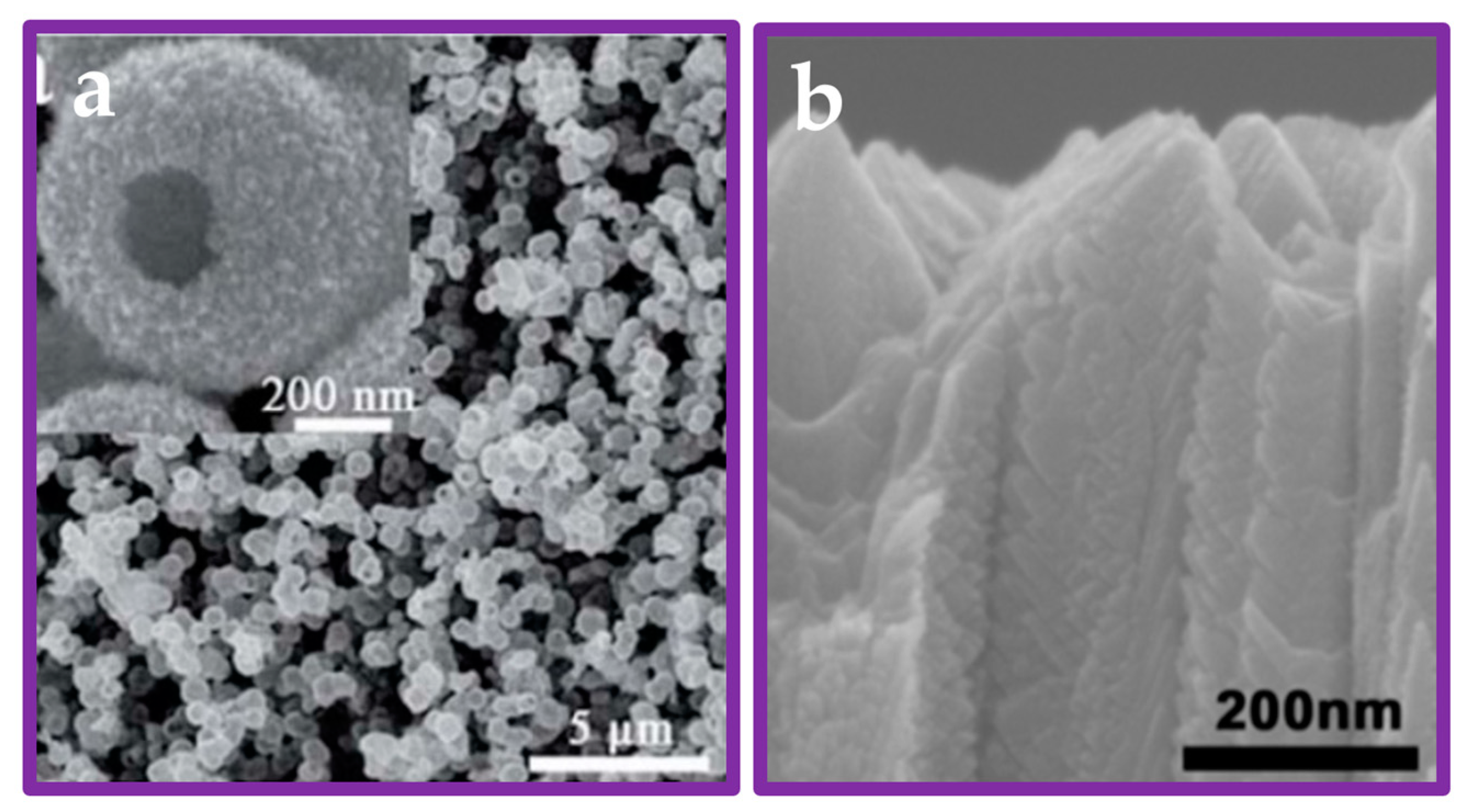
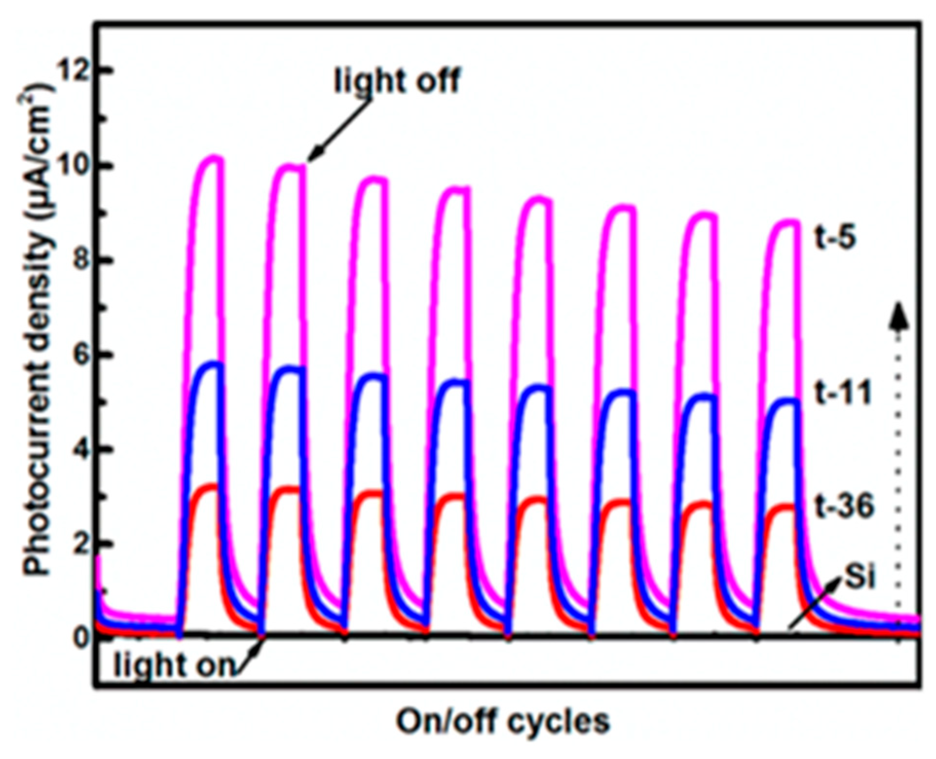
| Feather-like TiO2 nanosheet bundle on Si substrate. | Feather-like TiO2 nanosheet bundle catalyst with a highly (112) preferred orientation on a Si substrate using a facile magnetron sputtering method. | 44.74 mmol m−2 h−1 | 300 W xenon lamp. | 10% V/V methanol solution. | [9] |
| Feather-like TiO2 nanosheet bundle on Si substrate. | Feather-like TiO2 nanosheet bundle catalyst with a highly (112) preferred orientation on a Si substrate using a facile magnetron sputtering method. | 0.86 mmol m−2 h−1 | 300 W xenon lamp. | Pure water. | [9] |
| Feather-like TiO2 nanosheet bundle on SiO2 substrate. | Feather-like TiO2 nanosheet bundle catalyst with a highly (112) preferred orientation on a SiO2 substrate using a facile magnetron sputtering method. | 31.69 mmol m−2 h−1 | 300 W xenon lamp. | 10% V/V methanol solution. | [9] |
| TiO2 (B) nanosheets. | TiO2 (B) nanosheets with defects of O vacancy and Ti3+ in the surface and bulk through the ambient-temperature plasma engraving treatment. | 0.16 mmol h−1 | 300 W xenon arc lamp with an AM 1.5 filter. | Not specified. | [11] |
| Pristine TiO2 (B) nanosheets. | Non-modified pristine TiO2 (B) nanosheets. | 0.096 mmol h−1 | 300 W xenon arc lamp with an AM 1.5 filter. | Not specified. | [11] |
| TiO2 nanosheet. | TiO2 nanosheets synthesized by hydrothermal calcination. | 0.27 mmol h−1 | Ultraviolet lamp. | 3% V/V methanol in deionized water and temperature of 10 °C. | [33] |
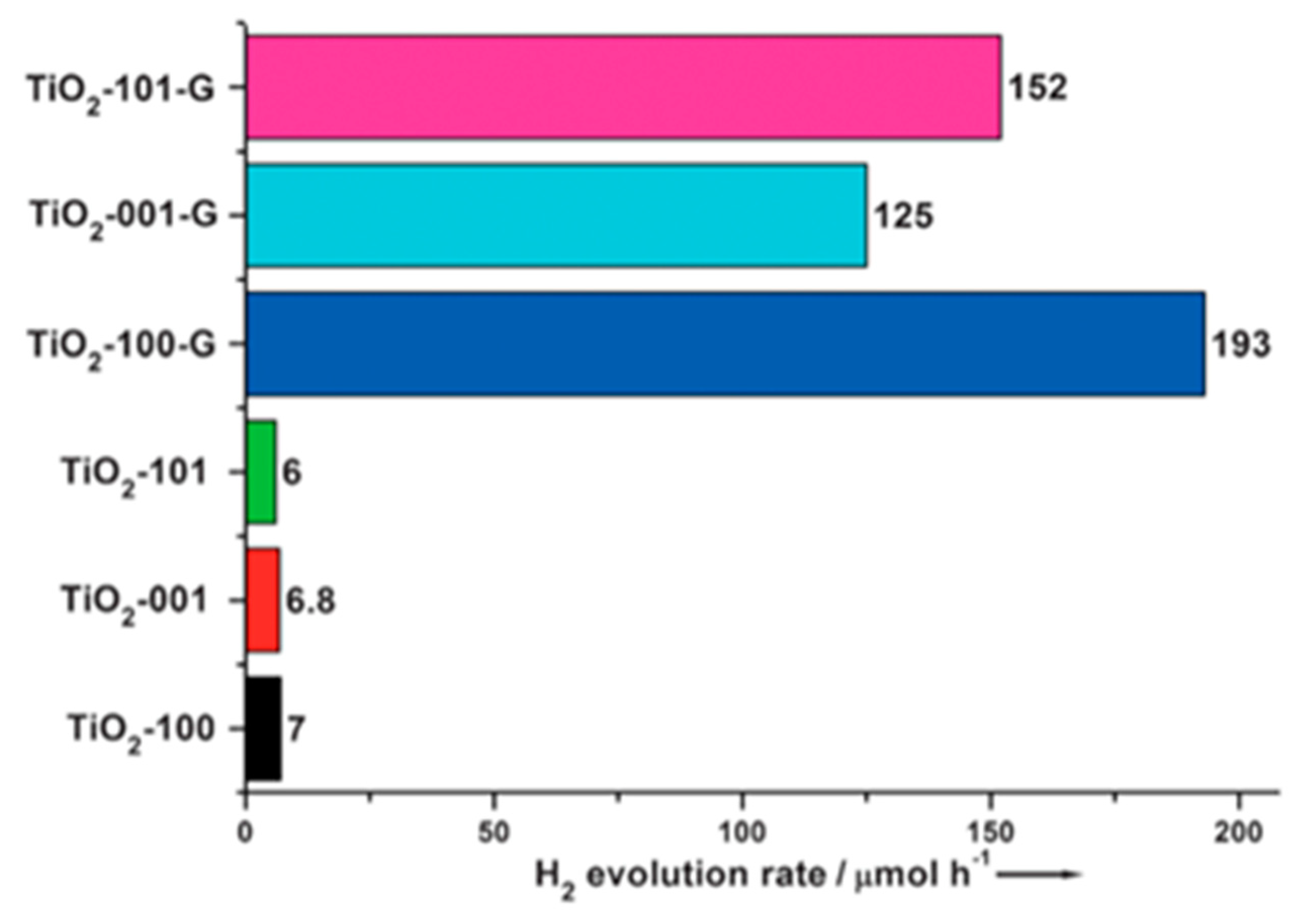
| TiO2 nanocrystals. | Exposure of {101} facets in nanocrystals. | 0.006 mmol h−1 | 300 W Hg lamp with a wavelength of approximately 365 nm. | 20% V/V methanol solution. | [38] |
| TiO2 nanocrystals. | Exposure of {001} facets in nanocrystals. | 0.0068 mmol h−1 | 300 W Hg lamp with a wavelength of approximately 365 nm. | 20% V/V methanol solution. | [38] |
| TiO2 nanocrystals. | Exposure of {100} facets in nanocrystals. | 0.007 mmol h−1 | 300 W Hg lamp with a wavelength of approximately 365 nm. | 20% V/V methanol solution. | [38] |
| TiO2-graphenenanocomposite. | Exposure of {101} facets in nanocrystals in the composite by anion-assisted method. | 0.152 mmol h−1 | 300 W Hg lamp with a wavelength of approximately 365 nm. | 20% V/V methanol solution. | [38] |
| TiO2-graphenenanocomposite. | Exposure of {001} facets in nanocrystals in the composite by anion-assisted method. | 0.125 mmol h−1 | 300 W Hg lamp with a wavelength of approximately 365 nm. | 20% V/V methanol solution. | [38] |
| TiO2-graphenenanocomposite. | Exposure of {100} facets in nanocrystals in the composite by anion-assisted method. | 0.193 mmol h−1 | 300 W Hg lamp with a wavelength of approximately 365 nm. | 20% V/V methanol solution. | [38] |
| TiO2 single crystals. | Co-exposure of {001} and {101} facets of anatase TiO2 single crystals using solvothermal method. | 0.5 mmol h−1g−1 | 300W Xe lamp. | 20% V/V methanol solution. | [47] |
| Nanomaterial | Enhancement Techniques | Hydrogen Yield | Light Source Used | Remarks | Reference |
|---|---|---|---|---|---|
| Cu2O/TiO2 heterostructure. | Exposure of {101} facets and creation of oxygen vacancies in TiO2 by hydrogen thermal reduction. | 32.6 mmol h−1 g−1 | 300 W Xe lamp. | 10% V/V methanol solution. | [57] |
| Ultrathin nanosheet of black/red phosphorus. | Creation of hetero-phase junction between black and red phosphorus crystal lattices by one-step wet-chemistry method. | 0.33 mmol g−1 h−1 | White LED light source (20 × 10 W, λ > 420 nm). | Pure water without any sacrificial agent. | [60] |
| Ultrathin nanosheet of black/red phosphorus with CO as a co-catalyst. | Incorporation of Co to the hetero-phase junction between black and red phosphorus crystal lattices prepared by one-step wet-chemistry method. | 2.96 mmol g−1 h−1 | White LED light source (20 × 10 W, λ > 420 nm). | Pure water without any sacrificial agent. | [60] |
| ZnO1−x nanorods. | Creation of oxygen vacancies in ZnO1−x nanorods by hydrothermal treatment. | 0.098 mmol h−1 | Visible-light irradiation (λ > 420 nm). | 0.1 g of catalyst in 100 mL aqueous solution containing 0.1 M Na2S and 0.1 M Na2SO3. | [61] |
| Zn0.2Cd0.8S nanoparticles. | Creation of nanoparticles by precipitating in aqueous solution at room temperature. | 0.125 mmol h−1 | Visible-light irradiation (λ > 420 nm). | 0.1 g of catalyst in 100 mL aqueous solution containing 0.1 M Na2S and 0.1 M Na2SO3. | [61] |
| Mixture of ZnO1−x and Zn0.2Cd0.8S. | Mechanical mixing of above two nanomaterials. | 0.12 mmol h−1 | Visible-light irradiation (λ > 420 nm). | 0.1 g of catalyst in 100 mL aqueous solution containing 0.1 M Na2S and 0.1 M Na2SO3. | [61] |
| Commercial oxygen-vacancy-free ZnO coupled with Zn0.2Cd0.8S. | Annealing the mixture of ZnO and Zn0.2Cd0.8S to create the heterojunction. | 0.186 mmol h−1 | Visible-light irradiation (λ > 420 nm). | 0.1 g of catalyst in 100 mL aqueous solution containing 0.1 M Na2S and 0.1 M Na2SO3. | [61] |
| Nanocomposite with a ZnO1−x (10 wt%)/Zn0.2Cd0.8S heterojunction. | Annealing the mixture of ZnO1−x (10 wt%) and Zn0.2Cd0.8S to create the heterojunction. | 2.518 mmol h−1 | Visible-light irradiation (λ > 420 nm). | 0.1 g of catalyst in 100 mL aqueous solution containing 0.1 M Na2S and 0.1 M Na2SO3. | [61] |
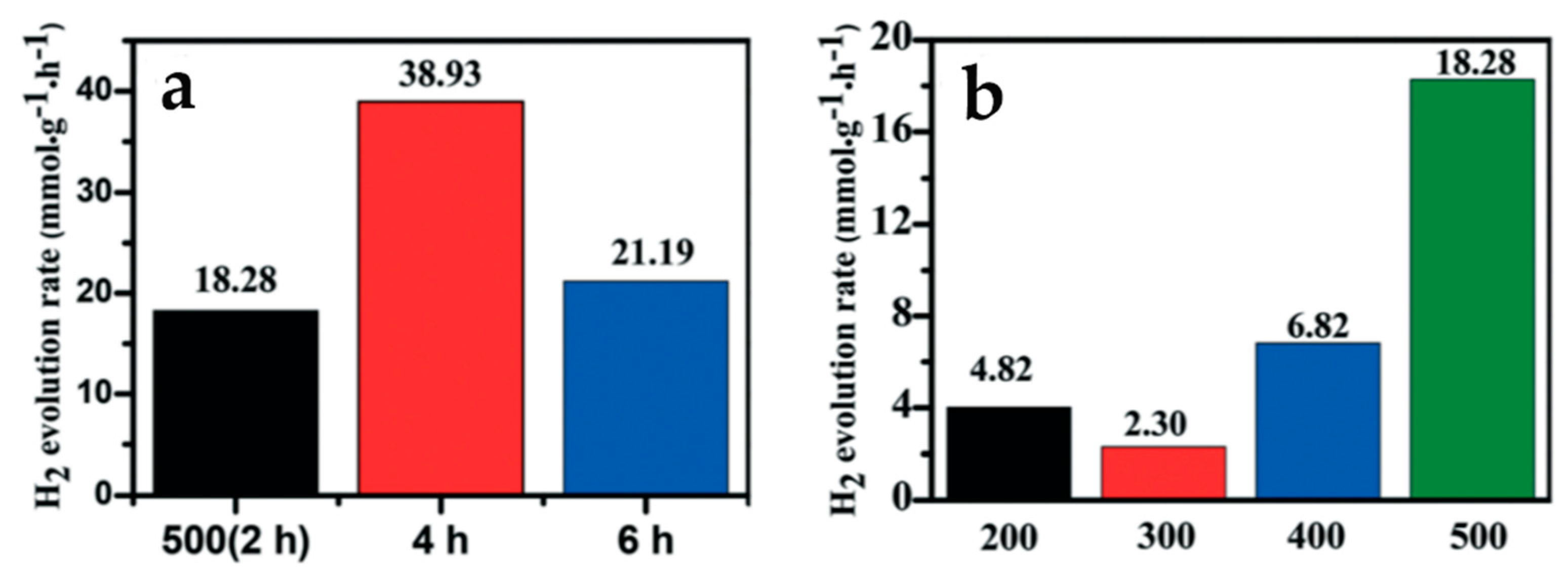
| ZnO/ZnxCd1−xS single crystal nanosheet heterojunction. | Synthesis of ZnxCd1−xS by sulfurization at 500 °C followed by oxidation for 2 h to create the heterojunction. | 18.28 mmol g−1 h−1 | 300 W xenon lamp with 420 nm optical cut-off filter. | 100 mL aqueous solution containing 0.1 mol l−1 Na2S/Na2SO3. | [62] |
| ZnO/ZnxCd1−xS single crystal nanosheet heterojunction. | Synthesis of ZnxCd1−xS by sulfurization at 500 °C followed by oxidation for 4 h to create the heterojunction. | 38.93 mmol g−1 h−1 | 300 W xenon lamp with 420 nm optical cut-off filter. | 100 mL aqueous solution containing 0.1 mol l−1 Na2S/Na2SO3. | [62] |
| ZnO/ZnxCd1−xS single crystal nanosheet heterojunction. | Synthesis of ZnxCd1−xS by sulfurization at 500 °C followed by oxidation for 6 h to create the heterojunction. | 21.19 mmol g−1 h−1 | 300 W xenon lamp with 420 nm optical cut-off filter. | 100 mL aqueous solution containing 0.1 mol l−1 Na2S/Na2SO3. | [62] |
Disclaimer/Publisher’s Note: The statements, opinions and data contained in all publications are solely those of the individual author(s) and contributor(s) and not of MDPI and/or the editor(s). MDPI and/or the editor(s) disclaim responsibility for any injury to people or property resulting from any ideas, methods, instructions or products referred to in the content. |
© 2023 by the authors. Licensee MDPI, Basel, Switzerland. This article is an open access article distributed under the terms and conditions of the Creative Commons Attribution (CC BY) license (https://creativecommons.org/licenses/by/4.0/).
Share and Cite
Dahanayake, A.; Gunathilake, C.A.; Pallegedara, A.; Jayasinghe, P. Recent Developments in Noble Metal-Free Catalysts for a Photocatalytic Water Splitting Process—A Review. J. Compos. Sci. 2023, 7, 64. https://doi.org/10.3390/jcs7020064
Dahanayake A, Gunathilake CA, Pallegedara A, Jayasinghe P. Recent Developments in Noble Metal-Free Catalysts for a Photocatalytic Water Splitting Process—A Review. Journal of Composites Science. 2023; 7(2):64. https://doi.org/10.3390/jcs7020064
Chicago/Turabian StyleDahanayake, Ama, Chamila A. Gunathilake, Achala Pallegedara, and Piumal Jayasinghe. 2023. "Recent Developments in Noble Metal-Free Catalysts for a Photocatalytic Water Splitting Process—A Review" Journal of Composites Science 7, no. 2: 64. https://doi.org/10.3390/jcs7020064
APA StyleDahanayake, A., Gunathilake, C. A., Pallegedara, A., & Jayasinghe, P. (2023). Recent Developments in Noble Metal-Free Catalysts for a Photocatalytic Water Splitting Process—A Review. Journal of Composites Science, 7(2), 64. https://doi.org/10.3390/jcs7020064