Article

Triboelectric Nanogenerators Based on Nanostructured Layers of Zinc Oxide Deposited on Carbon Fabric

by
Sergey I. Petrushenko
1,2,*,
Mateusz Fijalkowski
2,
Volodymyr R. Kopach
3,
Yevhenii M. Shepotko
3,
Kinga Adach
2,
Sergei V. Dukarov
1,
Volodymyr M. Sukhov
1,
Alina Fedonenko
1,
Alina L. Khrypunova
3 and
Natalia P. Klochko
3
1
School of Physics, V.N. Karazin Kharkiv National University, 4, Svobody Square, 61022 Kharkiv, Ukraine
2
Institute for Nanomaterials, Advanced Technologies and Innovation, Technical University of Liberec, 2, Studentska Str., 46117 Liberec, Czech Republic
3
Department of Micro- and Nanoelectronics, National Technical University “Kharkiv Polytechnic Institute”, 2, Kyrpychova Str., 61002 Kharkiv, Ukraine
*
Author to whom correspondence should be addressed.
J. Compos. Sci. 2023, 7(12), 496; https://doi.org/10.3390/jcs7120496
Submission received: 23 October 2023 / Revised: 3 November 2023 / Accepted: 28 November 2023 / Published: 30 November 2023
(This article belongs to the Section Nanocomposites)

Abstract

:
In this work, to obtain textile triboelectric layers for wearable flexible triboelectric nanogenerators (TENGs), we used two modes of growing nanostructured zinc oxide (ZnO) arrays on a carbon fabric (CF) using the automatic Successive Ionic Layer Adsorption and Reaction (SILAR) method. To produce a CF/ZnO_nr triboelectric textile with an array of intergrown short ZnO nanorods, we used a pre-coating of carbon fibers with ZnO seed layers. When the ZnO layer was fabricated by automatic SILAR on bare carbon fabric, we obtained the CF/ZnO_ns textile with an array of interconnected ZnO nanosheets 50–100 nm thick. As a proof of concept, we developed and tested two prototypes of flexible vertical contact–separation mode CF/ZnO_nr/PET/ITO and CF/ZnO_ns/PET/ITO TENGs, in which a gap was involuntarily formed between the smooth PET layer and the woven carbon textile coated with nanostructured ZnO films. In pressing tests with a force of ~5 N (pressure ~33 kPa), the CF/ZnO_ns/PET/ITO TENG created a higher open-circuit voltage up to 30 V and a higher maximum surface charge density of 1.3 μC/m2. In the successive press–release tests, this TENG showed an output voltage of 3.6 V, a current density of 1.47 μA/cm2, and a power density of 1.8 µW/cm2, confirming its effectiveness.

Graphical Abstract

1. Introduction

Biomechanical energy from human motions is the most abundant energy around us, and its harvesting could accelerate the development of wearable devices, and especially Internet of Things (IoT) sensors, the number of which is expected to reach more than 200 billion by 2025 [1]. Among mechanical energy harvesters, the most promising is the triboelectric nanogenerator (TENG) [1,2,3,4,5,6,7,8], which converts both voluntary and involuntary body motions into electricity through the coupling effects of contact electrification and electrostatic induction. The most common operating mode for energy harvesting is the vertical contact–separation of two dielectric materials, called triboelectric layers [6], and such contact electrification is often called triboelectrification. According to [1], triboelectrification is a phenomenon when electric charges move from one side of the TENG to the other if two different triboelectric layers come into contact due to external mechanical energy. As a result, triboelectrification induced opposing electrostatic charges on each surface of the triboelectric materials. Due to this, electrostatic charges of opposite signs arose on the conductive materials (electrodes) connected to these triboelectric layers. Then, caused by differences in electrical potentials, the charges of conductive materials tend to move from one side of the TENG to the other side along the external electrical circuit. Accordingly, an alternating current can flow through the load in the external circuit. With the help of a wearable TENG, the biomechanical energy between the foot and the floor during walking, as well as the energy of the joints (e.g., knees, elbows, and fingers), can be preferentially converted into electrical energy [1,2,3,4,5,6,7,8]. As stated in [5], the combination of flexible textiles with TENGs brings a novel insight into wearable functional electronics and cyber security in the era of the IoT. Flexible textile triboelectric layers are a low-cost and simple approach that is critical to realizing the full potential of TENGs [4]. Moreover, the morphology of textile materials potentially eliminates the need for complex TENG elements such as spacers. In addition, filling the fibers with triboelectric material makes it possible to increase the active area of the nanogenerator and, as a result, enhance its efficiency. Finally, the use of a flexible substrate allows the TENG to be integrated into clothing elements and significantly expands the scope of its use. According to [5], the distinguishing feature of this trend is the huge demand for wearable electronic devices/systems, totaling from billions to trillions, each of which requires a mobile power source. The integration of general-purpose TENG technology with smart fabrics brings new vitality and greater capabilities to the next generation of wearable electronics, personal healthcare, and human–computer interfaces [2,4,5,6,7,8]. In [2], commercially available metal-coated textile materials have been proposed as promising substrates for a wide range of wearable electronic device applications, including TENGs, due to their superior mechanical strength, light weight, flexibility, foldability, stretchability, good processability, and cost-effectiveness. But, as emphasized in [2,7,8], it remains a serious challenge to create reliable electrically conductive textiles due to the metal coating of ordinary fabrics, which will not have both chemical and physical damage. The excellent electrical conductivity and degradability exhibited by carbon nanotubes and grapheme-based materials make them promising candidates for textile TENG electrodes; however, they have not been widely promoted due to processing difficulties [7,8]. Conducting polymers, especially polystyrene sulfonate (PEDOT:PSS), provide important properties of textile TENGs such as flexibility, wear resistance, transparency, strong electron affinity, and good degradability [7,8], but their conductivity is lower than that of carbon-based materials and metal nanostructures [7]. At the same time, commercial carbon fabric (CF) is mechanically and chemically resistant like other fabrics, but its conductive carbon fibers are excellent conductors, allowing the textile triboelectric device to be inserted into specific areas of normal clothing and connect the conductive carbon fibers to an external electrical load [9,10,11,12]. Recently, various polymer and composite triboelectric materials have been used in textile TENGs [5,6,7]. Among them are Dacron textiles coated with polytetrafluoroethylene [5], Chinlon coated with polydimethylsiloxane [6], triboelectric textiles with a layer of black phosphorus nanoparticles and a cellulose-based coating for hydrophobic protection [6], cotton textiles coated with polyaniline [6], nylon fabric with a chitosan–glycerol composite film [7], and textiles coated with arrays of TiO2 nanotubes [7]. In [2,3,4], textile substrates were used for the chemical growth of nanostructured zinc oxide (ZnO) layers, which have mechanical strength along with high piezoelectric and triboelectric properties. The authors of [10,11,12,13,14] deposited arrays of ZnO nanostructures, such as nanoflowers [10], nanowires [12], and nanorods [11,13,14], onto carbon fabric using hydrothermal synthesis [10,11,12,13], as well as using combined atomic layer deposition and hydrothermal methods [14]. In this work, to obtain textile triboelectric layers of flexible TENGs, we used two modes of growing nanostructured ZnO arrays on a commercial CF using another hydrochemical method, namely the automatic Successive Ionic Layer Adsorption and Reaction (SILAR) method. Unlike the widely used hydrothermal method, the SILAR method is carried out at atmospheric pressure and moderate temperatures. Moreover, since in the SILAR method the working area is not limited by the volume of the autoclave, production can be scaled up. The automatic SILAR method, depending on the deposition mode, made it possible to create CF/ZnO materials that differ from each other in the morphology and composition of nanostructured ZnO layers. One triboelectric material was composed of multidirectional intergrown short ZnO nanorods (CF/ZnO_nr), while the second contained arrays of ZnO nanosheets (CF/ZnO_ns). As a proof of concept, we developed and tested two flexible TENG prototypes that combine the advantages of autonomy, material availability, design simplicity, low cost, and ease of fabrication. These TENGs were based on the CF/ZnO_nr and CF/ZnO_ns triboelectric textiles, respectively.

2. Materials and Methods

To create a CF/ZnO textile triboelectric material, we purchased a plain woven carbon fabric (Havel COMPOSITES CZ Ltd., Svésedlice, Czech Republic). Two pieces of carbon fabric with an active area of 2.5 cm × 5 cm each were used as substrates. The CF was initially cleaned by soaking overnight in a 10% aqueous solution of Elma lab clean A20sf (ELC A20sf, Elma Schmidbauer, Germany) surfactant-free cleaning concentrate. After that, the CF substrates were sequentially washed in a stream of distilled water, acetone, and ethanol. Then, before deposition of zinc oxide by SILAR, we pre-coated the CF with a ZnO seed layer to obtain the CF/ZnO_nr triboelectric material. To prepare the CF/ZnO_ns triboelectric material, a ZnO layer was deposited on a bare CF using a similar SILAR deposition method. When preparing the ZnO seed layer using the immersion method, a piece of CF was dipped for 30 s in an aqueous solution of the zinc tetraamine complex [Zn(NH3)4]2+, obtained by dissolving 0.05 M ZnO in an ammonia solution (NH4OH) at pH 10.3. Then, the CF substrate was dried in a stream of hot air. This process was repeated 10 times to obtain a ZnO seed layer uniformly covering the carbon fibers. To deposit a nanostructured ZnO film on the carbon fabric using the automatic SILAR method, an aqueous solution of zinc sulfate (1 M ZnSO4) and NH4OH was used as a cationic precursor. It was prepared via the gradual addition of 25% NH4OH to the ZnSO4 solution. Initially, a Zn(OH)2 precipitate formed, but in an excess of ammonia (at pH 12.1), it turned into a colorless transparent zinc tetraamine complex [Zn(NH3)4]2+. Hot (85–90 °C) distilled water was used as an anionic precursor in this SILAR process. The automatic SILAR method adopted a versatile numerical control motorized platform to ensure the scalability of the deposition process and achieve good reproducibility of the nanostructured ZnO layers. Such platforms are widely used in conventional commercial 3D printers. All stages of the SILAR method were programmed using g-code, the reproducibility of the CF immersion speed, and the time of each deposition stage was ensured with an error of <0.1%. One growth cycle of the SILAR deposition process consisted of the following three stages. The first step involved immersing the CF substrate in the cationic precursor for 10 s. The second step consisted of immersing it in hot distilled water while stirring with a magnetic stirrer at 100 rpm for 10 s. The third step was its washing in distilled water at room temperature for 5 s to remove excess ions and weakly bound particles from the surface. Thus, CF/ZnO_nr and CF/ZnO_ns samples were obtained in 25 SILAR cycles.
The morphology and chemical composition of the CF/ZnO_nr and CF/ZnO_ns triboelectric textiles were studied via scanning electron microscopy (SEM) and energy-dispersive X-ray spectroscopy (EDS), respectively. To perform this, we used a Zeiss ULTRA Plus SEM (ZEISS, Germany) instrument with an in-lens secondary electron detector objective equipped with an OXFORD X-Max 20 EDS (Oxford Instruments, UK) detector. To create EDS maps, we combined SEM imaging capabilities with EDS X-ray measurements.
Raman spectroscopy has been used for qualitative and quantitative studies of electron–phonon interaction in nanostructured ZnO films in CF/ZnO_nr and CF/ZnO_ns samples because it is sensitive to lattice distortions, crystal defects, and phase transformations [13,15,16,17,18,19,20]. The vibrational phonon modes of the nanostructured ZnO layers were characterized using a Raman microscope (Thermofisher Nicolet DXR Microscope, Thermo Fisher Scientific Inc., Waltham, MA, USA) with a solid-state diode green laser with an excitation wavelength of 532 nm and a power of 10 mW. Raman spectra were obtained at room temperature in backscattering geometry; they reflected the multidirectional scattering of phonons from a laser spot of ~2.1 μm in size. The Raman signal was integrated over 1 s with 100 exposures for each sample. Signal intensity, peak width (full width at half maximum, FWHM), and position (Raman shift frequency) were used as a measure of the crystalline quality of ZnO.
In this work, a flexible wearable TENG prototype of the most common vertical contact–separation mode with a two-electrode configuration was developed and tested as a proof of concept. It was a stack of two triboelectric parts. The textile tribopositive part at the bottom was the nanostructured layer of zinc oxide deposited by SILAR on the conductive carbon fabric that acted as the bottom electrode. The top tribonegative part of the TENG consisted of a flexible, high-electron-affinity polyethylene terephthalate (PET) thin-film tape coated with a conductive indium tin oxide (ITO) layer that acted as the top electrode. Here, we used a commercial PET/ITO tape from MSE Supplies LLC (US), in which a PET film with a thickness d1 of 175 μm was coated by a thin ITO layer with a sheet resistance of 6–10 Ω/sq. The design feature of this TENG is its simplicity due to the absence of a specially designed spacer that must provide an air gap between the upper and lower triboelectric layers. This gap in our TENG design spontaneously formed between the smooth PET layer and the woven textile coated with the nanostructured ZnO film of thickness d2, so that the average roughness height of the triboelectric textile d3 was 150 μm. In the present work, we tested two samples of flexible wearable TENGs, namely CF/ZnO_nr/PET/ITO and CF/ZnO_ns/PET/ITO, with an active area of 2.5 cm × 5 cm each, which differ from each other in the surface morphology and composition of the nanostructured ZnO layers fabricated by SILAR. Figure 1 shows the schematics of these TENGs, which, when pressed periodically, are capable of generating output pulses of alternating voltage and current due to triboelectrification and electrostatic induction. According to [21], if we take the electric potential of the upper electrode of such a TENG to be zero, then the electric potential of the lower electrode is equal to the open-circuit voltage Uoc and can be calculated by the formula [21]:
U o c = σ d 3 ε 0 ,
where σ is the triboelectric charge density and ε0 is the vacuum permittivity.
According to [22,23], in the TENG textile developed in this work, the maximum density of the induced surface charge σm for each triboelectric layer is equal to:
σ m = σ d 3 ε P E T ε Z n O d 1 ε Z n O + d 3 ε P E T ε Z n O + d 2 ε P E T ,
where the relative permittivity of PET is εPET ≈3.4 and the relative permittivity of the nanostructured ZnO layer is εZnO ≈ 17 [24]. Based on estimates made using scanning electron microscopy, the thickness d2 of the nanostructured zinc oxide layer is 1 μm in the CF/ZnO_nr sample and 20 μm in the CF/ZnO_ns sample.
To test the TENG samples with compositions of CF/ZnO_nr/PET/ITO and CF/ZnO_ns/PET/ITO, a TBS 1202C Tektronix oscilloscope was used, and an electrical load with a resistance R of 0.27 MΩ, 0.62 MΩ, or 4.8 MΩ was connected in series. When pressing with a finger with a force of ~5 N, signals from the TENG were recorded in real time, such as pulses Uoc, output voltage U, and current I at a certain external load resistance R. The charge transferred per pulse Q was calculated from measurements of the area under the current peak. Full width at half maximum (FWHM) was used to estimate the signal pulse duration. The current density J at a certain R was calculated as the current divided by the effective contact area A (i.e., J = I/A). When tested, the area A was 1.5 cm2, so that the finger touch pressure was about 33 kPa. In accordance with [5,22], the instantaneous power density P of the TENG at a certain load resistance R was calculated as:
P =   I 2 · R A

3. Results and Discussion

By pre-coating the hydrophobic carbon fabric with a seed layer of ZnO, its surface became hydrophilic. As can be seen in the SEM image in Figure 2a and the EDS map in Figure 2c, an array of zinc oxide fabricated by the SILAR method on the surface of the CF pre-coated with a seed layer of ZnO in the CF/ZnO_nr triboelectric textile is formed from multidirectional intergrown short ZnO nanorods with rounded ends. Figure 2b shows a single ZnO nanorod from this sample, the shape of which confirms its nanoscale structure. The EDS map in Figure 2c demonstrates the uniform distribution of Zn, O, C, and S atoms in the CF/ZnO_nr textile. The fact that bare CF consists only of carbon indicates that the sulfur in the ZnO nanorods came from the concentrated sulfate solution used as a cationic precursor in the SILAR method.
The SEM images in Figure 3a,b show that when zinc oxide was deposited by the SILAR method directly on the hydrophobic surface of carbon fibers, we observed standing nanosheets of zinc oxide with the basal plane (0002) of the hexagonal wurtzite structure and a unique a-axis texture. So, the growth of zinc oxide nanosheets was carried out in the direction perpendicular to the carbon fiber surface. These interconnected ZnO nanosheets in the CF/ZnO_ns sample are strongly bonded to each other and are able to hold the CF carbon fibers together. The thickness of the nanosheets is about 50–100 nm, and their width ranges from 400 nm to 5 μm due to the spatial constraint. The EDS map in Figure 3c has revealed C, Zn, O, and S atoms. Sulfur appeared in CF/ZnO_ns from sulfate in the cationic precursor in the SILAR method. The EDS results presented in Table 1 show that the thicker CF/ZnO_ns sample with interconnected zinc oxide nanosheets contains a lot of sulfur, which is explained by its particularly large specific surface area. In addition, it can be concluded that this sample contains significantly more zinc oxide than the thinner layer of intergrown ZnO nanorods in the CF/ZnO_nr sample, which is in good agreement with the SEM data in Figure 2 and Figure 3.
Raman spectroscopy studies have revealed the crystal structure of wurtzite ZnO, belonging to the hexagonal system with space group C6v4 (P63mc) with two formula units per primitive cell, where all atoms occupy C3v positions in both the CF/ZnO_nr and CF/ZnO_ns samples (Figure 4). The blue line in Figure 4 is an approximation for obtaining the exact positions of the Raman peaks.
The characteristic Raman features for ZnO of this symmetry are the unpolarized phonon modes E2(low) and E2(high) at about 101 cm−1 and 437 cm−1, respectively. Due to the frequent occurrence of E2 modes in standard backscattering experiments, they are considered as a Raman fingerprint for ZnO [3,25].
As can be seen in Figure 4, E2 modes were observed for both nanostructured ZnO arrays deposited by SILAR in this work. According to [25], the low-frequency mode E2(low) is associated with the vibration of the heavy Zn sublattice, while the high-frequency mode E2(high) is associated only with oxygen atoms. Similar to [25], in Figure 4, second-order vibrations 2E2(low) in the ZnO films appeared at a frequency of about 208 cm−1. Figure 4 also shows that in both CF/ZnO_nr and CF/ZnO_ns samples, the positions of the E2(high) and E2(low) modes are blue-shifted, especially the E2(low) mode in CF/ZnO_ns, in comparison with the values for the bulk ZnO and ZnO films presented in [25]. According to [18,25], the small shifts in optical phonon energy towards the high wavenumbers observed for the CF/ZnO_nr and CF/ZnO_ns samples may indicate that nanostructured films deposited using SILAR have a bulk phonon structure rather than a nanoparticle one. In accordance with [15,16], the observed blue shifts of the E2(high) Raman peaks indicate the presence of compressive internal stresses in zinc oxide films. In addition, in the CF/ZnO_ns sample prepared without a ZnO seed layer and consisting of an array of interconnected ZnO nanosheets, the intensity of the E2(high) peak is lower. A similar trend was observed for the 2E2(low) and E2(low) peaks, which arise due to oxygen vibrations, indicating the presence of oxygen defects such as VO vacancies [16].
According to [19,25], polarized E1 modes arise as a result of vibrations of two rigid sublattices and propagate perpendicular to the c axis of ZnO. As can be seen in Figure 4, the CF/ZnO_nr and CF/ZnO_ns samples have longitudinal and transverse phonon E1 components, E1(LO) and E1(TO), respectively. The position of the E1(LO) mode in both samples is blue-shifted. The E1(LO) peaks observed in the nanostructured ZnO layers obtained by SILAR in this work are attributed to the formation of defects such as oxygen vacancies and interstitial Zn, as well as the lack of a free carrier. On the contrary, the broadened E1(TO) peaks in the CF/ZnO_nr and CF/ZnO_ns textiles are slightly red-shifted, which is apparently due to the nanosized morphology of the ZnO films, which is in good agreement with the data of [16]. The intensity of the E1(LO) and E1(TO) peaks is lower for the CF/ZnO_ns sample with an array of interconnected ZnO nanosheets. Figure 4 shows that polarized phonons A1(TO) and A1(LO) were not detected for both CF/ZnO_nr and CF/ZnO_ns samples prepared via the SILAR method. In backscattering geometry, A1 modes arise from vibrations of two rigid sublattices and propagate parallel to the c-axis of ZnO. Thus, according to [19], the presence of the A1(LO) mode convincingly indicates the crystallization of ZnO with the c-plane as the growth plane. As shown by the SEM images in Figure 2 and Figure 3, the predominant orientation in the [0001] direction is not typical for either the CF/ZnO_nr or the CF/ZnO_ns. In addition, the absence of the A1(LO) mode in the Raman spectra in Figure 4 can be explained, according to [16], by its high sensitivity to lattice defects VO. However, in the Raman spectra of both samples in Figure 4, low broad peaks of second-order vibrations A1(2LO) are observed at a wavenumber of about 1100 cm−1. Strong Raman peaks observed for both CF/ZnO_nr and CF/ZnO_ns samples at wavenumbers ~1000 cm−1, according to [26], belong to zinc sulfate impurities, namely gunningite (ZnSO4·H2O) and zincosite (ZnSO4), from the cationic precursor used in SILAR deposition.
Figure 5 shows graphs of single pulses Uoc for two experimental samples of the CF/ZnO_nr/PET/ITO triboelectric nanogenerator in (a) and (c) and the CF/ZnO_ns/PET/ITO in (b) and (d). In all graphs, the first peak of Uoc corresponds to pressing the TENG operating in the vertical contact–separation mode with a force of ~5 N and a corresponding pressure of ~33 kPa, and the second peak of the open-circuit voltage is a signal about the release of the triboelectric nanogenerator. The time between the peak of pressing and the peak of releasing depends on the duration of holding the TENG being pressed. With direct connection, the CF/ZnO_nr or CF/ZnO_ns tribopositive material was connected to the “plus” of the oscilloscope, and the PET/ITO tribonegative material was connected to its “minus”. When the CF/ZnO_nr/PET/ITO and CF/ZnO_ns/PET/ITO triboelectric nanogenerators were connected in reverse to the oscilloscope, the Uoc pulses changed their polarity to the opposite. The photo in the inset to Figure 5b shows a single triboelectric open-circuit voltage pulse on the oscilloscope screen obtained by reverse connecting the CF/ZnO_ns/PET/ITO triboelectric nanogenerator to the oscilloscope. A comparison of the signal intensity and shape, when the TENGs were directly connected to the oscilloscope in Figure 5a,b, with the signals in Figure 5c,d obtained with reverse connection, confirmed the predominantly triboelectric nature of the Uoc signals for both the CF/ZnO_nr/PET/ITO and CF/ZnO_ns/PET/ITO. The observed differences in the intensity of the single Uoc peaks when changing the polarity of the connection can, according to [3,27,28], be associated with accompanying piezoelectric effects in zinc oxide nanostructures. Nevertheless, in similar tests, the CF/ZnO_ns/PET/ITO TENG showed higher Uoc values than the CF/ZnO_nr/PET/ITO TENG, regardless of the connection polarity. The CF/ZnO_nr/PET/ITO TENG with ZnO nanorods in the tribopositive textile showed a lower average open-circuit voltage of ~15 V (Figure 5a,c).
The CF/ZnO_ns/PET/ITO TENG fabricated using triboelectric textiles with interconnected zinc oxide nanosheets demonstrated higher Uoc values in the range of 22–30 V (Figure 5b,d). Accordingly, the maximum induced surface charge densities σm for the triboelectric textiles calculated using Equations (1) and (2) were 0.7 μC/m2 in the CF/ZnO_nr and 1.3 μC/m2 in the CF/ZnO_ns. Thus, arrays of interconnected ZnO nanosheets on the surface of carbon fibers turned out to be a more effective tribopositive material than arrays of zinc oxide nanorods.
When two experimental samples of the flexible wearable CF/ZnO_nr/PET/ITO and CF/ZnO_ns/PET/ITO triboelectric nanogenerators were repeatedly finger-tapped, they showed reproducible, extremely sharp open-circuit voltage pulses lasting up to three milliseconds. In the low-frequency range of 1.3–13 Hz, there was no change in Uoc depending on the tapping frequency. The characteristics of the single output signals obtained in external circuits with different external load resistances R due to tapping of the developed TENGs with a force of ~5 N (pressure ~33 kPa) are given in Table 2. All the outputs, namely the current density J, charge transferred per pulse Q, voltage U, and power density P in Table 2 are better for the CF/ZnO_ns/PET/ITO TENG, which contains tribopositive textiles with interconnected nanosheets ZnO, than that for the CF/ZnO_nr/PET/ITO TENG with ZnO nanorods in the triboelectric textiles.
Figure 6 shows the successive output current pulses for the two developed TENGs, occurring in an external circuit with a load R = 270 kΩ upon repeated pressing with a force of ~5 N (pressure ~33 kPa). It can be seen that the shape of the peaks and their intensity were not related to the pressing–release frequency of the triboelectric nanogenerators. The average sensitivity, calculated in accordance with [28], was 48 nA/kPa for the CF/ZnO_nr/PET/ITO TENG and 67 nA/kPa for the CF/ZnO_ns/PET/ITO TENG. The sensitivity values of the TENGs significantly exceed those given in the literature [28] for modern flexible TENGs with polymer triboelectric layers. The average full width at half maximum for the current pulses of both TENGs was 1.8 ms. Such a short duration and repeatability of current pulses in the external circuit, each of which corresponds to a transferred charge at a level of 3.3–3.6 nC, allows for multiple pressing and releasing to transfer up to 3.6 mC of charge per hour through the load to perform useful work. In general, the values of the electrical output parameters obtained in this work for the CF/ZnO_nr/PET/ITO and CF/ZnO_ns/PET/ITO TENGs with tribopositive textiles based on carbon fabric coated with nanostructured ZnO arrays given in Table 2 turned out to be comparable or superior to the current data for wearable TENGs in the form of fibers, threads, and textiles [6] and for TENGs based on ZnO nanostructures [29]. Moreover, the promise of the development presented here for future soft robots and machines can be confirmed by comparing the results we received with the output characteristics of triboelectric and piezoelectric nanogenerators cited in a recent comprehensive review [27].

4. Conclusions

The automatic SILAR method is shown to produce CF/ZnO triboelectric textiles with a controlled morphology and properties. The array of intergrown short ZnO nanorods with rounded ends in the CF/ZnO_nr textile was obtained by pre-coating carbon fibers with ZnO seed layers. But, when the ZnO layer was fabricated by automatic SILAR on bare carbon fabric, we obtained the CF/ZnO_ns textile sample with arrays of interconnected ZnO nanosheets 50–100 nm thick. C, Zn, O, and S atoms were detected in the EDS maps of both textiles. The Raman spectra confirmed the hexagonal wurtzite crystal structure of ZnO in both textiles, as well as the unique a-axis texture of zinc oxide nanosheets located in the direction perpendicular to the carbon fiber surface. The observed blue shifts of the E2(high) Raman peaks indicated compressive internal stresses in the zinc oxide films and lattice defects such as oxygen vacancies VO, which are confirmed by the absence of the A1(LO) mode in the Raman spectra of CF/ZnO_nr and CF/ZnO_ns. Both samples contain a large amount of zinc sulfate from the cationic precursor in SILAR, especially the CF/ZnO_ns textile, which is explained by the large specific surface area of the interconnected nanosheets. In the Raman study, no shift or broadening or change in the intensity of the Raman peaks due to local heating by the laser beam was observed, confirming the thermal stability of the CF/ZnO_nr and CF/ZnO_ns triboelectric textiles.
As a proof of concept, we developed and tested two prototypes of flexible vertical contact–separation mode TENGs, differing in the type of nanostructured ZnO array deposited by the automatic SILAR method on carbon fabric. Due to the specific advantages of textiles, such as a high surface roughness and elasticity, the developed CF/ZnO_nr/PET/ITO and CF/ZnO_ns/PET/ITO TENGs do not require the use of specially designed separators or springs between the triboelectric layers. A gap was involuntarily formed between the smooth PET layer and the woven carbon textile coated with nanostructured ZnO films. In pressing tests with a force of ~5 N (pressure ~33 kPa), the CF/ZnO_ns/PET/ITO TENG fabricated using triboelectric textiles with interconnected zinc oxide nanosheets exhibited higher Uoc values of up to 30 V and a higher maximum surface charge density J of 1.3 μC/m2. Thus, arrays of interconnected zinc oxide nanosheets on the surface of carbon fibers turned out to be the more effective tribopositive material than arrays of multidirectional intergrown short ZnO nanorods. In the low-frequency range of 1.3–13 Hz, no change in Uoc was observed depending on the tapping frequency. Tests have shown repeatable, extremely sharp open-circuit voltage pulses lasting up to three milliseconds. The short duration (WFHM of 1.8 ms) and repeatability of current pulses in the external circuit, each of which corresponds to a transferred charge at a level of 3.3–3.6 nC, allows, via repeatedly pressing and releasing, for the transfer of up to 3.6 mC of charge per hour through the load, performing useful work. In the successive press–release tests with a force of ~5 N (pressure ~33 kPa), the CF/ZnO_ns/PET/ITO TENG with interconnected ZnO nanosheets showed an output voltage of 3.6 V, a current density of 1.47 μA/cm2, and a power density of 1.8 µW/cm2. These results are comparable to or superior to recent data for wearable triboelectric nanogenerators in the form of fibers, threads, and textiles, as well as for TENGs based on ZnO nanostructures intended for future soft robots and human–machine interfaces. The new design of flexible triboelectric nanogenerators based on carbon fabric coated with nanostructured layers of zinc oxide developed in this work combines the advantages of availability of materials, simplicity of design, low cost, and ease of manufacture with high output characteristics.

Author Contributions

Conceptualization, N.P.K. and S.I.P.; visualization, A.F., S.I.P., V.R.K., Y.M.S., A.L.K.; investigation S.I.P., K.A., M.F.; writing—original draft N.P.K.; writing—review and editing N.P.K., S.I.P., S.V.D., K.A., M.F.; resources, K.A.; methodology N.P.K., V.M.S.; funding acquisition, V.M.S., S.I.P., S.V.D. All authors have read and agreed to the published version of the manuscript.

Funding

This research was funded by EU Maria Skłodowska-Curie Program, and Ministry of Education and Science of Ukraine.

Data Availability Statement

The data presented in this study are available on request from the corresponding author.

Acknowledgments

The authors are grateful to the Ministry of Education and Science of Ukraine and the MSCA4Ukraine funded under the EU Maria Skłodowska-Curie Program for ensuring the implementation of the work. In addition, we are grateful to Martin Stuchlik, junior researcher, Department of Nanochemistry, Institute of Nanomaterials, Advanced Technologies and Innovation, Technical University of Liberec, for the Raman spectroscopy studies and advice on Raman spectra description. Support for the open access publication was financed from research and development activities of the CXI.

Conflicts of Interest

The authors declare no conflict of interest. The funders had no role in the design of the study; in the collection, analyses, or interpretation of data; in the writing of the manuscript; or in the decision to publish the results.

References

  1. Kim, W.-G.; Kim, D.-W.; Tcho, I.-W.; Kim, J.-K.; Kim, M.-S.; Choi, Y.-K. Triboelectric Nanogenerator: Structure, Mechanism, and Applications. ACS Nano 2021, 15, 258–287. [Google Scholar] [CrossRef] [PubMed]
  2. Seung, W.; Gupta, M.K.; Lee, K.Y.; Shin, K.-S.; Lee, J.-H.; Kim, T.Y.; Kim, S.; Lin, J.; Kim, J.H.; Kim, S.-W. Nanopatterned Textile-Based Wearable Triboelectric Nanogenerator. ACS Nano 2015, 9, 3501–3509. [Google Scholar] [CrossRef] [PubMed]
  3. Lim, Y.P.; Koay, J.S.C.; Zhao, J.T.; Huang, S.; Goh, B.T.; Aw, K.C.; Chen, B.; Haw, C.Y.; Gan, W.C. Modulating ZnO Growth Structures for Maximum Power Output of Hybrid Piezo/Triboelectric Nanogenerator. Adv. Funct. Mater. 2022, 32, 2206750. [Google Scholar] [CrossRef]
  4. Baro, B.; Khimhun, S.; Das, U.; Bayan, S. ZnO Based Triboelectric Nanogenerator on Textile Platform for Wearable Sweat Sensing Application. Nano Energy 2023, 108, 108212. [Google Scholar] [CrossRef]
  5. Yi, J.; Dong, K.; Shen, S.; Jiang, Y.; Peng, X.; Ye, C.; Wang, Z.L. Fully Fabric-Based Triboelectric Nanogenerators as Self-Powered Human–Machine Interactive Keyboards. Nano-Micro Lett. 2021, 13, 103. [Google Scholar] [CrossRef] [PubMed]
  6. Xiong, J.; Lee, P.S. Progress on Wearable Triboelectric Nanogenerators in Shapes of Fiber, Yarn, and Textile. Sci. Technol. Adv. Mater. 2019, 20, 837–857. [Google Scholar] [CrossRef] [PubMed]
  7. Walden, R.; Aazem, I.; Babu, A.; Pillai, S.C. Textile Triboelectric Nanogenerators (T-TENGs) for Wearable Energy Harvesting Devices. Chem. Eng. J. 2023, 451, 138741. [Google Scholar] [CrossRef]
  8. Huang, P.; Wen, D.-L.; Qiu, Y.; Yang, M.-H.; Tu, C.; Zhong, H.-S.; Zhang, X.-S. Textile-Based Triboelectric Nanogenerators for Wearable Self-Powered Microsystems. Micromachines 2021, 12, 158. [Google Scholar] [CrossRef]
  9. Jung, S.; Lee, J.; Hyeon, T.; Lee, M.; Kim, D.-H. Fabric-Based Integrated Energy Devices for Wearable Activity Monitors. Adv. Mater. 2014, 26, 6329–6334. [Google Scholar] [CrossRef]
  10. Abbas, Q.; Javed, M.S.; Ahmad, A.; Siyal, S.H.; Asim, I.; Luque, R.; Albaqami, M.D.; Tighezza, A.M. ZnO Nano-Flowers Assembled on Carbon Fiber Textile for High-Performance Supercapacitor’s Electrode. Coatings 2021, 11, 1337. [Google Scholar] [CrossRef]
  11. Xie, F.; Hu, W.; Ning, D.; Zhuo, L.; Deng, J.; Lu, Z. ZnO Nanowires Decoration on Carbon Fiber Via Hydrothermal Synthesis for Paper-Based Friction Materials with Improved Friction and Wear Properties. Ceram. Int. 2018, 44, 4204–4210. [Google Scholar] [CrossRef]
  12. Du, Y.; Fu, C.; Gao, Y.; Liu, L.; Liu, Y.; Xing, L.; Zhao, F. Carbon Fibers/ZnO Nanowires Hybrid Nanogenerator Based on an Insulating Interface Barrier. RSC Adv. 2017, 7, 21452–21458. [Google Scholar] [CrossRef]
  13. Fei, J.; Luo, D.; Huang, J.; Zhang, C.; Duan, X.; Zhang, L. Growth of Aligned ZnO Nanorods on Carbon Fabric and its Composite for Superior Mechanical and Tribological Performance. Surf. Coat. Technol. 2018, 344, 433–440. [Google Scholar] [CrossRef]
  14. Wang, J.; Weng, B.; Larson, P.; Liu, Y. Synthesis of ZnO Nanoarrays on Carbon Fibers Using Combined Atomic Layer Deposition and Hydrothermal Methods. Mater. Res. Express 2018, 5, 065029. [Google Scholar] [CrossRef]
  15. Tapily, K.; Gu, D.; Baumgart, H.; Rigo, M.; Seo, J. Raman Spectroscopy of ZnO Thin Films by Atomic Layer Deposition. ECS Trans. 2010, 33, 117–123. [Google Scholar] [CrossRef]
  16. Torchynska, T.; El Filali, B.; Jaramillo Gomez, J.A.; Polupan, G.; Ramírez García, J.L.; Shcherbyna, L. Raman Scattering, Emission, and Deep Defect Evolution in ZnO:In Thin Films. J. Vac. Sci. Technol. A 2020, 38, 063409. [Google Scholar] [CrossRef]
  17. Konan, F.K.; Hartiti, B.; Batan, A.; Aka, B. X-ray Diffraction, XPS, and Raman Spectroscopy of Coated ZnO:Al (1–7 at%) Nanoparticles. Surf. Sci. Nanotechnol. 2019, 17, 163–168. [Google Scholar] [CrossRef]
  18. El Filali, B.; Torchynska, T.V.; Díaz Cano, A.I.; Morales Rodriguez, M. Revista Structural and Raman Scattering Studies of ZnO Cu Nanocrystals Grown by Spray Pyrolysis. Mex. Ing. Quím. 2015, 14, 781–788. [Google Scholar]
  19. Nowak, E.; Szybowicz, M.; Stachowiak, A.; Koczorowski, W.; Schulz, D.; Paprocki, K.; Fabisiak, K.; Los, S. A Comprehensive Study of Structural and Optical Properties of ZnO Bulk Crystals and Polycrystalline Films Grown by Sol-Gel Method. Appl. Phys. A 2020, 126, 552. [Google Scholar] [CrossRef]
  20. Gültekin, D.; Akbulut, H. Raman Studies of ZnO Products Synthesized by Solution Based Methods. Acta Phys. Pol. A 2016, 129, 803–805. [Google Scholar] [CrossRef]
  21. Li, T.; Zou, J.; Xing, F.; Zhang, M.; Cao, X.; Wang, N.; Wang, Z.L. From Dual-Mode Triboelectric Nanogenerator to Smart Tactile Sensor: A Multiplexing Design. ACS Nano 2017, 11, 3950–3956. [Google Scholar] [CrossRef] [PubMed]
  22. Bai, Z.; Xu, Y.; Li, J.; Zhu, J.; Gao, C.; Zhang, Y.; Wang, J.; Guo, J. An Eco-Friendly Porous Nanocomposite Fabric-Based Triboelectric Nanogenerator for Efficient Energy Harvesting and Motion Sensing. ACS Appl. Mater. Interfaces 2020, 12, 42880–42890. [Google Scholar] [CrossRef] [PubMed]
  23. Wang, Y.; Yang, Y.; Wang, Z.L. Triboelectric Nanogenerators as Flexible Power Sources. npj Flex Electron. 2017, 1, 10. [Google Scholar] [CrossRef]
  24. Kaur, D.; Bharti, A.; Sharma, T.; Madhu, C. The Future of Opto-Electronics: Device Architecture, Novel Materials, and Applications. Int. J. Opt. 2021, 2021, 9950202. [Google Scholar] [CrossRef]
  25. Koyano, M.; QuocBao, P.; thi ThanhBinh, L.; HongHa, L.; NgocLong, N.; Katayama, S. Photoluminescence and Raman Spectra of ZnO Thin Films by Charged Liquid Cluster Beam Technique. Phys. Stat. Sol. (a) 2002, 193, 125–131. [Google Scholar] [CrossRef]
  26. Rudolph, W.W.; Brooker, M.H.; Tremaine, P.R. Raman Spectroscopy of Aqueous ZnSO4 Solutions under Hydrothermal Conditions: Solubility, Hydrolysis, and Sulfate Ion Pairing. J. Solut. Chem. 1999, 28, 621–630. [Google Scholar] [CrossRef]
  27. Pan, M.; Yuan, C.; Liang, X.; Zou, J.; Zhang, Y.; Bowen, C. Triboelectric and Piezoelectric Nanogenerators for Future Soft Robots and Machines. iScience 2020, 23, 101682. [Google Scholar] [CrossRef]
  28. Zeng, J.; Zhao, J.; Li, C.; Qi, Y.; Liu, G.; Fu, X.; Zhou, H.; Zhang, C. Triboelectric Nanogenerators as Active Tactile Stimulators for Multifunctional Sensing and Artificial Synapses. Sensors 2022, 22, 975. [Google Scholar] [CrossRef]
  29. Supraja, P.; Kumar, R.R.; Mishra, S.; Haranath, D.; Sankar, P.R.; Prakash, K.; Jayarambabu, N.; Rao, T.V.; Kumar, K.U. A Simple and Low-cost Triboelectric Nanogenerator Based on Two Dimensional ZnO Nanosheets and its Application in Portable Electronics. Sens. Actuators A Phys. 2022, 335, 113368. [Google Scholar] [CrossRef]
Figure 1. Schematics of wearable TENGs with triboelectric nanostructured layers of zinc oxide deposited on carbon fabric: (a)—CF/ZnO_nr/PET/ITO; (b)—CF/ZnO_ns/PET/ITO.
Jcs 07 00496 g001
Figure 2. SEM image of CF/ZnO_nr triboelectric textile with nanostructured zinc oxide layer fabricated by the SILAR method on the surface of CF pre-coated with ZnO seed layer (a). SEM image of single ZnO nanorod in the CF/ZnO_nr sample taken at high magnification (b). EDS maps of CF/ZnO_nr triboelectric textile (c) and bare carbon fabric CF in insert.
Jcs 07 00496 g002
Figure 3. SEM image of CF/ZnO_ns triboelectric textile with nanostructured zinc oxide layer fabricated by SILAR method on the surface of bare CF (a). SEM image of one ZnO nanosheet in the CF/ZnO_ns sample taken at high magnification (b). EDS map of CF/ZnO_ns triboelectric textile (c).
Jcs 07 00496 g003
Figure 4. Raman spectra of triboelectric textiles excited at room temperature by a green solid-state diode laser line with a wavelength of 532 nm.
Jcs 07 00496 g004
Figure 5. Graphs of single pulses Uoc when pressing TENGs with a force of ~5 N and a corresponding pressure of ~33 kPa and subsequent release: CF/ZnO_nr/PET/ITO with direct connection to the oscilloscope (a); CF/ZnO_ns/PET/ITO with direct connection to the oscilloscope (b); CF/ZnO_nr/PET/ITO with reverse connection to the oscilloscope (c); CF/ZnO_ns/PET/ITO with reverse connection to the oscilloscope (d). Photo of tests of the CF/ZnO_ns/PET/ITO triboelectric nanogenerator with a single triboelectric open-circuit voltage pulse on the oscilloscope screen, obtained by reverse connecting the TENG to the oscilloscope in the insert to (b).
Jcs 07 00496 g005
Figure 6. Successive output current pulses for CF/ZnO_nr/PET/ITO TENG (a) and CF/ZnO_ns/PET/ITO TENG (b) resulting from their repeated tapping with a force of ~5 N (pressure ~33 kPa) with an external load R = 270 kΩ at direct connection to the oscilloscope.
Jcs 07 00496 g006
Table 1. Elemental composition of the triboelectric textiles.
SampleComposition
According to EDS, at. %
ZnOSC
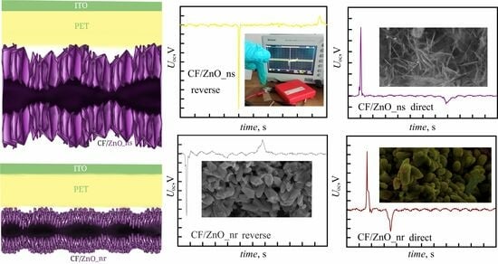
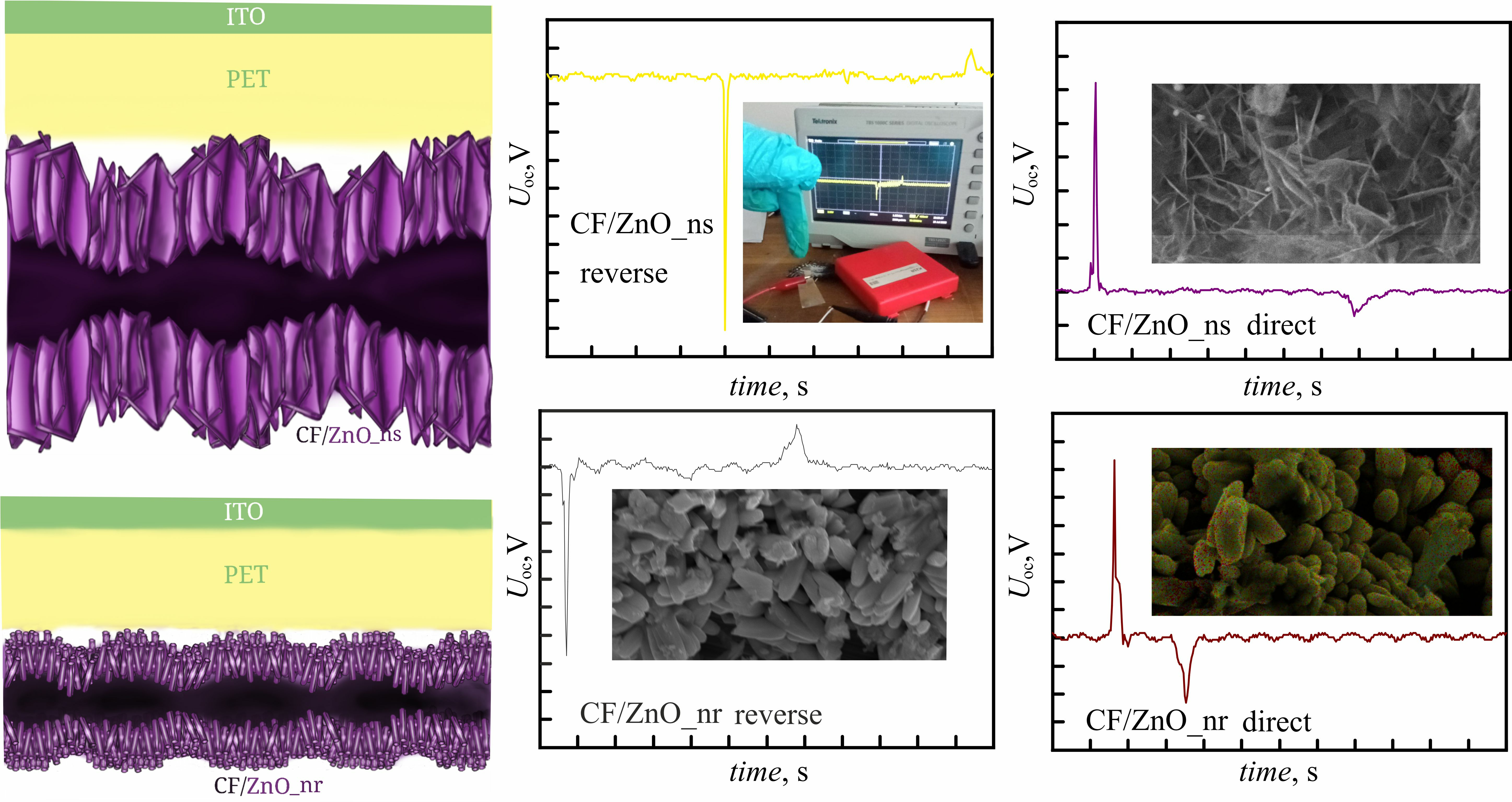
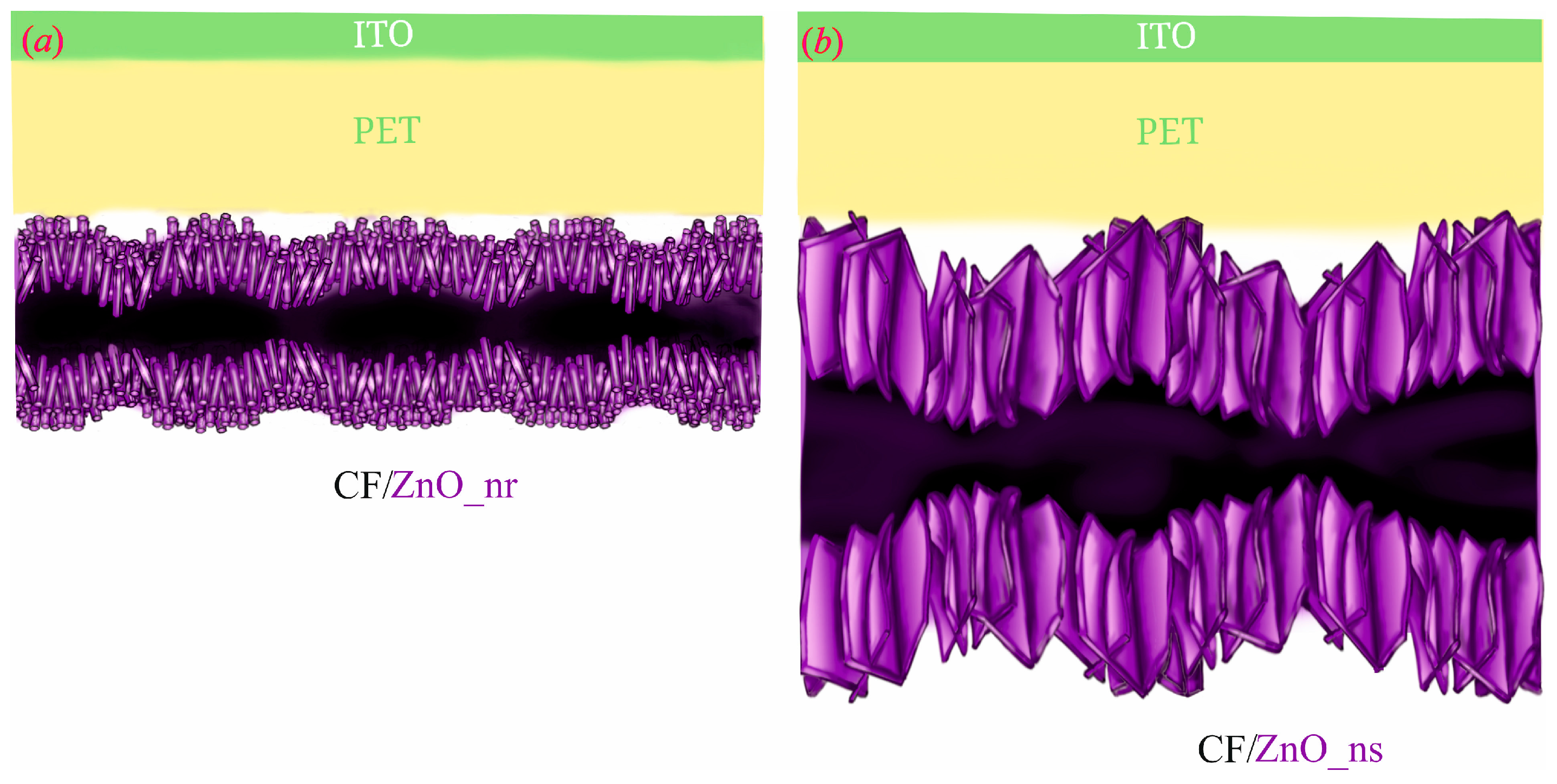
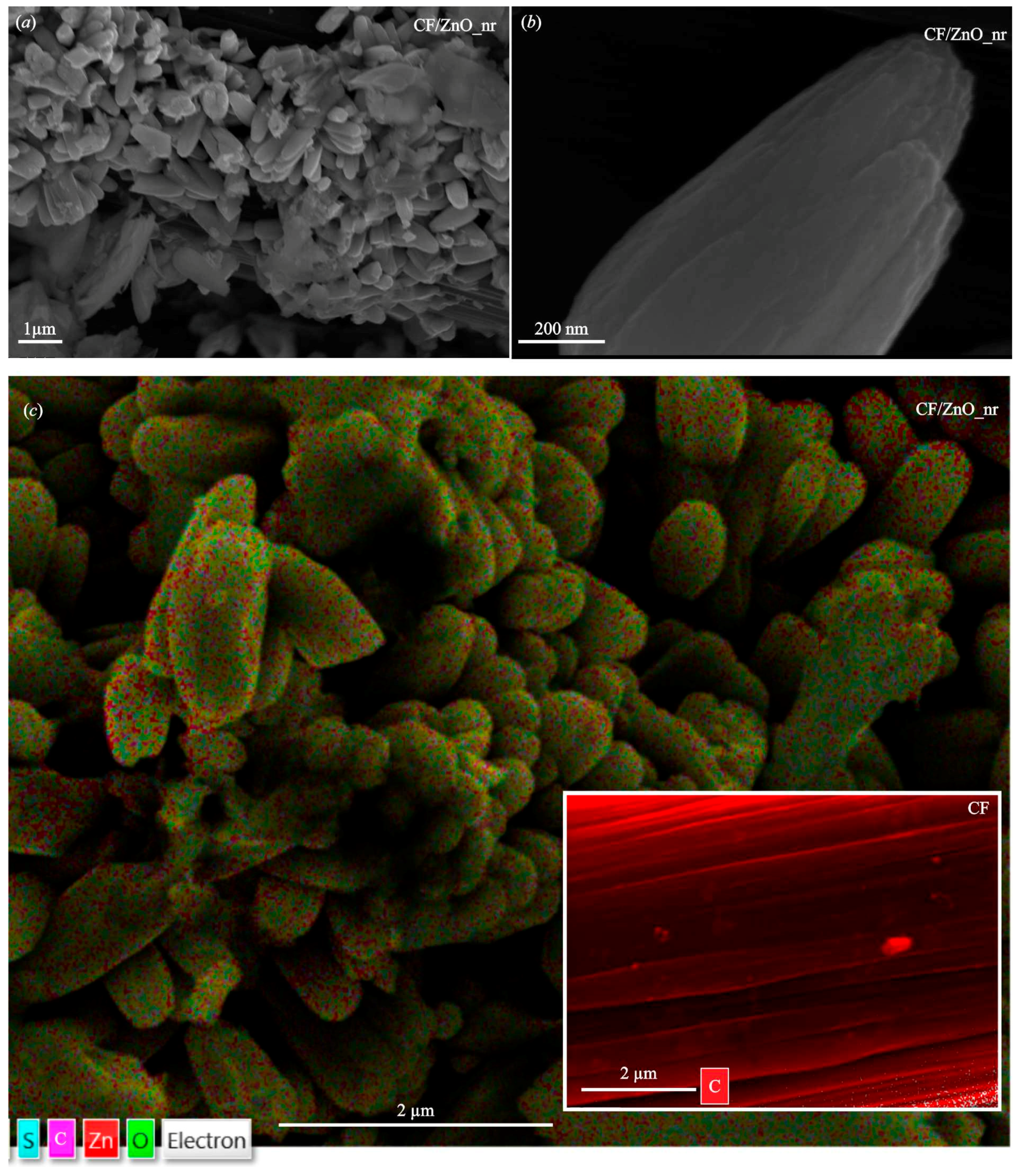
CF/ZnO_nr (~1 µm thick ZnO nanorods obtained by the SILAR method on the surface of CF fibers pre-coated with ZnO seed layers)916174
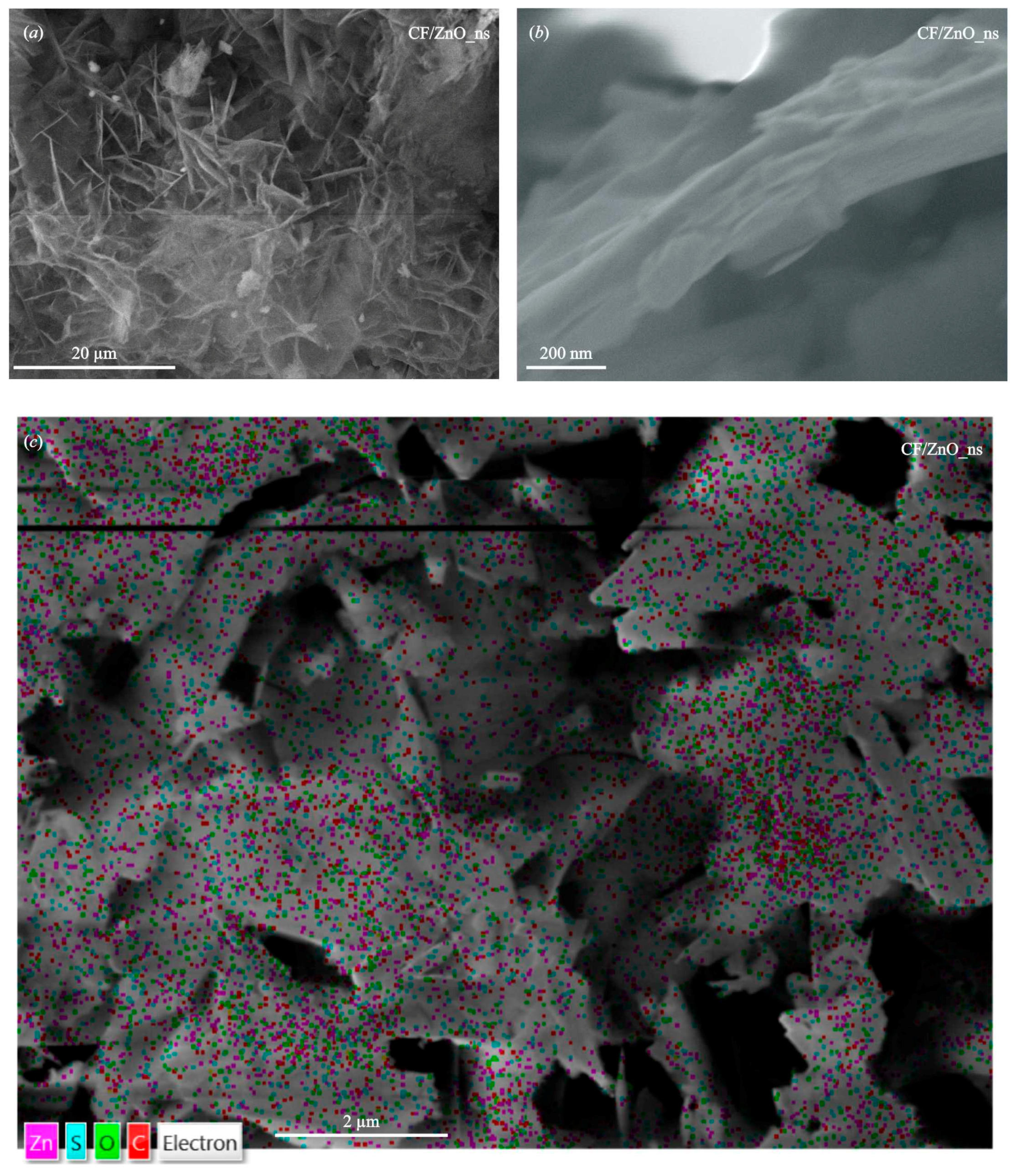
CF/ZnO_ns (~20 µm thick ZnO nanosheets fabricated by the SILAR method on bare CF)2746819
Table 2. Characteristics of single output signals obtained in external circuits with different load resistances for the developed TENGs, tapped with a force of ~5 N (pressure ~33 kPa).
TENGR, kΩJ, μA/cm2Q, nCU, mVP, nW/cm2
CF/ZnO_nr/PET/ITO2701.073.26432461
6200.871.93808699
48000.471.1533601568
CF/ZnO_ns/PET/ITO2701.473.58594871
6200.903.03837753
48000.501.2336001800
Disclaimer/Publisher’s Note: The statements, opinions and data contained in all publications are solely those of the individual author(s) and contributor(s) and not of MDPI and/or the editor(s). MDPI and/or the editor(s) disclaim responsibility for any injury to people or property resulting from any ideas, methods, instructions or products referred to in the content.

