1. Introduction
Ceramic matrix composites (CMCs) are composed of a combination of two materials: ceramics with metal or intermetallic material. In particular, the ceramic–metal system links materials of different chemical and physical properties, including chemical bonds. Despite these differences between ceramics and metals, which are not favorable in the fabrication process of ceramic–metal composites, they have been investigated for many years, and the basic knowledge about their structure, properties, and directions of development has been well documented [
1,
2,
3,
4]. The most important reason for these studies is to elaborate ceramic–metal composites with the desired properties, such as improved fracture toughness, high hardness, and good mechanical (bending strength) and tribological properties [
5,
6,
7,
8,
9]. Another interesting system is ceramic–intermetallic material. The composites of this system also possess improved fracture toughness, high hardness, and good properties at high temperatures [
10,
11,
12].
The majority of CMCs are composed of two kinds of ceramic powder and reinforcement. Depending on the ceramics, ceramic–matrix composites can be distinguished as oxide and nonoxide materials. The present work focused on oxide ceramics as a matrix of composites. Different shapes and sizes of ceramic and reinforcement particles were used to produce CMCs. As a result, various sizes, shapes, and phase distributions of the sintered materials were obtained. Moreover, in many ceramic–metal systems, new phases (spinels, oxides) as reaction products of substrates during processing can also appear [
5,
6,
7,
9]. This means that a complex micro-nano structure of composites can be formed. As a consequence, it enables the opportunity to create a large variety of micro-nano-structured combinations with a spectrum of known and as yet unknown properties. For this reason, in recent years, advanced CMCs, called hybrid composites, have been intensively elaborated and investigated.
Hybrid material is treated as a combination of two or more materials representing complex structures with phases of various morphologies and sizes for specific engineering purposes [
8]. Hybrid ceramic–matrix composites can combine more than two materials, for example, two ceramics with one metal or more than one with a complex structure and improved properties. In such multiphase composites with complex structures, it is possible to achieve the synergistic effect of the micro- and nanoparticles of the metallic phase, new compounds and ceramic phases on crack propagation, fracture toughness, and other properties, which is not possible in conventional materials.
As an example, the composite based on the Al
2O
3–Ni system with the addition of TiC can be mentioned. In this composite, good hardness and improved fracture toughness were obtained. The relative density of the composite was 98%. The Vickers hardness for this ternary composite was equal to 25.6 GPa and 30% larger than monolithic alumina prepared by the same method. The bending strength was improved up to 75% of the value obtained for alumina [
13]. These values are the result of the nanoparticles of Ni and TiC located in the microstructures. Moreover, TiC was added as a semiconductor phase to the composite microstructure with the aim of obtaining an electrical conductor composite [
13]. More examples of advanced composites are presented in another review paper [
9].
Such composites are advanced compared to conventional composites. The proposed division of composites into two conventional and advanced groups is conditional. Conventional composites can be interpreted as two-phase materials, the microstructures of which are shaped by one ceramic and one reinforcement. In particular, for composites fabricated by powder consolidation, the initial powders have a selected size and shape. In general, a uniform distribution of reinforcement with the same size and shape of particles in a ceramic matrix without a complex structure is expected. Such a distinction between conventional and advanced CMCs was made in the present paper.
In this paper, advanced ceramic matrix composites with metal particles and an intermetallic phase fabricated by powder consolidation without the liquid phase (molten metal) during processing were analyzed together with conventional composites. In particular, potential types of micro-nano hybrid structures were presented. Their microstructures, together with their geometrical schemas and selected examples of real ceramic oxide matrix composites, were described.
The presented geometrical schemas of CMC microstructures were based only on possible combinations of the initial sizes of ceramic and metal powders and their location. The assumption was made that the changes in the initial size of the powders as a result of some processing are not very significant; however, in some powder consolidation methods, it can be an important issue. Pores, which are typical of the various powder consolidation techniques, were also not included. It should be noted that when two or more substrates with various powder sizes are used to prepare a composite, the pore size and distribution are also more complex. In particular, when micro- and nanopowders are combined, two kinds of pores, micro- and nanopores, can be expected in the structure. The proposed geometrical schemas should be treated as a schematic representation of the types of the possible microstructures of CMCs.
A new concept of an advanced ceramic–intermetallic composite fabricated by the consolidation of pre-composite powder mixed with ceramic powder was also presented. CMC composites were fabricated based on our own experimental work, which was performed under the supervision of the author. Moreover, the properties and possible applications of CMCs were also analyzed.
2. Conventional CMCs
Ceramic matrix composites with incorporation metal or intermetallic phase are commonly known, and most of them are applied as engineering materials [
5,
6,
7,
8,
9,
10,
11,
12]. These composites, which can be called as conventional CMCs, are mostly two-phase materials with uniform distribution of reinforcement. However, graded composites are also fabricated. The knowledge of their microstructures, properties and fabrication is well documented in the literature. Phase composition and microstructures of classical CMCs depend on the ceramic-reinforcement system and method of fabrication.
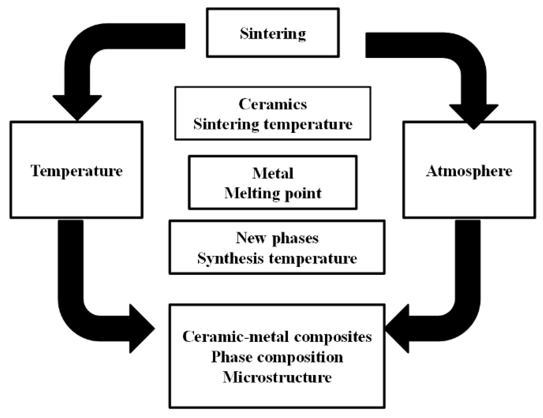
Powder consolidation techniques are one of the most popular methods of producing bulk composite materials [
6]. During sintering of powders, depending on the parameters of this process, the phase composition as well as microstructure of bulk material is formed [
5,
6,
7]. For a ceramic–metal system, the temperature and atmosphere of sintering are the key factors creating microstructures and phase composition (
Figure 1).
Microstructures of ceramic–metal or ceramic–intermetallic composites are mostly composed of ceramic grains and metal or intermetallic particles. It is well known that the final properties of composites depend on the size of both phases ceramic grains and reinforcement particles and the distribution of them. Starting from the micro-sized metal powder in composite, different sizes of metal particles and distribution in ceramic matrix can be achieved. The size of metal particles in composite can differ from the starting size of the metal powder. It depends on the method of powder consolidation and forming parameters. The agglomeration of metal particles occurs very often, and finally the agglomerates of metal particles are located in the ceramic matrix. Metal particles can be surrounded by ceramic grains as well as located at triple points or at ceramic grain boundaries (
Figure 2). Moreover, composite microstructures with mixed location of metal particles is also possible [
5,
6,
7]. The size of metal particles can be also reduced by mechanical process of powder mixing or when the temperature of sintering excessed the melting point of metal. In the second case, the size and distribution of metal particles will be controlled by sintering of ceramic powder particles. Sintering with participation of the liquid metal phase means that melted metal can penetrated between the ceramic powder particles and finally fulfil the pores in sintered bodies [
5,
6,
9]. Quite often, such ceramics as Al
2O
3 and ZrO
2, together with some metals, e.g., Ni, W Mo, Fe, Ti, and Cu, are combined [
5,
6,
7,
9,
11,
12].
Metal nanoparticles are also used to produce ceramic–metal composites. In the fabrication process, metal nanopowder is mixed with micro or nanopowder of ceramics. As a result, in the composite, metal nanoparticles are situated as separated particles surrounded by ceramic grains, or at the ceramic grains boundaries as well as in triple points. Mo, Ni, Ti and other metals are used and mixed with ceramics such as Al
2O
3 or ZrO
2. Nanocomposites represent hard materials but with improving fracture toughness [
6,
14,
15].
Composites combining ceramics and intermetallic phase have been also developed. Intermetallic materials are commonly used as a matrix because such composites have desired properties such as low density, high melting point, excellent wear and oxidation resistance [
10,
11,
12]. The incorporation of the intermetallic phase into the ceramic matrix allows us to improve properties such as yielding, toughness, flexural strength, hardness, wear resistance and also other properties. For example, composites of the Al
2O
3-TiAl system are investigated [
10,
12]. Al
2O
3 matrix composites incorporated with NiAl or Ni
3Al phases are also the subject of research [
11,
16].
Conventional ceramic matrix composites, well described in the literature, represent properties which are needed in many applications. For example, Al
2O
3 with Ni creates constructional composites with superior mechanical properties [
17]; in particular, the nanocomposite Al
2O
3-Ni, with its very low wear rate and high toughness, is considered for wear-resistant components and cutting tools [
18]. Al
2O
3-Ni composites are also applied because of their magnetic properties [
19].
Interesting properties and wide applications can be obtained for the Al
2O
3-Al system [
20,
21]. Owing to the high toughness, high thermal and electrical conductivity of Al, composites from this system can be applied as internal combustion engine piston crowns, connecting rods, turbine compressors and for bicycle components [
21]. Al
2O
3-Mo composites with laminated structure have very good self-lubricating, mechanical and tribological properties which give them the possibility to be applied as structural materials in high technology [
22]. For thermal barrier coatings and multifunctional devices, the mullite-refractory metals (Mo Nb) composites are used [
23]. ZrO
2 and Ni make composites for application as thermal insulation material [
24]. The combination of ZrO
2 with Ni gives a material with high strength and heat insulation, especially graded composite, i.e., porous ZrO
2-(ZrO
2 + Ni) can be used in aerospace engineering for bolted joints [
25]. ZrO
2 ceramics are also a good choice in medical applications, for example, in combination with stainless steel [
26]. ZrO
2-Ta is another ceramic–metal composite for restoration medicines [
27]. Metals, especially Ti or its alloys, are added to bioceramics such as hydroxyapatite [
28]. Additionally, Ti-Fe composite powder is added to hydroxyapatite to obtain bulk composite for the load-bearing biomedical application [
29].
Some applications desired graded materials which are called functionally graded materials (FGM) [
30,
31,
32]. Such structures have gradually distributed reinforcement particles which means that as a result of technological process a continuous change in properties is obtained [
31,
32,
33]. The final graded structure depend on the method of fabrication and initial components especially their chemical composition size, shape and contribution are important [
33]. FGM can be applied as constructional and functional materials. For example, as thermal barriers, turbine blades, tools for plastic forming in automotive and aerospace industries as well as biomaterials or optoelectronic materials [
30,
31,
32,
33,
34].
Various methods can be used to create FGM structures. It can be listed infiltration method, laser sintering, laminating, powder injection molding, electrolytic deposition, plasma sintering, centrifugal slip casting, slip casting with using the magnetic field and others [
34,
35,
36,
37,
38,
39,
40,
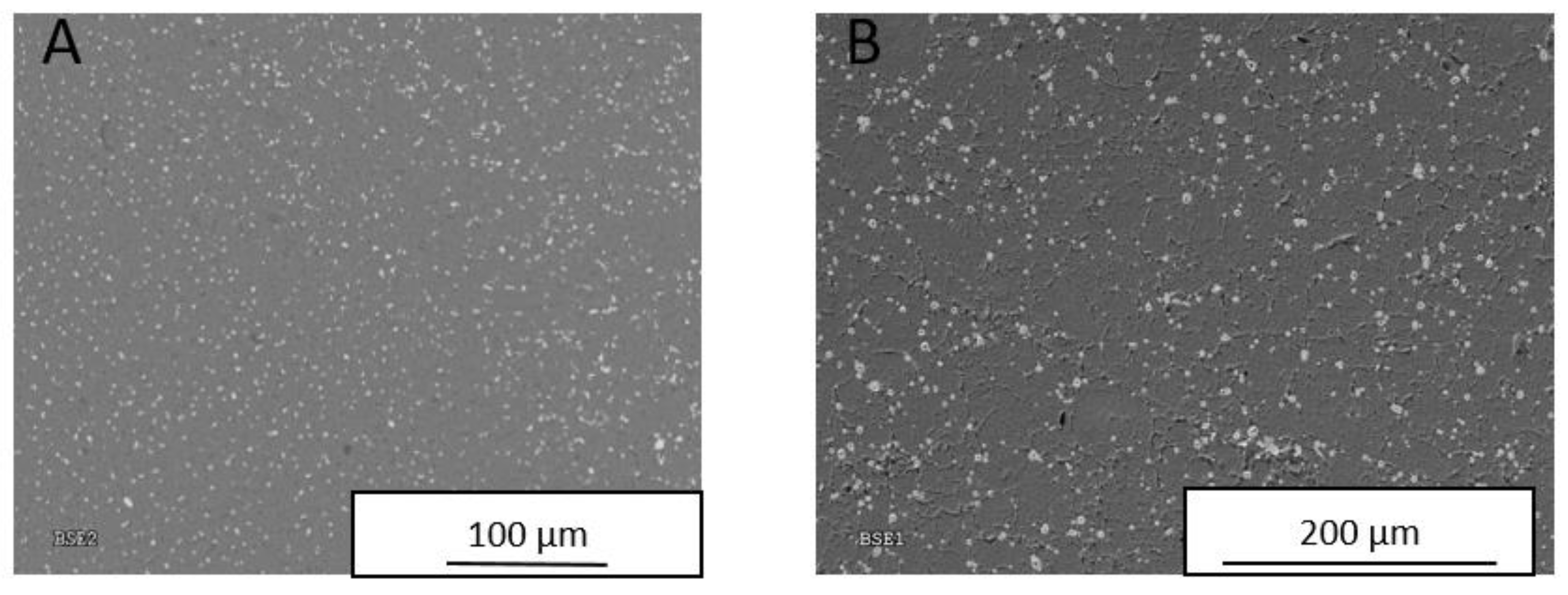
41]. In our own research for fabrication of graded ceramic matrix composites, the following methods were used: slip casting (gravity gradient), slip casting with magnetic field operation, centrifugal slip casting as well as additionally with magnetic field. As a result, non-random distribution of metal particles was obtained. Moreover, the metal particles concentrated close to each other and made chain patterns, as presented in
Figure 3. The presented microstructure of Al
2O
3-Ni composite was obtained by the slip casting method with the use of magnets during processing. At the top of the sample, the Ni particles were uniformly distributed into the ceramic matrix (
Figure 3A). At the bottom of the sample, where the magnet was placed, the concentration of Ni particles was higher and a chain pattern was formed (
Figure 3B). Our own research considered such systems as Al
2O
3-Ni, Al
2O
3-Mo, Al
2O
3-Cu, Al
2O
3-W and also ZrO
2-Ni [
42,
43,
44,
45]. Graded composites can be also multiphase materials with complex structures; however, their processing is more complicated than classical two-phase composites with graded distribution of them.
3. Advanced CMCs
Although the conventional ceramic matrices are commonly fabricated and most of them are applied, still there is a need to elaborate new advanced composites with a ceramic matrix. Advanced CMCs are based on conventional composites, the known rules of shaping their structures and properties. However, the development of advanced CMCs demands new concepts of design and fabrication of desired microstructures and properties. The new concepts of advanced composites include multiphase and complex structures called hybrid [
8]. In hybrid CMCs, various variants of combining ceramics with metals and also intermetallic phases are possible, as opposed to conventional CMCs, in which there is only one ceramic and one reinforcement composed of microstructures.
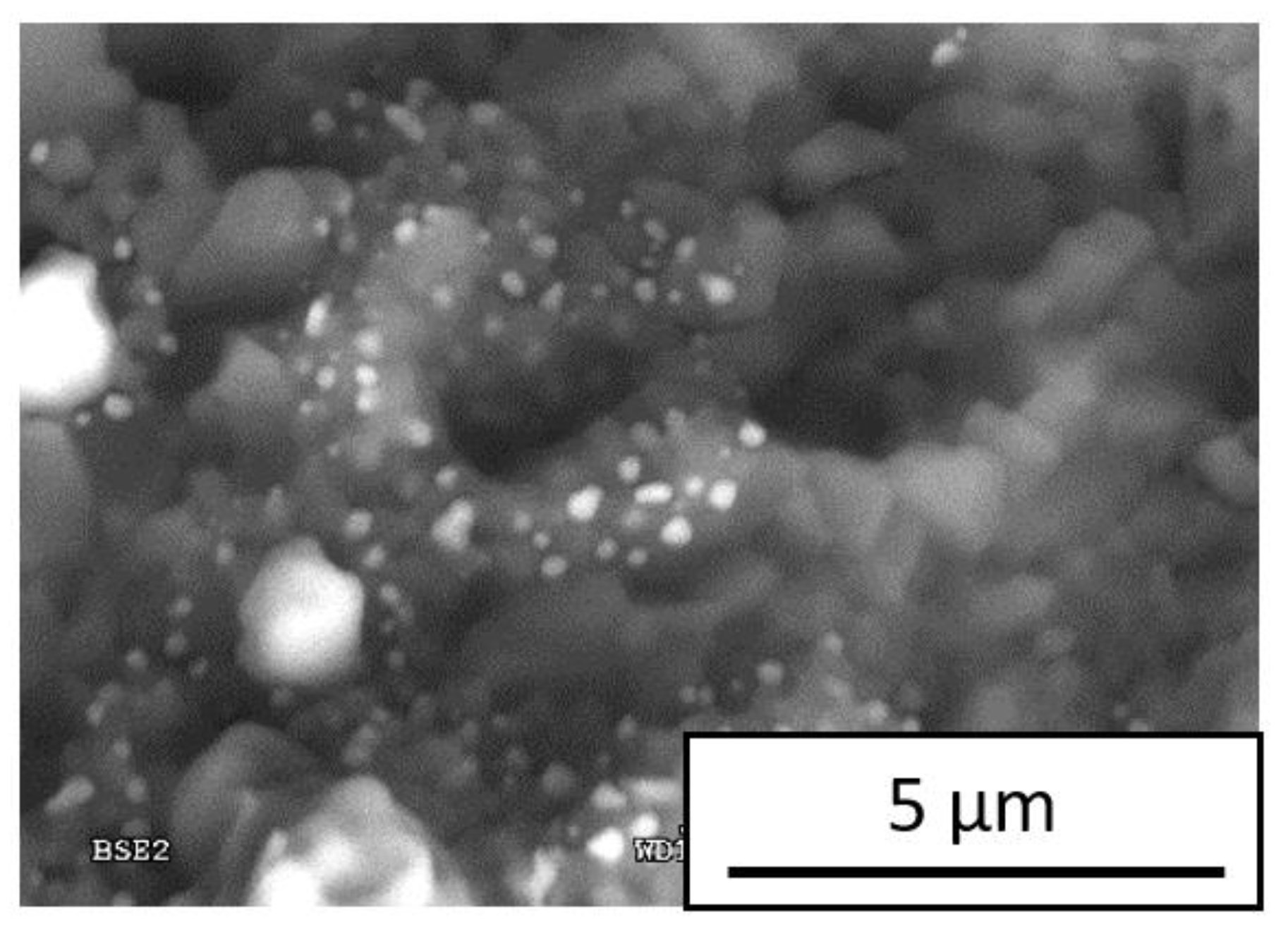
One example of such composite links a ceramic matrix with one metal but is located in a matrix in the form of both micro and nanoparticles. To prepare such composites, two metal powders can be used, one with micro and the second with nanoparticles. These metal powders can be combined with micro or nanoparticles of ceramic powder particles. Such combinations of ceramic and metal powders and their consolidation provide us with various options of microstructures. The geometrical schemas of predicted microstructures of such CMCs are collected in
Table 1. An example of a real microstructure of composites, type IA according to
Table 1, is presented in
Figure 4. In this selected example, Ni powders with different sizes of micro- and nanopowders were used and combined with ceramic micropowder. Bigger Ni particles are surrounded by ceramic grains, and smaller Ni particles are situated at triple points and at the ceramic grain boundaries as well as inside the ceramic grains (
Figure 4). For bigger Ni particles, deflection of the crack is expected. Crack deflection by larger metal particles as well as Ni were reported in the literature [
5,
6]. Small Ni particles effectively redirect or stop the cracks [
6].
Ternary system composites, where two ceramics are combined with metal, or one ceramic with two metals, or other combinations also with intermetallic compounds, also belong to the new composites with complex structures. There are papers describing the composites of ternary systems such as ZrO
2-Ti-Ni [
46] or Ni-Ti-ZrO
2 [
47]. Results suggested that the addition of one more substrate provides an increase in mechanical properties with respect to the two substrates in composites obtained by the same method. For example, composites of the Ni-Ti-ZrO
2 system are considered as anodes for high temperature fuel cells, because both their mechanical properties and the anode performance are better than for those prepared in the same way but containing two components, Ni-ZrO
2 and Ti-ZrO
2 [
47]. There are also papers which report the results of investigations of composites with Al
2O
3 matrix with the addition of ZrO
2 and Ti(C,N) [
48], Al
2O
3-ZrO
2-Nb [
49] as well as three components such as Al
2O
3-ZrO
2-CeO
2 with the addition of Ni [
50]. Another example is a composite which links ZrO
2 with Al
2O
3 and (Ti,W)C [
51]. These composites were fabricated by hot pressing or die pressing and sintering.
Composites consisting of three substrates such as one ceramic matrix and two metals fabricated from initial powders, with their various initial sizes, can form complex microstructures in which metal reinforcements can be located as separated particles, at the grain boundaries of the ceramic matrix as well as inside the ceramic matrix grains. According to the size of ceramic and metal powders, the schemas of microstructures and location of reinforcements are presented in
Table 2 (C1 + M1 + M2). Moreover, the same type of microstructures represented by schemas in
Table 2 will be created through a combination of two ceramics, one as a matrix and a second as reinforcement, and metal as the next reinforcement phase, which is presented in
Table 2 (C1 + C2 + M2).
Presented in
Table 2 are geometrical schemas of microstructures of CMCs based on possible combinations of one ceramic powder as a matrix combined with two various metals, or two ceramics and one metal with different sizes of initial powders and various location of phases at composites. Such combinations lead to models which are the same geometrically. The fact that schemas of microstructures are the same geometrically does not mean that the properties represented by these microstructures are the same. However, types of microstructures and their schemas can be useful in the process of composite tailoring and prediction of their properties.
The author’s own experiments, under the supervision of Konopka, based on composites with complex microstructures concentrating on the Al
2O
3 metal and ZrO
2 metal composites in which Ni, Ti and Ti +Ni were used [
52,
53,
54,
55]. The microstructure of ZrO
2-Ti-Ni composite is presented in
Figure 5A. Three phases are visible: matrix ZrO
2, Ti particles and Ni particles. In the presented microstructure, the Ti and Ni phases are located as separated by ceramic matrix or located as neighbors. The nanometric initial powder of ZrO
2 and micrometric Ti and Ni powders were used in fabrication of composites. The microstructures of ZrO
2-Ti-Ni composite can be represented by the type IIE (
Table 2), where one ceramic matrix and two metals with various sizes of powders were combined.
The second composite investigated in our own research system was Al
2O
3-TiC-Ti. This system represents a combination of substrates as follows: two ceramics, one as matrix of composite and the second one as reinforcement, and metal as another reinforcement. In this combination, the various options of size of powder particles can also be considered. In the presented composite, Al
2O
3 is a matrix and Ti and TiC particles are located in the ceramic matrix (
Figure 5B). The metal particles as well as their agglomerates are distributed in the ceramic matrix. However, chains of fine Ti particles were also found at the TiC/Al
2O
3 interface (
Figure 5B). The microstructure of this composite can be classified as IIB in
Table 2.
In the group of advanced CMCs are multiphase composites with new phases forming during the processing. For oxide ceramics combine with some metals spinel phase or metal oxides can be synthetized during process of sintering. They are mostly located at the ceramic/metal interfaces. In particular, the spinel phase can surround the metal particles [
56,
57]. Because of a weaker spinel/metal interface than spinel/ceramics interface, after pulling out metal particles, voids very often exist in the microstructures (
Figure 6A,B). Such a feature of spinel morphology, i.e., an oval shape with a hole inside, which can be called “doughnut” shape, was analyzed in own works. Moreover, experimental work revealed a relationship between the size of metal particles and the size of the spinel. It was found that the contribution of spinel volume is even eight times higher than the volume of the metal particles [
58,
59]. In such a spinel volume in microstructures, its influence on properties can be significant.
The spinel is active in crack propagation. Cracks are mostly deflected by the spinel phase [
6,
56,
57,
60]. In cases where all metal is transferred to the spinel phase, the composites consist of two phases, i.e., ceramics and spinel. The microstructure of this composite can be considered as a typical classical two-phase composite. On the contrary, when both spinel and metal are in the composite microstructure, various spinel locations and its thickness can be noticed. As presented in
Figure 6C, in composite Al
2O
3-Ni, the spinel phase NiAl
2O
4 consists of fine grains surrounding the metal particles and does not have a regular shape and thickness. Such a microstructure can be classified as a complex ternary microstructure of composite where the ceramic is a matrix, and the metal and spinel phase are reinforcements. Such a complex microstructure depends on the shape and distribution of the spinel, and there are no geometrical schemas of it in
Table 2.
In the same group as the above-mentioned group of CMCs are composites in which various oxides of metals are formed. Their location can create the complex microstructures. Very fine oxide particles can be located at grain boundaries of the ceramic matrix as well as at ceramic/metal interfaces and also inside the grains and interlocked by ceramic grains (
Figure 6D). These fine particles of oxides can very effectively stop and redirect the crack propagation. Moreover, because of their high hardness, the effect of hardening can be noticed. Our own investigations of composites ZrO
2-Ni and ZrO
2-Ti, in which very fine oxides particles were identified, confirm this effect [
53,
54,
57]. In particular, in the ZrO
2-Ti system, very fine (100 nm) phases, Zr-Ti-O and precipitation of titanium oxides ZrTiO
2 were located in the ceramic matrix [
49]. This composite geometrical schema of a microstructure can be considered as type IID from
Table 2 where nano-sized ceramic matrix is combined with micro-sized Ti particles and nanoparticles of Zr-Ti-O phase and ZrTiO
2.
Another example of CMCs with complex microstructures are composites which are fabricated by consolidation of composite powders. For example, reactive milling of initial substrates NiO and Al leads to the production of composite powder NiAl-Al
2O
3, and then after consolidation of it, the NiAl-Al
2O
3 bulk composites are obtained [
61]. Complex microstructures of such composites depend on the size, shape and distribution of the new products.
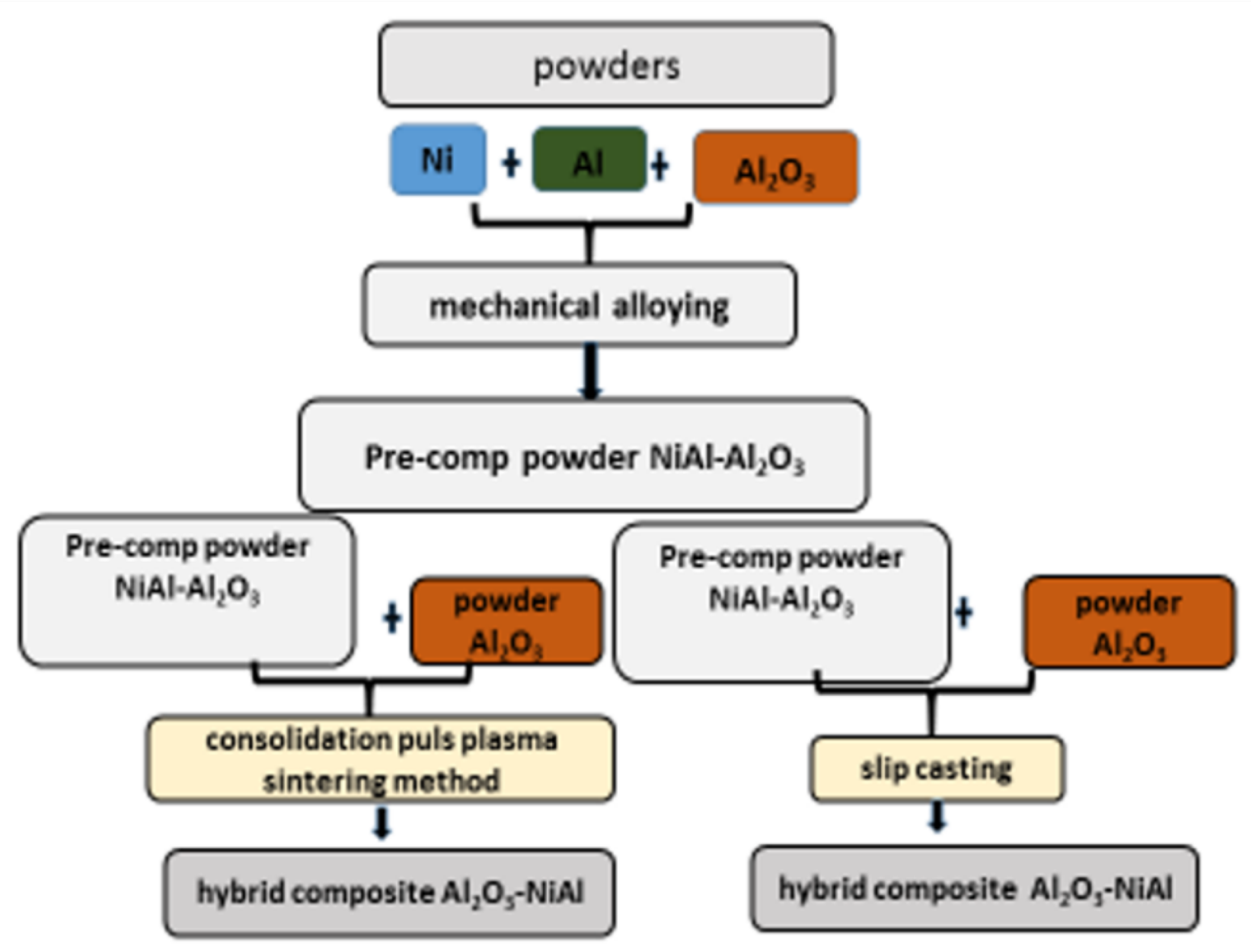
Our own research also concentrated on such composites. The following concept of them has been developed. Substrates as two metals in the form of powder are selected in such a way that during proper processing they will create new a compound, intermetallic material. From these two selected metals and the added ceramic powders, a composite powder is prepared (called pre-composite powder). This pre-composite powder consists of intermetallic material and ceramics. In the next step of the process, pre-composite powder is mixed with ceramic powder and consolidated to obtain the final bulk ceramic matrix composite. As an advantage of this concept, uniform distribution of constituencies in pre-composite powder and, moreover, being kept in bulk composites formed by consolidation of pre-composite and ceramic powders should be underlined. Finally, the microstructures of composites have ceramic matrix and reinforcement composed of two phases, intermetallic and ceramics. Such composites belong to novel bulk ceramic matrix composites with intermetallic phase, complex structures and improved mechanical properties. However, in the literature, it is mostly results of intermetallic–ceramic composites that are presented, or ceramic–intermetallic composites fabricated from initial ceramic and intermetallic powders.
The innovative method of composites fabrication using the pre-composite powder consisting of the intermetallic compound comes from the fact that intermetallic material is also regarded as efficient reinforcement of composites, for example, composites of Al
2O
3-TiAl [
10]. The intermetallic particles can retard the crack propagation and deflect the crack path, and therefore, the stress is released and the fracture energy is increased. Moreover, the intermetallic phase could also contribute to the hardness of the composite due to its high hardness [
11]. NiAl is a potential material for use in high temperature applications. The melting point of NiAl is as high as 1640 °C; furthermore, the oxidation and corrosion resistance of NiAl are superior among intermetallic materials. The elastic modulus of NiAl is lower than that of Al
2O
3 (188 GPa vs. 380 GPa); however, the toughness of NiAl is higher than that of Al
2O
3 [
16]. Because of that, various materials are added to NiAl to make a composite with improvement in fracture toughness. Among of them are NiAl-Al
2O
3 composite [
61]. Moreover, the chemical inertness of alumina may not be degraded significantly as NiAl is added. Both materials NiAl and Al
2O
3 have low density. These features make NiAl an excellent partner to work together with Al
2O
3.
Composites with a ceramic matrix (Al
2O
3) and intermetallic phase (NiAl) fabricated from pre-composite powder have been intensively investigated by the group of K. Konopka within the frame of a project within the Excellence Initiative: Research University (IDUB) program funded by Warsaw University of Technology. In elaborated composites, complex structures and positive results of intermetallic material distributed in a ceramic matrix on mechanical properties are expected. In particular, because of a lower value of NiAl elastic modulus than for Al
2O
3 matrix, the bridging effect can appear as well as deflection of the crack path by NiAl. Our own preliminary results are presented in [
62]. A schematic diagram of the technological steps in the fabrication of a new type of hybrid composite is presented in
Figure 7.
Geometrical schemas of composites representing the proposed concept include some possible variants of selection of metals, ceramics as well as size of their powders. These variants of pre-composite powders are presented in
Table 3. The schemas of predicted microstructures of composites obtained by consolidation of pre-composite powder (represented in
Table 3) with ceramic powder are proposed in
Table 4.
The proposed concept could create the bulk ceramic matrix composites with intermetallic phase. It is expected that in areas composed of pre-composite powder, the intermetallic phase will make continuous interlocking skeletons and effectively take part in crack propagation. The crack propagation should be stopped and should not transfer to the neighboring grains. Such behavior should be observed in all types of composites composed of pre-composite powders (
Table 4 type IIIA, IIIB, IIIC, IIID). Additionally, the nanoparticles of ceramics in pre-compo 1 powder (
Table 3) and finally in composites types IIIA and III B (
Table 4) should also take part in the process of crack path propagation, especially by stopping or redirecting the cracks. Ceramic–intermetallic composites with such microstructures seem to be very promising for possible application as high temperature structural materials in the energy industry, aerospace or as a wear-resistant material.
4. Effect of CMCs Structure on Properties
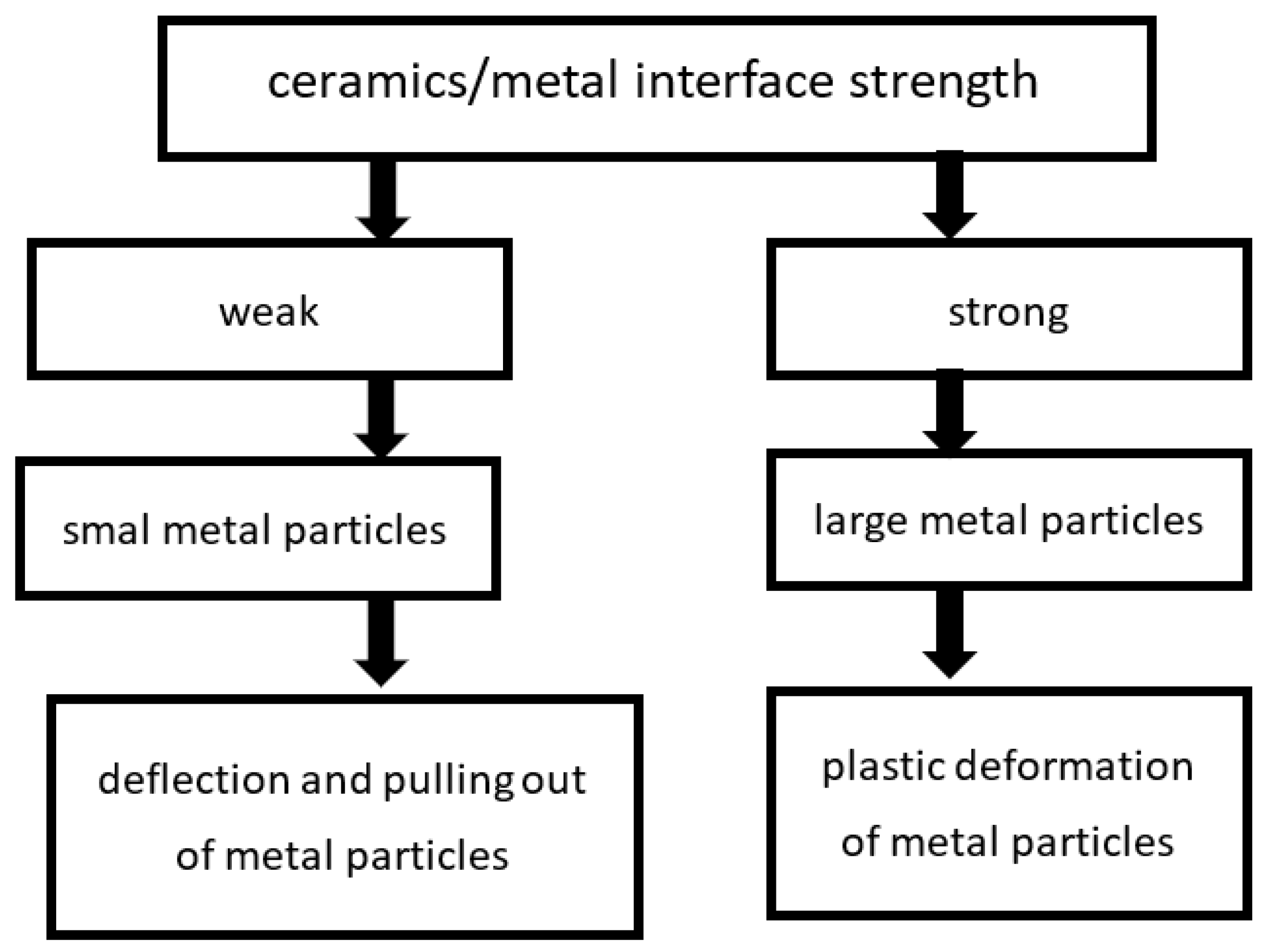
The most important aim of introducing reinforcement into a ceramic matrix is improving the fracture toughness of new materials compare to the ceramics. The mechanisms of improving the fracture toughness depend on the ceramic–metal system and composite microstructures. The bridging and deflection of cracks by the metal particles as the effective mechanisms of crack energy dissipation and increasing fracture toughness are well known [
5,
6,
7]. The strength of the interface between ceramics and metal is responsible for the operation of these particular mechanisms of fracture toughness improvement [
5,
6,
7] (
Figure 8).
For weak bonding between ceramics and metal particles crack propagation along the interface, deflection of the crack path is dominated [
5,
6,
7]. Moreover, the metal particles are being pulled out from the ceramic matrix. Strong interface bonding between ceramics and metal particles results in a bridging mechanism. It is the most effective mechanism because it involves the plastic deformation of metal particles [
5,
7]. There are also other mechanisms which can be active in ceramics as well as in ceramic matrix composites, i.e., transformation toughening, micro-crack toughening, bridging by matrix grains or crack field voids formation [
63]. In composites with ZrO
2 matrix, the martensitic transformation of tetragonal t-ZrO
2 into monoclinic m-ZrO
2 is possible [
6,
64]. The metal particles such as Ti can influence the martensitic transformation, and in this way, they can exert an influence on strength and fracture toughness of composite material [
65,
66].
Nanoparticles of metal and their influence on the properties of ceramic matrix composites are also the subject of research [
5,
6,
9]. In the fabrication process, the nanopowders of metal are mixed with micro- or nano-ceramic powder. As a result, composite nanoparticles of metal are situated as separated particles surrounded by ceramic grains, or at the ceramic grains boundaries as well as in triple points. Nanocomposites represent hard materials but with improving fracture toughness, which is an effect of nanoparticles of metal, which very effectively stopped the crack propagation [
52]. For nanoparticles situated along the grain boundaries, their tendency to change the intergranular fracture to transgranular and toughen the composites were noticed [
15].
All of the mechanisms for crack energy dissipation by reinforcement phase in CMCs are active in hybrid composites. The multiscale effect of micro- and nanoparticles of reinforcement on the microstructure and properties of advanced hybrid composites has not been thoroughly studied. However, the synergistic effect of different mechanisms of crack energy dissipation is announced [
9,
50]. Niihara et al. [
67] have shown that the hybridization of microcomposites and nanocomposites leads to improvements in strength and toughness. For example, in multiphase composites, Al
2O
3-ZrO
2-CeO
2 with the addition of Ni, or TiO
2 led to an increase in the fracture toughness being obtained [
50]. In the work of Kim et al. [
68], a fabricated composite consisting of 40 vol.% of ZrO
2, 30 vol. % spinel and 30 vol.%Al
2O
3 exhibited a higher strength compared with the strengths of the constituent phases. The bend strength of composite sintered at 1550 °C was equal to 658 MPa [
68].
The increase in fracture toughness while keeping the high hardness is also observed in own investigation of composites with spinel phase [
57,
59].
In composites with an intermetallic phase, the intermetallic particles can retard the crack propagation and deflect the crack path; therefore, the stress is released and the fracture energy is increased. Moreover, the intermetallic phase could also contribute to the hardness of composite, due to the high hardness of the former [
12].
However, the state of knowledge concerning hybrid composites of ternary systems and multiphase systems is inconsiderable. It is because of this fact that in hybrid composites, as a consequence of their complex structure obtained by the intermixing of different phases with various size, shape and distribution, describing the relationships between the structures and properties is difficult. In particular, it should be expected that cracks reaching the areas of complex phases, due to simultaneous activation of various mechanisms as redirection, deflection, and pulling out, will be effectively stopped and will not coming out, as presented in
Figure 9A. Such an effect is predicted in composites composed of compaction of pre-composite powder represented by all geometry models (
Table 4).
In hybrid composites, the bigger particles, separately located in the ceramic matrix, will also contribute to the interaction with the propagating crack. The crack propagation through the metal particle or new phases and crack bridging are expected, as presented in
Figure 9B,C. For example, for composite ZrO
2 with 10 vol.% of Ti, a positive effect of formed Ti-Zr-O phases for mechanical properties of composite was noticed. Hardness was equal to 11.2 GPa and bending stress 170 MPa. On the contrary, for the reference sample ZrO
2, hardness was equal to 12.5 GPa and bending stress 220 MPa. The fracture toughness, measured by Vickers indentation method, for composite was almost two times larger than for pure ceramics [
55,
69].
In composites which were prepared from pre-composite powder according to the concept presented in paper, the high hardness was achieved. First, pre-composite powder was prepared by mechanical alloying of powder mixture Ni-50 at.% Al with contribution of 10 and 20 wt.% of nanometric Al
2O
3 powder. Then, Puls Plasma Sintering was applied as the consolidation method, and as a result, composites with the nanocrystalline NiAl matrix and fine inclusions of Al
2O
3 were obtained. These composites had a hardness equal to 7.2 GPa for 10 wt.% Al
2O
3 and 8.4 GPa for 20 wt.% Al
2O
3 [
62].
Additionally, using pre-composite powder as an initial powder mixed with Al
2O
3 powder, and by slip casting produced bulk materials which gave the composites (Al
2O
3—(NiAl + Al
2O
3)) with complex structures high density and favorable mechanical properties. In samples using initial pre-compo-powder (2.5 vol.% of (NiAl + Al
2O
3)), the fracture toughness was equal to 6.2 MPa·m
0.5. For samples using initial pre-compo-powder (5 vol.% of (NiAl + Al
2O
3)), the fracture toughness was equal to 6.19 MPa·m
0.5. In addition, the fracture toughness value for pure Al
2O
3 ceramics was 5.18 MPa·m
0.5 [
70].


