Article

A Better Understanding of the SBA-15 Pores Filling through Textural Changes in CMK-3 Carbon Synthesis and Its CO2:CH4 Adsorption Selectivity

by
Karla Quiroz-Estrada
1,*,
Marcos Esparza-Schulz
1,* and
Carlos Felipe
2,*
1
Departamento de Química, Fisicoquímica de Superficies, Universidad Autónoma Metropolitana-Iztapalapa (UAM-I), Mexico City 09340, Mexico
2
Departamento de Biociencias e Ingeniería, CIIEMAD, Instituto Politécnico Nacional, Mexico City 07340, Mexico
*
Authors to whom correspondence should be addressed.
J. Compos. Sci. 2022, 6(11), 344; https://doi.org/10.3390/jcs6110344
Submission received: 11 October 2022 / Revised: 25 October 2022 / Accepted: 1 November 2022 / Published: 7 November 2022
(This article belongs to the Section Carbon Composites)

Abstract

:
This text reports the morphological and textural behavior of the synthesis stages of a CMK-3 carbon type using a silicon matrix of the SBA-15 type calcined at 823 K as a template. During the synthesis, three intermediate materials were obtained because of (i) the addition of sucrose to the SBA-15 template (CCMK3-1st), (ii) the addition of sucrose to the CCMK3-1st material (CCMK3-2nd), and (iii) the carbonization by pyrolysis of the by-product CCMK3-2nd (CCMK3-F). The texture of the above materials was found by analyzing the N2 adsorption isotherms, applying the classical adsorption theories to obtain the BET-specific surface and the meso- and micropore distributions by the BJH and Dubinin–Astakhov (DA) methods, respectively, in addition to the non-localized density functional theory (NLDFT). Similarly, with high resolution, the samples were analyzed morphologically by scanning electron microscopy (SEM) and transmission electron microscopy (TEM). Finally, the adsorption isotherms of CO2 and CH4 of the CMK-3 sample were obtained at six different temperatures in the interval of 243 to 303 K to evaluate the behavior of the isosteric enthalpy of adsorption (qst) and its CO2:CH4 ideal selectivity. The final CMK-3 carbon presented two families of micro- and mesopores of 1.5 and 3.2 nm, nanopipe diameters of 3.5 nm, and a specific surface area of 1350 m2/g. It also presented values of 6.0 and 2.4 mmol/g adsorbed CO2 and CH4 at 243 K, respectively, and strong intermolecular interactions, with qst values higher than 22 kJ/mol reflected in high selectivity values for an ideal mixture of CO2:CH4 (30:70%).

1. Introduction

The synthesis of materials by the hard-templating route, also called “nanocasting”, is used to obtain mesoporous structures. This method ensures that the mesoporous channels of the templates are filled and have the advantage of being resistant to high temperatures [1].
Template methods are suitable for controlling structure development and carbon nanoporosity [2]. Nanoporous carbons with a homogeneous structure and uniform pore size can be prepared using soft or hard templates, where the main disadvantage of the first one is the fact that it is not possible to control the size and shape of the products, contrary to the hard template, which may use ordered mesoporous silicates and, moreover, are relatively abundant. In particular, SBA-15 is an efficient hard template due to its highly ordered hexagonal mesoporous structure [3]. Among the materials obtained by this technique are ordered mesoporous carbons such as CMK-3, with a high specific surface area; pore volume; and excellent chemical, mechanical, and thermal stability. These characteristics are suitable for diverse applications such as energy storage [4,5], catalysis [6,7], water purification [8], and detection and adsorption of different gases [2,9,10].
In 2000, Ryoo et al. [11] synthesized the CMK-3 carbon structure for the first time, using SBA-15 silica as a template, sucrose as a carbon source, and H2SO4 as a catalyst. Sucrose hydrolysis is accompanied by polymerization reactions, which result in the formation of large molecules that are difficult to detect by classic techniques such as gas chromatography-mass spectrometry (GC-MS), and their structure cannot be determined. However, these macromolecules are defined as soluble oligomers. Further aggregation of the soluble oligomers forms insoluble polymers (carbon materials) [12]. CMK-3 carbon is the inverse replica of the SBA-15 silica structure, both with P6mm symmetry [13]. This type of carbon is formed by hexagonal arrays of carbon nanorods linked by interconnecting pores [14]. The CMK-3 synthesis method consists of four steps: (1) synthesis of the SBA-15 template, (2) infiltration of the template with a carbon source and its polymerization, (3) carbonization of the Si/C composite, and (4) removal of the template with HF solution [15]. Each step of the CMK-3 synthesis represents changes in the porosity and structure of the matrix materials, composites, and final products.
In most carbon materials, the affinity for gas adsorption is related to the adsorbent’s porosity and pore size distribution. CMK-3 is a promising ordered mesoporous carbon (OMC) for CO2 storage due to its large pore volumes [16] and tunable pore diameters given by the SBA-15 silica template [17]. When the pore diameter is very narrow, CO2 is more easily retained due to the higher quadrupole moment than CH4 and N2; this behavior makes them viable materials for the bulk separation of mixtures such as CO2:CH4 [18]. Capture and sequestration currently constitute the most prominent options to reduce atmospheric CO2 accumulation and its adverse effects, often offering an attractive combination of performance and cost [19]. Because CH4 often coexists with CO2 in gaseous mixtures, such as natural gas, biogas, and landfill gas, the selective removal of CO2 is a necessary process to improve the energy content of those mixtures [20].
Therefore, in the present work, we tried to contribute to the mechanism understanding by which the CMK-3 type mesoporous carbon structure is formed. For the above, the N2 adsorption technique explored the porous cavity and textural behavior of the by-products formed in each stage of the CMK-3 synthesis. Finally, and as an application, the capacity, selectivity, and adsorption enthalpies of CO2 and CH4 possessed by the CMK-3 material were explored in a wide range of temperatures (243 K–303 K).

2. Materials and Methods

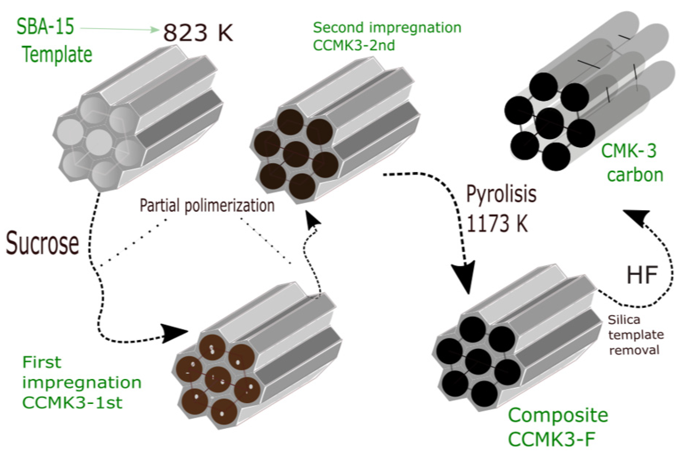
2.1. SBA-15 and CMK-3 Carbon Synthesis

The synthesis of the SBA-15 material was carried out following the modified methodology by Ojeda-López et al. [21] at a calcination temperature of 823 K. The procedure used 4.0 g of copolymer P-123 in solution under constant stirring with 120.0 g of deionized water and 24 g of 36.5–38% HCl. Once dissolved, 9.6 mL of TEOS was added drop by drop. The resulting mixture was stirred at 313 K for 20 h, and the solution was aged at 353 K for 48 h under static conditions. The sample was filtered with distilled water and dried at 373 K for 24 h. Finally, the organic template was removed by calcination at 823 K in a tube furnace for 4 h. A calcined SBA-15 sample was used as a template in the CMK-3 carbon synthesis [11], where 1 g SBA15 was mixed with 1.25 g sucrose and 0.14 g H2SO4 in 5 g H2O for the first impregnation step (CCMK3-1st). The sample was mixed for 3 h at constant stirring, and the resulting sample was sonicated for 30 min in an ultrasonic bath. First, the mixture was dried for six hours at 373 K for water evaporation. Then, the temperature was increased to 433 K for partial polymerization for the same time in a tubular oven under airflow using a heating ramp of 1 K/min. The resulting composite was mixed with 0.8 g of sucrose, 0.09 g of H2SO4, and 5 g of water for a second impregnation (CCMK3-2nd), following the previous stirring, sonication times and heated ramps at 373 and 433 K to complete the polymerization. In contrast, the carbonization was completed by pyrolysis at 1173 K with an N2 flow of 100 mL/min. The final carbon-silica composite (CCMK3-F) was washed with a 5 wt% HF solution at room temperature to remove the silica template. The final carbon product (CMK-3) was filtered, washed with ethanol–water solution, and dried at 393 K (Figure 1).

2.2. Morphological, Textural, and Structural Characterizations

The SBA-15 and CMK-3 samples were morphologically characterized by high-resolution scanning electron microscopy (HRSEM) in a JEOL unit, model JSM-7800F (JEOL USA, Inc., Peabody, MA, USA) operated at 5 kV. Meanwhile, HRTEM micrographs were obtained on a Jeol JSM7600-F microscope using a 200 kV acceleration field emitter as an illumination source.
Textural characterization of SBA-15, composites, and CMK-3 samples was carried out by evaluating the N2 isotherms at 77 K, which were analyzed in Micromeritics ASAP 2020 equipment in a range of relative pressures p/p0 = 0–1. Before the experimental runs, the samples were degassed at 473 K for 12 h for the SBA-15 sample and 573 K for composites and CMK-3 samples. From the N2 isotherms, a detailed study of the carbon micro and mesopore size distribution was carried out by the BJH, NLDFT, and DA methods, as well as the classic textural parameters of specific surface and pore volumes of each one of the impregnation and calcination steps in the synthesis of CMK-3 carbon.
XRD and Raman spectroscopy performed the structural characterizations to confirm the arrangement of SBA-15 and CMK-3 phases and the order level CMK-3 graphitic structure. Raman spectra were recorded with a Raman Scientific XRF, Thermo SCIENTIFIC system using a He-Ne laser (λ = 632.8 nm) as an excitation source. Meanwhile, X-ray low-angle diffractograms were collected with a Siemens D500 diffractometer with a grazing angle that complements CuKa λ = 0.154 and a 0.02 step. Using the angular position of (100) DRX peak, the interplanar spacing (d100) was estimated for both SBA-15 and CMK-3 samples to calculate the pore size ( w d ) . The following geometrical equation proposed elsewhere [5,22] for 2D hexagonally ordered materials was used:
w d = c d 100 ( v p 1 ρ + v p + v   M i ) 1 2
where v p and v   M i are the meso- and microporous volumes, respectively; these values were calculated from N2 adsorption isotherms. Then, ρ is the pore wall density for amorphous silica equal to 2.2 g/cm3, and c is a cylindrical pore constant equal to 1.213. The diameter for the carbon nanopipes in the CMK-3 structure can be solved, assuming the volume of the microporous walls 1 ρ + v M i , where ρ is the density of amorphous carbon for Equation (2).
w c m k 3   n a n o p i p e = c d 100 ( 1 ρ + v M i 1 ρ + v p + v   M i ) 1 2  
Similarly, assuming a cylindrical pore formed between three adjacent CMK-3 carbon nanopipes [22], the CMK-3 pore diameter ( w ) can be expressed as:
w c m k 3   p o r e   d i a m e t e r = d 100 [ 4 3 c ( 1 ρ + v M i 1 ρ + v p + v   M i ) 1 2 ]

2.3. Evaluation of CO2 and CH4 Adsorption

The adsorption isotherms of CO2 and CH4 were obtained in a 3P physisorption instrument coupled with Cryotune equipment that allowed the control of temperatures at 243, 253, 263, 273, 283, 293, and 303 K to evaluate the behavior of the isosteric adsorption enthalpies, as well as the ideal selectivity (Sij). The CMK-3 carbon sample was degassed at 573 K for 18 h.
The behavior of the isosteric enthalpies of CO2 and CH4 adsorption in the interval temperature 233–303 K was determined by the Clausius–Clapeyron equation in its linear form (Equation (4)) using the plot slops of ln p vs. 1/T from the equilibrium isotherm data:
+ ln p = q s t R T + C
Regarding the ideal selectivity, the assumption of an ideal mixture of CO2:CH4 (30/70 vol%) was made and used in the following equation:
S i / j = q i   × p j q j × p i = q i × x j × P T q j × x i × P T
where Si/j is the selectivity, qi and qj represent the amount adsorbed of components i and j, PT is the total pressure in the mixture, and pi and pj represent components i and partial pressure, respectively; finally, xi and xj are the volume fraction in the ideal mixture [18].

3. Results and Discussions

The following results are those obtained in the morphological (TEM, HRSEM) and textural (N2 Adsorption) characterization in each step of the CMK-3 synthesis. (1) SBA-15 template, (2) Composite resulting from the first impregnation with sucrose/H2SO4 (CCMK3-1st), (3) Second impregnation (CCMK3-2nd), (4) Final composite of pyrolyzed carbon inside silica matrix (CCMK3-F), and finally (5) CMK-3 carbon. Additionally, structural characterization of the SBA-15 template and the final CMK-3 carbon are presented by DRX and Raman spectroscopy. In addition, the third results section shows the CO2 and CH4 adsorption isotherms, isosteric behavior, and the ideal selectivity of the final CMK-3 carbon material.

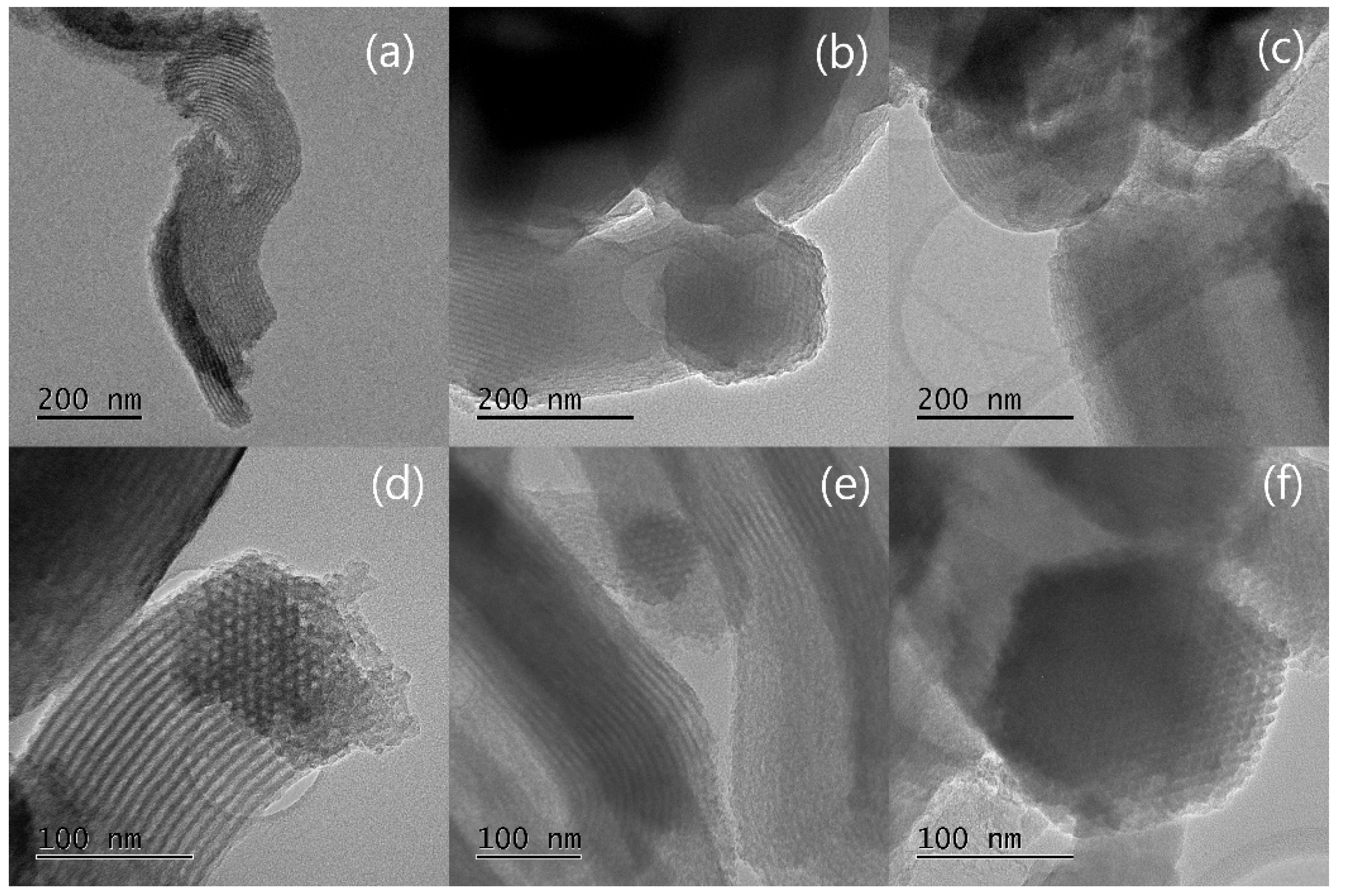
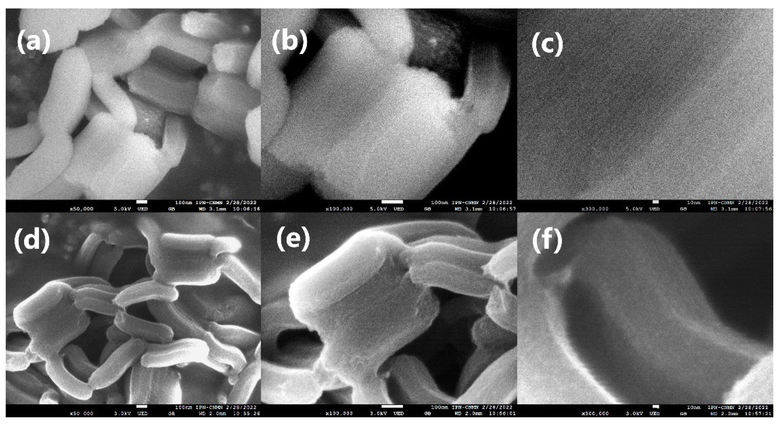
3.1. Morphological Sequence in the CMK-3 Synthesis Stages

For this section, the morphological sequence by TEM starts with SBA-15 images, then the three composite stages, and ends with the CMK-3 micrographs. Figure 2a,b show the images of the particular hexagonal pore arrangement of silica SBA-15 [21,23]; from these images, the pore diameter analysis was performed with image J software, taking the pore measurements in the shaded sections of the hexagonal arrays. The histogram in Figure 2c shows approximate diameters between 6 and 8.5 nm, a wide range for mesopore distribution that will be compared below with the values obtained by the NLDFT method and those calculated from XRD data.
The first “stage of impregnation” corresponds to the hydrolysis of sucrose accompanied by partial polymerization reactions through water evaporation at 273 K using low concentrations of H2SO4 as a catalyst to be distributed. The critical step is that the SBA-15 surface and sucrose carbon source can be partially cross-linked during the acid pre-treatment by eliminating their oxygen atoms in the form of H2O due to the dehydrating catalytic property of sulfuric acid [24]. Then, this impregnation process continues on the surface of the template cylindrical pores at the melting temperature of sucrose at 433 K [25] and where the appearance of graphitic species begins [12] (Figure 3a,d); this process leaves the water space dislodged with a partially polymerized sucrose available for a second impregnation where the temperature ramps are repeated with the carbon source (Figure 3b,e), followed by pyrolysis at 1173 K. Figure 3c,f shows the hexagonal arrangements of the composites made up of SBA-15 silica calcined at 823 K, where its pores are occupied by CMK-3 carbon carbonized at 1173 K.
Finally, in Figure 4, the characteristic structure of the CMK-3 carbons can be seen (Figure 4a,c), where it is observed how their structure is precisely the inverse replica of the SBA-15 template by now showing its arrangement of pores in the reverse color to the matrix (Figure 2a). With this technique, contrary to SEM micrographs, it was possible to visualize the arrangement of “nanopipes” in the direction perpendicular to the pore channels formed in the cavities of the template between 5.5 and 6.5 nm in diameter [26] (Figure 4c). These diameters are smaller than the pore size of the matrix as they have a compacting and sintering effect in the pyrolysis stage of carbon formation.
On the other hand, Figure 4c can be analyzed, assuming a projection of the CMK-3 structure where the precise lines are considered nanopipes. The distance between two of these can be interpreted as projections of the mesopores between two adjacent nanopipes. Considering that the mesopores of CMK-3 do not have a geometrically exact structure but are considered cylindrical pores as they are the inverse replica of silica SBA-15, this could be a reasonable estimate of the diameter of the pores. This consideration has also been used to analyze CMK-5 nanopipes carbons [27]. In addition, the measurements by microscopy provide direct values, where there are no models or assumptions of structure; however, there are different disadvantages, such as the need for a flat cross-section [28], the search for ideal contrast, the correction of aberrations [29], the wide distribution of particle size and pores, and the particle shape factors [30].
High-resolution scanning electron microscopy (HRSEM) micrographs of synthesized SBA-15 silica template and CMK-3 carbon are shown in Figure 5, where images 5a and d show a characteristic rod-like morphology in this type of materials [31,32] at a large scale. Even when the SEM technique has limitations in observing the pore structural order [33], it was possible to visualize the ordered mesopore channels of the SBA-15 sample at ×300,000 (Figure 5c). Meanwhile, the CMK-3 pore system micrograph under the same conditions is unclear due to carbon compaction/sintering in the pyrolysis stage (Figure 5f). The additional point is that Figure 5a,d, show a very similar rod morphology for both SBA-15 and CMK-3 primary particles, which could confirm the absence of sucrose aggregates outside the template and suggest the total sucrose impregnation inside the SBA-15 cylindrical pores.

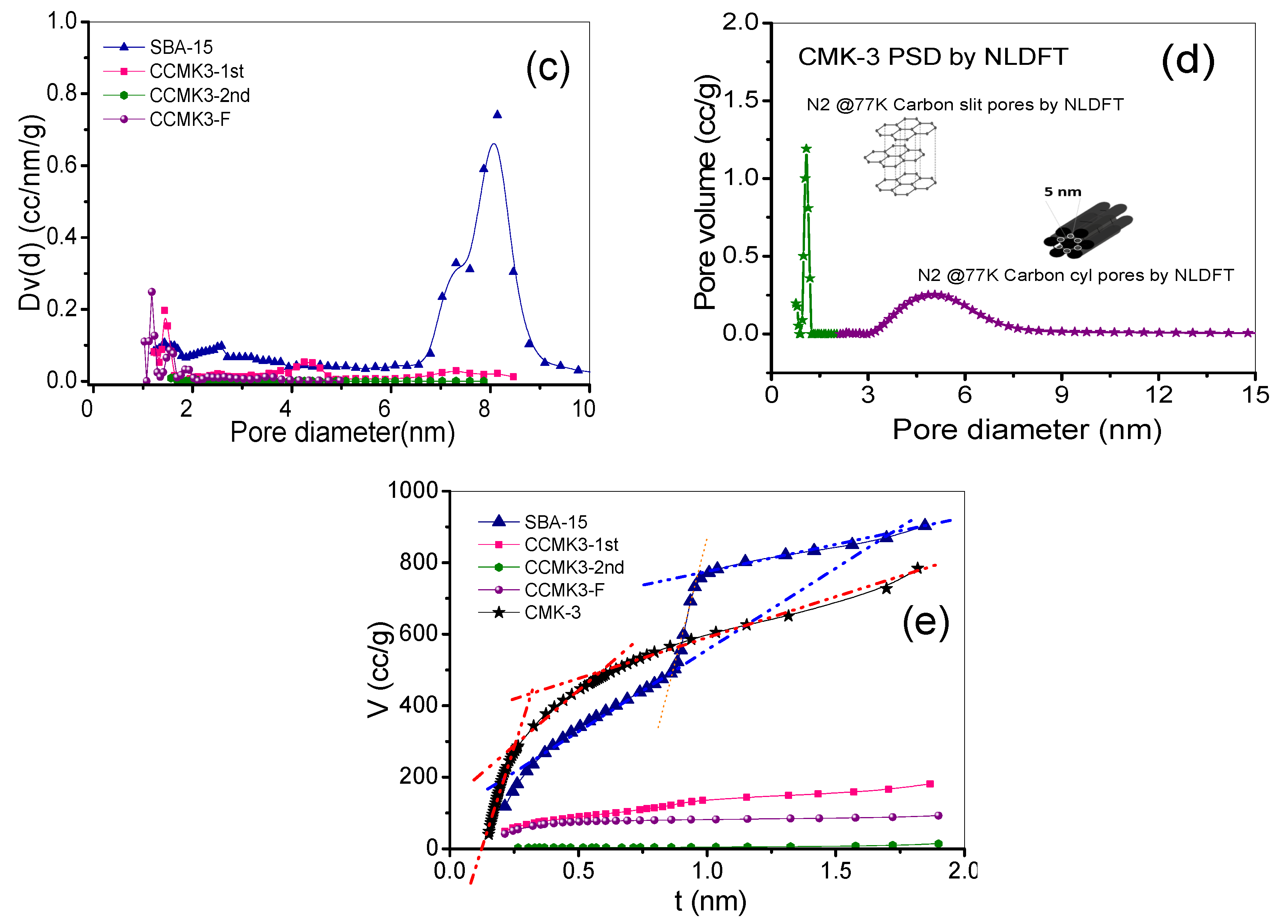
3.2. Textural Behavior for Each Synthesis Stage

According to IUPAC, the texture is defined as the detailed geometry of the porous hollow space of material. This type of characterization allows understanding the types of cavities with an idealized pore geometry, the pore volumes, and the micro- and mesopore pore size distributions throughout the CMK-3 synthesis route, which allows a better understanding of the filling of the cylindrical mesopores of SBA-15 in the synthesis of CMK-3 and the study of the resulting porosity in this type of carbon.
Figure 6 shows the adsorption isotherms of N2 at 77 K, where different types of isotherms and hysteresis loops can be observed in the synthesis stages. First, SBA-15 shows a type IV isotherm with hysteresis loop H1 [28]; this form is widely reported and known in SBA15-type mesoporous materials and is associated with porous systems that consist of cylindrical geometry pores opened by both sides. Variations between methods and synthesis conditions can influence the range of relative pressures where the hysteresis loop appears and, therefore, the diameter of the mesopores of this type of material [34,35,36]. In the first impregnation stage (CCMK3-1st), the decrease in the adsorbed volume from (1) to (2) is visible as the cylindrical mesopores of the matrix are filled with sucrose to a greater extent. A slight increase in volume concerning pressure is observed in the CCMK3-1st isotherm, and a barely noticeable H3-type hysteresis loop still suggests the presence of partially filled mesopores. For the next stage (CCMK3-2nd), the adsorbed volume decreases from (2) to (3) entirely; that is, both the micro- and mesopores of the template were filled with the sucrose/H2SO4 mixture.
Another interesting observation of the isotherm’s behavior is the increase in adsorbed volume in the final pyrolyzed compound compared to the second impregnation. The complete polymerization of sucrose and pyrolysis that gives the formation of carbon [37] leaves microporous spaces corresponding to graphitic slits [13]. This phenomenon is why there is an increase in volume from (3) to (4), where the isotherm of the CCMK3-F composite shows a type I isotherm where the formation of a monolayer occurs at very low pressures and the volume is maintained constant at higher relative pressures. When the silica matrix is removed from (4) to (5), the space occupied by the SBA-15 structure now represents the mesoporous part of the carbon. This fact results in material within the IUPAC classification, as isotherm type IV, with a significant microporosity observed in the large volume adsorbed before the isotherm knee at low pressures [38]. The CMK-3 open hysteresis cycle at the high-pressure (black) isotherm is possibly due to the presence of carbon aggregates that did not remain inside the pores; however, the contribution to the total area of the material is not representative of a significant number of these.
The textural properties of the template, composites, and carbon obtained from the analysis of the adsorption isotherms of N2 at 77 K are shown in Table 1. In this table, the following sequence is observed in descending order of specific surface area (As): CMK-3 > SBA-15 > CCMK3-1st > CCMK3-F > CCMK3-2nd. The second impregnation confirmed the total pore filling, leaving a surface area of 12.5 m2/g, possibly by a complex of composite aggregates in the CCMK3-2nd sample, a minimum figure compared to that obtained in the SBA-15 template (1054 m2/g) and its inverse replica CMK-3 (1350 m2/g). Another interesting fact is the behavior of the pore volume. First, it starts with a total pore volume of 1.32 cm3/g, of which 1.20 cm3/g corresponds to the cylindrical primary mesopores of SBA-15 (Figure 2a) and 0.12 cm3/g to the interconnecting micropores in its structure. Then, when these pores are impregnated with the carbon source the first time (Figure 3a), the total volume decrease to 0.25 cm3/g, leaving free space mainly in the mesoporosity for the second impregnation when the total pore volume drops to 0.01 cm3/g (CCMK3-2nd) (Figure 3b), and finally, when the silica matrix is removed, the mesopore volume of the CMK-3 carbon decreases (1.06 cm3/g) and the micropore has a slight increase (0.16 cm3/g) (Figure 4) compared to the SBA-15 template (Figure 2) (See Figure 1 for a better follow up to the process).

Pore Size Distribution

Figure 7 compares the primary methods for evaluating the distribution of micro- and mesopores. Figure 7a presents the distribution obtained by the classical Barrett–Joyner–Hallenda (BJH) desorption method. The SBA-15 sample shows pore diameters of 6.25 nm, followed by CCMK3-1st, which offers a weak signal at 3.1, representing the SBA-15 unfilled primary mesopores. For both the CCMK3-2nd and CCMK3-F composites, there is no presence of mesoporosity. The CMK-3 carbon presents its first family of mesopores in the 3.4–3.7 nm range. It is complemented by a second family of micropores that gives the highest intensity signal in the D–A graph with a diameter of 1.5 nm (Figure 8b). The BJH method is based on the Kelvin equation, which is known to underestimate approximately 25% in mesopores smaller than 10 nm [38,39], which explains the higher values obtained from non-localized density functional theory (NLDFT). This method allowed us to know the micro and mesopore families with a single function with families of 1.4 and 8.1 nm for SBA-15 (NLDFT equilibrium model N2 77 K on silica). For the calculation of the composites CCMK-1st, CCMK-2nd, and CCMK3-F, the N2 77 K on carbon NLDFT model was applied to assume carbon slit-shaped pores. To apply the NLDFT model to the CMK-3 sample, two different kernels were used. In the first one, at very low relative pressures (1 × 10⁻⁵–1 × 10⁻²), where the volumetric micropore filling is carried out, the N2 77 K carbon slit pores model was applied, obtaining a 1.2 nm micropore size. The second one was analyzed at relative pressures above 1 × 10⁻² using an N2 77 K carbon cylindrical pores model. The combination of these two models allows the bimodal micro- and mesopore size distribution centered at 1.2 and 5 nm (Figure 7d). These values are consistent with other reported values, where the new Quenched Solid Density Functional Theory Method (QSDFT) for cylindrical pores was applied for similar CMK-3 carbons [40]. For both materials (SBA-15 and CMK-3), the mesopore diameters were located at the ends of the intervals estimated qualitatively by TEM (Figure 2 and Figure 4).
Finally, the t-plot represents the statistical thickness of the adsorbed layer (based on the de Boer equation) (Figure 7e). For the SBA-15 template, three regions are mainly observed. The first corresponds to the filling of the interconnecting micropores, and the second occurs before capillary condensation, where the filling of mesopores is completed, and the beginning of adsorption on the external surface starts. Finally, the last one is above condensation, where adsorption only appears on the external surface of the particles [41]. The CMK-3 t-plot has three different inflections with linear segments (dotted red lines) corresponding to (1) volumetric filled inside the super-micropores and micropores, (2) the filling of the mesoporous before capillary condensation, and (3) the adsorption in the external surface [42]. Although, in this last case, the adsorption process is a little more complex than the process that occurs in the silica matrix, reflected in the t-plot form where there is not a precise inflection and follows a curve behavior, due to the non-geometrical pores formed by the interconnection of three nanopipes, and which for practical terms are considered as cylindrical mesopores.

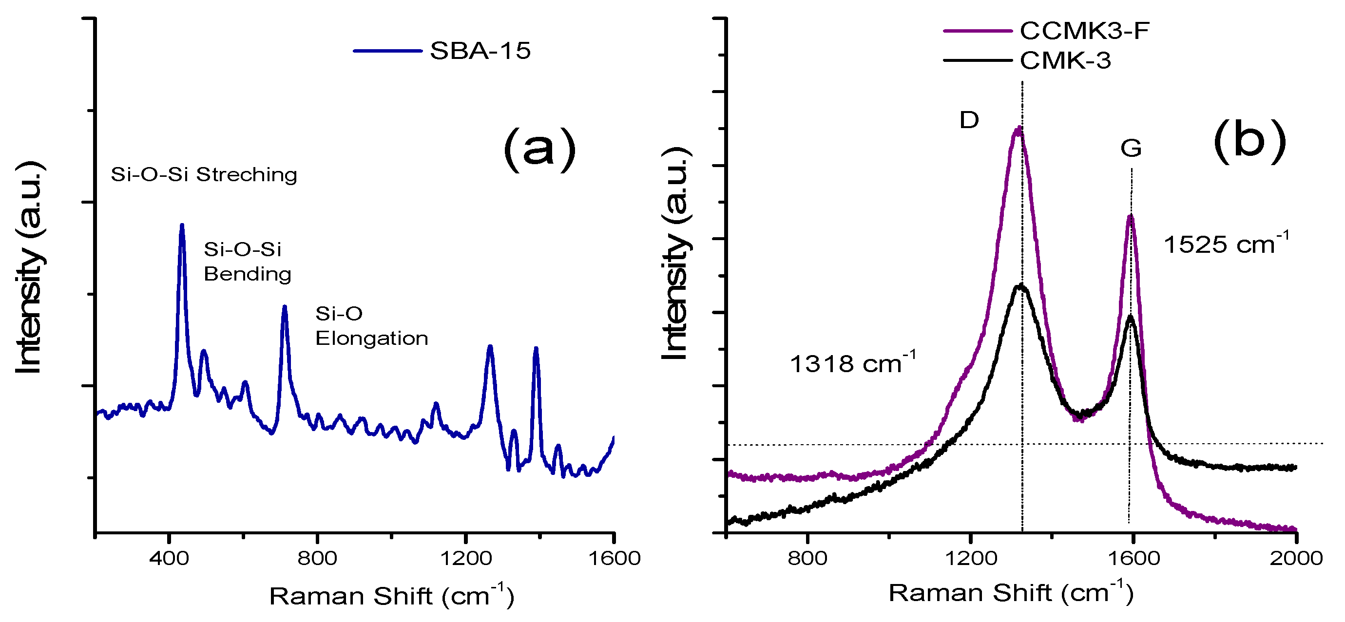
3.3. Additional Structural Characterization of SBA-15 Template, and CMK-3 Mesoporous Carbon

The X-ray diffraction patterns of SBA-15 and CMK-3 collected at a small angle are shown in Figure 8. The low-angle pattern of the SBA-15 template shows a well-defined signal at 0.9 (2Θ) for the (100) plane and the two secondary (110) and (200) diffractions of the 2-d hexagonal space group (P6mm) [5], which is indicative of an excellent structural order [43]. Their inverse replica CMK-3 was confirmed with the presence of the signal at d(100) = 8.4 nm [11].
Considering the interplanar distances equals 9.3 nm for the SBA-15 signal, 8.4 nm for CMK-3, and the micro and mesopore volumes obtained from N2 isotherms, the SBA-15 (Equation (1)) and CMK-3 (Equation (3)) mesopore diameters were calculated. Also, the WCMK-3 nanopipe was estimated with Equation (2). Under these considerations, the SBA-15 mesopore diameter (Wd) equals 7.6 nm, the WCMK-3 mesopore diameter is 4.9 nm, and WCMK-3 nanopipe = 6.3 nm. In addition to small angle XRD diffractograms, Figure 8 shows a hexagonally 2-D cross-section for CMK-3 carbons [22].
In summary, Table 2 shows the mesopore and nanopipe sizes of SBA-15 and CMK-3 samples for the mentioned methods. Where XRD calculations are consistent with the obtained by the NLDFT method in the N2 isotherms analysis, and both drops in the histograms intervals obtained by the processing of TEM images with an apparent deviation to the upper limit.
Finally, additional data were obtained from Raman spectra. In the case of SBA-15, the Raman spectrum (Figure 9a) shows the characteristic signals of Si-O-Si stretching, Si-O-Si bending, and Si-O elongation vibrations [44]. Meanwhile, Figure 9b shows the D and G bands at 1318 and 1525 cm1 for CMK-3 carbon. The first signal corresponds to the disordered or amorphous carbon structure (D), representing the second maximum in the graphite vibrational density in small graphitic crystallites [45]. The second one is those assigned to interplane sp2 -hybridized graphitic hexagonal carbon sheet (G), respectively [46], resulting from the final pyrolysis processes of the CMK3-F composite. The calculated CMK-3 ID/IG ratio shows a low graphitization degree with a 1.16 value [47] and has been associated with silica/carbon source ratio [45] and carbonization temperature [5]. This phenomenon could be why the CMK-3 sample presents a small micropore volume representing the space between graphitic layers. This study is not feasible for the intermediate composites since they are composed of complex polymers that would present abundant vibrations and signals.

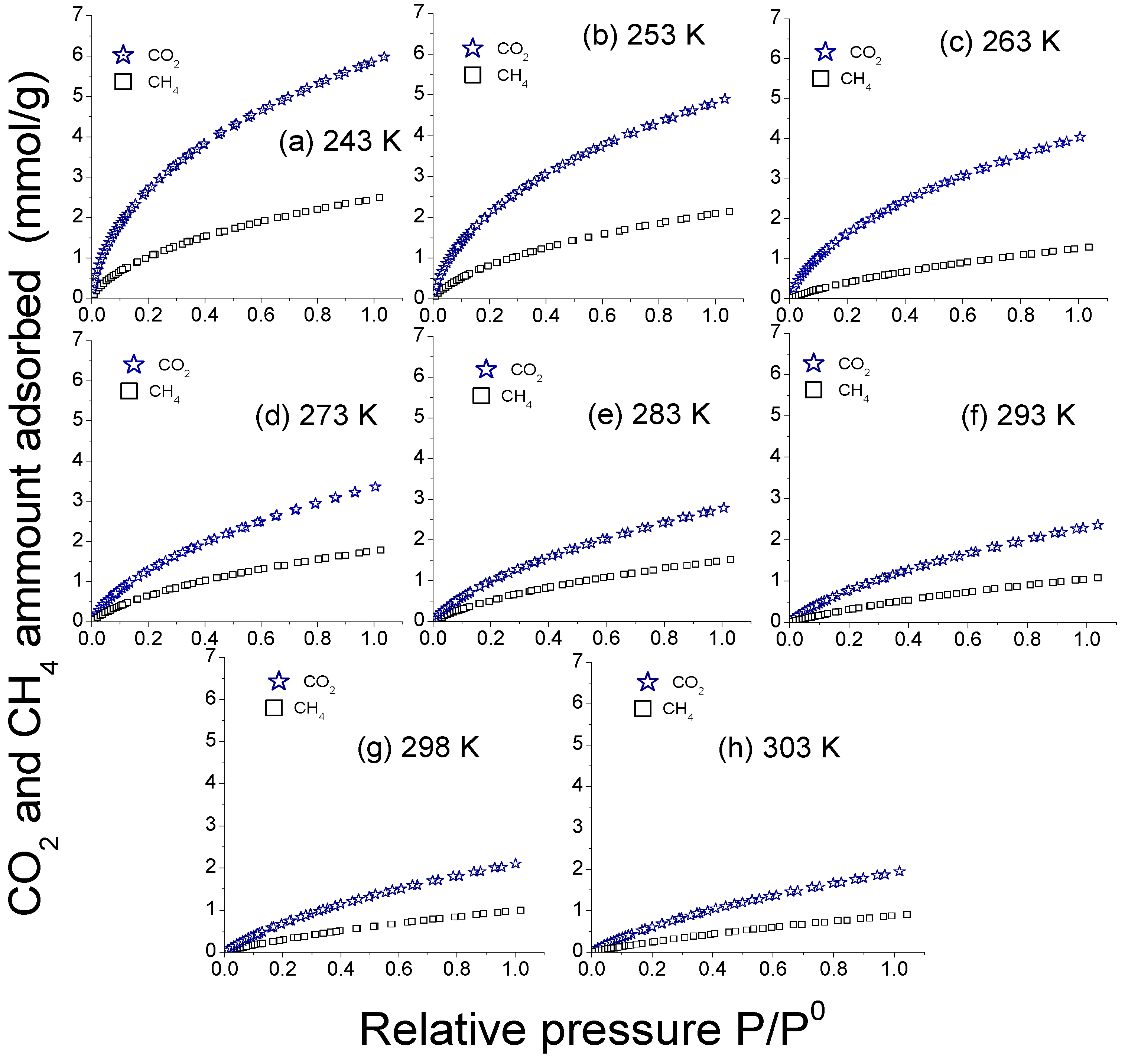
3.4. Evaluation of the CO2 and CH4 Adsorption

CO2 and CH4 Adsorption Selectivity and Isosteric Enthalpy Behavior

Figure 10 presents the adsorption isotherms of CO2 and CH4 comparatively by temperature. In general, there is a preference for CO2 adsorption over CH4 due to the lower pore diameter of the CO2 molecule and the presence of its quadrupole moment that generates greater interactions between the carbon surface and the CO2 molecules [20] (Table 3), in addition to the decrease in adsorption with increasing temperature. The maximum CO2 adsorption capacity at 243 K was 6 mmol/g; meanwhile, at 273 K, the obtained value was 3.4 mmol/g. The result obtained by the synthesized CMK-3 carbon is higher than some similar CMK-3 materials without activation treatments, reporting values of 3.2 mmol/g [9], ordered mesoporous carbons (3 mmol/g) [48], and mesoporous carbons nitrides with a value around 2.0 mmol/g [49] reported for CO2 adsorption, considering the same operating conditions, as well as for different synthetic materials such as nanoparticles of zeolite type T [50], zeolite 13X [51], MCM-41 [52], SBA-15 [53], graphene nanocomposites with Fe3O4 [54], and others.
These graphs’ corresponding calculations were made to determine the ideal selectivity of CO2:CH4 given in the carbon CMK-3 (Figure 11b).
The evolution of the isosteric enthalpy of the adsorption of CO2 and CH4 was calculated by applying the Clausius–Clapeyron equation, shown in Figure 11. In the case of CO2, it is observed that there is a slight dependence of the isosteric enthalpy with the amount adsorbed in the coverage range of 0–2 mmol/g of CO2 adsorbed, which gives us strong energetically homogeneous interactions on microporous surfaces that generate lateral interactions between CO2 molecules [55]. This last behavior is shared for CH4, but the interactions correspond to London dispersion forces. Finally, it can be seen that the isosteric enthalpies of adsorption show values above the CO2 and CH4 heat of liquefaction [56], which means strong interactions between adsorbate molecules. On the other hand, in Figure 11b, a binary concentration of 70% CH4 and 30% CO2 was assumed, which is a representative mixture of natural gas [51]. The ideal selectivity shows a maximum value of 5.6 at 243 K, which decreases about 12% until 4.9 at 298 K. This behavior agrees with the amount of CO2 and CH4 adsorbed (Figure 10).

4. Conclusions

The investigation allowed us to better understand the textural and morphological changes in the formation of micro- and mesoporosity of CMK-3 carbon in each synthesis stage. Even when it is known that the CMK-3 carbon is an inverse replica of the SBA-15 silica, the textural analysis revealed a little increase in microporosity in the pyrolysis stage, corresponding to the beginning of the formation of graphitic slits, confirmed by Raman for the CCMK3-F composite and the CMK-3 structural order by XRD at a low angle. The textural monitoring of pore filling by N2 adsorption, not only in the synthesis of CMK-3 but also in any stepwise synthesis using a template, can be a viable method for controlling synthesis conditions and concentrations.
The combination of carbon slit and cylindrical models to NLDFT for the respective micro- and mesoporous pressure intervals shows the best pore size distribution for the CMK-3 sample, with a bimodal pore size distribution centered at 1.2 and 8 nm, which is consistent with XRD data and within the interval obtained by processing TEM images. Therefore, the pore size distribution by NLDFT and textural analysis are more feasible and give better information about the pore filling than microscopy. Furthermore, N2 adsorption experiments use a more representative fraction of the sample. Thus, the information provided by this technique is much more reliable.
The material synthesized and studied in its impregnation stages presented CO2 adsorption values of up to 6 mmol/g at 243 K. The behavior of both CO2 and CH4 adsorption enthalpies showed strong intermolecular interactions reflected in high selectivity values for an ideal mixture of CO2:CH4 (30:70%), which could even be improved under activation and/or functionalization treatments.

Author Contributions

Conceptualization, K.Q.-E. and M.E.-S.; methodology, K.Q.-E. and M.E.-S.; formal analysis, K.Q.-E., M.E.-S. and C.F.; investigation, K.Q.-E. and M.E.-S., resources, K.Q.-E., M.E.-S. and C.F.; writing—original draft preparation, K.Q.-E.; writing—review and editing, K.Q.-E., M.E.-S. and C.F.; visualization, K.Q.-E. and M.E.-S.; supervision, M.E.-S. All authors have read and agreed to the published version of the manuscript.

Funding

This research was supported by a Postdoctoral Research Scholarship–CONACYT, CVU-No. 553758 and the project (i) SIP-IPN 20221600 “Procesos Capilares en Materiales Nanoporosos: un Estudio Experimental y de Simulación (parte 2)”.

Acknowledgments

We thank the “Electrochemistry area” of the UAM-I for the instruments provided. The experimental support provided by the CNMN-IPN is also acknowledge.

Conflicts of Interest

The authors declare no conflict of interest.

References

  1. Marcos-Hernández, M.; Villagrán, D. 11—Mesoporous Composite Nanomaterials for Dye Removal and Other Applications. In Micro and Nano Technologies; Kyzas, G.Z., Mitropoulos, A.C., Eds.; Elsevier: Amsterdam, The Netherlands, 2019; pp. 265–293. ISBN 978-0-12-814132-8. [Google Scholar]
  2. Benzigar, M.R.; Talapaneni, S.N.; Joseph, S.; Ramadass, K.; Singh, G.; Scaranto, J.; Ravon, U.; Al-Bahily, K.; Vinu, A. Recent advances in functionalized micro and mesoporous carbon materials: Synthesis and applications. Chem. Soc. Rev. 2018, 47, 2680–2721. [Google Scholar] [CrossRef]
  3. Yuan, H.; Jin, B.; Meng, L.Y. Effect of the SBA-15 template and KOH activation method on CO2 adsorption by N-doped polypyrrole-based porous carbons. Carbon Lett. 2018, 28, 116–120. [Google Scholar] [CrossRef]
  4. Venosta, L.F.; Juárez, J.M.; Anunziata, O.A.; Bercoff, P.G.; Gómez Costa, M.B. Synthesis and characteristics of CMK-3 modified with magnetite nanoparticles for application in hydrogen storage. J. Nanopart. Res. 2020, 22, 227. [Google Scholar] [CrossRef]
  5. Montiel-Centeno, K.; Barrera, D.; Villarroel-Rocha, J.; Arroyo-Gómez, J.J.; Moreno, M.S.; Sapag, K. CMK-3 nanostructured carbon: Effect of temperature and time carbonization on textural properties and H2 storage. Chem. Eng. Commun. 2019, 206, 1581–1595. [Google Scholar] [CrossRef]
  6. Jarczewski, S.; Drozdek, M.; Michorczyk, P.; Cuadrado-Collados, C.; Gandara-Loe, J.; Silvestre-Albero, J.; Kuśtrowski, P. Oxidative dehydrogenation of ethylbenzene over CMK-1 and CMK-3 carbon replicas with various mesopore architectures. Microporous Mesoporous Mater. 2018, 271, 262–272. [Google Scholar] [CrossRef]
  7. Janus, P.; Janus, R.; Dudek, B.; Drozdek, M.; Silvestre-Albero, A.; Rodríguez-Reinoso, F.; Kuśtrowski, P. On mechanism of formation of SBA-15/furfuryl alcohol-derived mesoporous carbon replicas and its relationship with catalytic activity in oxidative dehydrogenation of ethylbenzene. Microporous Mesoporous Mater. 2020, 299, 110118. [Google Scholar] [CrossRef]
  8. Yun, L.; Gao, Z.; Cheng, X.; Li, P.; Wang, L.; Guo, N.; Luo, C.; Zhu, X.; Liu, B.; Wu, D.; et al. Effect of peroxydisulfate oxidation catalyzed with ordered mesoporous carbons on controlling ultrafiltration membrane fouling by algal organic matter. Chemosphere 2022, 303, 135037. [Google Scholar] [CrossRef]
  9. Sevilla, M.; Fuertes, A.B. CO2 adsorption by activated templated carbons. J. Colloid Interface Sci. 2012, 366, 147–154. [Google Scholar] [CrossRef] [Green Version]
  10. Hwang, C.-C.; Jin, Z.; Lu, W.; Sun, Z.; Alemany, L.B.; Lomeda, J.R.; Tour, J.M. In situ Synthesis of Polymer-Modified Mesoporous Carbon CMK-3 Composites for CO2 Sequestration. ACS Appl. Mater. Interfaces 2011, 3, 4782–4786. [Google Scholar] [CrossRef]
  11. Jun, S.; Joo, S.H.; Ryoo, R.; Kruk, M.; Jaroniec, M.; Liu, Z.; Ohsuna, T.; Terasaki, O. Synthesis of New, Nanoporous Carbon with Hexagonally Ordered Mesostructure. J. Am. Chem. Soc. 2000, 122, 10712–10713. [Google Scholar] [CrossRef]
  12. Xu, Q.; Hu, X.; Shao, Y.; Sun, K.; Jia, P.; Zhang, L.; Liu, Q.; Wang, Y.; Hu, S.; Xiang, J. Structural differences of the soluble oligomers and insoluble polymers from acid-catalyzed conversion of sugars with varied structures. Carbohydr. Polym. 2019, 216, 167–179. [Google Scholar] [CrossRef] [PubMed]
  13. Solovyov, L.A.; Shmakov, A.N.; Zaikovskii, V.I.; Joo, S.H.; Ryoo, R. Detailed structure of the hexagonally packed mesostructured carbon material CMK-3. Carbon 2002, 40, 2477–2481. [Google Scholar] [CrossRef]
  14. Wang, X.; Liang, C.; Dai, S. Nano/Microporous Materials: Mesoporous and Surface-Functionalized Mesoporous Carbon. Encycl. Inorg. Chem. 2009.
  15. Olchowski, R.; Dobrowolski, R. Synthesis, properties and applications of CMK-3-type ordered mesoporous carbons. Ann. Univ. Mariae Curie-Sklodowska Sect. AA–Chem. 2018, 73, 11–30. [Google Scholar] [CrossRef]
  16. Zhou, J.; Su, W.; Sun, Y.; Deng, S.; Wang, X. Enhanced CO2 Sorption on Ordered Mesoporous Carbon CMK-3 in the Presence of Water. J. Chem. Eng. Data 2016, 61, 1348–1352. [Google Scholar] [CrossRef]
  17. Lakhi, K.S.; Cha, W.S.; Choy, J.-H.; Al-Ejji, M.; Abdullah, A.M.; Al-Enizi, A.M.; Vinu, A. Synthesis of mesoporous carbons with controlled morphology and pore diameters from SBA-15 prepared through the microwave-assisted process and their CO2 adsorption capacity. Microporous Mesoporous Mater. 2016, 233, 44–52. [Google Scholar] [CrossRef]
  18. Ojeda-López, R.; Vilarrasa-García, E.; Azevedo, D.C.; Felipe, C.; Cecilia, J.A.; Rodríguez-Castellón, E. CO2 selectivity in CO2:CH4 and CO2:N2 mixtures on carbon microfibers (CMFs) and carbon microspheres (CMSs). Fuel 2022, 324, 124242. [Google Scholar] [CrossRef]
  19. Varghese, A.M.; Karanikolos, G.N. CO2 capture adsorbents functionalized by amine—Bearing polymers: A review. Int. J. Greenh. Gas Control 2020, 96, 103005. [Google Scholar] [CrossRef]
  20. Alonso, A.; Moral-Vico, J.; Abo Markeb, A.; Busquets-Fité, M.; Komilis, D.; Puntes, V.; Sánchez, A.; Font, X. Critical review of existing nanomaterial adsorbents to capture carbon dioxide and methane. Sci. Total Environ. 2017, 595, 51–62. [Google Scholar] [CrossRef] [Green Version]
  21. Ojeda-López, R.; Pérez-Hermosillo, I.J.; Marcos Esparza-Schulz, J.; Cervantes-Uribe, A.; Domínguez-Ortiz, A. SBA-15 materials: Calcination temperature influence on textural properties and total silanol ratio. Adsorption 2015, 21, 659–669. [Google Scholar] [CrossRef]
  22. Joo, S.H.; Ryoo, R.; Kruk, M.; Jaroniec, M. Evidence for General Nature of Pore Interconnectivity in 2-Dimensional Hexagonal Mesoporous Silicas Prepared Using Block Copolymer Templates. J. Phys. Chem. B 2002, 106, 4640–4646. [Google Scholar] [CrossRef]
  23. Esparza, J.M.; Ojeda, M.L.; Campero, A.; Domínguez, A.; Kornhauser, I.; Rojas, F.; Vidales, A.M.; López, R.H.; Zgrablich, G. N2 sorption scanning behavior of SBA-15 porous substrates. Colloids Surf. A Physicochem. Eng. Asp. 2004, 241, 35–45. [Google Scholar] [CrossRef]
  24. Li, L.; Song, H.; Chen, X. Ordered mesoporous carbons from the carbonization of sulfuric-acid-treated silica/triblock copolymer/sucrose composites. Microporous Mesoporous Mater. 2006, 94, 9–14. [Google Scholar] [CrossRef]
  25. National Center for Biotechnology Information Sucrose. Available online: https://pubchem.ncbi.nlm.nih.gov/compound/Sucrose (accessed on 4 August 2022).
  26. Farzin Nejad, N.; Shams, E.; Amini, M.K.; Bennett, J.C. Ordered mesoporous carbon CMK-5 as a potential sorbent for fuel desulfurization: Application to the removal of dibenzothiophene and comparison with CMK-3. Microporous Mesoporous Mater. 2013, 168, 239–246. [Google Scholar] [CrossRef]
  27. Kruk, M.; Jaroniec, M.; Kim, T.-W.; Ryoo, R. Synthesis and Characterization of Hexagonally Ordered Carbon Nanopipes. Chem. Mater. 2003, 15, 2815–2823. [Google Scholar] [CrossRef]
  28. Espinal, L. Porosity and Its Measurement. In Characterization of Materials; Wiley Online Library: Hoboken, NJ, USA, 2012; pp. 1–10. ISBN 9780471266969. [Google Scholar]
  29. Smith, D.J. Chapter 1: Characterization of Nanomaterials Using Transmission Electron Microscopy. In Nanocharacterisation (2); The Royal Society of Chemistry: London, UK, 2015; pp. 1–29. ISBN 978-1-84973-805-7. [Google Scholar]
  30. Rouquerol, F.; Rouquerol, J.; Sing, K.S.W.; Llewellyn, P.; Maurin, G. Adsorption by Powders and Porous Solids: Principles, Methodology and Applications; Elsevier: Amsterdam, The Netherlands, 2014; ISBN 978-0-08-097035-6. [Google Scholar]
  31. Barrera, D.; Dávila, M.; Cornette, V.; de Oliveira, J.C.A.; López, R.H.; Sapag, K. Pore size distribution of ordered nanostructured carbon CMK-3 by means of experimental techniques and Monte Carlo simulations. Microporous Mesoporous Mater. 2013, 180, 71–78. [Google Scholar] [CrossRef]
  32. Yu, C.; Fan, J.; Tian, B.; Zhao, D.; Stucky, G.D. High-Yield Synthesis of Periodic Mesoporous Silica Rods and Their Replication to Mesoporous Carbon Rods. Adv. Mater. 2002, 14, 1742–1745. [Google Scholar] [CrossRef]
  33. Hiraide, S.; Yamada, M.; Kataoka, S.; Inagi, Y.; Endo, A. Time evolution of the framework structure of SBA-15 during the aging process. Colloids Surf. A Physicochem. Eng. Asp. 2019, 583, 123807. [Google Scholar] [CrossRef]
  34. Aguilar García, E.; Cruz, M.S.; Madeira, H.Y.; Huesca, R.H.; Cruz, M.A.P. Synthesis of Fe Catalysts Doped in SBA-15 by EISA Method: Characterization and Catalytic Studies in 2-Propanol Decomposition. Kinet. Catal. 2021, 62, S38–S47. [Google Scholar] [CrossRef]
  35. Barrera, D.; Villarroel-Rocha, J.; Marenco, L.; Oliva, M.I.; Sapag, K. Non-Hydrothermal Synthesis of Cylindrical Mesoporous Materials: Influence of the Surfactant/Silica Molar Ratio. Adsorpt. Sci. Technol. 2011, 29, 975–988. [Google Scholar] [CrossRef]
  36. Santos, S.M.L.; Cecilia, J.A.; Vilarrasa-García, E.; Silva Junior, I.J.; Rodríguez-Castellón, E.; Azevedo, D.C.S. The effect of structure modifying agents in the SBA-15 for its application in the biomolecules adsorption. Microporous Mesoporous Mater. 2016, 232, 53–64. [Google Scholar] [CrossRef]
  37. Chen, H.; Dou, B.; Song, Y.; Xu, Y.; Zhang, Y.; Wang, C.; Zhang, X.; Tan, C. Pyrolysis characteristics of sucrose biomass in a tubular reactor and a thermogravimetric analysis. Fuel 2012, 95, 425–430. [Google Scholar] [CrossRef]
  38. Thommes, M.; Kaneko, K.; Neimark, A.V.; Olivier, J.P.; Rodriguez-Reinoso, F.; Rouquerol, J.; Sing, K.S.W. Physisorption of gases, with special reference to the evaluation of surface area and pore size distribution (IUPAC Technical Report). Pure Appl. Chem. 2015, 87, 1051–1069. [Google Scholar] [CrossRef] [Green Version]
  39. Thommes, M. Physical adsorption characterization of ordered and amorphous mesoporous materials. In Nanoporous Materials: Science and Engineering; Series on Chemical Engineering; World Scientific: Singapore, 2004; Volume 4, pp. 317–364. ISBN 978-1-86094-210-5. [Google Scholar]
  40. Thommes, M.; Morell, J.; Cychosz, K.A.; Fröba, M. Combining Nitrogen, Argon, and Water Adsorption for Advanced Characterization of Ordered Mesoporous Carbons (CMKs) and Periodic Mesoporous Organosilicas (PMOs). Langmuir 2013, 29, 14893–14902. [Google Scholar] [CrossRef]
  41. Galarneau, A.; Villemot, F.; Rodriguez, J.; Fajula, F.; Coasne, B. Validity of the t-plot Method to Assess Microporosity in Hierarchical Micro/Mesoporous Materials. Langmuir 2014, 30, 13266–13274. [Google Scholar] [CrossRef]
  42. Lysenko, N.D.; Yaremov, P.S.; Shvets, A.V.; Il’in, V.G. Effect of the chemical and structural modification of CMK-3 mesoporous carbon molecular sieve on hydrogen adsorption. Theor. Exp. Chem. 2009, 45, 380–385. [Google Scholar] [CrossRef]
  43. Juárez, J.M.; Gómez Costa, M.B.; Anunziata, O.A. Synthesis and characterization of Pt-CMK-3 hybrid nanocomposite for hydrogen storage. Int. J. Energy Res. 2015, 39, 128–139. [Google Scholar] [CrossRef]
  44. Medina-Juárez, O.; García-Sánchez, M.Á.; Arellano-Sánchez, U.; Kornhauser-Straus, I.; Rojas-González, F. Optimal Surface Amino-Functionalization Following Thermo-Alkaline Treatment of Nanostructured Silica Adsorbents for Enhanced CO2 Adsorption. Materials 2016, 9, 898. [Google Scholar] [CrossRef] [Green Version]
  45. Vinu, A.; Srinivasu, P.; Takahashi, M.; Mori, T.; Balasubramanian, V.V.; Ariga, K. Controlling the textural parameters of mesoporous carbon materials. Microporous Mesoporous Mater. 2007, 100, 20–26. [Google Scholar] [CrossRef]
  46. Qiu, Y.; Huo, J.; Jia, F.; Shanks, B.H.; Li, W. N- and S-doped mesoporous carbon as metal-free cathode catalysts for direct biorenewable alcohol fuel cells. J. Mater. Chem. A 2016, 4, 83–95. [Google Scholar] [CrossRef] [Green Version]
  47. Thu Hang, L.T.; Bich Thuy, H.T. Enhancement in Graphitization of Ordered Mesoporous Carbon by Assistance of Soybean Oil Surfactant. VNU J. Sci. Nat. Sci. Technol. 2020, 36, 17–23. [Google Scholar] [CrossRef]
  48. Yuan, B.; Wu, X.; Chen, Y.; Huang, J.; Luo, H.; Deng, S. Adsorption of CO2, CH4, and N2 on Ordered mesoporous carbon: Approach for greenhouse gases capture and biogas upgrading. Environ. Sci. Technol. 2013, 47, 10. [Google Scholar] [CrossRef]
  49. Lakhi, K.S.; Baskar, A.V.; Zaidi, J.S.M.; Al-Deyab, S.S.; El-Newehy, M.; Choy, J.-H.; Vinu, A. Morphological control of mesoporous CN based hybrid materials and their excellent CO2 adsorption capacity. RSC Adv. 2015, 5, 40183–40192. [Google Scholar] [CrossRef] [Green Version]
  50. Jiang, Q.; Rentschler, J.; Sethia, G.; Weinman, S.; Perrone, R.; Liu, K. Synthesis of T-type zeolite nanoparticles for the separation of CO2/N2 and CO2/CH4 by adsorption process. Chem. Eng. J. 2013, 230, 380–388. [Google Scholar] [CrossRef]
  51. Moura, P.A.S.; Bezerra, D.P.; Vilarrasa-Garcia, E.; Bastos-Neto, M.; Azevedo, D.C.S. Adsorption equilibria of CO2 and CH4 in cation-exchanged zeolites 13X. Adsorption 2016, 22, 71–80. [Google Scholar] [CrossRef]
  52. Belmabkhout, Y.; De Weireld, G.; Sayari, A. Amine-Bearing Mesoporous Silica for CO2 and H2S Removal from Natural Gas and Biogas. Langmuir 2009, 25, 13275–13278. [Google Scholar] [CrossRef]
  53. Bhagiyalakshmi, M.; Lee, J.Y.; Jang, H.T. Synthesis of mesoporous magnesium oxide: Its application to CO2 chemisorption. Int. J. Greenh. Gas Control 2010, 4, 51–56. [Google Scholar] [CrossRef]
  54. Mishra, A.K.; Ramaprabhu, S. Enhanced CO2 capture in Fe3O4-graphene nanocomposite by physicochemical adsorption. J. Appl. Phys. 2014, 116, 64306. [Google Scholar] [CrossRef]
  55. Sing, K.S.W.; Ramakrishna, V.R. The role of the isosteric heat of adsorption in the characterization of solid surfaces. Colloq. Int. du CNRS 1971, 201, 431. [Google Scholar]
  56. Reid, R.C.; Prausnitz, J.M.; Poling, B.E. The Properties of Gases and Liquids; McGraw-Hill Chemical Engineering Series; McGraw-Hill: New York, NY, USA, 1987; ISBN 9780070517998. [Google Scholar]
Figure 1. Synthesis route of CMK-3 carbon by hard template method.
Jcs 06 00344 g001
Figure 2. (a,b) HRTEM micrographs of SBA-15 sample and (c) SBA-15 pore diameter histogram.
Jcs 06 00344 g002
Figure 3. HRTEM micrographs of (a,d) CCMK3-1st, (b,e) CCMK3-2nd, and (c,f) CCMK3-F.
Jcs 06 00344 g003
Figure 4. (a,c) HRTEM micrographs of CMK-3 sample, (b) CMK-3 nanopipe diameter histogram and (d) CMK-3 pore diameter histogram.
Jcs 06 00344 g004
Figure 5. HRSEM micrographs of (a) SBA-15 ×50,000, (b) SBA-15 ×100,000, (c) SBA-15 ×300,000, (d) CMK-3 ×50,000, (e) CMK-3 ×100,000, and (f) CMK-3 ×300,000.
Jcs 06 00344 g005
Figure 6. N2 adsorption isotherms of each stage of the CMK-3 synthesis process. Where (1-5) represent the N2 adsorption volume changes between SBA-15, CMK-3, and its intermediate composites.
Jcs 06 00344 g006
Figure 7. Pore size distribution in each stage of the CMK-3 synthesis process by (a) BJH, (b) D–A, (c) NLDFT, (d) CMK3 PSD by NLDFT using a N2@77K Carbon slit pores model (green) and N2@77K Carbon cylindrical pores model (purple), and (e) t-plot where dotted red and blue lines represent different inflections with linear segments in the pores filling.
Jcs 06 00344 g007aJcs 06 00344 g007b
Figure 8. (a) X-ray diffraction pattern of SBA-15 template and CMK-3 carbon and (b) 2-D cross-section representation for a hexagonally ordered structure.
Jcs 06 00344 g008
Figure 9. Raman spectra of (a) SBA-15 and (b) CCMK3-F composite and CMK-3 carbon.
Jcs 06 00344 g009
Figure 10. Comparative of CO2 and CH4 adsorption on CMK-3 at different temperatures.
Jcs 06 00344 g010
Figure 11. (a) Adsorption Isosteric enthalpy behavior of CO2 and CH4 at the interval range of 243–303 K and (b) Ideal selectivity behavior of CO2:CH4 concerning the temperature at relative pressure p/p0 = 1.
Jcs 06 00344 g011
Table 1. Textural parameters of each stage of the CMK-3 synthesis process.
SBA-15CCMK3-1stCCMK3-2ndCCMK3-F CMK-3
AsBET (m2/g)105430712.5266.71350
CBET50284412814291121
Vt (cm3/g)1.320.250.010.131.22
Vmicro (cm3/g) 0.120.08-0.090.16
Vmeso1.200.170.010.041.06
PSD BJH (nm)6.253.1, 5.7-3.43.4–3.7
PSD DA (nm)1.71.41.71.41.4
PSD NLDFT (nm) 1.4, 8.11.4, 4.21.61.21.2, 5
AsBET ≡ BET specific surface area calculated for the interval analysis of p/p0 = 0.0001–0.1; CBET = BET constant, Vt ≡ total pore volume using a Gurvich rule at p/p0 = 0.95; Vmicro ≡ micropore volume by t-plot micropore analysis, Vmeso ≡ mesopore volume, BJH= Barret–Joyner–Hallenda mesopore size distribution method, DA = Dubinin–Astakhov micropore size distribution method, and Non Linear Density Functional Theory method (NLDFT).
Table 2. Comparative table between mesopore analysis methods.
SBA-15 Mesopore Diameter (nm)CMK-3 Mesopore Diameter (nm)CMK-3 Nanopipe Diameter (nm)
TEM Analysis (Histograms) 6–8.5 3.5–5.55–7
N2 Adsorption (NLDFT)8.15-
XRD data7.64.96.28
Table 3. Properties of CO2 and CH4.
Molecule Adsorbed Kinetic Diameter, nmPolarizability, 10−24 cm3Quadrupole, A3
CO20.331.90.64
CH40.382.6-
Publisher’s Note: MDPI stays neutral with regard to jurisdictional claims in published maps and institutional affiliations.

