Article

Analysis of the Segregation Phenomena of Wood Fiber Reinforced Plastics

Kunststofftechnik Paderborn (KTP), Paderborn University, 33098 Paderborn, Germany
*
Authors to whom correspondence should be addressed.
J. Compos. Sci. 2022, 6(10), 321; https://doi.org/10.3390/jcs6100321
Submission received: 7 September 2022 / Revised: 13 October 2022 / Accepted: 19 October 2022 / Published: 20 October 2022
(This article belongs to the Special Issue Wood-Polymer Composites)

Abstract

:
Wood–plastic composites (WPC) are enjoying a steady increase in popularity. In addition to the extrusion of decking boards, the material is also used increasingly in injection molding. Depending on the formulation, geometry and process parameters, WPC tends to exhibit irregular filling behavior, similar to the processing of thermosets. In this work, the influence of matrix material and wood fiber content on the flow, mold filling and segregation behavior of WPC is analyzed. For this purpose, investigations were carried out on a flow spiral and a sheet cavity. WPC based on thermoplastic polyurethane (TPU) achieves significantly higher flow path lengths at a wood mass content of 30% than polypropylene (PP)-based WPC. The opposite behavior occurs at higher wood contents due to the different shear thinning behavior. Slightly decreased wood contents could be observed at the beginning of the flow path and greatly increased wood contents at the end of the flow path, compared to the starting material. When using the plate cavity, flow anomalies in the form of free jets occur as a function of the wood content, with TPU exhibiting the more critical behavior. The flow front is frayed, but in contrast to the flow spiral, no significant wood accumulation could be detected due to the shorter flow path lengths.

1. Introduction

Wood-Plastic Composites (WPC) primarily consist of a thermoplastic processable matrix with wood fibers/ particles as filler and reinforcing material. In the plastics processing industry, fiber contents of up to 80% can be reached for the extrusion of decking boards [1]. This can be realized, considering the significant polarity difference between the fiber material and the common matrix materials polypropylene and polyethylene, using additional additives such as coupling agents [1,2,3,4]. Coupling agents increase fiber–matrix adhesion, resulting in increased strength and stiffness [5]. Zion Market Research [6] forecasts a global annual increase in WPC market revenue of 12.4% through 2028. This growth is predominantly based on the extrusion of decking boards and palisades [1]. However, the market potential of WPC injection molded articles has not yet been fully exploited. This can initially be justified by the fact that natural fiber-reinforced plastics are in competition with glass fiber-reinforced plastics. Glass fiber-reinforced plastics imply better mechanical properties in terms of strength and stiffness with the same fiber content [7]. For injection molders, the corrosion behavior of the “volatile organic compounds” present in WPC is a problem that applies particularly to injection molded products with a high dimensional stability requirement profile. After only a few injection molding cycles, material degradation can be seen on the mold wall [8]. Based on the corrosive properties and the flow/fill and segregation behavior for WPC materials, glass fiber reinforced materials are often resorted to, although using a sustainable substitute material is possible and desirable. WPC is not only less expensive compared to glass fiber-reinforced plastics but also has significant advantages in terms of a carbon footprint. Carbon dioxide is stored in the wood fibers of WPC and is only released after disposal [1].
Keeping the carbon footprint advantage in mind, advancing the market potential of WPC requires material developments and the reduction of the reservations of processors regarding the filling, flow and segregation behavior. In particular, the filling, flow, and segregation behaviors pose challenges to injection molders in component and mold design due to unpredictable weld lines and fiber accumulation [9]. WPC tends to have irregular filling behavior according to the formulation, geometry, and process parameters. Schröder was able to demonstrate this relationship and found that there is similar behavior to thermosets and metal-hybrid materials. Thienel et al. [10], Castro et al. [11] and Michaeli et al. [12] detected that thermosets tend to have a plug flow with a frayed flow front in studies on filling behavior. Durutek et al. showed that mapping these effects is not yet possible at the current time, by using a filling pattern simulation of WPC [13]. Schröder [14] divides her investigations into two parts: cavities with small and large geometric freedom. During mold filling of a cavity with small geometric freedom, melt stagnation occurs at the beginning of the flow path up to a critical flow path length L k r i t . This is followed by complete mold filling of the volume up to a critical flow path length. The pressure effect of the melt on the core flow is then sufficiently high due to sufficient wall contact and the cavity is completely filled. An uncompacted area is formed at the flow front, which is only compacted at the end of the cavity. Similar results were found by Thienel et al. and Castro et al. for thermoset injection molding. In cavities with large geometric freedom, the melt rushes ahead to the end of the flow path during the injection process [10,11]. This results from a breakup of the flow front and free jet formation by subsequent melt. However, this effect only occurs with higher filled WPC (>35 wt.%). In addition to these effects, which relate purely to mold filling, Schröder showed that fiber accumulation occurs at the end of the flow path at high flow path lengths. Schröder postulates that a separation effect exists between the wall-adhering melt and the wall-sliding wood particles. In a broader sense, WPC can be understood as a suspension of solid wood particles in a molten matrix. The suspension tends to have wall-sliding effects after exceeding a critical fiber volume concentration, so that a low-fiber boundary layer is formed, and the fibers migrate into the core flow [15]. The consequence of this separation is that the migrated fibers are carried to the end of the flow path in the mold-filling process. Schröder extracted the fibers using a Soxhlet apparatus and found that increasing flow path length implies an increase in fiber content. At the beginning of the flow path, a decrease in fiber content could be detected. Schröder limited her investigations to wood fiber-reinforced polypropylene. Ramzy et al. [16] and El-Sabbath [17] made similar findings using hemp and sisal fiber-reinforced polypropylene. The influence of the matrix material in combination with long glass fibers on the rheological and mechanical properties of surface and core areas has been studied, for example, in [18]. However, the research efforts did not address the influence of the matrix material used on the filling/flowing and segregation behavior. Based on this research gap, this publication investigates the segregation behavior and filling behavior of WPC with different matrix materials (polar thermoplastic elastomer, non-polar polypropylene) so that the influence of matrix material on the anomalies can be elaborated. Moreover, in the cited literature, only wood contents on flow spirals with low geometric freedom were investigated. A consideration of segregation phenomena on components with higher geometric freedom, where flow anomalies such as free jet formation occur in the first place and pose challenges for the injection molding processor, is completely missing. Thus, this work contributes to a better understanding of the phenomena involved in the injection molding of WPC, thus increasing its acceptance by companies.
At KTP, investigations are currently being carried out on the material development of WPC and the optimization of the filling behavior of WPC. Moritzer & Richters showed that a twin-screw extruder could successfully produce a WPC based on a thermoplastic polyurethane and characterized the material concerning rheological, hygroscopic and physical properties and were able to demonstrate very good fiber–matrix adhesion by scanning electron microscopy [19]. Subsequent investigations of the injection molding process showed that a very good reinforcing effect could be generated without adhesion promoters [20]. Moritzer & Flachmann investigated the influence of chemical agents and sandwich injection molding on the improvement of flow behavior [21,22]. In particular, the sandwich injection molding process significantly improved the mold-filling behavior.

2. Materials and Methods

In the following chapter, the WPC formulations used and their components (fiber material, matrix material, additives) are described in more detail. These were first compounded via a co-rotating twin-screw extruder and processed into test specimens in further injection molding tests on a spiral and sheet mold. The corresponding setting parameters are listed in Table 1. Subsequent investigations, such as the determination of the local wood content by Soxhlet extraction and the closer examination of the specimens by computer tomography (CT) are also described.

2.1. Fiber Material

In these investigations, softwood fibers of the type Arbocel C320 and C400 from the company J. Rettenmaier & Söhne GmbH + Co. KG were used. Table 2 lists some fiber properties.

2.2. Matrix Material

Two matrix materials were used in the tests. A thermoplastic polyurethane (TPU, 6064A, Covestro Deutschland AG), which can be classified as a thermoplastic elastomer, and a thermoplastic polypropylene (PP, BH381MO, Borealis) were used.

2.3. Additives

The polypropylene-based WPC was additive-enhanced with an adhesion promoter (Scona TPPP 8112 FA; 2 wt.%) and a stabilizer (Igranox®B225; 0.2 wt.%).

2.4. Production of Test Specimens

Flow spiral specimens and plate specimens were manufactured for the tests. The flow spirals were produced on an Arburg Allrounder 370 A with a maximum clamping force of 600 kN. The plate test specimens were manufactured on a Ferromatic Milacron K 155 2F injection molding machine with a maximum clamping force of 1550 kN. Table 1 shows the injection molding parameters for producing the test specimens.
To determine the flowability using a flow spiral, the injection volume flow is set to the maximum of 78 cm3/s, and then the injection pressure is increased. Length indications are provided in the spiral cavity so the flow path length can be read off. The plates were manufactured by employing a filling study so that the irregular filling behavior could be visualized. For this purpose, five injection volumes were approached with an injection flow rate of 50 cm3/s, and these filling states were subsequently visualized utilizing a high-resolution scanner.

2.5. Soxhlet Extraction

The Soxhlet method based on [14] was used to separate the fiber from the matrix. Dimethyl sulfoxide (DMSO) was used to dissolve the TPU and xylene for PP. DMSO is a high boiling solvent with a boiling point of 189 °C. The xylene boils already at 139.1 °C. Soxhlet extraction was performed for up to 21 h to completely dissolve the matrix material. The complete dissolution of the polymer matrix was confirmed by differential scanning calorimetry measurements. The test specimens were crushed to a size of 2 to 3 mm (diameter) before extraction to increase the surface area and dried together with the extraction sleeve until mass constancy was achieved. After completion of the extraction, the sleeve was washed out using ethanol and subsequently dried to mass constancy. The wood content is determined using Equation (1):
φ = m f i b e r m W P C 100 % ,
where m f i b e r   is the mass of dried and outgassed wood fibers after extraction, m W P C   is the mass of the initial dried sample, and φ is the resulting wood content.

2.6. Computed Tomography

The specimens were measured using the Nanotom S computed tomography (CT) scanner from GE Insection Technologies phoenix|x-rays. The CT has a 180 kV X-ray tube with a detail detectability of 0.2–0.3 μm. Using the VGSTUDIO MAX software, the CT data were analyzed regarding fiber tensor and fiber-to-matrix ratio.

3. Results and Discussion
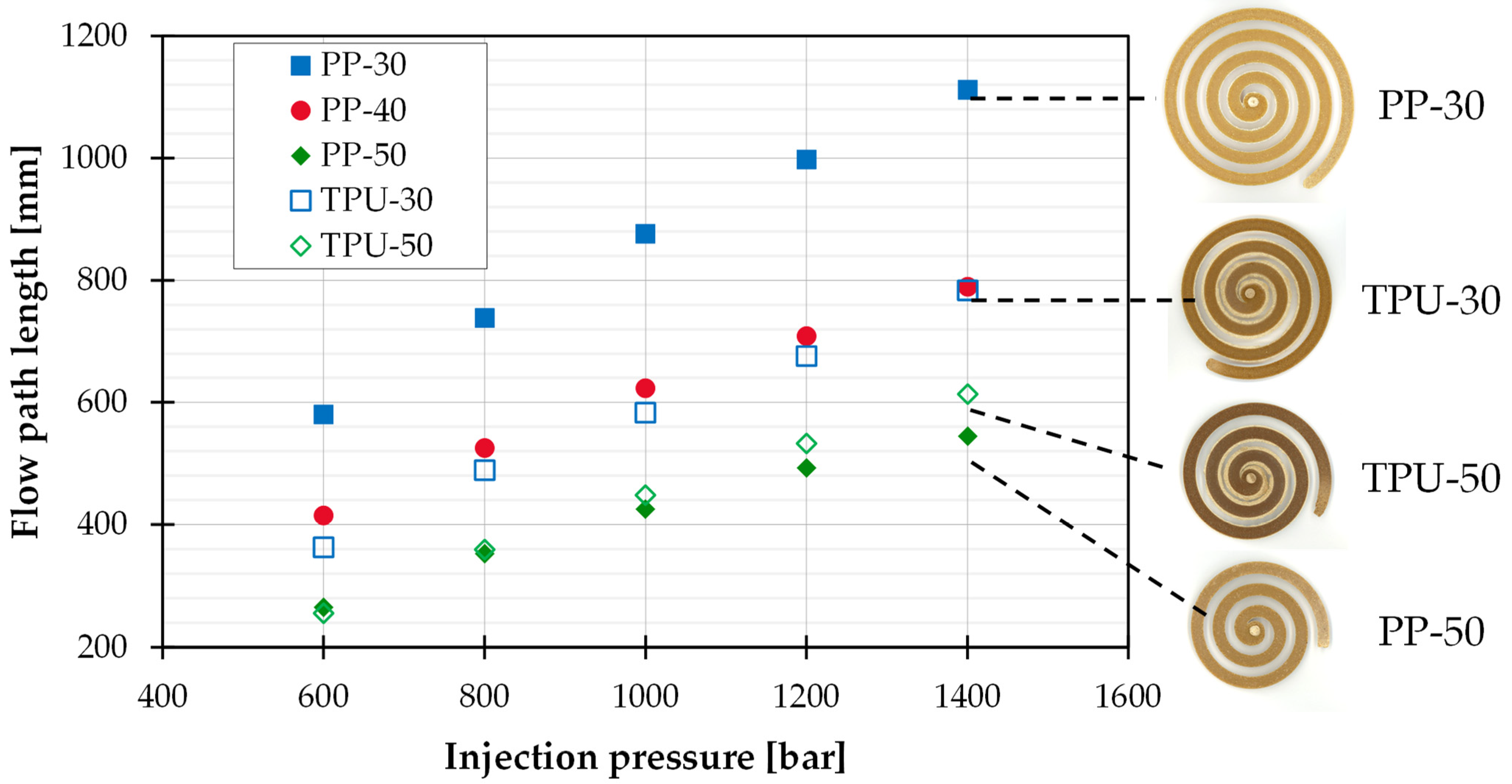
3.1. Flowability

In order to analyze the flow and filling behavior of the listed WPC formulations, two different cavities were selected for the injection molding tests. The flow spiral is used to evaluate the flowability of a plastic melt and, due to its narrow flow channel, has only limited geometric freedom for melt propagation. Figure 1 shows the results of the investigations on the flow spiral.
The flow path length achieved is plotted against the set injection pressure. There is a linear relationship between these two variables, whichever WPC formulation is applied. As the wood content increases, the achievable flow path length also decreases proportionally. Although for a wood content of 50 wt.%, the flowability of TPU and PP are very similar, at a lower wood content of 30 wt.%, the TPU achieves significantly smaller flow path lengths. This may be related to their shear rate-dependent viscosity behavior. While the consistency factors K are significantly higher for the PP-based compounds investigated than for TPU, slopes (1 − n) are much larger, or the flow exponents n are smaller (see Table 3). This means that the viscosity curves of the same wood content and different matrix materials form a common intersection point (see Figure 2).
The intersection point is at approx. 170 1/s for 50 wt.% wood and 350 1/s for 30 wt.% wood. Lower shear rates result in comparatively higher viscosities of the PP and higher shear rates in higher viscosities of the TPU. Since in flow tests, the injection process is pressure controlled, different injection velocities or shear rates in the cavity result for the same set pressure. With increasing wood content, the accompanying increase in viscosity results in correspondingly lower shear rates, which obviously lie before the intersection of the viscosity curves at 30% wood. Another explanation is the slightly more pronounced free jet formation in the TPU with 50 wt.% wood, which increases the total flow path length due to an upstream uncompacted region. Another unexpected deviation when using TPU as matrix material can be seen at a wood fiber content of 40 Ma.%. Here, lower flow path lengths are achieved than with 50 wt.% wood. A methodological error can be ruled out since this behavior occurs with all parameter combinations. In addition to the wood content, the melt and mold temperatures were varied. At higher temperatures, longer flow paths are achieved, with the mass temperature having a significant influence and the mold temperature having only a marginal influence. In all the flow spirals produced, a brittle and non-compacted area can be seen at the end of the flow path, which indicates a local accumulation of wood particles.

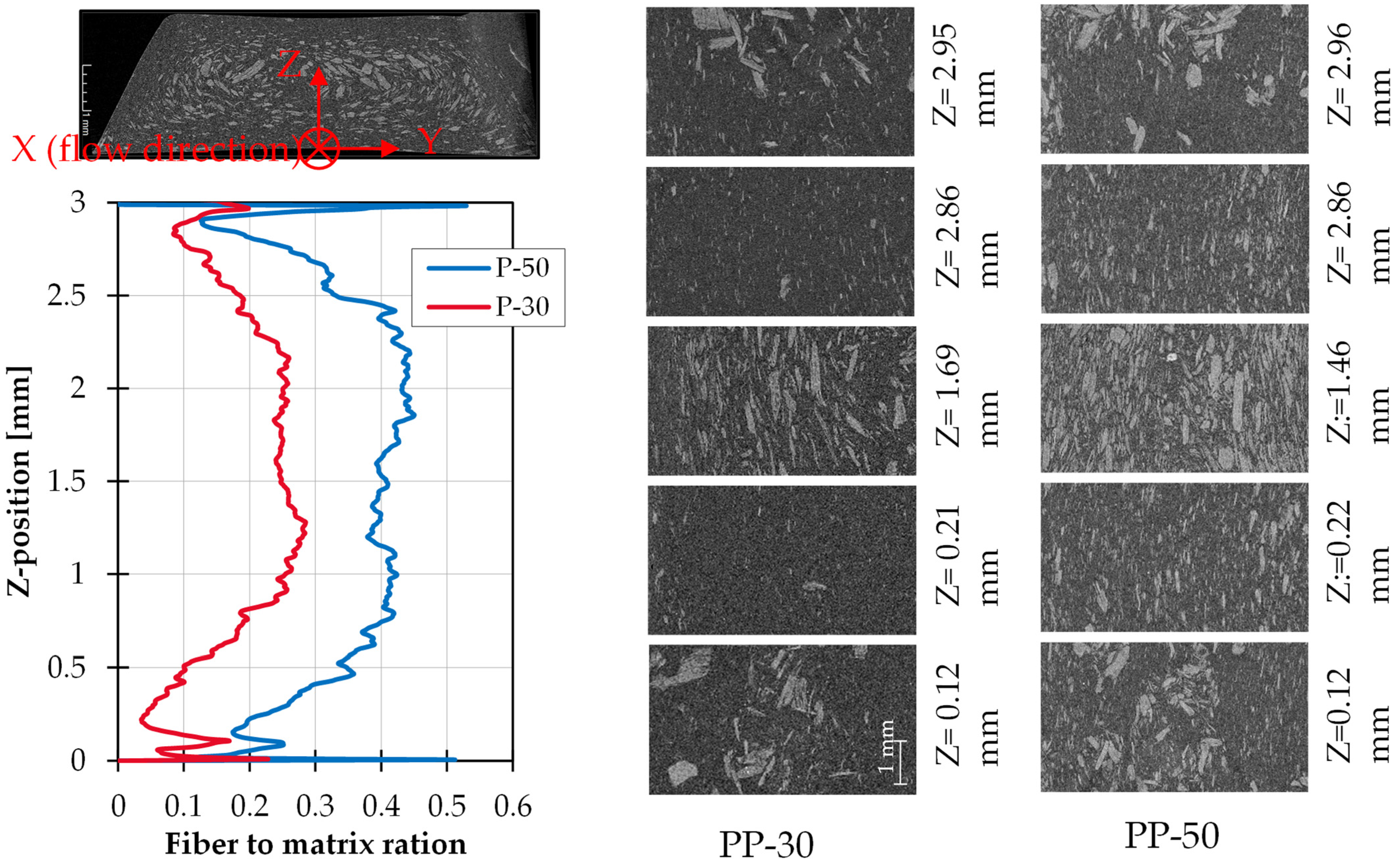
3.2. Filling Behavior

In order to be able to evaluate the filling behavior of real components, filling studies were carried out on a plate mold with higher geometrical freedom with regard to melt propagation. The selected sheet geometry is infiltrated in a semicircular shape by means of swelling flow when using ordinary thermoplastics. Figure 3 shows from left to right the successively increased injection volume of 20, 60 and 100% of the plate cavity for TPU and PP with 30 and 50 wt.% wood. An approximate swelling flow (semicircular melt spread) can be observed for 30 wt.% wood and PP, although with the same wood content but TPU as the matrix material, the flow front already does not form a perfect semicircle. Increasing the wood content to 50 wt.% leads to pronounced flow anomalies for both matrix materials. Melt jets break out of the flow front at the beginning of the injection process. After these reach the opposite mold wall and thus a counterpressure is generated, material flowing downstream flows around the already cooled melt jet in a swelling flow-like manner and forms mechanical weak points in the form of weld lines. TPU at 50 wt.% exhibits more critical behavior than PP. Here, more melt jets emerge from the flow front, and the material flowing downstream also exhibits a more inhomogeneous flow front. When looking at the filling patterns at 60% injection volume, different dark areas can be seen. These are a dark, compacted zone near the gate and lighter, non-compacted areas along the flow front. This phenomenon can be recognized with both matrix materials and a wood content of 50 wt.% and visually indicates different wood contents along the flow path.

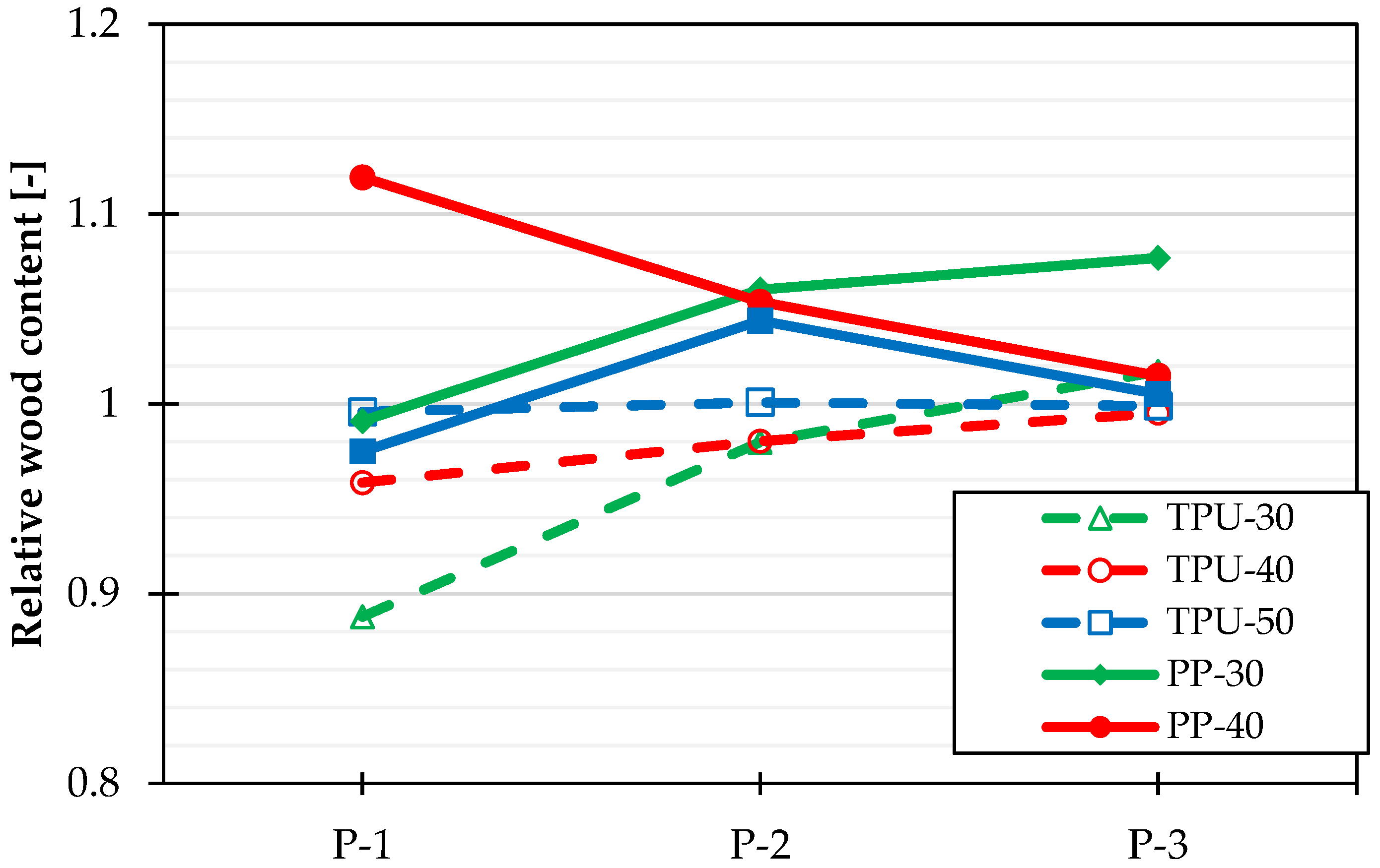
3.3. Determination of the Wood Content

The local wood contents were determined by Soxhlet extraction. Figure 4 and Figure 5 show the results for the flow spiral presented in different ways. Figure 4 shows the absolute wood content over the absolute flow path length at a melt temperature of 190 °C and a die temperature of 60 °C. The different lines (solid = PP, dashed = TPU) and colors (blue = 30 wt.%, red = 40 wt.%, green = 50 wt.%) define matrix material and wood content. At the beginning of the flow spiral, all the materials investigated have a wood content that is only one to two percentage points lower than the respective compounds in [16]. Immediately thereafter, the wood content increases continuously and reaches different final values. For pure PP, an increase in the wood content of about 20% relative to the original value can be observed, irrespective of the initial wood content and the absolute flow path length (see Figure 5). The TPU-based WPC formulations achieve shorter flow paths than the PP-based blends, except at 50 wt.% wood, with a steeper increase in the course of the wood content, thus achieving higher wood contents than PP. Different degrees of percentage increases in wood content at the flow path end exist depending on the wood content. At a wood content of 30 wt.%, the largest segregation was observed, with a wood content increase of 60%. Consequently, the results are consistent with [16,17], although no cyclic alternating pattern of wood fiber content was observed.
For comparison, flow spirals were made with a glass fiber reinforced PP containing 40 wt.% fibers. Contrary to the assumptions in [23], the fiber contents determined after ashing do not show any variation along the flow path within the standard deviation. Glass fibers have a much more uniform geometry because they are not a natural product like wood fibers and therefore show different behavior.
To take a closer look at the cause of wood fiber and matrix material segregation, CT images of the flow spirals were taken. Figure 6 shows images of the beginning of the flow path of the PP-30 and PP-50 spirals with medium process settings. Different Z-positions orthogonal to the flow direction allow a conclusion on layers with different appearances. On the left side of Figure 6, the fiber-to-matrix volume ratio versus the Z coordinate is plotted. In the CT images of both PP-30 and PP-50, it can be observed that the melt flow can be divided into five characteristic layers. At the edges close to the surface, large fibers accumulate in proportion to part agglomerates, with fewer particles present overall (Z = 0.12 mm, Z = 2.95 mm). This is followed by a sliding layer in which hardly any large fibers can be detected. This low-fiber edge layer is very narrow, and subsequently, the volumetric wood content increases successively up to the sample center, where the wood concentration is highest. This is followed by the sliding plane and the edge layer, resulting in a symmetrical scheme. The fibers present in the core have a relatively slimmer shape (higher aspect ratio). The characteristics of the zones are more pronounced for the PP-50 than for the PP-30. The fibers are basically oriented in the flow direction, with a slight deviation in the upper and lower edge areas. Table 4 shows the layer heights determined from the CT images. The edge areas could indicate a possible particle-depleted layer, which contains larger fibers and, according to the findings of Jesinghausen [15], is typical for suspension flows. Similar findings were found for the TPU test specimens (30 wt.%|50 wt.%).
The larger fibers with a lower aspect ratio could experience higher flow resistance than elongated wood fibers during injection due to the larger surface areas in the flow direction, resulting in a lower flow velocity. Accordingly, faster-flowing wood fibers could displace the slower fibers towards the mold wall. Furthermore, the edge layers could also indicate the occurrence of wall sliding during flow. The subsequent flow would accordingly slide on the sliding layer so that the fibers migrate orthogonally to the flow direction into the channel center. The subsequent transition regions, which are characterized by the accumulation of smaller fibers, could also occur as a result of flow velocity differences. The larger, elongated fibers could reach a greater velocity than smaller fibers due to a greater shear rate, resulting in the displacement of the smaller fibers into the transition regions. Due to fiber–fiber interactions, there is basically the possibility that smaller fibers adhere to larger fibers and can thus also be found in the channel center.
Figure 7 shows the relative wood contents for the plate geometry as a function of the removal position. P-1 is located at the beginning of the flow path in the already compacted area. P-2 is in the transition between compacted and uncompacted areas, and P-3 is directly at the uncompacted flow front. In general, due to the significantly shorter flow paths of a maximum of 70 mm, lower deviations of the wood content of 12% can be observed. For PP as the matrix material, no clear tendencies are apparent since, at a wood content of 30 wt.%, the wood content increases in the flow path direction and decreases at 40 wt.%. In the case of TPU as a matrix material, a greater reduction in the wood content can be seen with decreasing initial wood content at the beginning of the flow path, which in turn tends towards the flow front at all wood contents towards the level of the starting material. If the wood content of the WPC formulation is increased further, the wood content at the beginning of the flow path approaches the initial content more closely. Due to the low segregation phenomena measured in the plate geometry and the simultaneous occurrence of melt jets, their cause cannot be conclusively explained by locally increased wood content or partial wall sliding of the wood particles adjacent to the mold edge. Consequently, it cannot be said that the melt jet is due only to local segregation between wood fibers and matrix material. Further investigation needs to be performed regarding different WPC formulations and the exact causes of their flow anomalies.

4. Conclusions

In this publication, the flow, filling and segregation behavior of WPC with different matrices was investigated. A particular focus was on the segregation of the fiber and matrix and determining the fiber content as a function of the flow path length. It was found that PP-based WPC can achieve a significantly higher flow path length than TPU-based WPC with the same fiber content (30 wt.%). This can be explained by the shear viscous flow behavior discussed in Section 3.1. For more densely filled WPC, the flow path length is in the same range, but TPU-based WPC is found to flow slightly further at higher pressures because of free jet formation.
In order to evaluate the filling behavior, filling studies were performed using a plate geometry. For 30 wt.% PP, filling behavior corresponding to swelling flow could be demonstrated. The 30 wt.% TPU showed an approximate swelling flow. With increasing fiber content, there is a deviation from the swelling flow, accompanied by a clearly frayed flow front.
The wood content along the flow path length of a flow spiral was determined by Soxhlet extraction. At the beginning of the flow spiral, only a slight deviation from the initial fiber content of the formulations was detectable, while in the course of the flow path length, a significant increase in fiber content was found. A comparison with glass fiber-reinforced PP showed once more that segregation is a WPC-specific phenomenon. The series of investigations were concluded with CT images, which showed that five layers form within the melt flow of WPC (see Section 3.2). This symmetric five-layer model includes:
  • Edge layer, where large fibers accumulate.
  • Narrow sliding layer with low fiber content.
  • Core layer with high fiber content.
  • Narrow sliding layer.
  • Edge layer.
Based on this publication, it was possible to investigate the filling/flowing and segregation behavior as a function of the different matrix materials and provides starting points for further research efforts to elucidate and develop the five-layer model.

Author Contributions

Conceptualization, M.R. and F.F.; investigation, M.N.; writing—original draft, M.R. and F.F.; supervision, E.M. All authors have read and agreed to the published version of the manuscript.

Funding

This research was funded by the federal state of North Rhine Westphalia, Germany, via the Forschungskolleg “Leicht-Effizient-Mobil” (LEM) and by the Federal Ministry of Economics and Climate Protection on the basis of a resolution of the German Bundestag within the framework of Industrial Collective Research (IGF no. 20365 N).

Conflicts of Interest

The authors declare no conflict of interest.

References

  1. Friedrich, D. Angewandte Bauphysik und Werkstoffkunde Naturfaserverstärkter Kunststoffe: Eine Anleitung für Studium und Praxis; Springer Vieweg: Wiesbaden, Heidelberg, 2021; ISBN 9783658309374. [Google Scholar]
  2. Klyosov, A.A. Wood-Plastic Composites; Wiley: Hoboken, NJ, USA, 2007; ISBN 978-0-470-14891-4. [Google Scholar]
  3. Handbook of Wood Chemistry and Wood Composites; Rowell, R.M. (Ed.) CRC Press: Boca Raton, FL, USA, 2005; ISBN 0849315883. [Google Scholar]
  4. Functional Fillers for Plastics; Xanthos, M. (Ed.) Wiley-VCH: Weinheim, Germany, 2005; ISBN 9783527310548. [Google Scholar]
  5. Vogt, D.; Karus, M.; Ortmann, S.; Schmidt, C.; Gahle, C. Wood-Plastic-Composites (WPC)—Holz-Kunststoff-Verbundwerkstoffe: Märkte in Nordamerika, Japan und Europa mit Schwerpunkt auf Deutschland Technische Eigenschaften–Anwendungsgebiete Preise–Märkte–Akteure; Nova Institut GmbH: Hürth, Germany, 2006. [Google Scholar]
  6. Zion Market Research. Wood Plastic Composites Market-Global Industry Analysis: Wood Plastic Composites Market-By Product (Hospitals & Clinics, Polypropylene, and Polyvinyl chloride), By Application (Building & Construction, Electrical, and Automotive), And By Region- Global Industry Perspective, Comprehensive Analysis, and Forecast, 2021–2028. 2020. Available online: https://www.zionmarketresearch.com/report/wood-plastic-composites-market (accessed on 16 August 2022).
  7. Fachagentur Nachwachsende Rohstoffe e. V. Bioverbundwerkstoffe-Naturfaserverstärkte Kunststoffe (NFK) und Holz-Polymer-Werkstoffe (WPC) 2015. Available online: http://www.fnr.de/fileadmin/allgemein/pdf/broschueren/Broschuere_Bioverbundwerkstoffe-web-V01.pdf (accessed on 18 October 2022).
  8. Steidl, E.; Sobczak, L.; Pretschuh, C. Monitoring of Injection Molding Tool Corrosion and Effects of Wood Plastic Compound’s Moisture on Material Properties. Int. Polym. Process. 2018, 33, 66–75. [Google Scholar] [CrossRef]
  9. Funke, C.; Albring, E.; Moritzer, E. Kunststoffe WPC füllt anders. Kunststoffe 2010, 100, 71–74. [Google Scholar]
  10. Thienel, P.; Hoster, B.; Schröder, T.; Schröder, K.; Kretzschner, J. Duroplastspritzgießen mit Gasinnendruck. Kunststoffe 1993, 83, 91–95. [Google Scholar]
  11. Castro, J.M.; Macosko, C.W.; Tackett, L.P.; Steinele, E.C.; Critchfield, F.E. Reaction injection molding: Filling of a rectagular mold. J. Elastomers Plast. 1980, 12, 3–17. [Google Scholar] [CrossRef]
  12. Michaeli, W.; Hunold, D.; Kloubert, T. Formfüllung beim Spritzgießen von Duroplasten. Plastverarbeiter 1992, 43, 42–46. [Google Scholar]
  13. Duretek, I.; Lucyshyn, T.; Holzer, C. Filling behaviour of wood plastic composites. J. Phys. Conf. Ser. 2017, 790, 12006. [Google Scholar] [CrossRef]
  14. Schröder, C. Verfahrenstechnische Entwicklung zum Hinterspritzen von Echtholzfurnieren mit Wood-Plastic-Composites (WPC); Shaker: Aachen, Deutschland, 2013; ISBN 978-3-8440-2186-8. [Google Scholar]
  15. Jesinghausen, S. Rheo-PIV Nichtkolloidaler Suspensionen: Strukturelle Untersuchungen der Strömungsentwicklung in Schlitzdüsen mit Fokus auf Wandgleiten; Shaker: Aachen, Deutschland, 2017; ISBN 978-3-8440-5600-6. [Google Scholar]
  16. Ramzy, A.Y.; El-Sabbagh, A.M.M.; Steuernagel, L.; Ziegmann, G.; Meiners, D. Rheology of Natural Fibers Thermoplastic Compounds: Flow Length and Fiber Distribution. J. Appl. Polym. Sci. 2014, 131, 39861. [Google Scholar] [CrossRef]
  17. El-Sabbagh, A.; Ramzy, A.Y.; Steuernagel, L.; Meiners, D. Flowability and fiber content homogeneity of natural fiber polypropylene composites in injection molding. In Proceedings of the Regional Conference Graz 2015, Polymer Processing Society PPS: Conference Papers, Graz, Austria, 21–25 September 2015. [Google Scholar]
  18. Nikooharf, M.H.; Rezaei-Khamseh, M.; Shirinbayan, M.; Fitoussi, J.; Tcharkhtchi, A. Comparison of the physicochemical, rheological, and mechanical properties of core and surface of polypropylene composite (GF50-PP) plate fabricated by thermocompression process. Polym. Compos. 2021, 42, 3293–3306. [Google Scholar] [CrossRef]
  19. Moritzer, E.; Richters, M. Characterization of wood-filled thermoplastic polyurethanes for the injection molding process. J. Appl. Polym. Sci. 2021, 138, 50968. [Google Scholar] [CrossRef]
  20. Moritzer, E.; Richters, M. Injection Molding of Wood-Filled Thermoplastic Polyurethane. J. Compos. Sci. 2021, 5, 316. [Google Scholar] [CrossRef]
  21. Moritzer, E.; Flachmann, F. Influence of Chemical Blowing Agents on the Filling Behavior of Wood-Plastic-Composite Melts. In SPE ANTEC 2021: The Annual Technical Conference for Plastic Professionals; Society of Plastics Engineers (SPE), Ed.; Curran Associates, Inc.: New York, NY, USA, 2021; pp. 536–540. [Google Scholar]
  22. Moritzer, E.; Flachmann, F. Process-reliable Injection Molding of Highly Filled Wood-Plastic-Composites (WPC). In Proceedings of the 36th International Conference of the Polymer Processing Society, Montreal, QC, Canada, 26–30 September 2021. [Google Scholar]
  23. Hegler, R.P.; Mennig, G. Phase separation effects in processing of glass-bead- and glass-fiber-filled thermoplastics by injection molding. Polym. Eng. Sci. 1985, 25, 395–405. [Google Scholar] [CrossRef]
Figure 1. Achievable flow path length over the injection pressure as a function of the matrix material (PP, TPU) and the wood content (30, 40, 50 wt.%), as well as scans of the flow spirals at 140 bar injection pressure.
Jcs 06 00321 g001
Figure 2. Viscosity as a function of shear rate at 190 °C for 30 wt.%/50 wt.% PP and 30 wt.%/50 wt.% TPU.
Jcs 06 00321 g002
Figure 3. Filling studies (20, 60, 100% injection volume) depending on the matrix material (TPU, PP) and the wood content (30, 50 wt.%).
Jcs 06 00321 g003
Figure 4. Absolute wood content over absolute flow path length as a function of matrix material (TPU, PP) and wood content (30, 40, 50 wt.%) at a melt temperature of 190 °C and a mold temperature of 60 °C.
Jcs 06 00321 g004
Figure 5. Relative wood content over relative flow path length as a function of matrix material (TPU, PP) and wood content (30, 40, 50 wt.%) at a melt temperature of 190 °C and a mold temperature of 60 °C.
Jcs 06 00321 g005
Figure 6. CT images and the course of the fiber-matrix volume ratio in the height direction of the flow spiral as a function of the wood content at the beginning of the flow path.
Jcs 06 00321 g006
Figure 7. Relative wood content over the removal position of the sheet geometry as a function of the matrix material (TPU, PP) and the wood content (30, 40, 50 wt.%) at a melt temperature of 190 °C and a mold temperature of 60 °C.
Jcs 06 00321 g007
Table 1. Injection molding parameters used.
ParameterFlow SpiralPlate
PPTPUPPTPU
Nozzle temperature T N [°C]180, 190,200190, 200, 210190
Mold temperature T M [°C]40, 60, 8060
Injection pressure p I n [bar]600, 800, 1000, 1200, 14001200
Injection volume flow V ˙ [cm3/s]78 = max.50
Injection volume V [cm3]variable17, 34, 51, 68, 85
Fiber mass content φ [wt-%]30, 40, 50
Table 2. Properties of fiber material investigated.
PropertyArbocel C320Arbocel C400
ColorBeigeBeige
Particle Size200–500 μm200–600 μm
PH-Value (10-% suspension)4.5–6.54.5–6.5
Bulk density160–240 g/L150–250 g/L
Table 3. Model parameters consistency factor K and flow exponent n from regression of viscosity curve using power approach.
Model ParametersPP-30PP-50TPU-30TPU-50
K603527,1204183226
N0.3580.1950.8130.628
Table 4. Heights of the five flow layers determined from CT.
Zone 1Zone 2Zone 3Zone 4Zone 5
PP-30height [mm]0.1060.7951.2670.6630.20
PP-50height [mm]0.100.7061.6270.4810.075
Publisher’s Note: MDPI stays neutral with regard to jurisdictional claims in published maps and institutional affiliations.

