Article

FRP Stay-in-Place Formworks for High Performance of Concrete Slabs

1
Department of Civil Engineering, Thapar Institute of Engineering and Technology, Patiala 147004, India
2
School of Civil and Mechanical Engineering, Curtin University, Bentley, WA 6102, Australia
*
Author to whom correspondence should be addressed.
J. Compos. Sci. 2022, 6(10), 313; https://doi.org/10.3390/jcs6100313
Submission received: 5 September 2022 / Revised: 30 September 2022 / Accepted: 8 October 2022 / Published: 14 October 2022
(This article belongs to the Section Composites Applications)

Abstract

:
Stay-in-Place (SiP) formworks obviate the transportation, placement, removal and storage requirements of conventional formworks. Fibre Reinforced Polymer SiPs (FRP-SiP) have additional advantages, such as corrosion resistance, high specific strength and durability. This paper discusses an experimental instigation consisting of two sets of slabs having varying span-to-depth ratios cast on an FRP-SiP. Control specimens with conventional steel bar reinforcements were also cast. Several treatments for improving interfacial bonds at the interface between concrete and FRP-SiP have been investigated. Cyclic flexural tests were performed to evaluate their structural performance. Load-displacement relationship and load capacity are presented. Failure envelopes and energy absorption capacity were evaluated. It was found that the load capacity of FRP-SiP was around 107% greater than the conventional steel rebar specimens. Bond treatment on the FRP-SiP specimens increased the load capacity by around 215% over the untreated specimens. The load-deflection behaviour and the failure modes of the FRP-SiP specimens were distinctly different from those of the conventional specimens. The flexure and shear provisions in American Concrete Institute Standards (ACI 440) were found to be conservative in comparison to the present results. This study demonstrates that FRP-SiPs improve both the structural performance and construction efficiency of concrete slabs, however, new standards would be necessary to be able to utilize their improved capacity.

1. Introduction

SiP formwork is a permanent participating system that is structurally integrated with concrete. It acts as formwork during construction and doubles up as tensile reinforcement during the service life of the structure. Thus, it eliminates the transportation, assembly, removal, and storage required by conventional formworks. It also obviates the use of steel rebars as reinforcement eliminating bending and placement of the bars. FRP has been used in concrete for both structural retrofits and new construction [1,2,3]. Due to their resistance to degradation, FRP-SiP offers a durable and corrosion-resistant system. It has been demonstrated in prior research that the use of FRP-SiP formwork can leverage the advantage of both FRP in tension and concrete in compression [4,5,6]. FRP-SiP bridge decks are found to be durable in saline environments [7] and freeze–thaw cycles [8].
American Concrete Institute (ACI) Committee 440-J has provided a summary of FRP-SiP for concrete bridge decks that highlights significant research efforts and field applications [9]. FRP-SiP is designed to be stiff enough to withstand the weight of concrete at the time of pouring and strong enough to offer resistance to the tensile stresses developed during the service life of the slab. To develop adequate stiffness, the FRP plate is provided with stiffeners of different forms. Common among them are plates with integrated rib stiffeners [10], T stiffeners [11,12,13], hollow box stiffeners [14,15] and bonded FRP grids [16,17]. Corrugated FRP plates have also been used [18]. The forms are laterally spliced together using either adhesive bonding or mechanical methods [19,20,21].
For the FRP-SiP to be effective as tensile reinforcement, a shear bond between the FRP-SiP and concrete must be ensured. Researchers have reported three different bonding techniques: (1) mechanical bonding, (2) adhesive bonding and (3) aggregate bonding. In the case of mechanical bonding, the stiffeners are pierced to introduce cross members that mechanically bond with concrete. The interface bonding techniques do not need the cross members, and thus, avoid the weakening of the stiffeners. He et al. [22] observed that interface bonding performed better than cross bars. In the case of an adhesive bonded interface, the concrete-facing surface of the FRP formwork is coated with a layer of adhesive. The bonding is achieved by pouring concrete over the formwork within the pot life period of the adhesive. Different researchers have reported an increase of the load carrying capacity of decks with adhesively bonded specimens over untreated ones, ranging from 0 to 105% [12,18,19,20]. The commercially available adhesives that are used in these investigations are for application on cured concrete, while in the case of adhesive bonding, wet concrete is poured over the adhesive. Evidently, selection of the adhesive and the quality of its application in the field have a great impact on the capacity and failure mode of the composite. In the case of aggregate bonding, a layer of fine aggregates is adhesively bonded on the FRP-SiP surface. Concrete is then poured over the bonded aggregates. Thus, this method depends on the mechanical bonding between the concrete and the formwork. It has been reported that bonding using smaller size aggregate with higher distribution density gives better shear bonding and results in a higher initial cracking moment and ultimate capacity in comparison to untreated ones [11,23]. From the above discussion, it is clear that an interfacial bond treatment is beneficial for FRP-SiP. However, there is no clear favorite between adhesive bonding and aggregate bonding. In our coupon tests, we found that adhesive bonding is more convenient to use and performs marginally better in comparison to aggregate bonding [24,25]. It was also noted that bond treatment with the proper choice of adhesive could move the failure location from the interface into the concrete [26].
Despite the promising performance of the FRP-SiP concrete hybrid system, its adoption remains limited due to several open problems. The lack of ductility and resulting explosive failure is considered a concern for FRP-SiP. Gai et al. [27] proposed a system with an FRP box section on the tensile side and an FRP grating on the compression side interconnected with FRP dowels as shear studs to improve the ductility of the slab. Admittedly, a simpler method of construction would be desirable. Cyclic load tests of a simple plate-stiffener type FRP-SiP have found that the fatigue degradation of these slabs can be improved by careful selection of FRP and concrete combination [28,29]. Lastly, the present codes for FRP–concrete systems do not cover design with FRP-SiP. Simple design procedures would also be required for wider application of the technology [30,31].
So far, FRP-SiP technology has been developed with a view to be used as bridge decks. There is a huge potential application of FRP-SiP for a wide range of structures, for example, roof slabs and culverts. For this purpose, however, the performance of FRP-SiP vis-à-vis the standard steel bar reinforced concrete slabs must be investigated, both in terms of strength and failure behaviour. Construction with FRP-SiP system must be simpler than the present method of construction. A simple method of estimating the capacity of FRP-SiP slabs is necessary. This paper explores a generic application of FRP-SiP for concrete slabs. Experimental investigations on the behaviour of one-way concrete slabs cast on FRP-SiP have been reported. Two sets of slabs have been tested with different span to depth ratios, one being flexure critical and the other being shear critical. The slabs were subjected to a four-point cyclic loading test to study their load capacities as well as their post-yield performance. The following new knowledge has been presented: (a) performance of FRP-SiP vis-a-vis standard steel bar reinforced slabs; (b) a new method of assessment of post-yield behavior through energy dissipation; and (c) a comparison of different bond treatments. Based on the experimental results, an estimate of the load capacity of the slabs is presented. The results would be useful in the design of a general-purpose FRP-SiP.

2. Materials and Methods

2.1. Test Specimens and Parameters

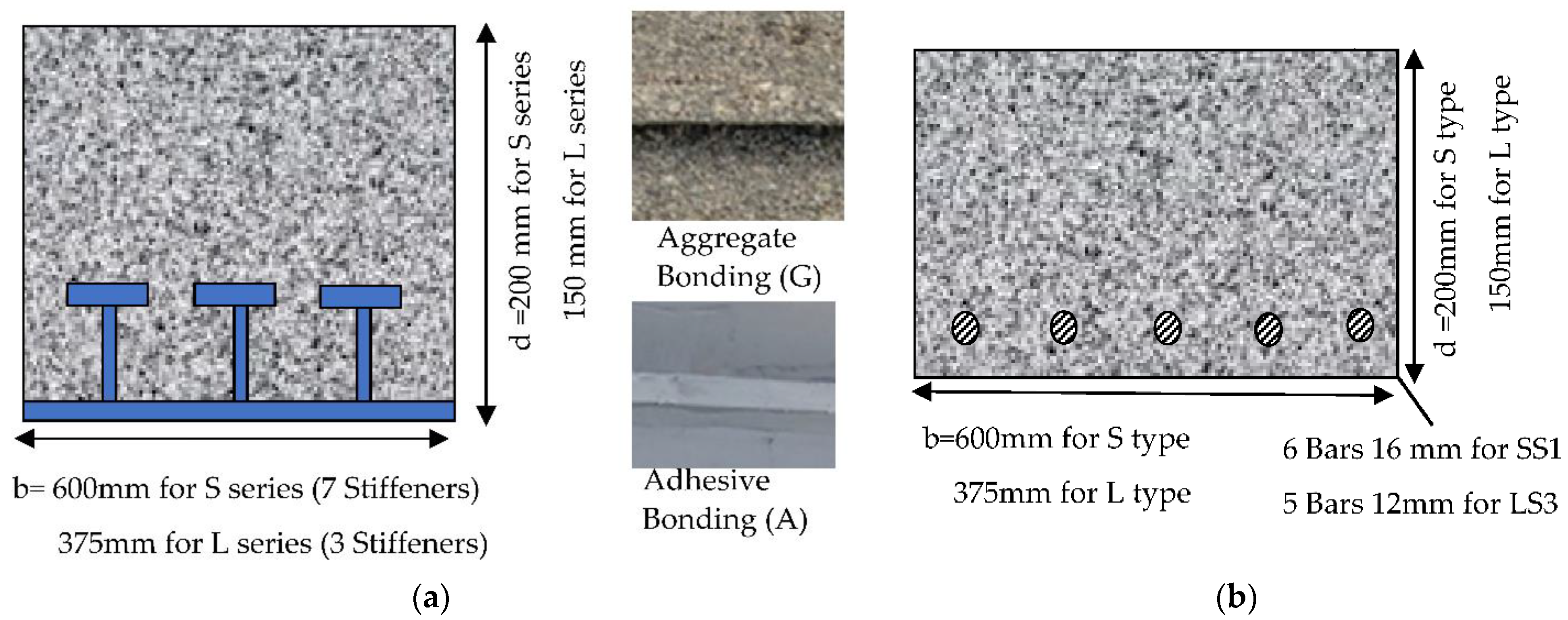
Flexural tests were performed on specimens prepared by using FRP-SiP formwork. The details are provided in Table 1. Two sets of one-way slabs of dimensions 3200 mm × 380 mm × 150 mm and 1100 mm × 600 mm × 200 mm were cast. Each set had four slabs, out of which, three were prepared using FRP-SiP formwork and one with conventional steel reinforcement (S). In the slabs using FRP-SiP formwork, no other tensile or shear reinforcement was used. The slabs had three types of interfaces: control specimen with no bond treatment (C), adhesive bonding (A) and aggregate bonding (G). Self-compacting concrete of characteristic strength 50 MPa was used. The span-to-depth (a/d) ratio of 1 m span slab series was 5, which was relatively small. Therefore, these specimens were shear bond critical. These specimens are named as S series. Whereas the (a/d) of 3 m span slab series was 20, making it flexural-bond critical. These specimens are named as L series. Conventional steel reinforced specimen (SS1) was designed as a standard culvert as used presently. It had no shear reinforcement and it was cast with conventional removable formwork. It was reinforced with 6 steel bars of 16 mm diameter with a reinforcement ratio of 1.18%. It was a nearly balanced section according to Indian Standards (IS 456). All other specimens were cast on FRP-SiP. SC1 and LC3 served as the control specimens with no interfacial bond treatment. SA1 and LA3 were given adhesive bond treatment, while SG1 and LG3 were given aggregate bonding treatment.

2.2. Materials

Commercially available pultruded GFRP plank with T-shaped ribs was selected as the formwork (Figure 1). The role of the longitudinal T ribs is to provide the formwork enough stiffness so that it can bear the weight of fresh concrete at the time of pouring. The ribs offer mechanical anchorage with cured concrete. Samples from several locations of the plate and the ribs were tested for tensile strength, modulus of elasticity and fibre volume fraction, according to ASTM D3039 and ASTM D 2584. The results are reported in Table 2. It can be seen that the plates had a relatively higher modulus and strength in comparison to that of the ribs. This is due to the relatively higher fraction of fibres in the plate.
All specimens were cast using self-compacting concrete of compressive strength 50 MPa at 28 days. Self-compacting concrete was used to assure the uniform flow of concrete beneath the T-stiffeners without any external vibration in the concrete. The mass ratio of the concrete mix was 1 (cement): 0.45 (water): 1. 5 (fine aggregate): 0.94 (coarse aggregate with a maximum size 10 mm): 0.015 (water-reducing admixture). A sulfonated naphthalene polymers-based admixture was used as the water-reducing admixture. A slump flow diameter of 600 mm was achieved in the workability test. Properties of the bonding adhesive used are described in detail in Table 3. The selected adhesive was used for both adhesive bonding and aggregate bonding. A T50 cm test was conducted to discover the time taken, in seconds, from the instant the cone is lifted to the instant when horizontal flow reaches a diameter of 500 mm. The average T50 was 4 s. The ultimate compressive strength was found to be 50 MPa. The density of the self-compacting concrete was found to be 17.72 kN/m3.

2.3. Preparation of Specimens

Two sets of slabs of span lengths 1 m (S series) and 3 m (L series) were fabricated. Figure 2 presents the schematic diagrams of the specimens along with the surfaces of the formwork after adhesive bonding and aggregate bonding treatments. The FRP formworks were cut to the required size. The surface to be in contact with concrete was cleaned using acetone. Bond treatments were applied on the formworks as planned. Control specimens were cast directly on the formwork without any treatment. LA3 and SA3 specimens were coated with a thin layer of adhesive. Adhesive was applied with the help of steel laminates of thickness 1 mm. Adhesive thickness settled in range of 1–1.5 mm The coating process took around 35 min for the S series specimens and 55 min for the L series specimens. The adhesive was applied only on the horizontal portion of the formwork. Around 1.7 kg of adhesive was used to coat the S series specimens and 2.8 kg was used to coat the L series specimens. Immediately after the adhesive coating was completed, concrete was poured over the plank. The samples with aggregate coating were prepared in two stages. First, the adhesive was applied to the formwork, as in the case of adhesive bonding. Then, a layer of fine aggregate was sprinkled over the adhesive and lightly pressed. The adhesive was cured for 7 days. It was then brushed lightly to remove loose aggregates. Around 1.7 kg adhesive and 1.5 kg aggregates were used for aggregate coating on S series specimens and 2.8 kg adhesive and 2.65 kg aggregates were used for L series specimens. In the LA3 specimen, adhesive coating took around 55 min, which was slightly more than the 45 min pot life of the adhesive. In control specimens SC1 and LC3, concrete was directly cast over them without any bond treatment. In specimen SS1 six steel bars of diameter 16 mm were placed at a distance of 30 mm from the bottom. In specimen LS3 five steel bars of diameter 12 mm were placed at a distance of 25 mm from the bottom. All eight specimens were moist cured for 28 days.

2.4. Experimental Setup

All specimens were tested in a four-point bending setup, as shown in Figure 3. Slab specimens were supported at the ends on 25-mm diameter steel rollers. The center-to-center spacing of supports (represented as L in Figure 3) was 1 m for the S series and 3 m for L series slabs. All S series and L series specimens were tested with a constant moment zone of 0.33 m and 1 m, respectively. Deflections were measured using LVDTs at the centre and the quarter-span of each specimen. Four 5 mm long strain gauges were used to measure strains at the bottom of FRP-SiP specimens as shown in Figure 3 One 60 mm strain gauge was located at the central position on top concrete in each specimen. Each strain gauge was connected to a data acquisition system. The load was applied using a servo-controlled hydraulic jack cyclically up to a specified limit and unloaded to zero. The load cycle was repeated with a specified load increment in each cycle. The S series specimens had a load step of 60 kN, while the L series specimens had a load increment of 30 kN.

3. Results

3.1. Load-Deflection Plot

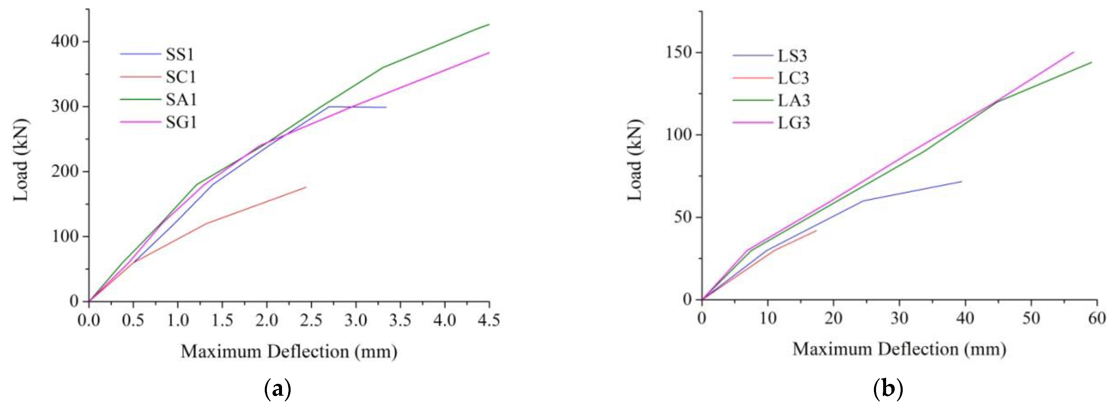
Four-point loading tests were performed on both S series and L series slab specimens. Figure 4 shows the load-deflection plots for the S series slabs and the corresponding image specimens at the end of the test. SS1 (Figure 4a) underwent five full cycles of loading before it failed at around a 300 kN load. It can also be seen that the specimen underwent hysteresis at each cycle of loading; at an average of five full cycles, it was around 1.7 mm. The specimen developed a few cracks in the flexure zone. However, it failed due to a shear crack that developed in the zone between the load and the support. After unloading, a good deal of recovery in the deformation was noticed. SS1 had conventional longitudinal steel reinforcement. The ductility of the steel is exhibited in the recovery. However, the ductile behavior was not dominant in the load-deflection behavior of the slab because it failed in shear.
SC1 (Figure 4b) withstood two cycles of loading with a load capacity of around 170 kN, the hysteresis was 1.2 mm. Two vertical cracks were noticed, corresponding to the load points. No shear crack was visible. However, a horizontal slip was noticed at an early stage of loading, which grew continuously. In this case, the failure was due to the shear slip between the formwork and concrete. A smooth surface of the FRP-SiP was visible after the test. This sample was not given any bond treatment. As a result, there was no composite action between the FRP and the concrete. Thus, the FRP-SiP did not act as tensile reinforcement. Clearly, a bond treatment on FRP is warranted to utilize the formwork as tensile reinforcement. SA1 (Figure 4c) and SG1 (Figure 4d) both withstood seven load cycles. These specimens could withstand around a 400 kN load with a hysteresis of about 2 mm. The load capacity of these specimens was markedly higher than that in both of the control specimens, SS1 and SC1. This result demonstrates the efficacy of FRP-SiP. Both SA1 and SG1 failed similarly. A shear crack developed in the zone between the load and the support. As a result, the concrete was split into two pieces. That created a tied arch mechanism with the FRP-SiP acting like a tie. The tension in the FRP-SiP was transferred to the concrete as interfacial shear. The T stiffeners played an important role in the bonding of the FRP with concrete. When the stiffeners started to delaminate from the plate, the shear crack propagated rapidly along the horizontal plane of the FRP–concrete interface. The larger segment of the slab was 2.5 times longer in length than the shorter piece. Thus, the shear stress on the shorter piece was approximately 2.5 times that on the longer. Ultimately, excessive shear stress caused debonding in the shorter fragment of the specimen. It was noticed that a thin layer of concrete was attached to the FRP surface. Thus, it can be concluded that the applied bond treatment was adequately strong and the failure plane had moved inside the concrete. Clearly, interfacial bonding is the critical factor in the load capacity of short FRP-SiP specimens. Table 4 presents the summary of the results.
Figure 5 shows the load-deflection plots for L series slabs along with the samples at the end of the experiment. These slabs are much more slender than the S series slabs, and they are expected to exhibit flexural behavior. LS3 (Figure 5a) developed numerous vertical cracks during the process of loading. It failed due to the yielding of steel reinforcement followed by the separation of compression concrete under the loading point. It demonstrated the behavior of a typical slab with under-balanced steel reinforcement. The load capacity of the specimen was around 70 kN and had an average hysteresis of 5 mm.
LC3 (Figure 5b) started in the same fashion but developed fewer vertical cracks. The slip at the FRP–concrete interface was noticed very early in the loading cycle. The load capacity of the specimen was rather limited at around 40 kN. As in the case of SC1, the failure plane was at the concrete–FRP interface. This result demonstrates the necessity of bond treatment at the interface to utilize the FRP formwork as tensile reinforcement.
LA3 (Figure 5c) and LG3 (Figure 5d) exhibited marked improvement over LC3 and LS3. They could withstand four full cycles of loading, in comparison to just two cycles in LS3 and one cycle in LC3. The load capacity went up more than three folds over LC3. The maximum deflection of the specimens went up by more than two times. This dramatic difference is due to the bond treatment applied to the FRP-SiP. The load capacity of LA3 and LG3 was more than double that of the LS3, the slab with conventional steel rebar. The deflection at maximum load was 1.6 times more than that of LS3. Clearly, FRP-SiP can surpass the performance of conventional slabs reinforced with steel bars, provided the interfacial bond between concrete and FRP is adequately secured. This experiment demonstrates that FRP-SiP construction is likely to be more economical than conventional steel-reinforced slabs. However, the FRP-SiP specimens failed more suddenly than LS3. This aspect will be analyzed later in this paper.
Both LA1 and LG1 failed in a similar fashion. A diagonal crack developed in the zone between the load and the support. As a result, the concrete was split into two pieces. That created a tied arch mechanism, with the FRP-SiP acting like a tie. The tension in the FRP-SiP was transferred to the concrete as interfacial shear. The T stiffeners played an important role in the bonding of the FRP with concrete. When the stiffeners started to delaminate from the plate, the crack propagated rapidly along the horizontal plane of the FRP–concrete interface. The larger segment of the slab was two times longer in length than the shorter piece. Thus, the shear stress on the shorter piece is approximately two times that on the longer piece. Ultimately, excessive shear stress caused debonding in the shorter fragment of the specimen. It was noticed that a thin layer of concrete was attached to the FRP surface. Thus, it can be concluded that the applied bond treatment was adequately strong and the failure plane had moved inside the concrete. Clearly, interfacial bonding is the critical factor in the load capacity of short FRP-SiP specimens. Although LA3 and LG3 showed very close load-deflection plots, the load capacity of LG3 was marginally higher. The reason behind this phenomenon can be the time taken in the adhesive coating of the FRP-SiP. Pot life of the adhesive was 45 min, but it took 55 min to completely coat the 3 m long formwork. Concrete casting took place slightly after the recommended pot life of the adhesive. In case of aggregate bonding, aggregates were sprinkled readily after the application of the adhesive. Thus, there was no delay.

3.2. Hysteric Properties

The cyclic loading tests performed in this investigation allow us to study the hysteretic properties of the specimens. To perform the hysteretic analysis, envelop curves were derived from the cyclic load-deflection plots. Figure 6 represents the load-deflection envelops for S series samples. They behave almost identically in the initial linear part of the curve. This indicates that the behavior of the slabs under service load conditions is likely to be very similar. SC1 starts to exhibit softening behavior at about 60 kN load. SS1 deviates from the pack at around 300 kN. Softening is initiated in SG1 at around 200 kN but, it continues to withstand additional load until it fails at 400 kN. SA1 withstands the maximum load of 450 kN.
In the case of L series specimens, LS3 and LC3 specimens behaved differently from LA3 and LG3 specimens in the initial linear part of the curve, as in these specimens, flexural cracks appeared comparatively before those in bond treated specimens (Figure 6b). LC3 started to exhibit softening from the initial stages itself, as no composite action was there between the FRP-SiP formwork and the concrete. LS3 exhibited softening at 30 kN. Softening was initiated in both LA3 and LG3 specimens at 30 kN but continued to withstand an additional load up to 150 kN.
The area under the curve of each loading cycle was calculated as:
E i = d i 1 d i 2 Fdx d i 2 d i 3 Fdx
where
  • Ei = Energy absorbed in the ith cycle of loading
  • di1,2,3 = Displacements at the beginning, peak load, and end of ith cycle
  • F = Applied force
The cumulative area has been calculated as:
E c   = i = 1 n E i
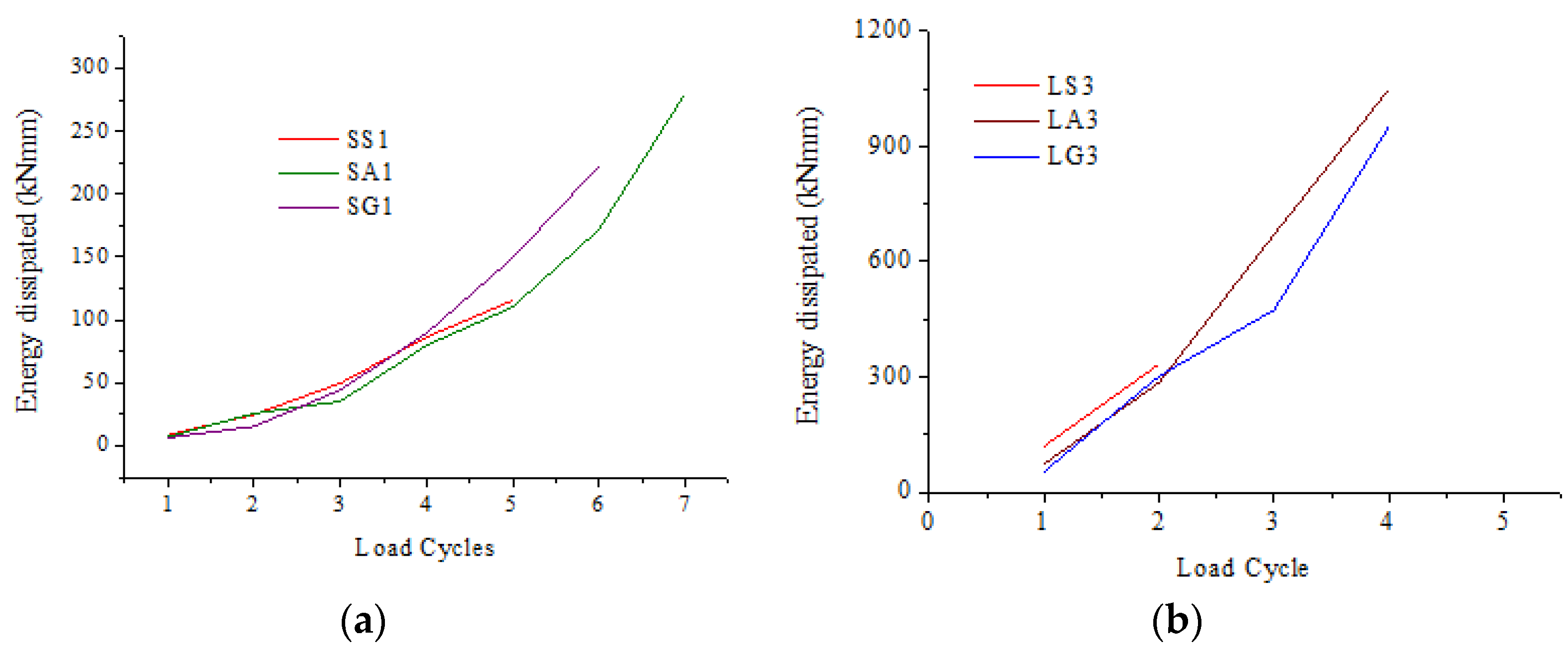
Ei can be considered the energy dissipation norm for the cycle. Figure 7a shows E at different load cycles for S series specimens. Initially, the curves were closely packed. As the cycles advanced, the SA1 and SG1 went higher than SS1. SS1 reached a maximum of 115 kNMm, which was around 50% lower than SG1 (222 kNmm) and SA1 (279 kNmm).
The plot of E with cycles for L series specimens is presented in Figure 7b. In this case, the gap in E between steel rebar specimen LS3 (333 kNmm) and that in FRP-SiP specimens is even larger than that in S series specimens. E for LS3 was just 30% of that of LA3 (1048 kNmm) and LG3 (950 kNmm). Although FRP-SiP is not a ductile material, the composite can absorb substantially large energy in cyclic loading. In fact, the energy norm of FRP-SiP is much higher than that of conventional steel reinforced slabs. The gap becomes larger with the increasing span-to-depth ratio of the slab.
Figure 8 shows cumulative Ec for S and L series specimens. For SS1 type maximum cumulative energy dissipation was 284 kNmm at the end of 5 cycles. For SA1 and SG1 it was more than 500 kNmm. SA1 showed 30% more Ec than SG1. In the case of L series specimens, LS3 had an Ec of 452 kNmm. FRP-SiP specimens surpassed Ec by more than 3 times. The highest cumulative energy dissipation capacity was shown by LA3 (2076 kNmm). LG3 was slightly lower at 1789 kNmm. To analyse the relative performance between LA3 and LG3, more tests will be necessary.

4. Design Methodology

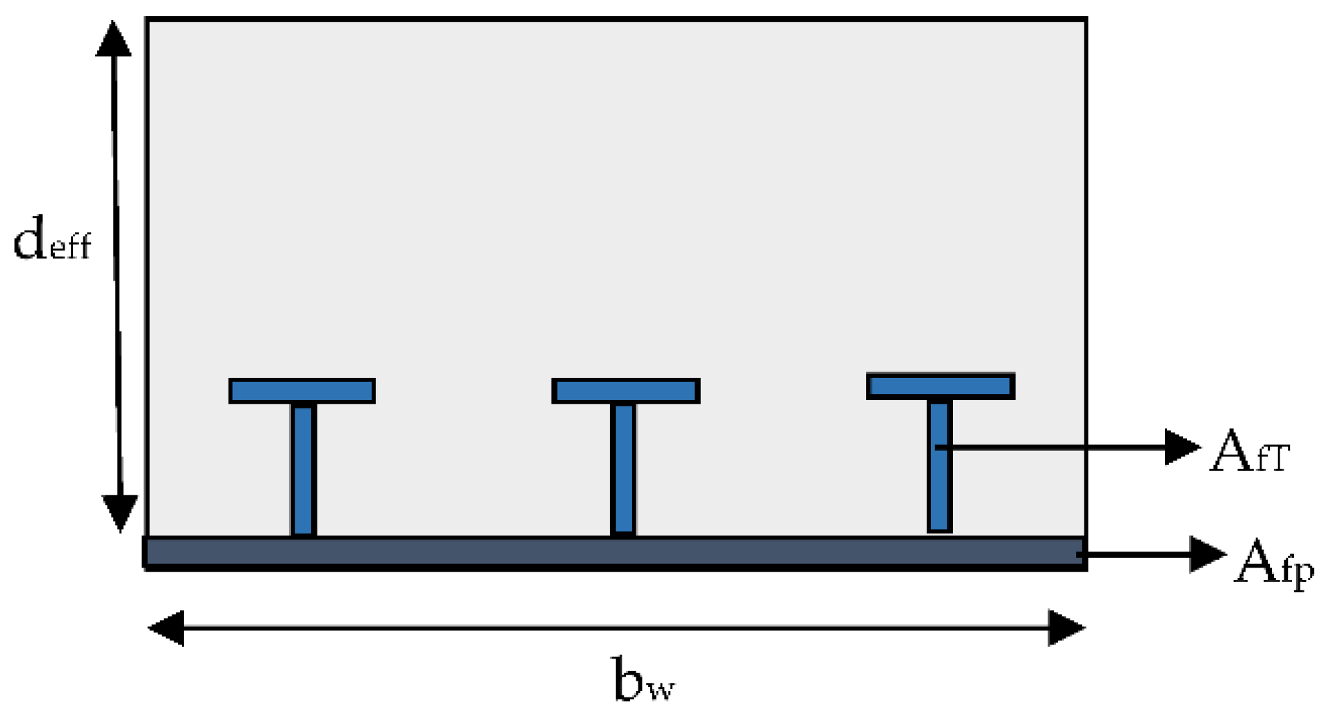
There is no design code for FRP-SiP to the best of the authors’ knowledge. The design code that is widely used for designing concrete structures reinforced with FRP is ACI 440: 2015 [32]. However, this code is for FRP bars. In absence of a better alternative, the results of this experiment have been compared with the provisions ACI440:2015. The same method has been adopted in some other studies [9,22,33,34]. The parameters for the slabs are presented in Figure 9 and their values are in Table 5. The ratio (ke) of the elastic neutral axis depth (ce) to effective reinforcement depth (deff) is given by Equation (3):
k e = c e d eff = ɳ ρ 2 + 2 ɳ ρ -   ɳ ρ
where the FRP reinforcement ratio is ρ and the modular ratio of FRP to concrete is ɳ .
The effective depth (deff) and FRP reinforcement ratio ρ used in Equation (3) is determined from Equations (4) and (5), respectively
d eff = A fp E fp d fp +   A fT E fT d fT A fp E fp +   A fT E fT
ρ = A fp +   A fT bd eff
where Afp, AfT denotes the area of FRP base plate and total area of FRP T-stiffener, respectively. Efp, EfT and dfp, dfT denotes the longitudinal tensile modulus and effective depth of the FRP base plate and FRP T stiffeners, respectively.
The modular ratio ɳ used in the above equation was obtained using an effective FRP modulus Eeff
E eff = A fp . E fp +   A fT E fT A fp +   A fT
Balanced reinforcement ratio is given by the expression:
ρ fb = 0.85 β 1 f c f fu E f ε cu E f ε cu + f fu
β 1 = 0.85 f c 28 MPa 0.85 0.05 f c 28 7 28 MPa < f c 0.65 f c > 55 MPa 55 MPa
where β1 is the Whitney stress block coefficient, f′c is the compressive strength of concrete, ε cu is the ultimate strain in concrete, Ef is the FRP modulus and ffu is the ultimate tensile strength of FRP.
Both S and L series slabs are over-reinforced (Table 5). Thus, the ratio (kover) of the ultimate neutral axis depth (cover) to effective reinforcement depth (deff) is calculated by Equation (8), assuming linear strain distribution along with Whitney stress block.
k over = c over d eff = n ρ m 2 + 2 n ρ m     n ρ m
where
m = E c ε cu 1.7 β 1 f c
The moment capacity for an over-reinforced section is given by the equation:
M n = A fp E fp ε cu d fp c c d fp β 1 c 2 + A ft E ft ε cu d ft c c d ft β 1 c 2
where ε cu is the concrete failure strain at ultimate failure (0.003) and c is neutral axis depth for over-reinforced sections at ultimate failure (cover).
According to Equation (10), load capacity against bending moment for the S series slab is 948 kN and that for the L series slab was 116 kN.
In ACI 440: 2015, the shear strength algorithm for concrete structures without transverse reinforcement is based on the assumption that the resistance to shear force is provided by the uncracked concrete above the neutral axis at the critical shear crack section. The nominal shear strength capacity (in SI units) of concrete is given by the expression
V n = 0.415 k e f c b w d eff
k e = c e d eff = ɳ ρ 2 + 2 ɳ ρ ɳ ρ
where f′c is the compressive strength of concrete, bw is the width, deff is the effective depth, ρ is the FRP reinforcement ratio and ɳ is the modular ratio of section.
In the experiment, it was observed that the FRP remained intact until close to the load capacity of the slab. Thus, the assumption that only concrete in the compression zone resists shear is likely to be over-conservative. Prior research supports this argument [35,36,37,38,39,40,41].
Shear capacity was also calculated based on the ACI 318 (2014) [42] algorithm that recognizes the entire effective depth of concrete instead of the uncracked depth. A similar approach has been adopted in [14,35].
V n = 0.17 f c b w d
where fc is the compressive strength of concrete in MPa, bw is the width of the slab in mm and d is the effective depth of the slab.
The limit capacity is the minimum of estimated flexure and shear capacities. Table 6 presents the experimental and estimated values. The shear capacities based on ACI 440 may not be applicable for FRP-SiP. Similar observations have been made by [43]. Thus, the minimum of the flexure capacity according to ACI440 and shear capacity according to ACI 318 have been presented as limit capacity

5. Concluding Remarks

This paper presents experimental results of full-scale concrete one-way slabs cast on FRP-SiP. Standard T-ribbed glass FRP plates were used as SiP formwork. The FRP-SiP played the role of formwork at the time of casting and that of a tensile reinforcement after curing. Two different bond treatments were used at the FRP–concrete interface. Control specimens with standard steel rebars were also cast. Two sets of slabs were tested with different span-to-effective depth ratios. The slabs were subjected to cyclic loading and their mechanical behavior was observed. The results were compared with the prevailing design codes. The following conclusions were reached in this paper:
  • The present FRP-SiP formwork could serve its dual intended purpose of formwork and tensile reinforcement. The FRP-SiP considerably reduced the number of work steps and eased the construction of the slabs.
  • Bond treatment at the FRP–concrete interface is a critical factor in this type of construction. No gain compared to the standard steel bar reinforced slabs was observed in the case when the interface was left untreated. However, bond-treated FRP-SiP surpassed the performance of the standard slab by a considerable margin.
  • The performances of the adhesive bonding and aggregate bonding were close to one another. From the point of view of ease of construction, wet adhesive bonding is convenient. However, the application of the adhesive on the FRP must take place within the pot life of the adhesive.
  • All of the short slabs (S series) exhibited the typical shear failure. A diagonal crack was observed within one of the shear spans leading to failure. However, in the case of FRP-SiP, the direction of the crack diverted to the concrete–FRP interface, and the FRP ripped off from the concrete. FRP-SiP had 40% more load capacity than the conventional steel reinforced slab.
  • In the case of the long slabs (L series), the steel reinforced slab failed by yielding steel reinforcements, followed by concrete crushing. The failure mode in the bond-treated FRP-SiP remained the same for the S and the L series, with diagonal cracking followed by the ripping off of the FRP from concrete. FRP-SiP had a 107% greater load capacity than the conventional steel reinforced slab.
  • A thin layer of concrete was attached to the FRP along the failure plane. This indicates that the failure was in the concrete.
  • The hysteretic properties of the slabs were estimated from the cyclic load tests. Bond-treated FRP-SiP showed superior energy dissipation capacity than even the steel bar-reinforced specimens.
  • The specimens were analysed using both the ACI Committee 440 recommended flexure and shear design provisions. As ACI 440 considers the shear capacity of the cracked concrete only, the shear capacity was also calculated based on ACI 318 that including the contribution from the FRP. The load capacities obtained experimentally were compared with those from the codes. It was observed that the experimental capacities were considerably higher than those of the codes.
This investigation reveals the huge potential of FRP-SiP in general concrete slab construction. FRP-SiP can offer an economical, reliable and possibly durable alternative to the present technology. However, new design methods must be developed. Use of the present ACI codes, which were developed for conventional FRP bar or laminates lead to a rather conservative estimate. More research is required to develop a design methodology for FRP-SiP construction. The failure of FRP-SiP was sudden. It may be worthwhile to attempt a more graceful failure of the structure. Another concern could be FRP’s susceptibility to fire. The success of the initial phase of research encourages the authors to investigate these factors in the future.

Author Contributions

Conceptualization, R.G. and A.M.; methodology, R.G. and A.M.; validation, R.G., A.M. and S.G.; formal analysis, R.G., A.M. and S.M.; investigation, R.G., A.M. and S.M.; resources, R.G. and S.G.; data curation, R.G. and S.M.; writing—original draft preparation, R.G.; writing—R.G., A.M., S.M. and S.G.; visualization, R.G. and S.M.; supervision, A.M. and S.G.; project administration, R.G.; funding acquisition, R.G. All authors have read and agreed to the published version of the manuscript.

Funding

First Anthor RG got the funding of Research by Department of Science and Technology (DST) Grant number SR/WOS-A/ET-115/2011 dated 23 May 2012.

Data Availability Statement

Not applicable.

Acknowledgments

The first author gratefully acknowledges the financial support provided by the Department of Science and Technology, India under women scientist scheme (WOS-A).

Conflicts of Interest

The authors declare no conflict of interest.

References

  1. Bakis, C.; Bank, L.; Brown, V.; Cosenza, E.; Davalos, J.; Lesko, J.; Machida, A.; Rizkalla, S.; Triantafillou, T. Fiber-Reinforced Polymer Composites for Construction—State-of-the-Art Review. J. Compos. Constr. 2002, 6, 73–87. [Google Scholar] [CrossRef] [Green Version]
  2. Djeddi, F.; Ghernouti, Y.; Abdelaziz, Y.; Alex, L. Strengthening in flexure–shear of RC beams with hybrid FRP systems: Experiments and numerical modeling. J. Reinf. Plast. Compos. 2016, 35, 1642–1660. [Google Scholar] [CrossRef]
  3. Zaman, A.; Gutub, S.A.; Wafa, M.A. A review on FRP composites applications and durability concerns in the construction sector. J. Reinf. Plast. Compos. 2013, 32, 1966–1988. [Google Scholar] [CrossRef]
  4. Hall, J.; Mottram, J. Combined FRP Reinforcement and Permanent Formwork for Concrete Members. J. Compos. Constr. 1998, 2, 78–86. [Google Scholar] [CrossRef]
  5. Alagusundaramoorthy, P.; Harik, I.E.; Choo, C.C. Structural Behavior of FRP Composite Bridge Deck Panels. J. Bridge Eng. 2006, 11, 384–393. [Google Scholar] [CrossRef]
  6. Honickman, H.; Fam, A. Investigating a Structural Form System for Concrete Girders Using Commercially Available GFRP Sheet-Pile Sections. J. Compos. Constr. 2009, 13, 455–465. [Google Scholar] [CrossRef]
  7. Fam, A.; Boles, R.; Robert, M. Durability in a Salt Solution of Pultruded Composite Materials Used in Structural Sections for Bridge Deck Applications. J. Bridge Eng. 2015, 21, 04015032. [Google Scholar] [CrossRef]
  8. Boles, R.; Nelson, M.; Fam, A. Durability of Bridge Deck with FRP Stay-in-Place Structural Forms under Freeze-Thaw Cycles. J. Compos. Constr. 2014, 19, 04014070. [Google Scholar] [CrossRef]
  9. Nelson, M.; Fam, A.; Busel, J.; Bakis, C.; Nanni, A.; Bank, L.; Henderson, M.; Hanus, J. FRP Stay-In-Place Structural Forms for Concrete Bridge Decks: A State-Of-The-Art Review. ACI Struct. J. 2014, 111, 1069–1080. [Google Scholar] [CrossRef]
  10. Cheng, L.; Zhao, L.; Karbhari, V.; Hegemier, G.; Seible, F. Assessment of a Steel-Free Fiber Reinforced Polymer-Composite Modular Bridge System. J. Struct. Eng. 2005, 131, 498–506. [Google Scholar] [CrossRef]
  11. Bank, L.; Oliva, M.; Bae, H.-U.; Barker, J.; Yoo, S.-W. Pultruded FRP Plank as Formwork and Reinforcement for Concrete Members. Adv. Struct. Eng. 2007, 10, 525–535. [Google Scholar] [CrossRef]
  12. Keller, T.; Schaumann, E.; Vallée, T. Flexural behavior of a Hybrid FRP and Lightweight Concrete Sandwich Bridge Deck. Compos. Part A Appl. Sci. Manuf. 2007, 38, 879–889. [Google Scholar] [CrossRef]
  13. Nelson, M.; Fam, A. Structural GFRP Permanent Forms with T-Shape Ribs for Bridge Decks Supported by Precast Concrete Girders. J. Bridge Eng. 2013, 18, 813–826. [Google Scholar] [CrossRef]
  14. Dieter, D.; Dietsche, J.; Bank, L.; Oliva, M.; Russell, J. Concrete Bridge Decks Constructed with Fiber-Reinforced Polymer Stay-in-Place Forms and Grid Reinforcing. Transp. Res. Rec. J. Transp. Res. Board 2002, 1814, 219–226. [Google Scholar] [CrossRef]
  15. Bank, L.C.; Oliva, M.G.; Bae, H.-U.; Bindrich, B.V. Hybrid Concrete and Pultruded-Plank Slabs for Highway and Pedestrian Bridges. Constr. Build. Mater. 2010, 24, 552–558. [Google Scholar] [CrossRef]
  16. Ringelstetter, T.; Bank, L.; Oliva, M.; Russell, J.; Matta, F.; Nanni, A. Cost-Effective, Structural Stay-in-Place Formwork System of Fiber—Reinforced Polymer for Accelerated and Durable Bridge Deck Construction. Transp. Res. Rec. J. Transp. Res. Board 2006, 1976, 183–189. [Google Scholar] [CrossRef]
  17. Matta, F.; Nanni, A.; Ringelstetter, T.E.; Bank, L. Rapid construction of concrete bridge deck using prefabricated FRP reinforcement. In Proceedings of the CICE 2006, Third International Conference on FRP Composites in Civil Engineering, Miami, FL, USA, 13–15 December 2006; pp. 151–154. Available online: https://www.scinapse.io/papers/80772422 (accessed on 4 September 2022).
  18. Fam, A.; Nelson, M. New Bridge Deck Cast onto Corrugated GFRP Stay-in-Place Structural Forms with Interlocking Connections. J. Compos. Constr. 2012, 16, 110–117. [Google Scholar] [CrossRef]
  19. Nelson, M.; Eldridge, A.; Fam, A. The effects of splices and bond on performance of bridge deck with FRP stay-in-place forms at various boundary conditions. Eng. Struct. 2013, 56, 509–516. [Google Scholar] [CrossRef]
  20. Nelson, M.; Beriker, E.; Fam, A. Splices of FRP Stay-in-Place Structural Forms in Concrete Bridge Decks. J. Compos. Constr. 2014, 18, 04014001–04014009. [Google Scholar] [CrossRef]
  21. Jawdhari, A.; Fam, A. Numerical Study on Mechanical and Adhesive Splices for Ribbed GFRP Plates used in Concrete Beams. Eng. Struct. 2018, 174, 478–494. [Google Scholar] [CrossRef]
  22. He, J.; Liu, Y.; Chen, A.; Dai, L. Experimental Investigation of Movable Hybrid GFRP and Concrete Bridge Deck. Constr. Build. Mater. 2012, 26, 49–64. [Google Scholar] [CrossRef]
  23. Cho, J.R.; Cho, K.; Park, S.Y.; Kim, S.T.; Kim, B.-S. Bond Characteristics of Coarse Sand Coated Interface between Stay-in-Place Fibre-Reinforced Polymer Formwork and Concrete based on Shear and Tension Tests. Can. J. Civ. Eng. 2010, 37, 706–718. [Google Scholar] [CrossRef]
  24. Goyal, R.; Mukherjee, A.; Goyal, S. An Investigation on Bond between FRP Stay-in-Place Formwork and Concrete. Constr. Build. Mater. 2016, 113, 741–751. [Google Scholar] [CrossRef]
  25. Goyal, R.; Goyal, S.; Mukherjee, A. Pultruded Fibre Reinforced Polymer Planks as Stay-in-Place Formwork for Concrete Structures. Curr. Sci. 2017, 113, 245–252. Available online: https://www.currentscience.ac.in/Volumes/113/02/0245.pdf (accessed on 4 September 2022). [CrossRef]
  26. Goyal, R.; Mukherjee, A.; Goyal, S. Bond between FRP Formwork and Concrete- Effect of Surface Treatment and Adhesives. Steel Compos. Struct.-Int. J. 2016, 20, 671–692. [Google Scholar] [CrossRef]
  27. Gai, X.; Darby, A.; Ibell, T.; Evernden, M. Experimental Investigation into a Ductile FRP Stay-in-Place Formwork System for Concrete Slabs. Constr. Build. Mater. 2013, 49, 1013–1023. [Google Scholar] [CrossRef]
  28. Cheng, L. Flexural Fatigue Analysis of a CFRP Form Reinforced Concrete Bridge Deck. Compos. Struct. 2011, 93, 2895–2902. [Google Scholar] [CrossRef]
  29. Richardson, P.; Nelson, M.; Fam, A. Fatigue behavior of concrete bridge decks cast on GFRP stay-in-place structural forms. J. Compos. Constr. 2013, 18, A4013010. [Google Scholar] [CrossRef] [Green Version]
  30. Nelson, M.; Fam, A. Modeling of Flexural Behavior and Punching Shear of Concrete Bridge Decks with FRP Stay-in-Place Forms Using the Theory of Plates. J. Eng. Mech. 2014, 140, 04014095. [Google Scholar] [CrossRef]
  31. Noël, M.; Fam, A. Design Equations for Concrete Bridge Decks with FRP Stay-in-Place Structural Forms. J. Compos. Constr. 2016, 20, 875–890. [Google Scholar] [CrossRef]
  32. ACI Committee 440. Guide for the Design and Construction of Structural Concrete Reinforced with Fiber-Reinforced Polymer (FRP) Bars, ACI 440. 1R-15; American Concrete Institute: Farmington Hills, MI, USA, 2015; Available online: https://www.concrete.org/Portals/0/Files/PDF/Previews/440_1R_15.pdf (accessed on 4 September 2022).
  33. Hanus, J.P.; Bank, L.C.; Oliva, M.G. Combined loading of a bridge deck reinforced with a structural FRP stay-in-place form. Constr. Build. Mater. 2009, 23, 1605–1619. [Google Scholar] [CrossRef]
  34. Hanus, J.; Bank, L.; Oliva, M. Investigation of a Structural FRP Stay-in-Place Form for a Prototype Military Bridge System. Spec. Publ. 2008, 257, 53–70. Available online: https://www.concrete.org/publications/internationalconcreteabstractsportal/m/details/id/20240 (accessed on 4 September 2022).
  35. Tureyen, A.K.; Robert, J.F. Shear Tests of FRP-Reinforced Concrete Beams without Stirrups. ACI Struct. J. 2002, 99, 427–434. [Google Scholar] [CrossRef]
  36. Mwafy, A.; Elnashai, A. Importance of shear assessment of concrete structures detailed to different capacity design requirements. Eng. Struct. 2008, 30, 1590–1604. [Google Scholar] [CrossRef]
  37. Kara, I.F. Prediction of Shear Strength of FRP-Reinforced Concrete Beams without Stirrups based on Genetic Programming. Adv. Eng. Softw. 2011, 42, 295–304. [Google Scholar] [CrossRef]
  38. Matta, F.; Mazzoleni, P.; Zappa, E.; Sutton, M.A.; ElBatanouny, M.; Larosche, A.K.; Paul, H.Z. Shear Strength of FRP Reinforced Concrete Beams without Stirrups: Verification of Fracture Mechanics Formulation. In ACI Special Publication Spring Convention; American Concrete Institute: Farmington Hills, MI, USA, 2012. [Google Scholar] [CrossRef]
  39. Matta, F.; El-Sayed, A.K.; Nanni, A.; Brahim, B. Size Effect on Concrete Shear Strength in Beams Reinforced with Fiber-Reinforced Polymer Bars. ACI Struct. J. 2013, 110, 616–628. [Google Scholar] [CrossRef]
  40. Nasrollahzadeh, K.; Basiri, M.M. Prediction of shear strength of FRP reinforced concrete beams using fuzzy inference system. Expert Syst. Appl. 2014, 41, 1006–1020. [Google Scholar] [CrossRef]
  41. Said, M.; Adam, M.A.; Mahmoud, A.A.; Shanour, A.S. Experimental and analytical shear evaluation of concrete beams reinforced with glass fiber reinforced polymers bars. Constr. Build. Mater. 2016, 102 Pt 1, 574–591. [Google Scholar] [CrossRef]
  42. ACI Committee 318. Building Code Requirements for Structural Concrete (ACI 318-14) and Commentary; American Concrete Institute: Farmington Hills, MI, USA, 2014; Available online: https://www.concrete.org/Portals/0/Files/PDF/Previews/318-14_preview1.pdf (accessed on 4 September 2022).
  43. Ringelstetter, T.E. Investigation of Modular FRP Grid Reinforcing Systems with Integral Stay-In-Place Form for Concrete Bridge Decks. Master’s Thesis, University of Wisconsin-Madison, Madison, WI, USA, 2006. [Google Scholar]
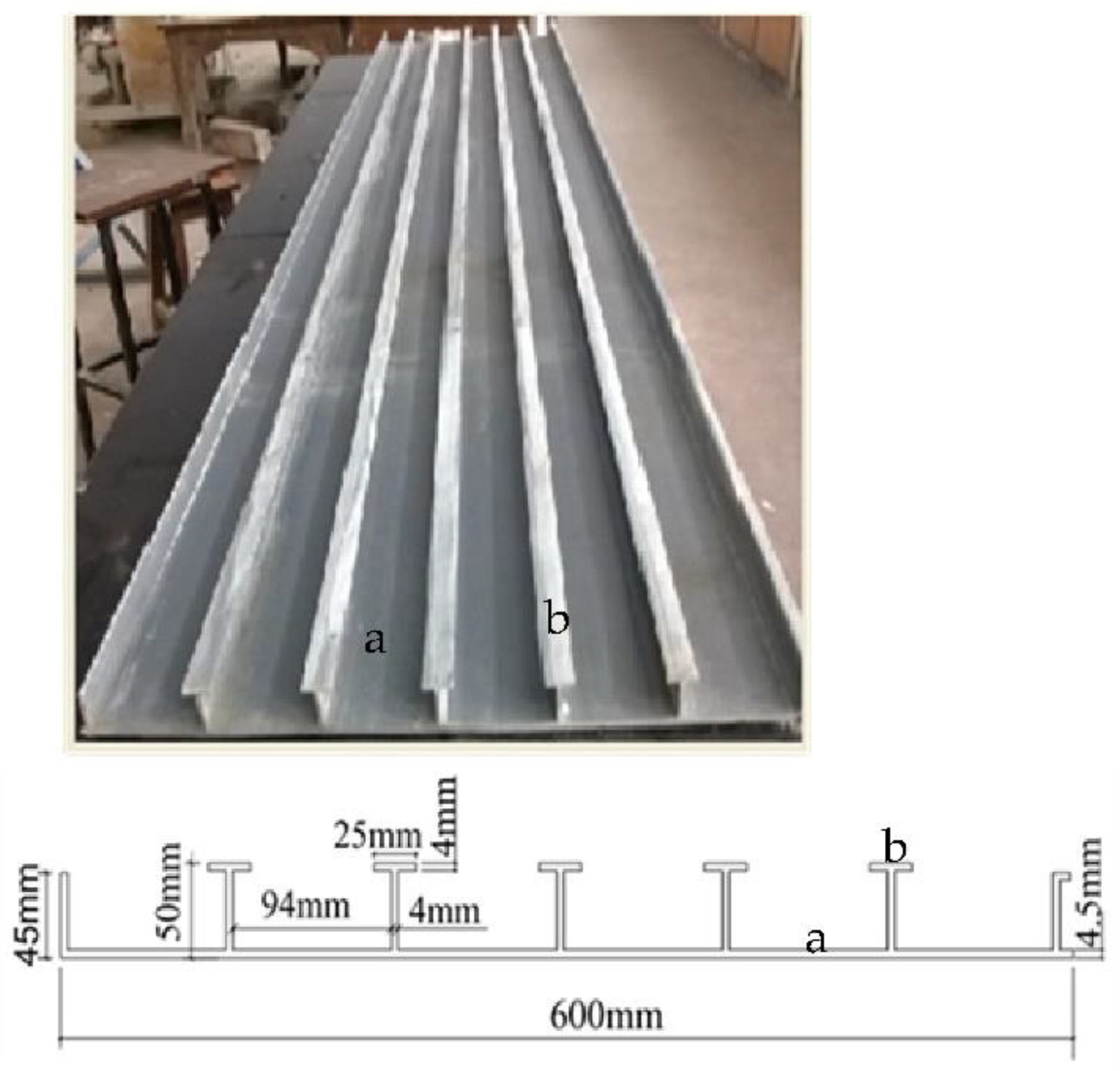
Figure 1. FRP-SIP used in the experiments.
Jcs 06 00313 g001
Figure 2. Details of the specimens. (a) FRP specimens with bond treatments. (b) Steel Reinforced specimen.
Jcs 06 00313 g002
Figure 3. Details of the test set-up.
Jcs 06 00313 g003
Figure 4. Load Deflection plot and failure mode for S series specimens. (a) SS1. (b) SC1. (c) SA1. (d) SG1.
Jcs 06 00313 g004
Figure 5. Load Deflection plot and failure mode for L series specimens. (a) LS3. (b) LC3. (c) LA3. (d) LG3.
Jcs 06 00313 g005
Figure 6. Envelop Plots. (a) S Series. (b) L series.
Jcs 06 00313 g006
Figure 7. Energy norms for different samples. (a) S Series. (b) L Series.
Jcs 06 00313 g007
Figure 8. Cumulative energy norms for different samples. (a) S Series. (b) L Series.
Jcs 06 00313 g008
Figure 9. Parameters included in the analysis.
Jcs 06 00313 g009
Table 1. Specimen Summary.
SpecimenSpan (m)Depth (m)Width (m)Tensile Reinforcement
SS110.200.60Steel bars (6–16 mm)
SC110.200.60FRP plank (without any bond treatment)
SA110.200.60Adhesively bonded FRP plank
SG110.200.60Aggregate bonded FRP plank
LS330.150.375Steel bars (5–12 mm)
LC330.150.375FRP plank (without any bond treatment)
LA330.150.375Adhesively bonded FRP plank
LG330.150.375Aggregate bonded FRP plank
Table 2. Properties of GFRP Profile.
Thickness
(mm)
Young’s Modulus (GPa)Tensile Strength
(MPa)
Volume Fraction
Avg.*1SD *2Avg.SD
Plate4.527.92.55375.55.860.35
Ribs423.82.2352.35.450.30
*1 Average. *2 Standard Deviation.
Table 3. Adhesive properties.
PropertiesValues
Epoxy contentTwo-part epoxy
Pot life45 min at 25 °C
ViscosityViscous Thixotropic
Elastic modulus5 GPa
Elongation at break0.4%
Tensile strength15 MPa
Flexural strength30 MPa
Bond strength8–10 MPa
Table 4. Summary of the Experimental Results.
SpecimenFailure Load
(kN)
Deflection at Failure (mm)Failure Mode
SS1297.773.11Concrete Shear
SC1176.322.65Interfacial bond
SA1453.514.27Concrete bond
SG1397.003.49Concrete bond
LS369.3030.10Flexure
LC342.0317.32Interfacial bond
LA3143.7457.91Concrete bond
LG3150.2456.43Concrete bond
Table 5. Neutral Axis Depth.
ParameterS Series SlabsL Series Slabs
Effective depth d (mm)187.73139.97
FRP effective stiffness Ef (GPa)26.2226.58
Reinforcement ratio ρ0.0400.048
Balanced reinforcement ratio ρb0.01410.0142
Elastic neutral axis depth ce (mm)41.2833.59
Ultimate neutral axis depth cover (mm)50.8841.96
Table 6. Analytical Results.
Type of SlabExperimentalEstimated Capacity (kN)
Capacity (kN)FlexureShearLimit
ACI440ACI440ACI318
S226.594872.38133.9134
L7511636.56262
Publisher’s Note: MDPI stays neutral with regard to jurisdictional claims in published maps and institutional affiliations.