Abstract
For several years, the aviation industry has seen dynamic growth in the use of composite materials due to their low weight and high stiffness. Composites are being considered as a means of building lighter, safer, and more fuel-efficient automobiles. Composite materials are the building material of a relatively new kind of unmanned aerial vehicle, commonly known as a drone. Incremental forming methods allow materials to be quickly formed without the need to manufacture conventional metal dies. Their advantage is the high profitability during the production of prototypes and a small series of products when compared with the conventional methods of plastic forming. This article provides an overview of the incremental forming capabilities of the more commonly produced aluminium- and titanium-based laminates, which are widely used in the aircraft industry. In addition, for composites that are not currently incrementally formed, i.e., aramid-reinforced aluminium laminates, the advantages and potential for incremental forming are presented.
1. Introduction
Composite materials, depending on their structure and purpose, exhibit many advantages over metallic materials [1,2]. These are, e.g., reduced weight, increased strength and stiffness, wear resistance, resistance to thermal shock and fatigue processes, and resistance to dynamic loads [3,4,5]. Moreover, they exhibit high resistance to environmental conditions, including corrosion and fire resistance, and high durability [6,7,8]. Currently, the largest beneficiaries of the use of composite materials are the transport industries, i.e., the automotive [9] and aircraft industries [10,11]. Recently, with the popularisation of unmanned aerial vehicles (UAV), composites allow for a desirable reduction of their mass allowing for more efficient use of drives [12,13]. The use of composites can reduce overall UAV weight by 15–45% depending on the extent of composite use [14].
The history of fibre-metal laminates (FMLs) goes back to the 1950s and 1960s [15]. The first FMLs were produced for aviation in the 1980s at Delft University of Technology (The Netherlands) [16]. These laminates were a combination of aluminium alloys EN AW-2024 and EN AW-7075 with aramid fibres. The resulting aramid–aluminium laminates (ARALLs) were, however, characterised by a low strength of the fibre-matrix interface. Hybrid composites of glass-reinforced aluminium laminates (GLAREs) are a solution consisting of 2 to 6 layers of EN AW-2024-T3 and EN AW-7475-T761 aluminium sheets with a thickness of 0.2 to 0.5 mm. Between the metal layers lie alternating layers of glass fibres bonded with epoxy resin. GLAREs have a stiffness that is lower than a single layer of aluminium, which is attributed to the lower stiffness of the glass fibre layers [17,18]. FMLs with carbon fibres, commonly known as CARRALs (carbon-reinforced aluminium laminates), are made of a composite of layers of a polymer-reinforced with carbon fibres pre-impregnated with epoxy resin and layers of aluminium. CARRAL laminates show an approximately 10% higher tensile strength than GLAREs for the same fibre volume fraction [19]. CARRALs also offer a higher specific modulus, higher energy absorption, and excellent fatigue resistance compared to ARALLs [20,21]. The more commonly used interlacing composite layers in FMLs can be classified by their polymer matrices and reinforcing fibres (Figure 1).
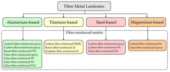
Figure 1.
Classification of fibre metal laminates.
In addition to aluminium alloys, sheets of other non-ferrous metals, i.e., titanium alloys and magnesium alloys are used for the production of layered composites. Titanium-based FMLs (Ti-FMLs) based on high temperature composites such as polyetherimide (PEI) and polyetheretherketone (PEEK) have been considered as suitable candidates which satisfy the requirements associated with these potentially aggressive loading environments [22,23]. Polyetherketoneketone (PEKK) offers the advantage that its processing temperature is lower than PEEK whereas its glass transition temperature is higher [24]. In 1994 NASA started to develop TiGr, which is an FML system consisting of titanium and graphite fibre-reinforced polymer [25]. The use of magnesium-based FMLs is limited because Mg alloys have poorer mechanical properties than Al. However, magnesium alloys have, in fact, an average of 35% lower density than aluminium, and are also cheaper [26].
In the 20th century, FML components were commonly manufactured using bending and lay-up techniques. These techniques have a major limitation—only components with a simple geometry can be manufactured by this method. In the last two decades, research interest has been drawn to producing complex-shaped FML components via die forming technologies. In order to produce single curvature FML components, press-brake bending processes are used [27]. However, such a method is limited by the low failure strain of the embedded fibres. Large panel components are fabricated using incremental sheet forming (ISF) [28,29] or the shot peening process [30,31]. The material is formed using an indentation impact that creates plastic deformations. In laser forming, the surface of the component is heated by laser beam irradiation and the resultant thermal stress leads to a change of shape in the scanning path of the beam [32,33].
Die forming techniques of FML fabrication include stamping [34,35], hydroforming [36], and electro-magnetic forming (Figure 2) [37]. Stamping involves forming the sheet of the composite with a punch, while the sheet is between the die and the blank holder. This process can be carried out in cold forming conditions or at elevated temperatures. Tools can also be cooled. Hydroforming works by forming FMLs with the help of fluid pressure. This process is usually used to form tubular components with low formability and requiring superior surface quality. The limitation of this method is the high cost of the stamping die compared to conventional sheet metal forming. Electromagnetic forming (EMF) belongs to the methods of forming at high speeds and using the Lorentz force generated in a pulsed magnetic field generated by two circuits conducting a rapidly changing electric current [38,39]. During EMF, the high dimensional and shape accuracy of the components and a high efficiency are achieved, and it is possible to increase the plastic properties of the sheet using several pulses of current, the first of which is used to heat the material. The formability of FMLs is determined by the deformation behaviour of both the fibre-reinforced polymer (FRPs) layers and the metallic layers. The understanding of the metal-FRP interfacial behaviour is less adequate than that of metals; thus, forming defect-free FMLs remains a major challenge [40].
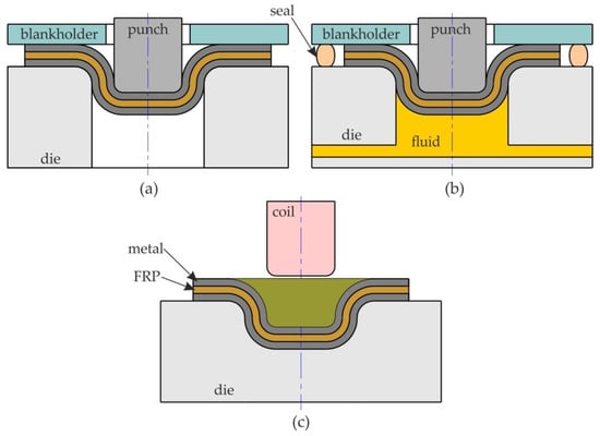
Figure 2.
Die forming methods: (a) stamping, (b) hydroforming, and (c) electromagnetic forming.
Laminated ISFed metal sheets can be used in the fabrication of parts with different inner and outer conditions such as mechanical strength, wear resistance, and corrosion. In many applications, particularly for large pressure vessels designed for high pressure, titanium clad steel construction can be very economical compared to solid construction [41].
The technique of incremental forming has been well known for more than half a century, but after the popularisation of numerically controlled machines it found wide application in the 21st century. Initially, incremental forming was used to form the sheet metal, and then it was noticed that FMLs could also be dieless and formed relatively quickly. Currently, no review has been found in the literature which is solely devoted to the incremental forming of FMLs used in the aircraft industry (aluminium- and titanium-based composites) nor are the limitations of ISF in this area reported. This article provides an overview of the incremental forming capabilities of the more commonly produced aluminium- and titanium-based laminates. In addition, for composites that are not currently incrementally formed, i.e., aramid-reinforced aluminium laminates, the advantages and potential for incremental forming are presented.
2. Incremental Sheet Forming Methods
Parts that are manufactured by the incremental forming process present some imperfections such as geometrical and dimensional defects, as well as poor surface roughness. These imperfections result from the employment of sheet forming methods and the use of process parameters (e.g., tool diameter, vertical pitch, and trajectory, etc.). To prevent imperfections, researchers and manufacturers have tried to optimise the process parameters used in incremental forming using different methods to improve the geometry of the parts produced and their surface quality.
For instance, we can cite incremental sheet metal forming using a simple small tool, also known as “forming without a mould”. This method was patented in 1967 by Leszak [42] before it was applied in practice. Subsequently, it was adapted and utilised by many researchers [42,43,44,45,46,47].
In fact, there are two types of asymmetric incremental forming (Figure 3):
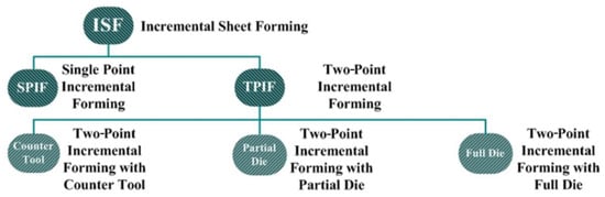
Figure 3.
Methods based on the ISF Process.
- -
- Two-Point Incremental Forming (TPIF);
- -
- Single Point Incremental Forming (SPIF).
Two-point incremental forming or positive forming deforms sheet metal locally using a hemispherical device, which moves on the convex surface of the part, and a counter tool or a mould to make full or partial contact with the sheet [48,49,50] (Figure 4). The die and the blank holder can move along the vertical axis.
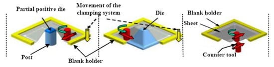
Figure 4.
Two-point incremental forming (adapted with permission from Ref. [51], Copyright 2005 CIRP).
Single-point incremental forming or “negative forming” consists in deforming sheet metal with a small hemispherical tip device, which follows a predefined track [52,53,54], to obtain the final shape required [51,55,56,57]. This technique uses a blank holder and a die without employing a counter die [48]. SPIF is illustrated in Figure 5.
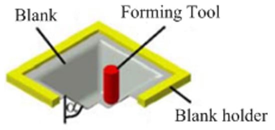
Figure 5.
Single-point incremental forming (adapted with permission from Ref. [48], Copyright 2004 CIRP).
Although each of the processes mentioned above has its advantages, single-point incremental forming has been widely used by scientists and researchers because it can be easily applied using CNC machines or robots to produce parts having different shapes [58] and is less expensive than two-point incremental forming. Moreover, it can integrate new technologies such as a high-pressure water jet and lubrication.
2.1. Water Jet Incremental Forming (WJIF)
Water Jet Incremental Forming (WJIF) combines the SPIF process with water jet technology as an alternative method of incremental forming [59,60,61,62,63,64,65,66,67]. The main difference between SPIF and WJIF is that, instead of using a rigid tool, the former uses a high-pressure and high-velocity water jet as the forming tool. The major benefit of WJIF is that it does not include any rigid contact between the tool and the part and does not utilise any type of lubricant. Indeed, WJIF was first suggested by Iseki as a means of deforming 0.3 mm aluminium sheets by applying a simplified predictive model [68]. Jurisevic et al. [59] showed that the WJIF process employs “relative water jet diameter” that represents the ratio between water jet diameter and sheet thickness. Moreover, Lu et al. [66] developed a prototype System ISF-WJ machine by designing different nozzles. They proved that the ISF-WJ process can enhance the surface finish of the deformed parts without lubrication. Figure 6 shows an example of a device used to carry out the ISF-WJ process developed by Lu et al. [66].
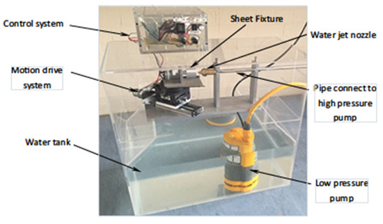
Figure 6.
Device for incremental forming by water jet (adapted from Ref. [66]—this is an open access article distributed under the terms of the Creative Commons CC BY license, which permits unrestricted use, distribution, and reproduction in any medium, provided the original work is properly cited).
2.2. Hot Incremental Forming
Hot incremental sheet forming methods were developed for forming hard-to-deform sheets in conditions of cold working. The technique consists of heating the sheet metal using various methods: the frictional interaction of the tool, the induction heating method—with the use of hot working fluid—and hybrid heating by a combination of several methods. Typical materials formed at elevated temperatures are titanium alloys, magnesium alloys, aluminium alloys, and stainless steels. Warm single point incremental forming (WSPIF) consists of implanting a cartridge into the device die during the forming tests (Figure 7). In order to have a contact surface that allows it to be heated by conduction, the blank should be placed on the die during this process. Indeed, this technique is intended to enhance sheet formability and reduce the forming forces of titanium [69], AZ31 magnesium alloy, and EN AW-5055 aluminium alloy [70].
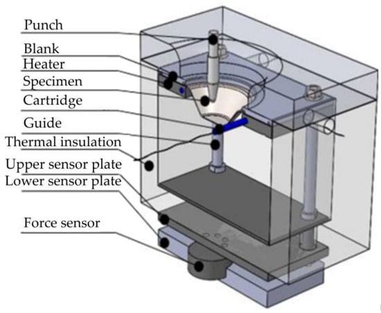
Figure 7.
The device used in WSPIF (adapted with permission from Ref. [69], Copyright 2020 The Brazilian Society of Mechanical Sciences and Engineering).
2.3. Ultrasonic Assisted Incremental Sheet Forming
In the ultrasonic-assisted incremental sheet forming (UISF) process, high frequency vertical vibration is applied to the tool tip. The vibration amplitude of the forming tool is checked by the ultrasonic generator and the ultrasonic transducer is attached to the spindle of the machining centre. This method is intended to improve the quality of the surfaces [71], minimise the forming forces [72,73], and increase the formability of the sheets [74]. Figure 8 shows the experimental configuration of an ultrasonic incremental forming process.
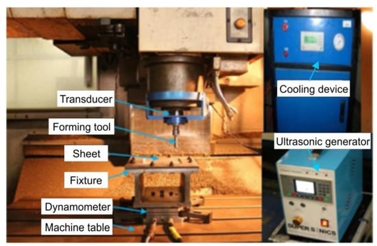
Figure 8.
The experimental configuration of the UISF process (adapted with permission from Ref. [75], Copyright 2019 the Authors).
3. Achievements in SPIF of Metal-Based Composites
Over the years, the ISF technique has mainly been applied to metallic materials. Different non-metallic materials were considered for ISF in the first ten years of the 21st century. The mechanical and formability characteristics of metal-based composite sheets were promising.
3.1. Glass-Reinforced Aluminium Laminates
Aluminium alloy layers are used to create FMLs, of which Glass Laminate Aluminium Reinforced Epoxy (GLARE) is the most common. Thin layers of aluminium sandwiched between layers of glass fibre prepregs make up GLARE, which is held together by epoxy resin acting as the matrix. GLARE was created at Delft in 1987 and a patent for GLARE with the number US5039571 A was issued in 1988 [76]. Instead of aramid fibre, this invention focuses on aluminium layers mixed with glass fibre-reinforced layers. GLARE is a unique material for aircraft applications [77] and is now mainly used to construct modern aircraft fuselages. The initial tests of GLARE, created at Delft in 1987, took place aboard the Airbus A380 superjumbo on May 16, 2001 [78]. GLARE has different grades based on the aluminium type, the glass fibre prepreg, and the resin. The most common type of aluminium used in GLARE laminates is 2024-T3. Only the Grade 1 laminates of GLARE employ a distinct kind of aluminium; nevertheless, this kind of GLARE is not typically used in the aircraft sector. These aluminium layers typically have a thickness of 0.3 or 0.4 mm [79]. The possibility of using SPIF as a technique to produce the double-curved aluminium sheets used in GLARE laminates in a dieless manner has been examined in a master’s thesis from Delft University of Technology. To determine whether this approach could accomplish the needed speed and accuracy, a small-scale experimental setup was deployed and translated to a large-scale production line, such as the Airbus A320. The results of the studies indicated that accuracy could be attained using Micari’s suggested corrective procedure [80]. Three different typologies of error can be detected in the final component when the SPIF tool action is removed (Figure 9): sheet bending, sheet springback [81], and the pillow effect. Sheet bending can be easily reduced or eliminated with a simple backing plate. Elastic springback of the deformed material reduces the height of the drawpiece when the punch action is relaxed. The pillow effect changes the curvature of the drawpiece bottom.
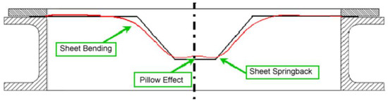
Figure 9.
Geometrical errors during the incremental forming of a conical drawpiece (adapted with permission from Ref. [80], Copyright 2007 Elsevier B.V.).
The biggest problem, however, is with the processing speed, which necessitates a high feed rate and small step size. As a result, the manufacture of the Airbus A320’s fuselage panels cannot use the incremental sheet forming method. However, due to the lower production volumes needed for the leading edges and empennage, it is possible to create these parts using this method [79]. A new product was formed using incremental sheet forming (ISF) fabricated from the GLARE composite of Alclad 2024-T3 aluminium alloy sheets to create a thin-walled structure with a longitudinal rib as a stiffener. The product was evaluated using five different composite testing techniques. In the uniaxial compression test of GLARE-based rib-stiffened panels, an evident increase in the critical force at which buckling occurs has been clearly proven. The critical force for GLARE-based rib-stiffened panels was an average of 15,370 N, whereas the critical force for the non-embossed variation was 11,430 N, representing a 34.5 percent increase in critical force [82]. In studies on the application of SPIF on composite materials, an aluminium sheet was formed into a mould using the SPIF technique, and the mould was then used to make composite parts. Kevlar, Glass, and Kevlar were layered over the mould and then rolled into the form using plastic rollers. The results showed that the FML did not pass the test. The collapse of the SPIF components was caused by a crack that started to appear and grow. The core material protected the aluminium layer below from stress. Because the core material cannot be squeezed, the bottom sheet’s thickness was only decreased by a small amount. The formability of the SPIF components was limited by the formation of creases along the sloping wall [83].
3.2. Carbon-Reinforced Aluminium Laminates
Lightweight bodies are more and more frequently being developed for the aircraft and the automotive industries in order to save energy. For the promotion of this trend, it is necessary to form metallic sheets with a high strength-to-weight ratio. Fibre metal laminates (FMLs) are bonded together to create a material with these unique properties from the original materials. Carbon Fibre Reinforced Aluminium (CARALL) is one class of FML which has grown in importance across a wide range of industries as a practical way to address this growing demand. The first tests on laminates that were reinforced with carbon and aramid fibres, that included flight simulation, were conducted in 1978 [84]. Later, FMLs with high strength qualities and significantly stiffer laminates were in demand, and CARALL was researched and produced from ARALL [85]. CARALLs have not found application in the incrementally formed components.
3.3. Aramid-Reinforced Aluminium Laminates
The composites used in aviation [86] have also developed in the direction of combined aluminium shells (plates) with an aramid-reinforced matrix as the core material. The aramid material is a shortened term for aromatic polyamide, which is commonly used in the form of long, heat-resistant polymer fibres. The polymer’s chain molecules are strongly oriented along the fibre axis with significantly better mechanical properties in the longitudinal than in the transverse direction [87]. Through this a proper structure, frequently woven in 2D or even 3D [88], needs to be applied to the composite material (Figure 10).
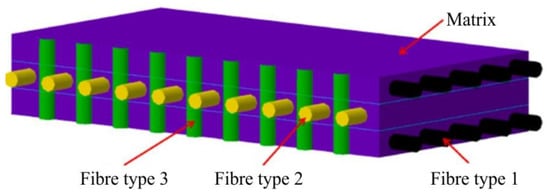
Figure 10.
Schematic 3D diagram of the structure of fibre reinforced composite with fibres oriented in the matrix in three orthogonal directions: longitudinal (type 1), crosswise (type 2), and through the thickness of the matrix (type 3) (adapted with permission from Ref. [88], Copyright 2021 Elsevier Ltd.).
The so-called aramid-reinforced aluminium laminate has already been known as a light composite material for decades [89], having been first presented in 1982 by the Aerospace Department of Delft University of Technology in the Netherlands. The ARALL abbreviation is also used for the first commercial aluminium-based aramid composite developed by the ALCOA company. These laminates are obtained by bonding thin aluminium layers and prepregs of aramid layers as presented in Figure 11 [90]. In the first ARALL materials, the high strength aramid fibre was inserted into the structural epoxy adhesive, which served as a matrix for the prefabricated prepregs.
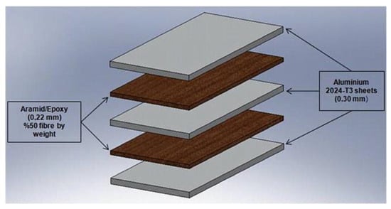
Figure 11.
Schematic presentation of ARALL fibre metal laminates (adapted with permission from Ref. [90], Copyright 2011 Elsevier Ltd.).
Sinmazçelik et al. have presented a strict manufacturing procedure for ARALL ranging from proper preparation of the aluminium sheets to the adhesive bonding of aluminium layers using the thermoset adhesive system [90]. The layers of aluminium plates and aramid fibres in the matrix are normally bonded together at elevated temperatures in a press or an autoclave to bind the prepreg material with the aluminium sheets. A vacuum chamber can be applied [91] while some authors [92] also report that a vacuum-assisted resin transfer moulding process (VARTM) is used.
In the first period of their use in the aviation sector there was no idea of forming these composites into the final shape of the part. These parts are produced by classical composite manufacturing techniques and applied in various aviation applications. However, Vogelesang had already analysed the composite plasticity, formability, and impact strength, as well as the possibility of machining the material for the final finishing of the part and had also found some parallels with metals. Hai et al. [93] have determined that failure under tensile loading is dependent on the amount of aramid resin. In particular they show that ARALL laminates have a high resistance to the growth of fatigue cracks and express a high tensile yield strength. Through this, the load/mass relationship is favourable for their application in the aviation sector. It is reported that up to 30% mass can be saved by the use of ARALL [94,95] in airplane wings.
However, the ARALL matrix from thermosets that is the most used is less appropriate for further processing by incremental forming and other deformation processes since they express small strains up to the breaking point [96]. For this purpose, the matrix from thermoplastic-like polypropylene (PP) was applied [97]. In comparison with the commonly used epoxy matrix, higher strains are also attainable with the use of PP (Figure 12).
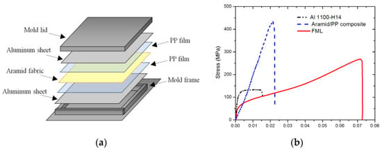
Figure 12.
(a) The structure of Al-PP–aramid composite and (b) a comparison of the flow curves of the Al, composite core, and FML material (adapted with permission from Ref. [97], Copyright 2017 Elsevier Ltd.).
In recent years the aramid–epoxy structure was replaced by epoxy incorporating aramid nano-fibres. Jung and Sodano [98] have shown that the strength of epoxy resin can be improved by using a nano-filler of aramid fibres (Figure 13a) thus enabling sufficient strains to form during incremental forming. At the same time, the tensile stress of the material was also increased. A similar improvement in mechanical properties as a result of enrichment of the polymer matrix with nanoparticles without degradation of formability has been demonstrated by Borić et al. [99] for the PA66 material. The influence of material formability is also dependent on the type of aramid nanofibres [100,101] ranging from 5% elongation, at break for epoxy-reinforced with aramid pulp (AP) fibres as the reference material, and 100% larger elongation in the case of aramid nanofibres (ANF) (Figure 13b). Kuang et al. [101] have obtained a 60% increase in tensile strength by incorporating the ANF into the polyurethane matrices. However, in addition the elongation at break did not exceed 2.8% in this example.
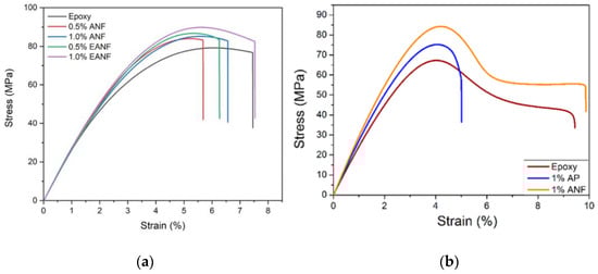
Figure 13.
(a) strain improvement by various amounts of ANF (adapted with permission from Ref. [98], Copyright 2020 Elsevier Ltd.) and (b) enhancement of attainable strains of ANF versus AP (adapted with permission from Ref. [100], Copyright 2017 American Chemical Society).
Since ISF processes have developed in parallel with the early ARALL laminates and are primarily being applied to metals, there were no applications of ISF in the early stages of finding applications of ARALL. With the increased complexity of aviation parts following the minimisation of the strength/mass ratio, more advantageous and less common manufacturing technologies were also sought to form the composite workpieces into their final shape. In particular, the behaviour of laminates must be well understood in order to apply forming processes on these structures [102,103]. For this purpose, research work focused on understanding the failure mechanisms of ARALL structures under various loading conditions which appear during ISF processes. In the work of Liu et al. [104] a comprehensive overview was presented of the incremental forming of various composite materials ranging from fibre metal laminates, carbon fibre-reinforced plastics, glass fibre-reinforced plastics, multi-metal composites, and the Al-PP-Al composite. The deformation criteria as well as material rupture were shown and correlations with particular loading conditions were sought. Membrane strains, as well as through-thickness shear strains, are the main deformation criteria appearing during ISF. Both criteria are critical for the definition of an attainable strain state without fracture. Fracture of the ARALL material appears in the form of delamination or as fracture without delamination [96]. Silva et al. [105] have emphasised the problems of various stress states appearing during the ISF process. During the incremental forming process, the main stress conditions are shear, bending, and tensile loading of the material. In particular, shear loading is emphasised on the surface of the formed material [106] while the entire sheet is locally exposed to tensile loading and bending during the forming process. Hassan et al. emphasised three typical failure modes observed in polymers [107]. However, those failure modes are not directly transferred to the aluminium-based composite materials. The failure modes of such composite structures need to be further analysed.
The early stage ARALL materials [108] consisting of aluminium sheets and aramid fibres in epoxy matrices have relatively small strain potential and lower strength in comparison with other fibre metal laminates. Therefore, they are currently only used in the aviation sector in those applications where the main consideration is a decrease in the mass of the part. On the other hand, aluminium-based composites with thermoplastic matrices and aramid nanofibres are very promising materials with larger deformation potential. Ding et al. [109] have analysed the formability temperature range of various thermoplastics and defined their applicability range (Figure 14). Such materials can also be formed incrementally at elevated temperatures, which can increase their formability.
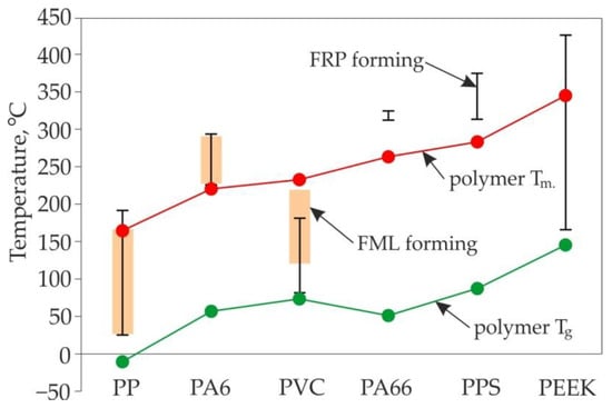
Figure 14.
Forming temperature windows of FMLs, prepared on the basis of [109].
3.4. Aluminium-Based Bimetallic Sheets
A bimetal sheet is a multi-layer sheet that combines two or more layers of metal [110]. Rolling and explosive welding are the most popular methods of manufacturing bimetallic sheets. The most heavily investigated bimetallic sheet, Al-Cu, offers the advantages of both copper and aluminium [111]. Copper offers high corrosion resistance, and high electrical and thermal conductivity. Aluminium is stiffer and cheaper than copper.
During SPIF of bimetallic aluminium-based sheets the most heavily investigated phenomenon is the effect of the layer arrangement on the delamination and formability of the workpiece material. Gheysarian and Honarpisheh [112] investigated the fracture depth of explosively welded Al/Cu bimetallic sheets in SPIF. Various tool diameters, sheet arrangements, and tool paths were analysed using an analysis of variance (ANOVA). It was found that the formability of this sheet increased by decreasing the tool diameter by about 5% and by decreasing the step-down by about 12%, because the strain on the sheet decreased. The formability was also improved by about 3% when Cu was the top layer, because more stress occurs at the underside aluminium layer. Gheyserian and Honarpisheh [113] also undertook mathematical analysis of the incremental forming of explosively welded Al/Cu bimetals. Tool path, vertical step, tool diameter, and layer arrangement were the input parameters. Surface roughness (Ra and Rz parameters), forming time, maximum variation of thickness, and mean forming force were the outputs. It was found that the value of the surface roughness parameters increased with the decreasing the tool diameter, by increasing the vertical step, and by using Al as the top layer. On the other hand, increasing the tool diameter and vertical step using Al as the top layer caused an increase in the forming forces. In another paper, Honarpisheh and Gheysarian [114] experimentally studied the process parameters in SPIF of truncated pyramids from Al/Cu bimetallic sheets. They found that formability increased with increasing tool diameter, a spiral tool path, and when Cu formed the top layer. Honarpisheh et al. [110] have carried out multi-response optimisation of SPIF of Al/Cu bimetal drawpieces with a hyperbolic profile using response surface methodology (RSM). The interaction of the rotational speed, tool diameter, sheet arrangement, and step-down were evaluated in relation to wall thickness at fracture and fracture depth using an ANOVA. The main effect plots revealed that a higher level of step-down with a smaller tool diameter and SPIF forming from the Cu side, provided a greater fracture depth. On the other hand, a greater thickness was obtained when tool rotational speed and step-down were greater, and the sheet arrangement was Al. A comprehensive study on the deformation behaviour of SPIFed Cu/Al composite sheets has been provided by Liu and Li [115]. Investigations were carried out on Al1060-O aluminium and C10100 copper composite sheet fabricated by cold roll bonding. In order to improve the surface finish of the drawpieces the authors tested different strategies with regard to scallop height. The Al/Cu layer arrangement exhibited greater formability and a larger forming force compared to the Cu/Al layer arrangement, because the exterior, thinner but stronger, Cu layer could endure more deformation due to stretching. This can be explained by the fact that the deformation mode of layer-up sheet tends to a compression state and that of layer-down sheet tends to a stretching state. The formability of aluminium alloys in SPIF can be increased significantly by providing a tool with which to minimise the friction material by adjusting the rotational speed to the feed rate [116]. Alinaghian et al. [117] investigated the residual stress distribution of Al/Cu bimetallic drawpieces produced by the SPIF process. The results of the incremental hole-drilling method revealed that smaller step-down values produced smaller residual stress in the SPIF of Al/Cu bimetal. Moreover, step-down can be considered as the most effective parameter with which to increase or decrease residual stress.
Jajali et al. [118] developed the forming limit diagram of Al/brass (65 wt.% copper) roll-bonded sheets through SPIF. It was concluded that the formability of brass/Al (brass was the upper layer and aluminium was the bottom layer) was more than that of Al/brass. In the following paper, the ISF parameters such as forming limit angle, step-down, and thickness distribution were investigated.
3.5. Titanium-Based Bimetallic Sheets
The mainstream of incremental sheet forming titanium composites focuses on explosively welded sheets. In recent years, the post treatment of explosively welded materials has been an interesting field which has opened up a new area of scientific research. In established research, only commercially pure titanium with low-carbon steel is considered. Such a composition allows one to reduce the cost of the final part while simultaneously meeting the required design criteria—high strength, wear, and corrosion resistance. In this regard, these products are increasingly being used in a variety of fields, such as aerospace, automobiles, heat exchangers, and pressure vessels [119].
Sakhtemanian et al. [120] investigated an explosively welded low carbon steel (St)/commercially pure titanium Grade 2 (CP-Ti G2) bilayer ISF with a numerical approach and experimental verification. The authors applied a novel algorithm for tool movement through the sheet surface, where the boundary conditions for the forming tool were processed from the Automatically Programmed Tool file from computer-aided manufacturing software. Vertical stepdowns of 0.1 mm, 0.2 mm, and 0.3 mm were selected and a constant tool feed rate of 700 mm/min was applied. The steel layer was on the tool contact side of the frustum shaped 45° pyramid, that was the desired product. It was found that the vertical step-down mainly affects the forming forces; however, it decreased forming time. Elevated force can be associated with distortion of ferritic grains and the creation of fibrous structures. The finite element method, in addition to exhibiting good agreement with the experiment, resulted in about a 15% higher force, leaving a safe margin for implementation. The authors also measured specimen strength and micro-hardness; it was found that a larger vertical step-down contributed to its growth. This phenomenon has been confirmed by microstructural studies showing a grain size reduction as vertical step-down increased. SEM analysis revealed surface scratches that deepened with vertical step-down rings. In further research [41], the authors considered the layer arrangement of CP-Ti G2/low-carbon steel. Consideration was given to the friction coefficient between the tool and the sheet composite. It was found that the low-carbon steel/CP-Ti G2 configuration resulted in lower friction throughout the entire scope of the experiment. Furthermore, contact of the tool with the Ti layer caused deterioration of surface quality. It caused greater adhesion compared to the steel layer, resulting in surface chipping, while only scratches appeared in the steel layer. The arrangement of steel/CP-Ti G2 affects force reduction by up to 25% compared with the converse. Grain size reduction has been noted with steel/CP-Ti G2; however, the density of twins did not change in the Ti layer. However, in the case of CP-Ti G2/low-carbon steel, the twinning density in the Ti layer increased strongly (Figure 15), but the grain size of the steel layer remained unchanged.
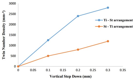
Figure 15.
Evolution of twin density as a function of vertical step-down in the two arrangements (St—steel) (adapted with permission from Ref. [41], Copyright 2017 Springer-Verlag London Ltd., part of Springer Nature).
A novel ultrasonic-assisted approach has been presented by Sakhtemanian et al. [73]. Ultrasonic vibration induces heat generation in the tool contact zone, which leads to a reduction in forming force and friction coefficient. The authors investigated numerical modelling with experimental verification within the parameter range of vertical step-downs of 0.1–0.3 mm and tool feed rates of 400–1000 mm/min. To verify the differences in ultrasonic-assisted forming, similar runs have been undertaken without tool vibration. The truncated pyramid of the geometry of the specimen was chosen to be formed from a steel/CP-Ti composite with a top layer of low carbon steel. The authors proposed a theoretical model explaining the correlation of the tool and the sheet temperature with the ultrasonic generator, which revealed a rapid increase in the tool temperature, then stabilisation at a constant level. Ultrasonic vibrations, which were also affected, reduced both the coefficient of friction, by up to 37%, and the formation force, compared to those without ultrasonic treatment. Furthermore, the ultrasonically formed specimens showed equiaxed fine grains along the primary grain boundaries and should be considered as the reason for continuous dynamic recrystallisation causing material softening.
Further FEM analysis carried out by Abdelkader et al. [121] focuses on an arrangement which includes a low carbon steel composite layer and CP titanium grade 2. The titanium layer was found to have contact with the tool to reduce the maximum forming forces. The significant effect of the vertical step-down on the thinning of the composite was emphasised; the greater the vertical step-down, the greater the thinning that took place. In addition, a thicker wall was achieved for the CP-Ti G2/steel composite. The research was extended to compare steel/CP-Ti G2 composites with an independent single CP-Ti G2 sheet [122]. The experiment covered 3 levels of the following parameters: wall angle, sheet thickness, vertical step-down, and layer arrangement. Bilayer composite variants induced lower forming forces than a single CP-Ti G2 sheet. In addition, the bimetallic sheet was characterised by an improved surface quality compared to the single-layer sheet. The layered composites showed less thinning than the monolayer of titanium (Figure 16), as well as a more homogenous thickness distribution.
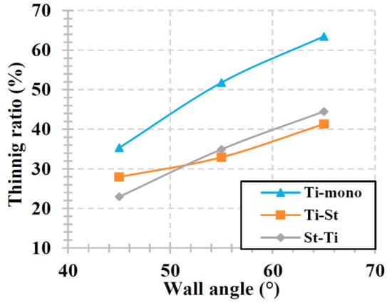
Figure 16.
The effect of wall angle on the thinning ratio (initial sheet thickness t0 = 1.5 mm, vertical step size Δz = 0.5 mm, St—steel) (adapted with permission from Ref. [122], Copyright 2020 The Author(s). Published by Elsevier B.V.).
4. Conclusions
This article presents the current state of knowledge and the results of research related to incremental forming of metal-based composites including bimetallic sheets. ISF technology enables the dieless production of components in a cost-effective small series and the forming of products from materials with limited deformation in conventional sheet metal forming processes. Although the methods of ISF are not yet widely popularised in the field of metal-based composites, a limited number of studies already indicate some limitations and advantages:
- The main problem to be solved when forming composite materials is the accumulation of resin in the bottom of the drawpiece. The cyclic circumferential movement of the tool causes non-uniform distribution of the resin in the walls of the component;
- Single point incremental forming allows an increase in the strength and improvement in the specific stiffness of FML components;
- The composite core of FMLs prevents local load transfer to the bottom plate—this is the main cause of wrinkling;
- One limitation in the use of ISF is the relatively long processing time. It is suggested that multiple forming tools could be used to work simultaneously on the same components. This effect can be achieved by using multi-tool heads or robots;
- Many authors draw attention to the shortcomings of predictive models for incremental forming processes. It turns out that due to many phenomena and forming parameters simultaneously affecting the formability and accuracy of SPIF-ed components, the predictive models developed for various materials are too general;
- Single point incremental forming of ARALLs is of limited application due to the low strength of the fibre-matrix interface;
- The behaviour of the composite sheet during the ISF process differs from monolayer sheets and depends on the arrangement of the layers. The positioning of layers plays an important role in grain size and twinning density. Friction conditions between the surface of the forming tool and the bimetallic sheet affect the surface quality, the forming force variations, and the formability of the sheet metal;
- Improvement of the formability of bimetallic sheets can be obtained by using the ultrasonic vibration tool, which additionally allows the user to reduce the value of the coefficient of friction by up to several dozen percent depending on the process conditions. During SPIF with and without vibration, the forming force decreases due to the application of ultrasonic vibration to the tool.
Author Contributions
Conceptualization, T.T.; methodology, T.T., S.M.N., T.P., K.B. and M.S.; validation, T.T., S.M.N., T.P., K.B. and M.S.; resources, T.T., S.M.N., T.P., K.B. and M.S.; data curation, T.T., S.M.N., T.P., K.B. and M.S.; writing—original draft preparation, T.T., S.M.N., T.P., K.B. and M.S.; writing—review and editing, T.T., S.M.N., T.P., K.B. and M.S.; project administration, T.P. All authors have read and agreed to the published version of the manuscript.
Funding
This research was partially funded by the Slovenian Research Agency, research core program No. P2-0248.
Institutional Review Board Statement
Not applicable.
Informed Consent Statement
Not applicable.
Data Availability Statement
The data presented in this study are available on request from the corresponding author.
Acknowledgments
The research reported in this paper is part of project no. BME-NVA-02, implemented with the support provided by the Ministry of Innovation and Technology of Hungary from the National Research, Development and Innovation Fund, financed under the TKP2021 funding scheme.
Conflicts of Interest
The authors declare no conflict of interest.
References
- Kadhum, A.M.; Faris, S.T.; Al-Katawy, A.A. Development and properties of fiber metal laminate used in aircraft wing by using epoxy-novolac. IOP Conf. Ser. Mater. Sci. Eng. 2019, 518, 032034. [Google Scholar] [CrossRef]
- Mukesh, A.M.; Hynes, N.R.J. Mechanical properties and applications of fibre metal laminates. AIP Conf. Proc. 2019, 2142, 100002. [Google Scholar] [CrossRef]
- Tiwary, A.; Kumar, R.; Chohan, J.S. A review on characteristics of composite and advanced materials used for aerospace applications. Mater. Today Proce. 2022, 51, 865–870. [Google Scholar] [CrossRef]
- Liu, X.; Tian, S.; Tao, F.; Yu, W. A review of artificial neural networks in the constitutive modeling of composite materials. Compos. Part B Eng. 2021, 224, 109152. [Google Scholar] [CrossRef]
- Żaba, K.; Nowosielski, M.; Kita, P.; Kwiatkowski, M.; Tokarski, T.; Puchlerska, S. Effect of heat treatment on the corrosion resistance of aluminized steel strips. Arch. Metall. Mater. 2015, 60, 1825–1831. [Google Scholar] [CrossRef]
- Al-Mosawi, A.I.; Al-Maamori, M.H.; Wetwet, Z.A. Mechanical properties of composite material reinforcing by natural-synthetic fibers. Acad. Res. Int. 2012, 3, 108–112. [Google Scholar]
- Sluzalec, A. On random characteristics of composite materials. Mater. Sci. Technol. 2013, 29, 1272–1274. [Google Scholar] [CrossRef]
- Subesh, T.; Yogaraj, D.; Ramesh, V. Characterization of fiber metal laminates, bonding and manufacturing methods. Int. J. Innov. Technol. Explor. Eng. 2019, 8, 1062–1065. [Google Scholar] [CrossRef]
- Chatys, R.; Kuta, K.; Panich, A. Composite body construction optimization and technological design of an electrically powered race car. Zeszy. Naukowe Politech. Rzeszow. Mech. 2018, 90, 421–431. [Google Scholar] [CrossRef]
- Vlot, A.; Vogelesang, L.B.; de Vries, T.J. Towards application of fibre metal laminates in large aircraft. Aircr. Eng. Aerosp. Technol. 2002, 71, 558–570. [Google Scholar] [CrossRef]
- Trzepieciński, T.; Krasowski, B.; Kubit, A.; Wydrzyński, D. Possibilities of application of incremental sheet-forming technique in aircraft industry. Zeszy. Naukowe Politech. Rzeszow. Mech. 2018, 90, 87–100. [Google Scholar] [CrossRef]
- Verma, A.K.; Pradhan, N.K.; Nehra, R.; Prateek. Challenge and advantage of materials in design and fabrication of composite UAV. IOP Conf. Ser. Mater. Sci. Eng. 2018, 455, 012005. [Google Scholar] [CrossRef]
- Bielawski, R. Composite materials in military aviation and selected problems with implementation. Rev. Air Force Acad. 2017, 1, 11–16. [Google Scholar] [CrossRef]
- Borchardt, J.K. Unmanned aerial vehicles spur composites use. Reinf. Plast. 2004, 48, 28–31. [Google Scholar] [CrossRef]
- Asundi, A.; Choi, A.Y.N. Fiber metal laminates: An advanced material for future aircraft. J. Mater. Process. Technol. 1997, 63, 384–394. [Google Scholar] [CrossRef]
- Vlot, A. GLARE–History of the Development of a New Aircraft Material; Kluwer Academic Publishers: Dordrecht, The Netherlands, 2001. [Google Scholar]
- Homan, J.J. Fatigue initiation in fibre metal laminates. Int. J. Fatigue 2006, 28, 366–374. [Google Scholar] [CrossRef]
- Alderlieste, R.C. Fatigue and damage tolerance issues of Glare in aircraft structures. Int. J. Fatigue 2006, 28, 1116–1123. [Google Scholar] [CrossRef]
- Dhaliwal, G.S.; Newaz, G.M. Effect of Resin Rich Veil Cloth Layers on the Uniaxial Tensile Behavior of Carbon Fiber Reinforced Fiber Metal Laminates. J. Compos. Sci. 2018, 2, 61. [Google Scholar] [CrossRef]
- Kim, J.G.; Kim, H.C.; Kwon, J.B.; Shin, D.K.; Lee, J.J.; Huh, H. Tensile behavior of aluminum/carbon fiber reinforced polymer hybrid composites at intermediate strain rates. J. Compos. Mater. 2015, 49, 1179–1193. [Google Scholar] [CrossRef]
- Dhaliwal, G.S.; Newaz, G.M. Experimental and numerical investigation of flexural behavior of carbon fiber reinforced aluminum laminates. J. Reinf. Plast. Compos. 2016, 35, 945–956. [Google Scholar] [CrossRef]
- Cortés, P.; Cantwell, W.J. Structure–Properties Relations in Titanium-Based Thermoplastic Fiber–Metal Laminates. Polym. Compos. 2006, 27, 264–270. [Google Scholar] [CrossRef]
- Thirukumaran, M.; Siva, I.; Winowlin Jappes, J.T.; Manikandan, V. Forming and drilling of fiber metal laminates—A review. J. Reinf. Plast. Compos. 2018, 37, 981–990. [Google Scholar] [CrossRef]
- Bersee, H.E.N. Composite aerospace manufacturing processes. In Encyclopedia of Aerospace Engineering; John Wiley & Sons, Inc.: Hoboken, NJ, USA, 2010; pp. 1–16. [Google Scholar] [CrossRef]
- Miller, J.L.; Progar, D.J.; Johnson, W.S.; Clair, T.L.S. Preliminary Evaluation of Hybrid Titanium Composite Laminates, NASA, Langley Research Center, Hampton Virginia. 1994. Available online: https://ntrs.nasa.gov/archive/nasa/casi.ntrs.nasa.gov/19940024969.pdf. (accessed on 8 January 2020).
- De Cicco, D.; Asaee, Z.; Taheri, F. Low-velocity impact damage response of fiberglass/magnesium fiber-metal laminates under different size and shape impactors. Mech. Adv. Mater. Struct. 2017, 24, 545–555. [Google Scholar] [CrossRef]
- Sinke, J. Forming technology for composite/metal hybrids. In Composites Forming Technologies; Long, A.C., Ed.; Woodhead Publishing: Sawston, Great Britain, 2007; pp. 197–219. [Google Scholar]
- Silva, M.B.; Martins, P.A.F. Incremental sheet forming. Compr. Mater. Process. 2014, 3, 7–26. [Google Scholar] [CrossRef]
- Nimbalkar, D.H.; Nandedkar, V.M. Review of incremental forming of sheet metal components. Int. J. Eng. Res. Appl. 2013, 3, 39–51. [Google Scholar]
- Kulkarni, K.M.; Schey, J.A.; Badger, D.V. Investigation of shot peening as a forming process for aircraft wing skins. J. Appl. Metalwork. 1981, 1, 34–44. [Google Scholar] [CrossRef]
- Friese, A.; Lohmar, J.; Wüstefeld, F. Current applications of advanced peen forming implementation. In Shot Peening; Wagner, P.D.I.L., Ed.; Wiley-VCH Verlag GmbH & Co. KGaA: Weinheim, Germany, 2003. [Google Scholar]
- Kant, R.; Joshi, S.N.; Dixit, U.S. Research issues in the laser sheet bending process. In Materials Forming and Machining; Woodhead Publishing: Sawston, Great Britain, 2016; pp. 73–97. [Google Scholar]
- Gisario, A.; Barletta, M. Laser forming of glass laminate aluminium reinforced epoxy (GLARE): On the role of mechanical, physical and chemical interactions in the multi-layers material. Op. Lasers Eng. 2018, 110, 364–376. [Google Scholar] [CrossRef]
- Behrens, B.A.; Hübner, S.; Grbic, N.; Micke-Camuz, M.; Wehrhane, T.; Neumann, A. Forming and joining of carbon-fibre-reinforced thermoplastic and sheet metal in one step. Proc. Eng. 2017, 183, 227–232. [Google Scholar] [CrossRef]
- Mosse, L.; Compston, P.; Cantwell, W.J.; Cardew-Hall, M.; Kalyanasundaram, S. The effect of process temperature on the formability of polypropylene based fibre-metal laminates. Compos. Part A Appl. Sci. Manuf. 2005, 36, 1158–1166. [Google Scholar] [CrossRef]
- Saadatfard, A.; Gerdooei, M.; Aghchai, A.J. Drawing potential of fibre metal laminates in hydromechanical forming: A numerical and experimental study. J. Sand. Struct. Mater. 2018, 22, 1386–1403. [Google Scholar] [CrossRef]
- Psyk, V.; Risch, D.; Kinsey, B.L.; Tekkaya, A.E.; Kleiner, M. Electromagentic forming-a review. J. Mater. Process. Technol. 2011, 211, 787–829. [Google Scholar] [CrossRef]
- Kim, H.K.; Park, E.T.; Song, W.J.; Kang, B.S.; Kim, J. Experimental and numerical investigation of the high-velocity impact resistance of fiber metal laminates and Al 6061-T6 by using electromagnetic launcher. J. Mech. Sci. Technol. 2019, 33, 1219–1229. [Google Scholar] [CrossRef]
- Tzeng, J.T.; Hsieh, K.T. Electromagnetic analysis of composite structures subjected to transient magnetic fields. J. Compos. Mater. 2019, 54, 745–752. [Google Scholar] [CrossRef]
- Li, L.; Lang, L.; Hamza, B.; Alexandrov, S.; Li, S. The influence of different compositions of fiber metal laminates on the fracture in the semi-solidified stamping forming. Int. J. Damage Mech. 2022, 31, 1254–1270. [Google Scholar] [CrossRef]
- Sakhtemanian, M.R.; Honarpisheh, M.; Amini, S. Numerical and experimental study on the layer arrangement in the incremental forming process of explosive-welded low-carbon steel/cp-titanium bimetal sheet. Int. J. Adv. Manuf. Technol. 2018, 95, 3781–3796. [Google Scholar] [CrossRef]
- Leszak, E. Apparatus and process for incremental dieless forming. Patent US3342051A, 19 September 1967. [Google Scholar]
- Fratini, L.; Ambrogio, G.; Di Lorenzo, R.; Filice, L.; Micari, F. Influence of mechanical properties of the sheet material on formability in single point incremental forming. CIRP Ann. 2004, 53, 207–210. [Google Scholar] [CrossRef]
- Ambrogio, G.; Costantino, I.; De Napoli, L.; Filice, L.; Fratini, L.; Muzzupappa, M. Influence of some relevant process parameters on the dimensional accuracy in incremental forming: A numerical and experimental investigation. J. Mater. Process. Technol. 2004, 153, 501–507. [Google Scholar] [CrossRef]
- Bambach, M. A geometrical model of the kinematics of incremental sheet forming for the prediction of membrane strains and sheet thickness. J. Mater. Process. Technol. 2010, 210, 1562–1573. [Google Scholar] [CrossRef]
- Dejardin, S.; Thibaud, S.; Gelin, J.C.; Michel, G. Experimental investigations and numerical analysis for improving knowledge of incremental sheet forming process for sheet metal parts. J. Mater. Process. Technol. 2010, 210, 363–369. [Google Scholar] [CrossRef]
- Filice, L.; Ambrogio, G.; Micari, F. On-line control of single point incremental forming operations through punch force monitoring. CIRP Ann. 2006, 55, 245–248. [Google Scholar] [CrossRef]
- Hirt, G.; Ames, J.; Bambach, M.; Kopp, R. Forming strategies and process modelling for CNC incremental sheet forming. CIRP Ann. 2004, 53, 203–206. [Google Scholar] [CrossRef]
- Ou, L.; An, Z.; Gao, Z.; Zhou, S.; Men, Z. Effects of process parameters on the thickness uniformity in Two-Point Incremental Forming (TPIF) with a positive die for an irregular stepped part. Materials 2020, 13, 2634. [Google Scholar] [CrossRef]
- Silva, M.; Martins, P. Two-point incremental forming with partial die: Theory and experimentation. J. Mater. Eng. Perform. 2013, 22, 1018–1027. [Google Scholar] [CrossRef]
- Jeswiet, J.; Micari, F.; Hirt, G.; Bramley, A.; Duflou, J.; Allwood, J.C. Asymmetric single point incremental forming of sheet metal. CIRP Ann. 2005, 54, 88–114. [Google Scholar] [CrossRef]
- Azaouzi, M.; Lebaal, N. Tool path optimization for single point incremental sheet forming using response surface method. Simul. Modell. Pract. Theory 2012, 24, 49–58. [Google Scholar] [CrossRef]
- Amala Justus Selvam, M.; Velu, R.; Dheerankumar, T. Study of the influence of the process variables on formability and strain distribution in incremental sheet metal working of AA 1050 sheets. In Innovative Design and Development Practices in Aerospace and Automotive Engineering; Springer: Berlin/Heidelberg, Germany, 2017; pp. 493–505. [Google Scholar] [CrossRef]
- Bensaid, K.; Souissi, R.; Boulila, A.; Ayadi, M.; Ben Fredj, N. Numerical investigation of incremental forming process of AISI 304 stainless steel. Ironmak. Steelmak. 2022, 1–10. [Google Scholar] [CrossRef]
- Kim, T.; Yang, D.Y. Improvement of formability for the incremental sheet metal forming process. Int. J. Mech. Sci. 2000, 42, 1271–1286. [Google Scholar] [CrossRef]
- Kumar, Y.; Kumar, S. Incremental sheet forming (ISF). In Advances in Material Forming and Joining; Springer: Berlin/Heidelberg, Germany, 2015; pp. 29–46. [Google Scholar] [CrossRef]
- Jackson, K.; Allwood, J. The mechanics of incremental sheet forming. J. Mater. Process. Technol. 2009, 209, 1158–1174. [Google Scholar] [CrossRef]
- Jeswiet, J.; Geiger, M.; Engel, U.; Kleiner, M.; Schikorra, M.; Duflou, J.; Neugebauer, R.; Bariani, P.; Bruschi, S. Metal forming progress since 2000. CIRP J. Manuf. Sci. Technol. 2008, 1, 2–17. [Google Scholar] [CrossRef]
- Jurisevic, B.; Kuzman, K.; Junkar, M. Water jetting technology: An alternative in incremental sheet metal forming. Int. J. Adv. Manuf. Technol. 2006, 31, 18–23. [Google Scholar] [CrossRef]
- Junkar, M.; Heiniger, K.; Jurisevic, B. The application of water-jet technology for incremental sheet-metal forming. Stroj. Vestn.-J. Mech. Eng. 2004, 50, 613–622. [Google Scholar]
- Cheng, X.M.; Zhou, L.; Wang, L.; Zhou, G. The experiment study of water jet incremental sheet metal forming. Adv. Mater. Res. 2011, 230–232, 1010–1013. [Google Scholar] [CrossRef]
- Sajn, V.; Jurisevic, B.; Kosel, F. Water jet incremental sheet metal forming: Pressure distribution analysis. Int. J. Interact. Design Manuf. 2011, 5, 95–102. [Google Scholar] [CrossRef]
- Li, H.; Yang, X.P. Research on technology of high-pressure water jet incremental sheet metal forming. Appl. Mech. Mater. 2014, 496–500, 148–154. [Google Scholar] [CrossRef]
- Shi, Y.; Zhang, W.; Cao, J.; Ehmann, K.F. An experimental and numerical study of dieless water jet incremental microforming. J. Manuf. Sci. Eng. 2019, 141, 041008. [Google Scholar] [CrossRef]
- Jurisevic, B.; Sajn, V.; Kosel, F.; Junkar, M. Introduction of laminated supporting tools in water jet incremental sheet metal forming. Int. J. Adv. Manuf. Technol. 2008, 37, 496–503. [Google Scholar] [CrossRef]
- Lu, B.; Mohamed Bazeer, M.; Cao, J.; Ai, S.; Chen, J.; Ou, H.; Long, H. A study of incremental sheet forming by using water jet. Int. J. Adv. Manuf. Technol. 2017, 91, 2291–2301. [Google Scholar] [CrossRef]
- Zhang, Q.; Zhang, T.T.; Lei, L.; Dai, M.Q. The high-pressure liquid jet incremental forming for the aluminum sheet. Proc. Inst. Mech. Eng. Part B J. Eng. Manuf. 2015, 229, 682–690. [Google Scholar] [CrossRef]
- Iseki, H. Flexible and incremental bulging of sheet metal using high-speed water jet. JSME Int. J. Ser. C Mech. Syst. Mach. Elem. Manuf. 2001, 44, 486–493. [Google Scholar] [CrossRef]
- Saidi, B.; Giraud Moreau, L.; Cherouat, A.; Nasri, R. Experimental and numerical study on warm single-point incremental sheet forming (WSPIF) of titanium alloy Ti–6Al–4V, using cartridge heaters. J. Br. Soc. Mech. Sci. Eng. 2020, 42, 1–15. [Google Scholar] [CrossRef]
- Ambrogio, G.; Filice, L.; Manco, G. Warm incremental forming of magnesium alloy AZ31. CIRP Ann. 2008, 57, 257–260. [Google Scholar] [CrossRef]
- Liao, J.; Zeng, X.; Xue, X. Surface quality analysis of AZ31B Mg alloy sheet in ultrasonic-assisted warm single-point incremental forming. Int. J. Adv. Manuf. Technol. 2022, 118, 1397–1410. [Google Scholar] [CrossRef]
- Amini, S.; Hosseinpour Gollo, A.; Paktinat, H. An investigation of conventional and ultrasonic-assisted incremental forming of annealed AA1050 sheet. Int. J. Adv. Manuf. Technol. 2017, 90, 1569–1578. [Google Scholar] [CrossRef]
- Sakhtemanian, M.; Honarpisheh, M.; Amini, S. A novel material modeling technique in the single-point incremental forming assisted by the ultrasonic vibration of low carbon steel/commercially pure titanium bimetal sheet. Int. J. Adv. Manuf. Technol. 2019, 102, 473–486. [Google Scholar] [CrossRef]
- Alharbi, N. Experimental study on designing optimal vibration amplitude in ultrasonic assisted incremental forming of AA6061-T6. Eng. Sci. Technol. Int. J. 2022, 30, 101041. [Google Scholar] [CrossRef]
- Li, Y.; Zhai, W.; Wang, Z.; Li, X.; Sun, L.; Li, J.; Zhao, G. Investigation on the material flow and deformation behavior during ultrasonic-assisted incremental forming of straight grooves. J. Mater. Res. Technol. 2020, 9, 433–454. [Google Scholar] [CrossRef]
- Vogelesang, L.B.; Roebroeks, G.H. Metal-resin laminate reinforced with S2-glass fibres. United States Patent US5039571 A, 13 August 1991. [Google Scholar]
- Vogelesang, L.; Vlot, A. Development of fibre metal laminates for advanced aerospace structures. J. Mater. Process. Technol. 2000, 103, 1–5. [Google Scholar] [CrossRef]
- Vlot, A. Glare: History of the Development of a New Aircraft Material; Kluwer Academic Publishers: New York, NY, USA; Boston, MA, USA; Dordrecht, The Netherlands; London, UK; Moscow, Russia, 2004. [Google Scholar]
- Kuiters, S. Feasibility Study on Single Point Incremental Forming. Master’s Thesis, Delft University of Technology, Delft, Holland, 26 October 2016. [Google Scholar]
- Micari, F.; Ambrogio, G.; Filice, L. Shape and dimensional accuracy in single point incremental forming: State of the art and future trends. J. Mater. Process. Technol. 2007, 191, 390–395. [Google Scholar] [CrossRef]
- Nowosielski, M.; Żaba, K.; Kita, P.; Kwiatkowski, M. Compensation of springback effect in designing new pressing technologies. In Proceedings of the Metal 2013 Conference, Brno, Czechia, 15–17 May 2013; pp. 1–5. [Google Scholar]
- Kubit, A.; Trzepieciński, T.; Krasowski, B.; Slota, J.; Spišák, E. Strength analysis of a rib-stiffened GLARE-based thin-walled structure. Materials 2020, 13, 2929. [Google Scholar] [CrossRef]
- Fiorotto, M.; Sorgente, M.; Lucchetta, G. Preliminary studies on single point incremental forming for composite materials. Int. J. Mater. Form. 2010, 3, 951–954. [Google Scholar] [CrossRef]
- Vermeeren, C.A.J.R. An historic overview of the development of fibre metal laminates. Appl. Compos. Mater. 2003, 10, 189–205. [Google Scholar] [CrossRef]
- Schut, J.E.; Alderliesten, R.C. Delamination growth rate at low and elevated temperatures in GLARE. In Proceedings of the 25th Congress of International Council of the Aeronautical Sciences, Hamburg, Germany, 3–8 September 2006; Paper ICAS2006-4.1S. pp. 1–7. [Google Scholar]
- Emberey, C.L.; Milton, N.R.; Berends, J.P.T.J.; Van Tooren, M.J.L.; Van der Elst, S.W.G.; Vermeulen, B. Application of knowledge engineering methodologies to support engineering design application development in aerospace. In Proceedings of the 7th AIAA ATIO Conf, 2nd CEIAT Int’l Conf on Innov and Integr in Aero Sciences, 17th LTA Systems Tech Conf, Belfast, Northern Ireland, 8–20 September 2007. [Google Scholar]
- Lv, J.; Yin, J.; Qin, Y.; Dai, Y.; Cheng, Z.; Luo, L.; Liu, X. Post-construction of weaving structure in aramid fiber towards improvements of its transverse properties. Compos. Sci. Technol. 2021, 208, 108780. [Google Scholar] [CrossRef]
- Yuan, W.; Li, Y.; Zhao, J. Mechanical properties of a novel Tri-directional carbonflax-aramid fiber reinforced composite. Compos. Sci. Technol. 2021, 213, 108923. [Google Scholar] [CrossRef]
- Vogelesang, L.B. Development of a New Hybrid Material (ARALL) for Aircraft Structure. Ind. Eng. Chem. Prod. Res. Dev. 1983, 22, 492–496. [Google Scholar] [CrossRef]
- Sinmazçelik, T.; Avcu, E.; Bora, M.Ö.; Çoban, O. A review: Fibre metal laminates, background, bonding types and applied test methods. Mater. Design 2011, 32, 3671–3685. [Google Scholar] [CrossRef]
- Salve, A.; Kulkarni, R.; Mache, A. A Review: Fiber Metal Laminates (FML’s)-Manufacturing, test methods and numerical modeling. Int. J. Eng. Technol. Sci. 2016, 6, 71–84. [Google Scholar] [CrossRef]
- Tian, J.; Xu, T.; An, L.; Wang, S.; Tan, Y.; Chen, G. Study on behavior and mechanism of low-velocity impact and post-impact flexural properties of carbon-aramid/epoxy resin laminated composites. Compos. Struct. 2022, 300, 116166, in press. [Google Scholar] [CrossRef]
- Hai, Y.; Rongzhen, R.; Chunhu, T.; Hongyun, L. Study on arall failure behaviour under tensile loading. Scripta Mater. 1996, 35, 1379–1384. [Google Scholar] [CrossRef]
- Kwakernaak, A.; Hofstede, J.; Poulis, J.; Benedictus, R. Welding and Joining of Aerospace Materials. In Woodhead Publishing Series in Welding and Other Joining Technologies; Chaturvedi, M.C., Ed.; Woodhead Publishing Limited: Sawston, Great Britain, 2012; pp. 235–287. ISBN 9780128191408. [Google Scholar]
- Park, S.Y.; Choi, W.J. Production Control Effect on Composite Material Quality and Stability for Aerospace Usage. In Advanced Composite Materials: Properties and Applications; Chapter 3; De Gruyter Open Poland: Warsaw, Poland, 2017; pp. 112–194. [Google Scholar] [CrossRef]
- Asghar, W.; Nasir, M.A.; Qayyum, F.; Shah, M.; Azeem, M.; Nauman, S.; Khushnood, S. Investigation of fatigue crack growth rate in CARALL, ARALL and GLARE. Fatigue Fract. Eng. Mater. Struct. 2017, 40, 1086–1100. [Google Scholar] [CrossRef]
- Gonzalez-Canche, N.G.; Flores-Johnson, E.A.; Carrillo, J.G. Mechanical characterization of fiber metal laminate based on aramid fiber reinforced polypropylene. Compos. Struct. 2017, 172, 259–266. [Google Scholar] [CrossRef]
- Jung, J.; Sodano, H.A. High strength epoxy nanocomposites reinforced by epoxy functionalized aramid nanofibers. Polymer 2020, 195, 122438. [Google Scholar] [CrossRef]
- Borić, A.; Kalendová, A.; Urbanek, M.; Pepelnjak, T. Characterisation of polyamide (PA)12 nanocomposites with montmorillonite (MMT) filler clay used for the incremental forming of sheets. Polymers 2019, 11, 1248. [Google Scholar] [CrossRef]
- Lin, J.; Bang, S.H.; Malakooti, M.H.; Sodano, H.A. Isolation of aramid nanofibers for high strength and toughness polymer nanocomposites. ACS Appl. Mater. Interf. 2017, 9, 11167–11175. [Google Scholar] [CrossRef] [PubMed]
- Kuang, Q.; Zhang, D.; Yu, J.C.; Chang, Y.-W.; Yue, M.; Hou, Y.; Yang, M. Toward record-high stiffness in polyurethane nanocomposites using aramid nanofibers. J. Phys. Chem. C 2015, 119, 27467–27477. [Google Scholar] [CrossRef]
- Bruschi, S.; Cao, J.; Merklein, M.; Yanagimoto, J. Forming of metal-based composite parts. CIRP Ann. Manuf. Technol. 2021, 70, 567–588. [Google Scholar] [CrossRef]
- Jackson, K.P.; Allwood, J.M.; Landert, M. Incremental forming of sandwich panels. J. Mater. Process. Technol. 2008, 204, 290–303. [Google Scholar] [CrossRef]
- Liu, Z.; Cheng, K.; Peng, K. Exploring the deformation potential of composite materials processed by incremental sheet forming: A review. Int. J. Adv. Manuf. Technol. 2022, 118, 2099–2137. [Google Scholar] [CrossRef]
- Silva, M.B.; Skjoedt, M.; Atkins, A.G.; Bay, N.; Martins, P.A.F. Single-point incremental forming and formability—Failure diagrams. J. Strain Anal. Eng. Design 2008, 43, 15–35. [Google Scholar] [CrossRef]
- Neugebauer, R.; Meinel, S.; Glaß, R.; Popp, M. Characterization of contact tensions during incremental forming of metal composites. Int. J. Mater. Form. 2010, 3, 667–670. [Google Scholar] [CrossRef]
- Hassan, M.; Hussain, G.; Wei, H.; Qadeer, A.; AlKahtani, M. Progress on single-point incremental forming of polymers. Int. J. Adv. Manuf. Technol. 2021, 114, 1–26. [Google Scholar] [CrossRef]
- Habib, E.T.; Saeed, A.N.; Vahid, M.; Ali, K.M. Nonlinear deformation analysis and modeling of composite with aluminum layers. J. Mech. Res. Appl. 2010, 2, 39–45. [Google Scholar]
- Ding, Z.; Wang, H.; Luo, J.; Li, N. A review on forming technologies of fibre metal laminates. Int. J. Lightweight Mater. Manuf. 2021, 4, 110–126. [Google Scholar] [CrossRef]
- Honarpisheh, M.; Jobedar, M.M.; Alinaghian, I. Multi-response optimization on single-point incremental forming of hyperbolic shape Al-1050/Cu bimetal using response surface methodology. Int. J. Adv. Manuf. Technol. 2008, 96, 3069–3080. [Google Scholar] [CrossRef]
- Sedighi, M.; Honarpisheh, M. Investigation of cold rolling influence on near surface residual stress distribution in explosive welded multilayer. Strength Mater. 2012, 44, 693–698. [Google Scholar] [CrossRef]
- Gheysarian, A.; Honarpisheh, M. Investigation of fracture depth of al/cu bimetallic sheet in single point incremental forming process. Iran. J. Mater. Form. 2019, 6, 2–15. [Google Scholar] [CrossRef]
- Gheysarian, A.; Honarpisheh, M. Process parameters optimization of the explosive-welded Al/Cu bimetal in the incremental sheet metal forming process. Iran. J. Sci. Technol. Trans. Mech. Eng. 2019, 43, 945–956. [Google Scholar] [CrossRef]
- Honarpisheh, M.; Gheysarian, A. An experimental study on the process parameters of incremental forming of explosively-welded Al/Cu bimetal. J. Comput. Appl. Res. Mech. Eng. 2017, 7, 73–83. [Google Scholar]
- Liu, Z.; Li, G. Single point incremental forming of Cu-Al composite sheets: A comprehensive study on deformation behaviors. Arch. Civil Mech. Eng. 2019, 19, 484–502. [Google Scholar] [CrossRef]
- Żaba, K.; Głodzik, M.; Puchlerka, S.; Pociecha, D.; Nowosielski, M.; Kwiatkowski, M. Analysis of the aluminium formability in the incremental sheet forming process. In Proceedings of the Metal 2015 Conference, Brno, Czechia, 3–5 June 2015; pp. 1–6. [Google Scholar]
- Alinaghian, M.; Alinaghian, I.; Honarpisheh, M. Residual stress measurement of single point incremental formed Al/Cu bimetal using incremental hole-drilling method. Int. J. Lightweight Mater. Manuf. 2019, 2, 131–139. [Google Scholar] [CrossRef]
- Jalali, A.; Hashemi, R.; Rajabi, M.; Tayebi, P. Finite element simulations and experimental verifications for forming limit curve determination of two-layer aluminum/brass sheets considering the incremental forming process. Proc. Inst. Mech. Eng. Part L J. Materi. Design Appl. 2022, 236, 361–373. [Google Scholar] [CrossRef]
- Findik, F. Recent developments in explosive welding. Mater. Design 2011, 32, 1081–1093. [Google Scholar] [CrossRef]
- Sakhtemanian, M.R.; Amini, S.; Honarpishe, M. Simulation and investigation of mechanical and geometrical properties of st/cp-titanium bimetal sheet during the single point incremental forming process. Iran. J. Mater. Form. 2018, 5, 1–18. [Google Scholar] [CrossRef]
- Abdelkader, W.B.; Arfa, H.; Bahloul, R. Finite element analysis of single point incremental forming process of metallic composite sheet: Application to titanium-steel bimetal sheet forming. In Proceedings of the Design and Modeling of Mechanical Systems-IV, Hammamet, Tunisia, 18–20 March 2019; Aifaoui, N., Affi, Z., Abbes, M.S., Walha, L., Haddar, M., Romdhane, L., Benamara, A., Chouchane, M., Chaari, F., Eds.; Springer International Publishing: Cham, Switzerland, 2020; pp. 558–566. [Google Scholar]
- Abdelkader, W.B.; Bahloul, R.; Arfa, H. Numerical investigation of the influence of some parameters in spif process on the forming forces and thickness distributions of a bimetallic sheet CP-titanium/low-carbon steel compared to an individual layer. Proced. Manuf. 2020, 47, 1319–1327. [Google Scholar] [CrossRef]
Publisher’s Note: MDPI stays neutral with regard to jurisdictional claims in published maps and institutional affiliations. |
© 2022 by the authors. Licensee MDPI, Basel, Switzerland. This article is an open access article distributed under the terms and conditions of the Creative Commons Attribution (CC BY) license (https://creativecommons.org/licenses/by/4.0/).