Review

Carbon-Fibre/Metal-Matrix Composites: A Review

Osipyan Institute of Solid State Physics of Russian Academy of Sciences, Chernogolovka Moscow distr., 142432 Moscow, Russia
J. Compos. Sci. 2022, 6(10), 297; https://doi.org/10.3390/jcs6100297
Submission received: 9 August 2022 / Revised: 6 September 2022 / Accepted: 22 September 2022 / Published: 9 October 2022
(This article belongs to the Topic Advanced Carbon Fiber Reinforced Composite Materials)

Abstract

:
At present, most carbon fibres are used as reinforcement for polymers. Fabrication technologies for carbon-fibre-reinforced polymers (CFRPs) are now reaching a mature state that effectively replaces metals in various technical fields, including aerospace, sporting equipment, civil engineering, etc. However, there are many structures in which metal alloys cannot be replaced with CFRPs because of, firstly, the limited temperatures that plastics can survive, and secondly, the relatively low fracture toughness of CFRPs. This has led researchers to develop carbon-fibre/metal-matrix composites (CFMMCs), considering aluminium, titanium, and nickel alloys as potential matrix materials. The present paper presents a review of the corresponding results, focusing on those obtained in the current century.

1. Introduction

The modern science of composites started with metal-matrix composites (MMCs) [1,2,3]. However, these composites, having been born first, were later outshined by carbon-fibre-reinforced polymers (CFRPs), the implementation of which was very global and tremendously useful. At the same time, some other carbon-fibre-based materials, such as ceramic matrix composites (CMCs) and carbon–carbon composites (CCCs), have also developed very quickly and been used successfully in some applications. In terms of the global technical effect, the number of people involved in research and development of such composites was not comparable with those dealing with CFRPs. Obviously, CFRPs cannot replace metals in many applications because of two reasons: first, the limited-use temperature of polymers; secondly, the relatively low fracture toughness of polymer matrix composites. CMCs and CCCs are used in specific applications, such as vanes in gas turbine engines, heat exchangers, medical implants (CMCs), thermal protection structures, and brakes (CCCs). Hence, all these composites will not replace metal alloys in many applications to improve the characteristics of machines.
What should be the next stage in the development of new structural materials in the next 10 or 20 years? Carbon-fibre/metal-matrix, high temperature composites based on refractory metals and high entropy alloys, as well as on intermetallics will be the basis for the next leap in characteristics of aerospace materials and other technical fields, exactly as CFRPs pushed ahead the development of these technical fields some decades ago. Carbon-fibre/metal-matrix (CFMMCs) occupy a special niche among future metal-matrix composites because (i) a variety of carbon fibres with various properties have been developed, and some are still under development; (ii) immense knowledge of fabrication processes, microstructures, and mechanical behaviour of CFMMCs has been accumulated as a base for a qualitative rise in mankind’s experience in the field of structural materials. The present paper briefly reviews the knowledge accumulated by studying composites with aluminium, titanium, and nickel matrices. We start the review with a discussion of some features of the mechanical behaviour of MMCs, and then go on to discuss the behaviour of particular CFMMCs.

2. Failure and Fracture Mechanisms of Metal Matrix Composites

At least four important features of the behaviour of MMCs with brittle fibres should be taken into account when analysing their failure and fracture mechanisms. First, there is a well-known possibility of stable microcracking of brittle fibres in both a quasi-homogeneous stress state and in front of the crack tip. Secondly, unlike the situation of ceramic matrix composites, in which the energy dissipation arresting cracks takes place on a weak fibre–matrix interface [4,5], matrix plasticity in MMCs arrests microcracks if no delaminating occurs at the ideal interface. The ideal interface is normally wanted, as it leads to a minimal fibre critical length that can be important due to the strength scale effect typical for fibres. Thirdly, the effective fibre strength in a composite can be much higher than that of a fibre tested separately due to the matrix healing fibre surface defects, provided there is the ideal fibre–matrix interface. This effect was found by studying the behaviour of oxide-fibre/nickel-matrix composites [6]. Fourth, diffusion of a fibre material into the matrix can essentially change the matrix microstructure and its properties, which was found in boron–aluminium composites [7]. At the same time, chemical interactions on the interface can drastically change the interface strength and yield an essential decrease in the composite strength. This process will be discussed in detail below.

2.1. Strength

Let us start by modelling failure processes in brittle-fibre/ductile-matrix composites with the ideal fibre–matrix interface under a quasi-homogeneous stress state, following [8] (pp. 235–247). If the plastic deformation of the matrix around fibre breaks in its weak points arrests the microcracks, then the composite strength increases with increasing fibre volume fraction as
σ * = α σ f 1 * ( l * ) V f + σ m * ( 1 V f )
where < σ f 1 * (l*)> and σ m * are the average values of the effective strength of the fibre on the critical length l* and the matrix, respectively, and Vf is the fibre volume fraction, α ≈ 1. The fibre critical length is
l * = d f 2 σ f 1 * ( l * ) τ f m *
where df is the fibre diameter and τ f m * is the fibre–matrix interface strength. This is for composites with the ideal interface τ f m * σ m * 2 . This equation is a generalization of the well-known Kelly’s formula for a homogeneous fibre. An iteration is needed to find the value of l*.
Equation (1) is valid if the critical energy release rate of the matrix material is sufficiently high to arrest microcracks of a size of df. However, at Vf > V f ( 1 ) (Figure 1), such microcracks lead to composite failure at the stress
σ * = ( C G m / β d f ) 1 2
Here, C is a combination of the components of the elastic tensor of an orthotropic material [8] (p. 156), and Gm is the critical energy release rate of the matrix material. If we express the critical energy release rate of the matrix material as
G m 0 = σ m * ε m * h m
where ε m * is the ultimate stain of the matrix and hm is a characteristic size, then we can write [8] (p. 236)
G m = G m 0 ( 1 V f ) at V f < V f
and
G m = G m 0 V m 2 V f d f h m at V f V f
Hence, the dependence of the composite strength on the fibre volume fraction follows line OAB in.
The fibre critical volume fraction corresponding to a transfer from the failure mechanism according to Equation (1) to that according to Equation (2) also depends on the fibre strength. For a fibre of strength σ f 2 * < σ f 1 * , the critical fibre volume fraction V f ( 2 ) > V f ( 1 ) and the composite strength follow line OCB.
In real composites, fibres often form clusters because of either their non-homogeneous distribution in a composite cross-section or their formation of brittle bridges as a result of growing brittle interphases. Hence, the length of the original microcrack can be taken as ndf. Then, replacing df with ndf in Equation (2) shifts point A in Figure 1 to position A’, decreasing the critical fibre volume fraction and yielding a decrease in the strength maximum. The fibre clusters can be of various compositions and sizes, so the composite failure behaviour can be more complicated than predicted by the simple model just presented. Still, some general conclusions can be formulated as follows:
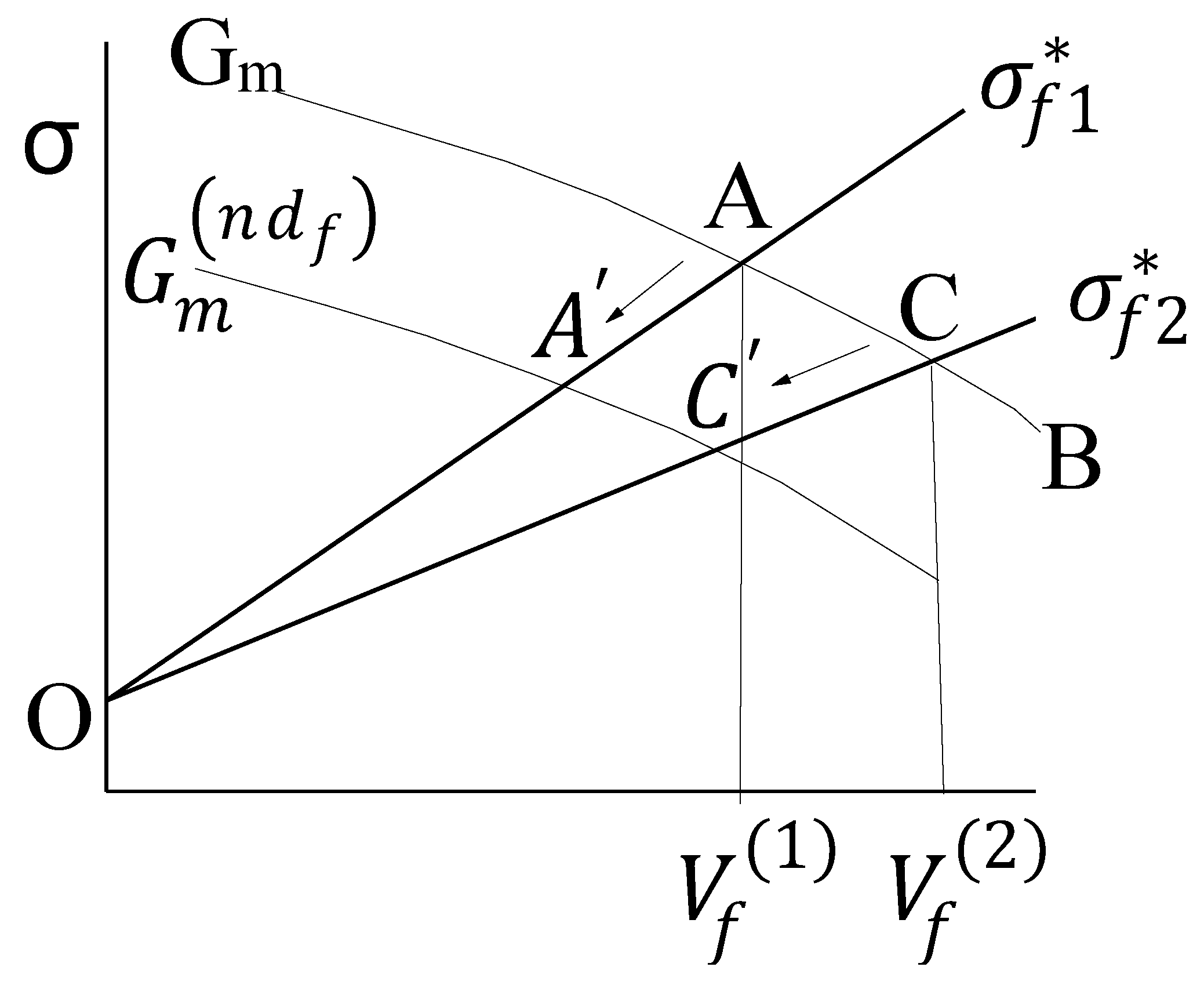
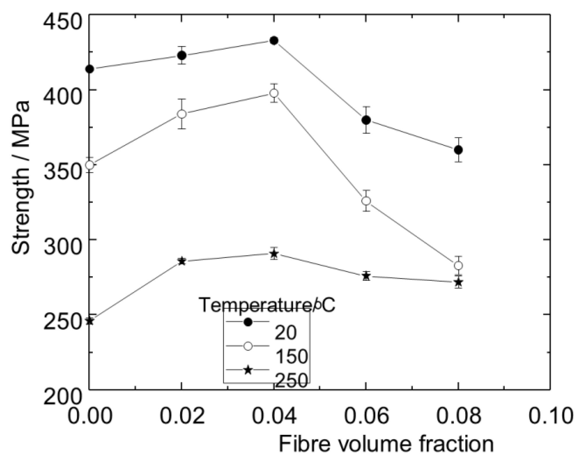
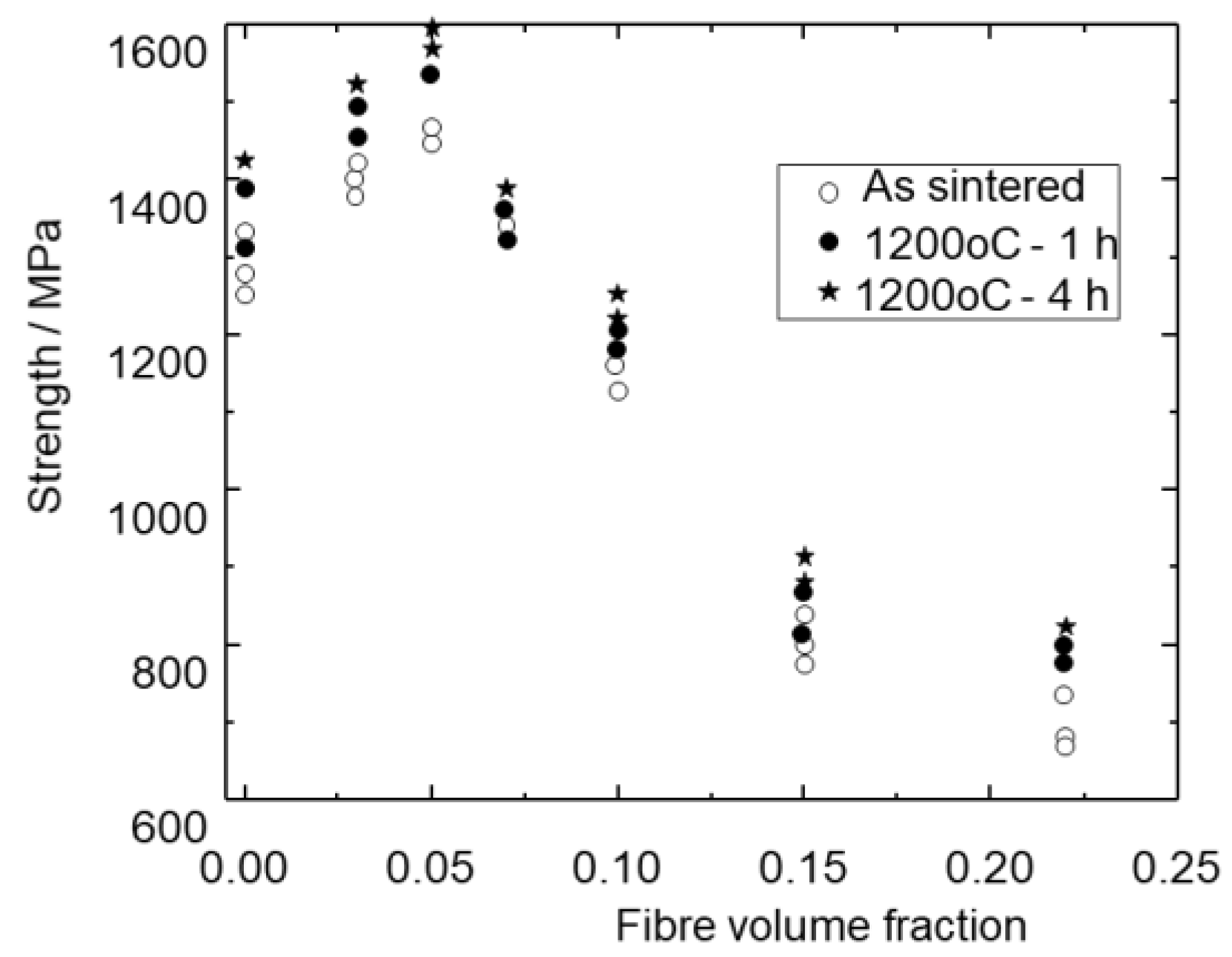
  • Non-monotone dependence of the composite strength on the fibre volume fraction is typical for MMCs. A number of the experimental results obtained in the early stage of the development of MMCs supporting this conclusion can be found in [8] (pp. 237–246, 456, 511, 576).
  • To make a composite with the highest strength, it is also necessary:
    • To use fibres of high strength on the critical length;
    • To reduce the fibre cauterization to a minimum;
    • To use a matrix of high fracture toughness.

2.2. Fracture Toughness

The most effective fibre materials are obviously brittle solids of high elastic moduli and, therefore, high values of the ideal strength. This makes the problem of composite fracture toughness an important one. The first attempt to clarify the problem was undertaken by Cooper and Kelly, who measured the critical energy release rate G of a model tungsten-fibre/copper-matrix composite [9]. They found that the value of G decreased with increasing Vf, and this was easily explained. However, the experiments performed by the present author with his colleagues [10] on boron–aluminium composites showed an increase in fracture toughness of the composites with increasing fibre volume fraction within some interval of Vf. Similar results were published in the same year by Hoover [11]. A reason for such rather unexpected results, which differ from the behaviour of the Cooper–Kelly composite, is the difference in the properties of tungsten wire and boron fibre. The strength of the brittle tungsten wires depends only slightly on the wire length; hence, they are fracturing in a macrocrack plane. Boron fibres are non-homogeneous along their length; this leads to stable multiply cracking of the fibres in a stress concentration zone in front of the macrocrack tip. An example of such microcracking is presented in Figure 2. Total energy dissipation in all plastic zones around the fibre microcracks can be larger than that in a single plastic zone in the un-reinforced matrix [12,13]. Note that an increase in the elastic modulus of a composite with an increase in Vf can also contribute to the increase in the critical stress intensity factor.
An important conclusion follows from such fracture behaviour in metal-matrix composites: a simultaneous increase in the strength and fracture toughness of MMCs makes them fundamentally different from metal alloys. This was formulated in [8] (pp. 28–29, 280–286). Later on, Ritchi wrote on “the conflicts between strength and toughness” of metal alloys [14]. This is an additional reason for replacing metal alloys with MMCs in the near future. The specific strength of MMCs, which is larger than that of the corresponding metal alloys, is an obvious reason for that.

3. Aluminium Matrix Composites

3.1. Introductory Remarks

The appearance of carbon fibre immediately attracted the attention of researches in the field of metal-matrix composites, and the first matrix material happened to be aluminium [15,16,17,18]. Study of carbon-fibre/aluminium-matrix composites became most popular in the field of CFMMCs. A comprehensive review of corresponding results obtained in the last century and in the first decade of the 21st century was given by Huang et al. [19], who did not relate the fabrication regimes and microstructures of the composites to their mechanical properties. With time, the interest in composites of such kinds has shifted from structural applications toward those in which high thermal conductivity is important. In what follows, this hypostasis of C–Al composites will be just slightly touched on, since we will be focusing on the importance of mechanical properties for structural applications of composites.
The experiments described in the papers just cited revealed the main problem of such composites: a carbon—molten aluminium interaction leads to the formation of aluminium carbide Al4C3. The carbide layer, which is full of defects, yields a decrease in the effective value of the fibre strength. The carbide layer thickness grows with time and the composite strength goes down, as shown in Figure 3, which was made using the experimental data obtained by testing carbon-fibre/pure-aluminium-matrix composites produced by pressure casting at 800 °C–36 MP–90 s, and then heat treatment at 600 °C [20]. The fibre volume fraction was 14%, and about 10% of carbon passed to the carbide after heating for 60 h.
Perhaps the most interesting data on the effect of aluminium carbide on composite strength were published by Portnoi et al. [21], who produced composites by pressure casting at temperatures from 670 to 760 °C for a time of 1 min. Changing the casting temperature led to a change in the carbide content and, consequently, in the composite strength (Figure 4). Note that the composite strength increases with the increase in carbide volume fraction from ~0.01 to ~0.03. A further carbide content increase led to a decrease in the composite strength. It can be explained by corresponding changes of the fibre–matrix interface. Aluminium melt does not wet carbon, so a short period of melt–carbon contact yields a thin carbide layer, which provides the fibre–matrix interface with strength; but a thick carbide layer full of defects causes fibre degradation and a decrease in the interface strength.
A scrupulous study of the formation of the carbide interphase in a composite with M40 carbon fibre and pure aluminium matrix was performed by the authors of Ref. [22], who produced specimens by pressure casting at 750 °C–25 MPa–10 min. They found that carbide inclusions arose on surface defects of the fibres as a result of a rapid diffusion of carbon into the melt. The growth of the carbide inclusions led to the formation of brittle bridges between neighbouring fibres. Fibre clusters reduced the composite strength.
As mentioned above, composites of such types have been developed in the last decades mainly as materials with high thermal conductivity and sufficiently high strength for non-structural applications. Typical values for these characteristics can be found in a recent paper [23]. The authors used continuous mesophase carbon fibres with a strength of 2200 MPa and a coefficient of thermal conductivity in the axial direction equal to 396 W/(m∙K) and pure aluminium as a raw material for the matrix. Composite specimens were fabricated by hot pressing at a temperature of 650 °C, which is close to the aluminium melting point. The composite micrographs revealed an amorphous substance and some quantity of the crystalline carbide. The results of measuring strength and thermal conductivity are presented in Figure 5. The composite-strength/fibre-volume-fraction dependence follows the model shown schematically in Figure 1, with a critical fibre volume fraction of about 40%. Estimation of the effective fibre strength by extrapolation of the experimental dependence σ * ( V f ) at V f < V f ( 1 ) to Vf = 1 gave the value of ~280 MPa, which was much lower than the strength of the fibre in the original state. This means that the interaction between the fibre and aluminium in the fabrication process leads to the fibre degradation. A very low thermal conductivity of the composite in the transversal direction was determined by the low thermal conductivity of the carbide coating the fibre.
Composite specimens with short fibres and a 2024 alloy matrix that were produced using powder metallurgy methods at 550 °C–30 MPa–40 min were studied in [24]. The composite specimens were tested at 20, 150, and 250 °C. Carbide inclusions on the fibre–matrix interface grew with increases in the test temperature. Shears at the interface were revealed on the fracture surface with increases in the test temperature. The composite strength maximum was observed at a fibre volume fraction of about 4% (Figure 6).
Similar results were obtained in research described in the paper [25], aimed at the development of a composite with AA7075 matrix characterized by an enhanced electric conductivity.
The formation of the carbide depends on the fibre type. An observation of the microstructures composed of the 6061 alloy matrix and fibres of low and high modulus, T700 and M40, with Young’s moduli 230 and 377 GPa, respectively, was described in [26]. In the case of the high-modulus fibre, rather small quantities of carbide crystals were grown on the fibre–matrix interface during pressure casting. On the other hand, the number of carbide inclusions was much larger in the composites with low-modulus fibres.
Composites with continuous and short fibres have been studied. Composites with short fibres are less interesting as materials for real usage because of at least two reasons. First, they are nearly isotropic; hence, they lose a very important property of fibrous composites, which can be reinforced while taking into account the future stress state of a structural element loaded by a particular external forces system. Secondly, it is very difficult to obtain a homogeneous microstructure of composites containing sufficiently high fibre volume fraction Vf in a fabrication process based on powder metallurgy methods, which lead to a maximum strength at low values of Vf. Hence, the strengthening effect is rather low.
It should also be noted that unpublished results of the experiments done about 50 years ago by A. Khvostunkov, a colleague of the present author, provided evidence of hydroscopicity of aluminium carbide. This means that high carbide content could yield a non-stability of the composite microstructure in the ambient atmosphere.
Hence, nearly all the works aimed at the development of carbon-fibre/aluminium-matrix composites have focused on either preventing or decelerating the carbide growth in the fabrication process. Three directions of the research in this field are known:
  • Coating the fibres;
  • Controlling the fibre–melt contact time;
  • Alloying the matrix with elements that form carbides more easily than aluminium.

3.2. Fibre Coatings

3.2.1. Metal Coatings

Composites with short fibres coated by nickel and Al-12Si matrix were studied in [27]. The fibre volume fractions were less than 5%. The results of the mechanical tests presented in Figure 7 show (i) a pronounced effect of the coating and (ii) the unsolved problem of getting a homogeneous fibre distribution in the matrix.
The fibre orientation in the composites does obviously affect the mechanical and thermal properties of composites with nickel-coated short fibres. An improvement of these properties can be achieved using extrusion of composite rods. It was performed by the authors of Ref. [28], who produced composites with 40% of fibres with an aspect ratio of 25 by spark plasma sintering at 500 °C–70 MPa, and then performed hot extrusion. The final result was a composite with an ultimate compression stress of 113 MPa and a thermal conductivity coefficient of 227 W/(m∙K). These values were larger than those before extrusion by 38 and 18%, respectively.
The influence of the nickel coating thickness on the mechanical properties of the composites produced at 750 °C–30 MPa–30 s was studied in [29]. The results are presented in Figure 8. It seems that a coating thickness of about 1 µm is not enough. Note that the fibre volume fraction is less than 4%.
Copper coating prevents the occurrence of aluminium carbide and provides some degree of wetting as a result of the formation of Al2Cu intermetallic on the interface [30].
In a recent paper by Chinese authors [31] who used the composite fabrication process developed earlier [32], nickel and copper coatings were obtained using an electrolytic method. An assemblage containing layers of coated fibres and pure aluminium was hot pressed in a vacuum at 670 °C–15 MPa–20 min to produce a microstructure composed of reinforced layers and aluminium ones, with thicknesses of about 50 and 200 µm, respectively. Fibre volume fraction in the reinforced layer is obviously super-critical (see Figure 1); hence, it ruptures in a brittle manner. The strength of the aluminium used in the work was 54.5 ±5.1 MPa; the strength values of the composites with fibres coated by nickel and copper were 70.4 ±4.6 MPa and 140 ± 8.7 MPa, respectively. The authors explained the difference in the strength values as better wetting of the fibres coated by copper, providing higher strength of the reinforced layer. Indeed, if we are to extrapolate the dependence of the composite strength on volume fraction VRL of the reinforced layer from VRL < 0.2 to VRL = 1, then the values of the effective strength of the reinforced layers will be 134 and 482 MPa for those with nickel- and copper-coated fibres, respectively.
The results of the experiments described in [33] provide additional confirmation of the problem of attaining homogeneous distribution of the fibre in the matrix. In this work, T700 carbon fibres with an aspect ratio of 100–150 were first chemically cleaned and then electrolytically coated by copper. The coating thickness was 0.9 µm. A slurry containing a mixture of the fibre and aluminium underwent spark plasma sintering at 550 °C–45 MPa–7 min and then annealing at 200 °C for 16 h. The strength–fibre volume fraction dependence is presented in Figure 9. It can be seen that the maximum strength value corresponds to a small fibre content.
An attempt to obtain a composite with a high thermal conductivity and sufficiently high strength by using fibres coated by chromium is also known [34]. The authors used two types of inclusions in the matrix: short carbon fibres, Vf = 0.006–0.024, as a reinforcing component, and 48% of graphite flakes with a thermal conductivity coefficient of ~1000 W/(m∙K) in the graphite plane. The fibres were coated by chromium with CTC equal to 90 W/(m∙K). No aluminium carbide was detected in the composites. The thermal and strength properties of the composites are presented in Figure 10. A decrease in thermal conductivity with increasing fibre volume fraction can be a result of an increase in chromium content.
The microstructure of the metal interphase determined by a coating method influences the composite strength via the interface strength. Hence, it is necessary to optimize the interphase. An example of such optimization of nickel interphase is presented in [35].

3.2.2. Non-Metal Coatings

A comparison of the efficiency of metallic (copper and nickel) and alumina coatings was performed in [36]. The metal coatings were produced using a traditional electrolytic method; oxide layers were applied by a sol-gel process. The coating thicknesses were 1.5 and 0.3 µm for metals and alumina, respectively. The fibres were cut into 2–3 mm lengths and used to reinforce the 6061 matrix. Composite specimens were made by casting at a temperature of 730 °C under a pressure of 7 MPa for 5 min. The observations of the composite microstructure yield rather predictable results. Thin metal coatings supplied materials to the matrix to form Al3Ni and CuAl2 compounds. They did not protect the fibre from contacts with aluminium that formed aluminium carbide. Carbide inclusions formed brittle bridges between the fibres, enhancing a percolation effect in the structure formed by the short fibres. Al2O3 coating protected the fibre from contact with molten aluminium. The shape of the fracture surface allowed the proposal that the alumina coating–matrix interface was less strong than the fibre–coating interface. The authors did not present a value of the matrix strength; they just gave the composite strength values, which were 128, 108, 114, and 144 MPa for the composites with fibres without coating and with Cu, Ni, and Al2O3 coatings, respectively.
The results of a very thorough study of composites with coated fibres are published in [37]. Fibres characterized by a strength value and Young’s modulus equal to 3500 MPa and 230 GPa, respectively, were coated by Al2O3 using a sol-gel method. The coating thickness changed from 100 to 240 nm; the fibre strength decreased nearly linearly from ~2500 to ~1900 MPa with increases in the coating thickness. Composite specimens were obtained by pressure casting (780 °C–5 MPa–3 min). The fibre volume fraction in all the specimens was 40%. The microanalysis of the specimens showed that even the thinnest coating excluded carbide formation. The strength value was the largest for the composites containing fibres with the thinnest coating (Figure 11). If we accept the fibre volume fraction to be less than the critical value V f ( 1 ) in Figure 1, then the linear extrapolation gives an effective fibre strength equal to ~585 MPa. This means that either the Vf > V f ( 1 ) and the linear extrapolation is unacceptable, or the fibre–matrix interface strength is too low to load the fibre properly. Fibre pull out seen on the fracture surfaces of the composites makes the second option more likely.
Coating fibres using a TiO2 layer of a sufficient thickness arrests the carbide formation [38]. However, it is problematical to evaluate the efficiency of this coating on the basis of the strength data presented in the paper: the fibre volume fraction in the composites obtained by pressure casting seems to be higher than the critical value ( V f ( 1 ) in Figure 1). This can explain the low value of the composite strength.
An attempt to arrest the carbide formation by CVD-coating fibres by TiN is also known [39]. However, it occurred that the layer thickness of 30–35 nm decreased the fibre strength by about 45%, and thicker layers of TiN yielded a catastrophic degradation of the fibres as a result of the formation of an interlayer composed of TiCxNy. The authors did not present any data on mechanical properties of the composites.
A melt of an Al–NaCl–KCl–K2TiF6 mixture was used to obtain a thin layer of TiC on short carbon fibres [40]. Composites with such fibres were obtained by pressure casting (800 °C–1 atm–1 h); X-ray spectra did not reveal carbide traces). Again, no mechanical properties of the specimens were presented, maybe because the fibre volume fractions in the best specimen were too large, ~57%.
Certainly, the simplest method of coating fibres using oxides was described in [41]. The authors mixed short fibres and SiO2 powder; the mixture was then heat-treated at 1433K in an argon gas atmosphere. An obtained blank was used to make C–Al composites by casting at 1073K and low pressure, 0.4 MPa, for 1 h. No carbide was seen in composites containing fibres coated by a mixture of silica and alumina formed as a result of the SiO2–Al interaction.

3.3. Controlling the Fibre–Melt Contact Time

There are known two approaches to limit the fibre–aluminium melt contact time.

3.3.1. Plasma Spraying of a Matrix Material on a Layer of Carbon Fibres

A prepreg was produced by spraying Al–6%Si alloy on a unidirectional layer of fibres [42]. Then, the laminated prepregs underwent hot pressing at a temperature between solidus and liquidus lines. The authors estimated the duration of the fibre–melt contact as less than 10 μs. They indicated the values of the strength as 180, 363, and 485 MPa for Vf = 0, 0.4, and 0.5, respectively, without disclosing the strength scatter. The result looks unexpected from the point of view of a typical strength–fibre volume fraction dependence.
This fabrication technology was further developed by the authors of [43], who used carbon yarns containing 300–700 filaments. Plasma-spraying of pure aluminium was followed by heat treatment at 350 °C for 1 h to increase the density of the composite. This method protected the composites from formation of Al4C3 inclusions, but did not yield a sufficiently dense matrix; the fracture surfaces demonstrated this clearly. The maximum composite strength reached the value of 140 MPa only.

3.3.2. Composite Wire

Another possibility for decreasing the fibre–melt contact time is pulling carbon yarn through a molten matrix material. The process was described in detail by Pippel et al. [44]. Carbon fibre–aluminium wire of a length up to 200 m with a diameter of 1.4 mm was produced by pulling a carbon yarn through a melt of pure aluminium at a temperature of 730°C. The fibre volume fraction in the wire was about 55%. It was noticed that carbide content in the composites was strongly influenced by the pulling rate (Figure 12). Essential carbide content was found even at the largest rate, corresponding to a fibre–melt contact time of less than 0.2 s. The maximum tensile strength of wire specimens of the length of 25 mm was higher than 900 MPa. Comparing this value with the fibre strength, 1800 MPa, the authors claimed that the composite strength corresponded to a “theoretical prediction”.
At this point, a question arises on the relation between the reported experimental results and the model of failure of MMCs discussed above (Figure 1), according to which the fibre volume fraction, 55%, should be larger than the critical one. However, that model is constructed for composites with an ideal fibre–matrix interface. Furthermore, in that case, plastic deformation of the matrix is the only way of dissipating the elastic energy. A thin carbide interphase between the fibre and matrix, which does not essentially affect the fibre strength but decreases the interface shear strength, provides an additional method of energy dissipation by fibre pull out. However, thickness of the interphase increasing while the fibre strength decreases leads to decreasing the composite strength.
The cavitation generated by an ultrasonic vibrator has been used to impregnate a carbon yarn with the melt from the very start of working on making composite wires [45,46]. The Japanese authors of a series of publications [47,48] studied some important features of the technology used in the ultrasonic infiltration method to produce composite wires. They found that alloying aluminium with magnesium, zinc, and bismuth affected both the vapour pressure and the surface tension of the melt and, consequently, the cavitation threshold. In particular, it was discovered that addition of the magnesium made the infiltration easier. However, the addition of more than 4.7% Mg led to the formation of brittle Al3Mg2 intermetallics that caused a decrease in the wire strength.
A possible influence of a carbon fibre type on formation of aluminium carbide was studied in [49]. Studying microstructures of wires with low- and high-modulus fibres (260 and 430 GPa) produced by using a method described in [47] led the authors to the conclusion that carbide formation on the high-modulus fibre was going on more slowly than in the case of the low-modulus fibre.
When added to an aluminium matrix, tin covers the fibre in the process of making composite wire by using acoustic cavitation, forming weak islands on the fibre–matrix interface [50]. As in the case of the thin carbide layer [21,44] this provides an additional means of energy dissipation as a result of fibre pull out. On the other hand, an increase in the critical fibre length leads to a decrease in the effective fibre strength. Hence, there is an optimal level of tin content corresponding to the maximum strength of the composite wire.
An interesting result concerning dynamical characteristics of a composite wire was reported in [51]. The data obtained by testing the wires using a modified Hopkinson rod are presented in Figure 13. The strength–strain rate dependence for the composites with T300 and M40J fibres can be explained by the corresponding dependence on the aluminium matrix. The strength values of the fibres are 2400 and 3350 MPa for T300 and M40J fibres, respectively; the corresponding values of the Young’s modulus are 230 and 360 GPa.

3.4. Alloying Matrix

The results presented in a paper published many years ago [52] do show that alloying elements changed the chemical composition of the interfaces and affected their formation. This led to a change in the fibre–matrix strength and, consequently, in the strength properties of the composites. In particular, alloying the matrix with copper reduced the composite strength; magnesium in the matrix enhanced the strength. The authors concluded that there should exist an optimal value for the magnesium content corresponding to a maximum of the composite strength. This conclusion was supported later in the experiments with composite wires (see above).
The difference in the microstructures of two composites with different aluminium alloys, 6061 (1.2%Mg) and ZL102 (9% Si), was clearly demonstrated in the experiments described in Ref. [53]. The carbide layer thicknesses in the composites produced by pressure casting (700 °C–70 MPa–100 s) followed by the extrusion at 620 °C were ~0.15 and 0.4 µm, respectively.

3.5. Carbon-Fibre/Aluminium-Matrix Composites: State of the Art and Prospects

(1)
The results obtained in the 21st century did not lead to the emergence of new technological ideas to make C–Al composites as compared to those born in the previous decades and reviewed in [19]. Hence, the present author is focusing on the strength of the composites, as that is the main property of a structural material. It is important to note that most of the fabrication methods for such composites are based on liquid phase processes.
(2)
The liquid phase processes do not allow the use of alloys of sufficiently high fracture toughness for the matrix. This limits the values of strength and fracture toughness for the composites.
(3)
Short-fibre composites obtained through powder metallurgy methods reach maximum strength values with small fibre volume fractures, which makes them ineffective structural materials.
(4)
The small diameter of carbon filaments requires liquid phase fabrication methods that bring the problems formulated above. On the other hand, the small filament diameter corresponds to a small microcrack size, occurring as a result of filament breaks. This can shift the critical fibre volume fraction to higher values, as compared with the case of a larger fibre diameter.
(5)
Despite the long history of C–Al composites development, just one use of such composites has been described [54]. The widespread usage of C–Al composites in highly loaded structures will be possible, provided new ideas of making them are generated.

4. Titanium Matrix Composites

The usage of solid phase technological processes to reinforce a titanium matrix with continuous carbon fibres is certainly impossible due to the small diameter of filaments. The electrolytic process can hardly be used to produce sufficiently large structural elements since the process rate is too low. A direct usage of liquid phase technologies would lead to degradation of the fibres as a result of the formation of titanium carbide. Hence, some researchers, including the present author, used powder metallurgy methods to make short fibre composites. We start with the results of these works and then proceed with composites containing continuous fibres obtained by a special method based on liquid phase technology.

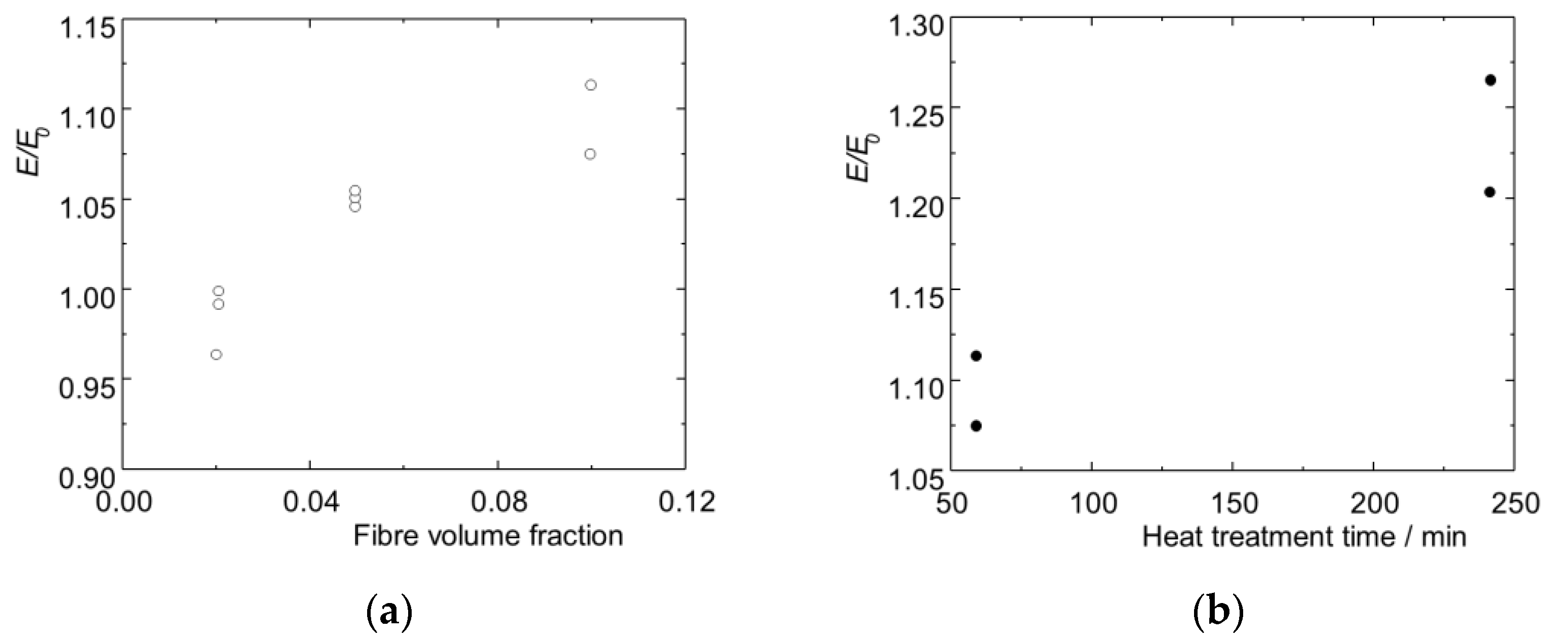
4.1. Short Fibre Composites

Perhaps the first experiments aimed at obtaining such composites were reported in a brief communication [55]. The composite specimens were made by blending the fibre–matrix mixture in a ball mill, followed by cold pressing and sintering at a temperature of 850 °C for 60 min. Finally, the specimens underwent heat treatments. It is interesting to note that no titanium carbide was seen after sintering. The carbide was detected by x-ray analysis only after the heat treatment at 880 °C (Figure 14a). The results obtained in Ref. [56] a quarter of the century later (Figure 14b) differ from those obtained in [55]. Note that the carbide layer thickness in [55] was calculated via composite density, whereas it was measured on micrographs of the composite cross-sections in [56]. Certainly, the data presented in Figure 14b are more precise.
Blending a fibre–matrix mixture homogenized the blend, leading to an increase in the composite strength. On the other hand, this caused fracturing of the fibres, which yielded a decrease in the strength. Such a procedure led to a non-monotonic dependence of the composite strength on the fibre volume fraction. The composite strength reached a maximum value at a relatively low fibre volume fraction [55,57]. The results are presented in Figure 15 and Figure 16.
The formation of titanium carbide during heat treatments led to an increase in the Young’s modulus of the composites, Figure 17 [55].
The results obtained by studying titanium matrix composites with short carbon fibres show that such composites can replace titanium alloys in some applications, but this will not lead to an essential improvement in the mechanical behaviour of the structural elements, because the existing fabrication technologies do not allow increasing fibre volume fraction to really be useful for the composites. A relatively small increase in the composite strength was determined as compared to that of the matrix.

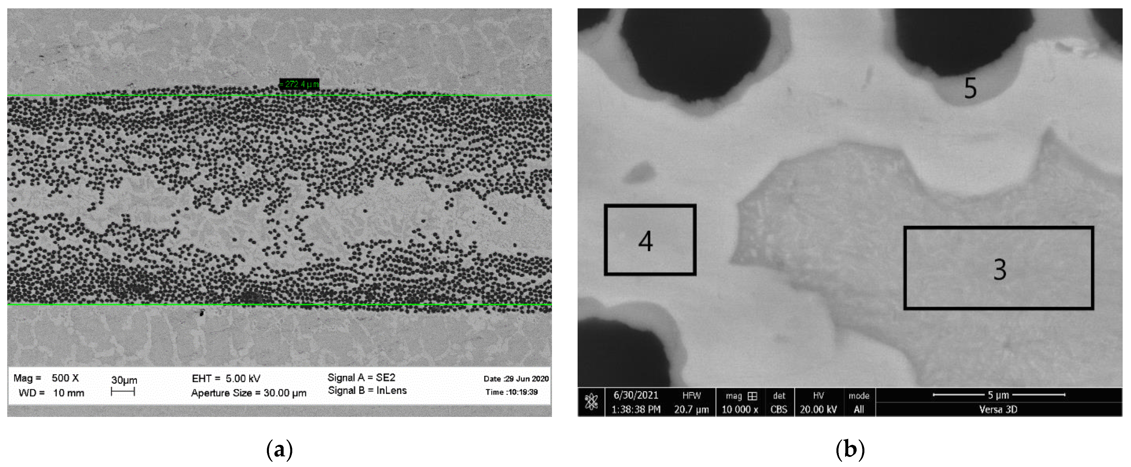
4.2. Continuous Fibre Composites

A technological scheme based on a liquid phase impregnation of a carbon-fibre fabric was suggested by Mileiko et al. [58]. The fabric, made of low-modulus carbon fibre located between titanium foil, was infiltrated by an intermediate matrix of a relatively low melting point. A Ti–Ti5Si3 eutectic with a melting point of ~1330 °C was chosen as the intermediate matrix, wetting a particular fibre used in the experiments. A specimen with a length of about 100 mm was infiltrated with the intermediate matrix melt for about 1 s, and then was immediately moved to a cold zone of the furnace. So, the thickness of the titanium carbide layer around a filament in the microstructure was just about 1 µm.
At a temperature of 600°C, the specific strength and creep resistance values of composites characterized by sufficiently high fracture toughness make the composites attractive materials. However, a technological scheme developed many years ago does not allow for the making of structural elements. Moreover, the possibility of transforming this scheme into fabrication technology is not visible, since the temperature/time condition of the fibre–melt contact cannot be controlled with the necessary precision.
The novel technological scheme developed recently [59,60,61] is free from the drawbacks of the old one. First of all, in the new scheme, wetting the fibre with the intermediate matrix is not necessary. Secondly, the temperature/time conditions of the fibre–melt contact can be controlled. Finally, the possibility of producing sufficiently large structural elements is visible. The scheme presented in Figure 18 makes these features clear.
At the same time, it is clear that the fabrication process that forms a hierarchical composite microstructure presented in Figure 19 is characterized by a much larger number of parameters than traditional metal-matrix composites. The most important parameters are as follows:
(1)
The strength and Young’s modulus of the fibre.
(2)
The content of the reinforcing layer (RL), composed of the fibre, titanium carbide, and intermediate matrix.
(3)
The fibre volume fraction in the reinforcing layer.
(4)
The thickness of the reinforcing layer hRL.
(5)
The intermediate matrix composition.
(6)
The thickness of the carbide layer.
(7)
The strength of the C–TiC–intermediate matrix–main matrix interfaces.
Figure 19. SEM microphotographs of the cross-section of cabon-fibre (a)/titanium-matrix compo-sites (b).
Jcs 06 00297 g019
The experimental series described in [61] was not aimed at obtaining dependencies of mechanical properties of the composites on all the parameters mentioned. At first, it was important to understand the influence of a particular fabrication process on the mechanical behaviour of the composites of a new type. The fibres produced by UMATEX (Table 1) were used in the experiments. The main matrix was pure titanium, a typical load–displacement curve of which—after being heated at the temperature of the fabrication process of the composites—is presented in Figure 20. A mixture of titanium and nickel powders in the weight ratio of 72:28, corresponding to the Ti–Ti2Ni eutectic, with the melt point of ~950 °C was used as the intermediate matrix precursor. The precursor was introduced to the specimen as a slurry layer of a thickness of 0.2–1 mm, corresponding to the average metal powder content of 0.20–1.03 mg/mm2. The composite specimens had four and eight reinforcing layers containing UMT49-12K-EP and UMT40-3K-EP fibres, respectively.
A detailed description of the composite microstructures and the results of the mechanical testing of composite specimens can be found in [61]. Here, we just present generalized data on the mechanical behaviour of the composites produced through various fabrication regimes.
Elastic characteristics of the composites are obviously given by a linear combination of the elastic moduli of the components. Hence, they can easily be calculated, provided that the volume fractions of the components are known. An analysis of the composite microstructures gives the volume fractions of the main titanium matrix and the reinforcing layer composed of carbon fibres, titanium carbide, and intermediate matrix. The experimental data obtained through 3-points bending and the results of the calculation of the Young’s modulus E in tension are presented in Figure 21a. The experimental values of E for the composites with UMT40 fibres were slightly lower than the calculated values for tension. This can be explained by the relatively low shear strength of the composite specimens tested in bending. On the contrary, the average experimental value of the Young’s modulus of the composites with UMT40 fibres, 157 GPa, was nearly equal to the calculated value. This means that the input data in the calculation were not sufficiently precise.
It is more important to compare specific values E / γ of the Young’s modulus of the composites to that of titanium, E T i / γ T i . This is performed in Figure 21b, where some calculated data for the composites with high-modulus fibres UMT530-12K (Ef = 530 GPa, TEX = 680, γ = 1.93 g/cm3) are added to the data for the composites tested. The specific values of the Young’s modulus of the composites studied can be higher than that of titanium by nearly two times. This ratio can be more than two, provided high-modulus fibres are used. It is important to note that the anisotropy of the composites’ elastic properties is low, as the Young’s modulus in the transverse direction is expected to be slightly higher than that of the titanium matrix.
A quantitative analysis of the strength–reinforcement layer fraction dependence of the composite is to be based on the failure model for such type composites, characterized by a complicated microstructure with a large number of structural parameters. Such a model has not been constructed yet. So now it remains to interpret experimental data qualitatively, bearing in mind the failure model of MMCs with the traditional microstructure presented in Section 2.
All the experimental data obtained by testing composite specimens produced through various technological regimes (1040–1050 °C, 0.08–0.52 MPa, and an infiltration time of 0.5–5 min), and with various slurry layer thicknesses, are presented in Figure 22. Here, the volume fraction V R L = N h R L / H , where N is the number of reinforcing layers, and hRL and H are the thicknesses of RL and a specimen, respectively. Note that the average values of hRL are 0.275 and 0.075 mm for specimens with UMT49 and UMT40, respectively.
One can see that:
(1)
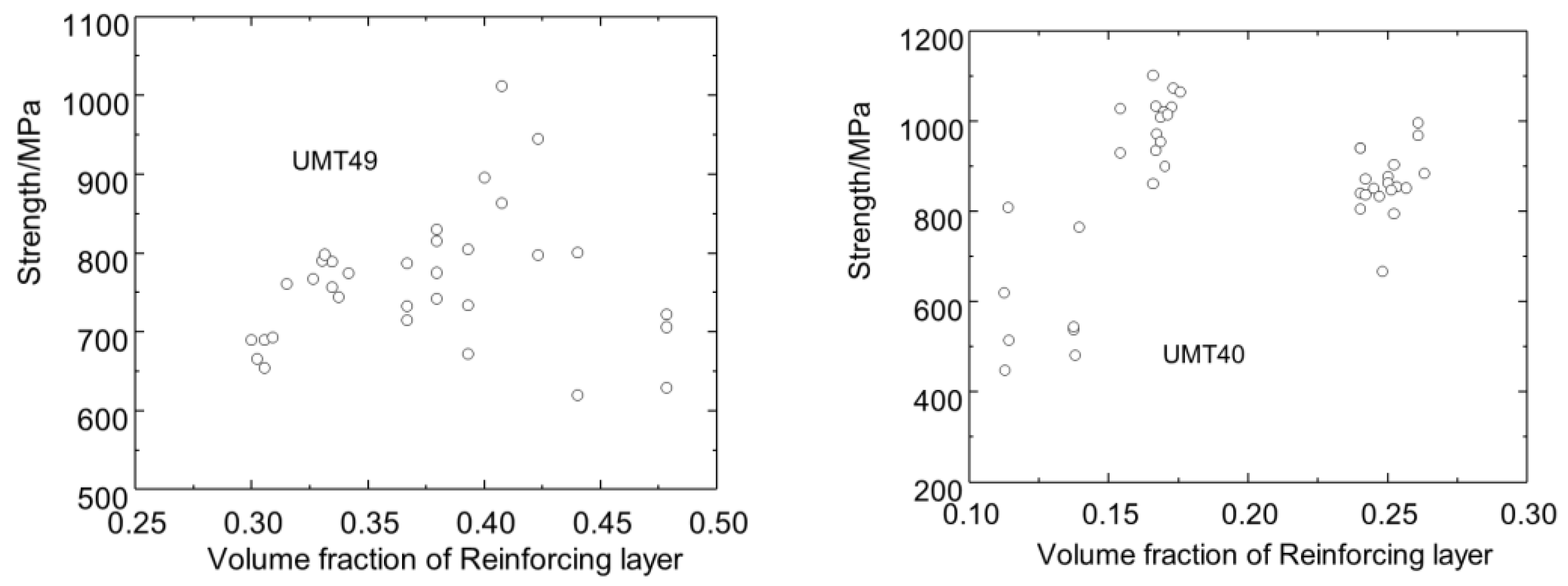
Qualitatively, the dependence of the composite strength on the reinforcing layer volume fraction is similar to the dependence of the fibrous composite strength on the fibre volume fraction shown schematically in Figure 1.
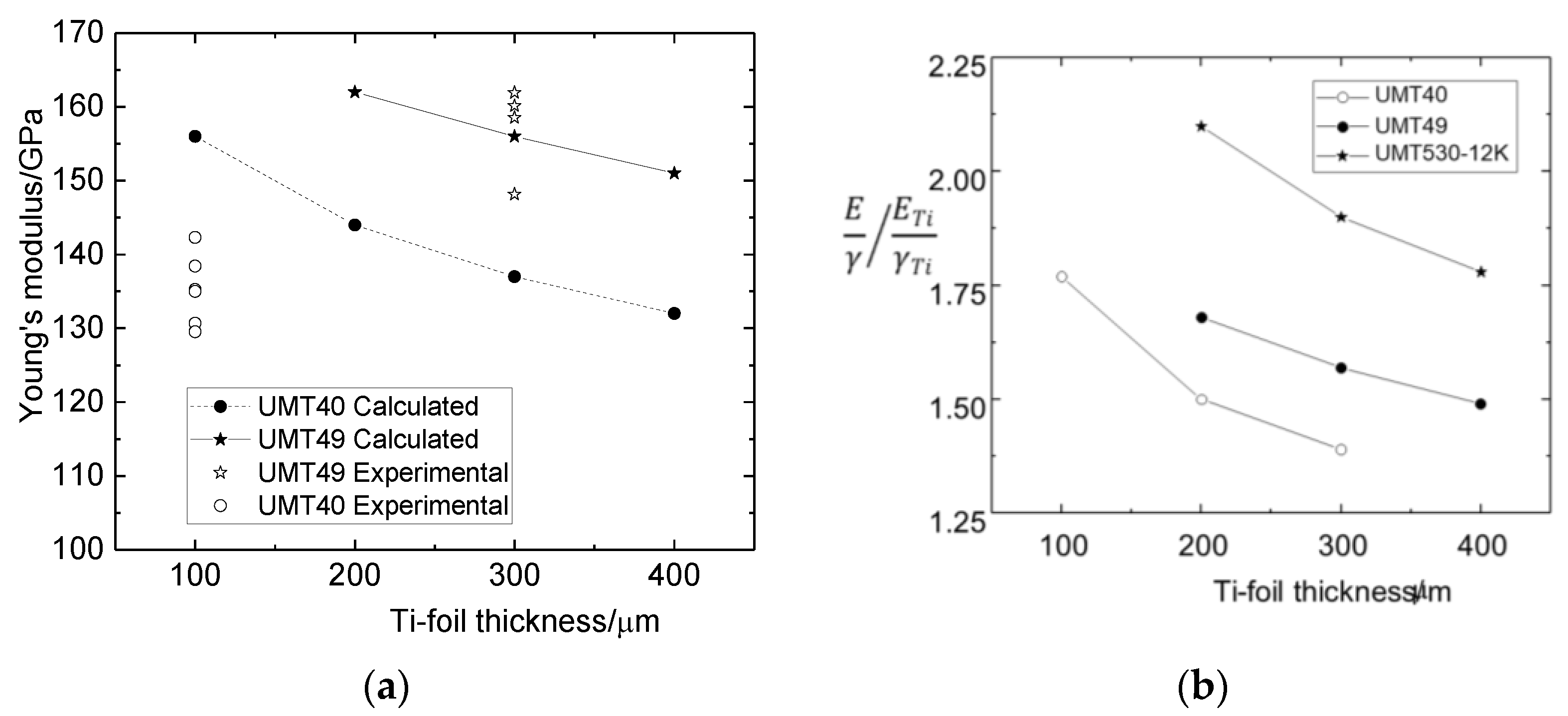
(2)
The maximum strength of the composites with UMT40 fibres is higher than that of the composites with UMT49 fibres because the effective strength of the thinner reinforcing layer with UMT40 fibres is much higher than that of the layer containing UMT49 fibres. This can be easily explained by the strength scale effect of the reinforcing layers.
(3)
The critical volume fraction of the reinforcing layer with UMT40 fibres is much smaller than that of the layer with UMT49 fibres. This is a result of what was said just above. The similarity between the behaviour of traditional MMCs with effective values of the fibre strength σ f 2 *   and   σ f 1 * is obvious.
(4)
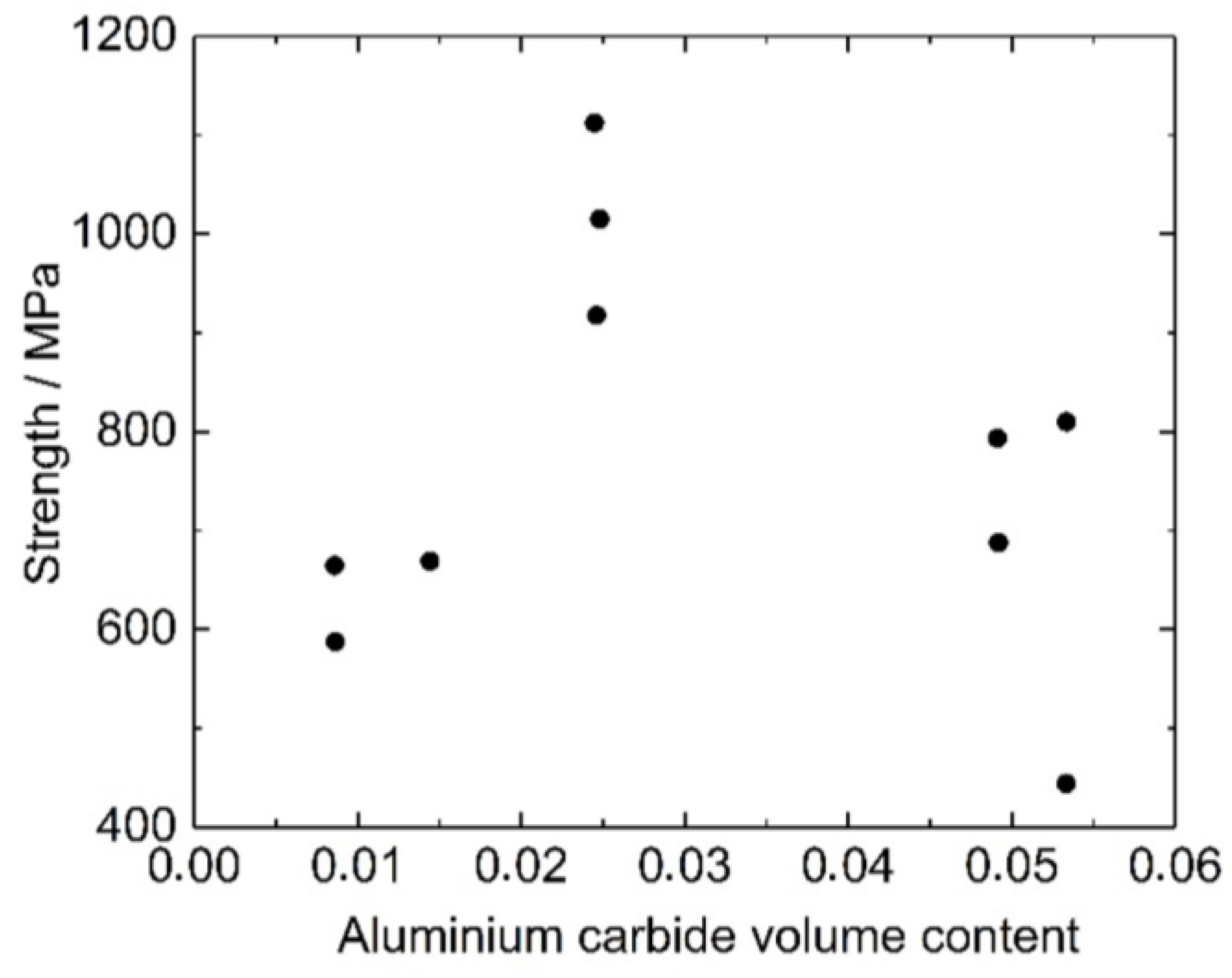
A large scatter of the experimental points is explained by plotting all the data obtained through various technological regimes. Still, the strength maximum can be seen clearly.

4.3. Carbon-Fibre/Titanium-Matrix Composites: State of the Art and Prospects

Titanium matrix composites with continuous carbon fibres became real materials very recently. Still, the preliminary study of the new technological scheme of making carbon fibre–titanium matrix composites by using an intermediate matrix of a melting point lower than that of titanium gives hope that they can effectively replace titanium and aluminium alloys in structural elements, in which CFRPs cannot be used.

5. Nickel Matrix Composites

The first attempts to reinforce nickel matrix using carbon fibres started a long time ago [62,63,64]. The data on the stability of the fibre in nickel matrix, published before the mid-1990s and discussed in [8] (p. 466), are rather contradictory. Still, most of the experiments indicated the limiting stability conditions as 800 °C–1 h. With time, the interest in this research topic started disappearing, certainly because of the absence of new technological ideas. Note that in the paper published 5 years ago [65], only the papers already mentioned 25 years before in [8] were reviewed.
Very recently, the interest in C–Ni composites resumed on the basis of creating a nano-crystalline matrix by an electroless process [66]. It was shown that the composite strength depended on the matrix grain size. The maximum values of the composite strength at temperatures of 20 and 200 °C were ~1475 and 1250 MPa, respectively. The matrix grain size for the strength maximum was 80 nm. This effect related to the maximum of the matrix strength at its grain size of 80 nm. The composite strength at 400°C did not depend on the matrix grain size in the 40–200 nm interval and was about 750 MPa.
It should be noted that:
(a)
The fibre–matrix interface strength depended slightly on the matrix grain size, and its value was about 35 MPa. This means that the critical length of the fibre is rather large and the effective fibre strength cannot be sufficiently high.
(b)
The maximum strength of the composites at room temperature, ~1475 MPa, was just a bit higher than that of the matrix, 1238 MPa. This may be so because the fibre volume fraction, 40%, is supercritical.
(c)
The composite strength decreased rapidly as the temperature rose from 200 to 400 °C.
Powder metallurgy methods for producing C–Ni composites are ineffective, as they are in the case of C–Ti composites. Experimental results obtained in [67] show it clearly. The composite billets were produced by mixing carbon fibres of a length of 1–2 mm, which were coated by copper and nickel powder. The mixture was then cold pressed at 300 MPa and underwent sintering at 1200 °C for 1 h in an argon gas atmosphere. The tensile strength of the composite increased from ~260 MPa of the matrix to about 320 MPa at Vf = 0.05, but then decreased to the matrix strength at Vf = 0.10. Heating the composites at 1200 °C for 40 h did not change the type of the strength–fibre volume fraction dependence, but the composite strength values decreased. The use of 20Cr–80Ni alloy as the matrix did not enhance the composite strength.
Scarce information on nickel matrix composites does not allow for evaluating their prospects.

6. Main Conclusions

  • Carbon-fibre/metal-matrix composites (CFMMCs) will definitely replace metal alloys in applications for which specific values of mechanical properties are of importance.
  • Powder metallurgy methods for producing CFMMCs are not effective because of at least two reasons. First, the strength maximum values are achieved at low fibre volume fractions. Secondly, such methods do not allow for designing composites according to the future stress state of a structural element.
  • Liquid phase fabrication technologies applied to CFMMCs require either special fibre coatings to prevent carbon–metal chemical interactions or special methods, which provide either an essential decrease in the fibre–liquid metal contact, as has been performed in the case of C/Al composite wire, or a decrease in the melt temperature, as in the case of C/Ti composites. The C–Al wire cannot be used directly as a structural material. The C/Ti composites produced by using an intermediate matrix with a low melt temperature are just at an early phase of development.
  • Anyway, to bring the time of the real usage of carbon fibre–metal matrix composites closer, it is necessary to look for new ideas of making them.

Funding

This research was performed within the frameworks of the state assignment to Osipyan Institute of Solid State Physics of Russian Academy of Sciences.

Acknowledgments

The help of Nelly Prokopenko in preparing the manuscript and Catherine Sarkisyan-Mileiko in improving English is acknowledged.

Conflicts of Interest

The author declares no conflict of interest.

References

  1. Kelly, A.; Tyson, W.R. Tensile properties of fibre-reinforced metals: Copper/tungsten and copper/molybdenum. J. Mech. Phys. Solids 1965, 13, 329–350. [Google Scholar] [CrossRef]
  2. Kelly, A.; Tyson, W.R. Tensile properties of fibre reinforced metals-II Creep of silver-tungsten. J. Mech. Phys. Solids 1966, 14, 177–184. [Google Scholar] [CrossRef]
  3. Mileiko, S.T. The tensile strength and ductility of continuous fibre composites. J. Mater. Sci. 1969, 4, 974–977. [Google Scholar] [CrossRef]
  4. Aveston, J.; Kelly, A. Theory of multiply fracture of fibrous composites. J. Mater. Sci. 1973, 8, 352–362. [Google Scholar] [CrossRef]
  5. Naslain, R. SiC/SiC Composites: Thermostructural Materials for Applications in Severe Environments; Peking University Press: Beijing, China, 1996; pp. 37–52. [Google Scholar]
  6. Mileiko, S.T.; Sarkissyan, N.S.; Kolchin, A.A.; Kiiko, V.M. Oxide fibres in a Ni-based matrix—Do they degrade or become stronger? Proc. Inst. Mech. Eng. Part L J. Mater. Des. Appl. 2004, 218, 193–200. [Google Scholar]
  7. Mileiko, S.T.; Sarkissyan, N.S.; Serebryakov, A.V.; Trifonov, S.V. Structure and properties of boron-aluminium composites. Compos. Sci. Technol. 1994, 50, 423–430. [Google Scholar] [CrossRef]
  8. Mileiko, S.T. Metal and Ceramic Based Composites; Elsevier: Amsterdam, The Netherlands, 1997. [Google Scholar]
  9. Cooper, G.A.; Kelly, A. Tensile properties of fibre-reinforced metals: Fracture mechanics. J. Mech. Phys. Solids 1967, 15, 279–297. [Google Scholar] [CrossRef]
  10. Mileiko, S.T.; Sorokin, N.M.; Zirlin, A.M. Crack propagation in a boron/aluminium composite. Mech. Compos. Mater. 1976, 6, 1010–1017. (In Russian) [Google Scholar]
  11. Hoover, W.R. Crack initiation in B-Al composites. J. Compos. Mater. 1976, 10, 106–117. [Google Scholar] [CrossRef]
  12. Mileiko, S.T.; Suleimanov, F.K. A moldel of macrocrack in a composite. Mech. Compos. Mater. 1981, 3, 421–425. (In Russian) [Google Scholar]
  13. Mileiko, S.T. Fracture-toughness/notch-sensitivity correlation for metal-and ceramic-based fibrous composites. Compos. Part B-Eng. 2017, 116, 1–6. [Google Scholar] [CrossRef]
  14. Ritchie, R.O. The conflicts between strength and toughness. Nat. Mater. 2011, 10, 817–822. [Google Scholar] [CrossRef] [PubMed]
  15. Baker, A.A.; Martin, A.; Bache, R.J. Carbon-fibre metal-matrix composites: Fabrication by electrodeposition. Composites 1971, 2, 154–160. [Google Scholar] [CrossRef]
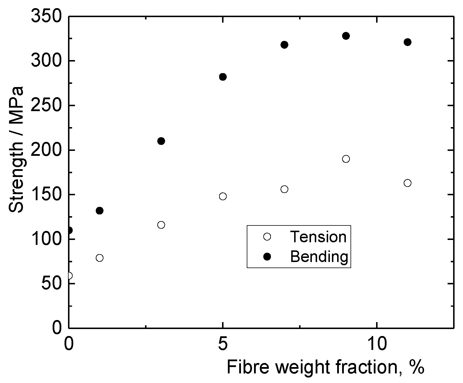
  16. Jackson, P.W.; Braddick, D.M.; Walker, P.J. Tensile and flexural properties of carbon fibre-aluminium matrix composites. Fibre Sci. Technol. 1972, 5, 219–236. [Google Scholar] [CrossRef]
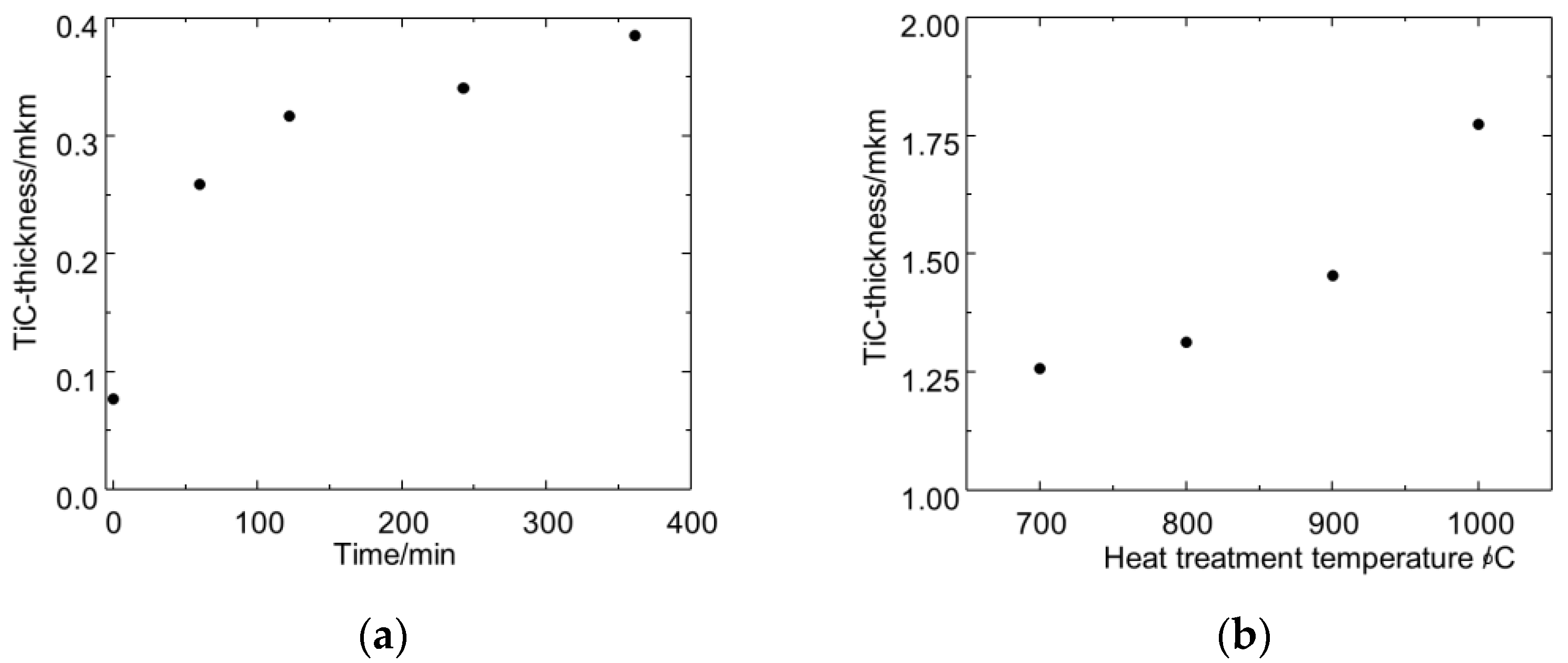
  17. Okura, A.; Motoki, K. Rate of formation of intermetallic compounds in aluminium matrix-carbon fibre composites. Compos. Sci. Technol. 1985, 24, 243–252. [Google Scholar] [CrossRef]
  18. Islam, M.U.; Wallace, W. Carbon fibre reinforced aluminium matrix composites: A critical review. Mater. Manuf. Process. 1988, 3, 1–35. [Google Scholar] [CrossRef]
  19. Huang, Y.; Ouyang, Q.; Zhang, D.; Zhu, J.; Li, R.; Yu, H. Carbon materials reinforced aluminium composites: A review. Acta Metall. Sin. (Engl. Lett.) 2014, 27, 775–786. [Google Scholar] [CrossRef] [Green Version]
  20. Li, S.-H.; Chao, C.-G. Effects of carbon fiber/Al interface on mechanical properties of carbon-fiber-reinforced aluminium-matrix composites. Metall. Mater. Trans. A 2004, 35A, 2153–2160. [Google Scholar] [CrossRef]
  21. Portnoi, K.I.; Timofeeva, N.I.; Zabolotskii, A.A.; Sakovich, V.N.; Trefilov, B.F.; Levinskaya MKh Polyak, N.N. Dependence of the properties of a carbon –aluminium composite material on its carbide phase content. Sov. Powder Metall. 1981, 20, 116–119. [Google Scholar] [CrossRef]
  22. Xu, W.; Wang, C.; Zhang, Z.; Liang, P.; Shi, Y.; Zhang, G. Interfacial microstructure and growth mechanism of Al4C3in Grf/Al composites fabricated by liquid pressure method. Micron 2014, 65, 10–14. [Google Scholar] [CrossRef]
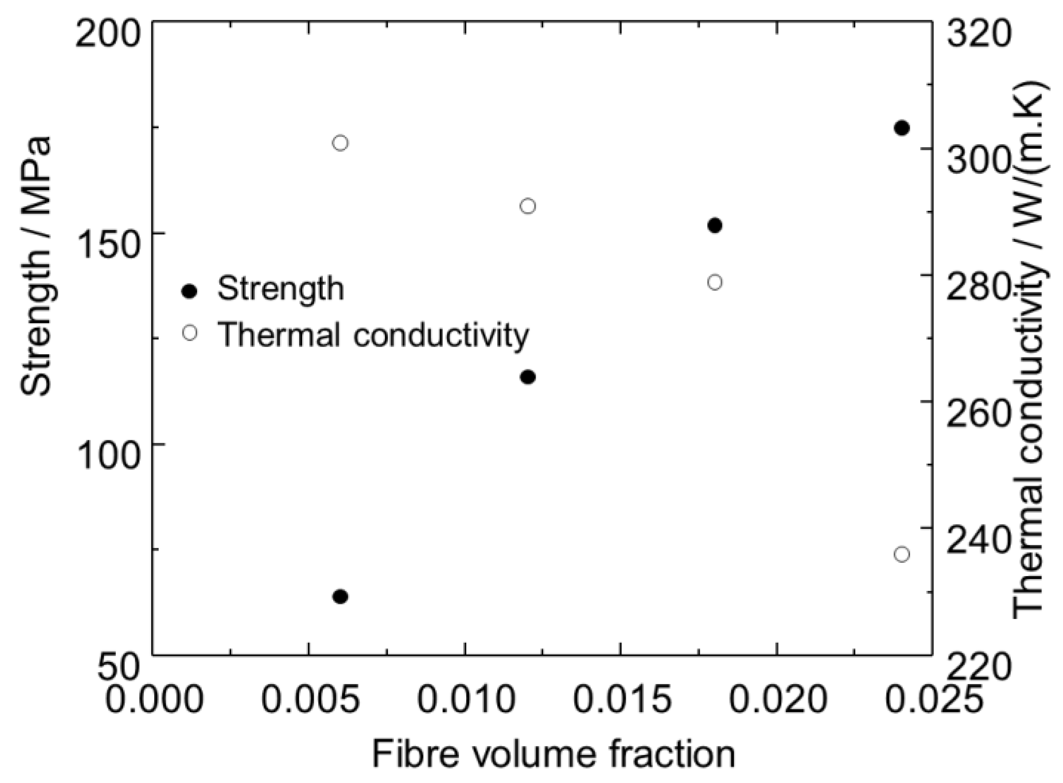
  23. Zhu, C.; Su, Y.; Wang, X.; Sun, H.; Ouyang, Q.; Zhang, D. Process optimization, microstructure characterization and thermal properties of mesophase pitch-based carbon fiber reinforced aluminium matrix composites fabricated by vacuum hot pressing. Compos. Part B-Eng. 2021, 215, 108746. [Google Scholar] [CrossRef]
  24. Zhang, C.; Wu, J.; Meng, Q.; Sun, Y.; Wen, Y. The evolution of interfacial microstructure and fracture behavior of short carbon fiber reinforced 2024 Al composites at high temperature. Appl. Sci. 2019, 9, 3477. [Google Scholar] [CrossRef] [Green Version]
  25. Deshpandea, M.; Gondil, R.; Waikar, R.; Murty, S.V.S.N.; Mahat, T.S. Processing and characterization of carbon fiber reinforced aluminium 7075. Mater. Today-Proc. 2018, 5, 7115–7122. [Google Scholar] [CrossRef]
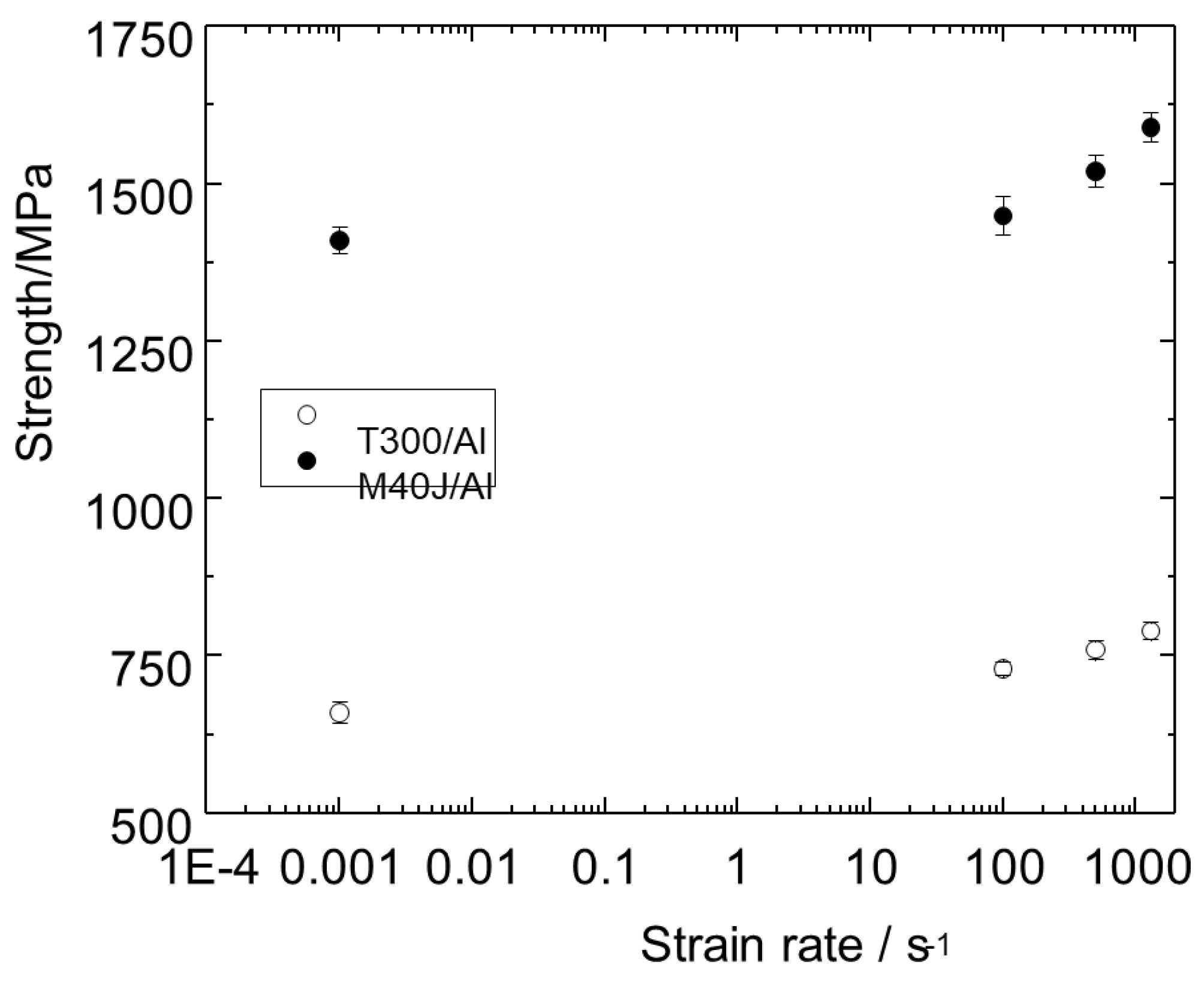
  26. Zhang, Y.; Wu, G. Comparative study on the interface and mechanical properties of T700/Al and M40/Al composites. Rare Metals 2010, 29, 102–107. [Google Scholar] [CrossRef]
  27. Baghi, M.; Niroumand, B.; Emadi, R. Fabrication and characterization of squeeze cast A413-CSF composites. J. Alloy Compd. 2017, 710, 29–36. [Google Scholar] [CrossRef]
  28. Yi, L.-F.; Yamamoto, T.; Onda, T.; Chen, Z.-C. Orientation control of carbon fibers and enhanced thermal/mechanical properties of hot-extruded carbon fibers/aluminium composites. Diam. Relat. Mater. 2021, 116, 108432. [Google Scholar] [CrossRef]
  29. Alten, A.; Erzi, E.; Gürsoy, O.; Hapçı, G.; Agaglu, A.; Dispinar, D.; Orhan, G. Production and mechanical characterization of Ni-coated carbon fibers reinforced Al-6063 alloy matrix composites. J. Alloy Compd. 2019, 787, 543–550. [Google Scholar] [CrossRef]
  30. Ureña, A.; Rams, J.; Escalera, M.D.; Sánchez, M. Effect of copper electroless coatings on the interaction between a molten Al–Si–Mg alloy and coated short carbon fibres. Compos. Part A Appl. Sci. Manuf. 2007, 38, 1947–1956. [Google Scholar] [CrossRef]
  31. Sha, J.-J.; Lü, Z.-Z.; Sha, R.-Y.; Zu, Y.-F.; Dai, J.-X.; Xian, Y.-Q.; Zhang, W.; Cui, D.; Yan, C.-L. Improved wettability and mechanical properties of metal coated carbon fiber-reinforced aluminium matrix composites by squeeze melt infiltration technique. Trans. Nonferrous Met. Soc. China 2021, 31, 317–330. [Google Scholar] [CrossRef]
  32. Hua, Z.; Liu, Y.; Yao, G.; Wang, L.; Ma, J.; Liang, L. Preparation and characterization of nickel-coated carbon fibers by electroplating. J. Mater. Eng. Perform. 2012, 21, 324–330. [Google Scholar] [CrossRef]
  33. Gao, M.; Gao, P.; Wang, Y.; Lei, T.; Ouyang, C. Study on metallurgically prepared copper-coated carbon fibers reinforced aluminium matrix composites. Met. Mater. Int. 2021, 27, 5425–5435. [Google Scholar] [CrossRef]
  34. Peng, X.; Huang, Y.; Sun, X.; Han, X.; Fan, R. Effect of chromium coated carbon fiber on the thermal and mechanical properties of Cr@Gf/Cr@CF/Al composites. J. Mater. Sci. Mater. Electron. 2019, 30, 7226–7233. [Google Scholar] [CrossRef]
  35. Liu, J.; Zhang, Y.; Guo, Z.; Liu, S.; Zhang, J.; Jie, J.; Fu, Y.; Li, T. Enhancement of fiber–matrix adhesion in carbon fiber reinforced Al-matrix composites with an optimized electroless plating process. Compos. Part A Appl. Sci. Manuf. 2021, 142, 106258. [Google Scholar] [CrossRef]
  36. Tang, Y.; Liu, L.; Li, W.; Shen, B.; Hu, W. Interface characteristics and mechanical properties of short carbon fibers/Al composites with different coatings. Appl. Surf. Sci. 2009, 255, 4393–4400. [Google Scholar] [CrossRef]
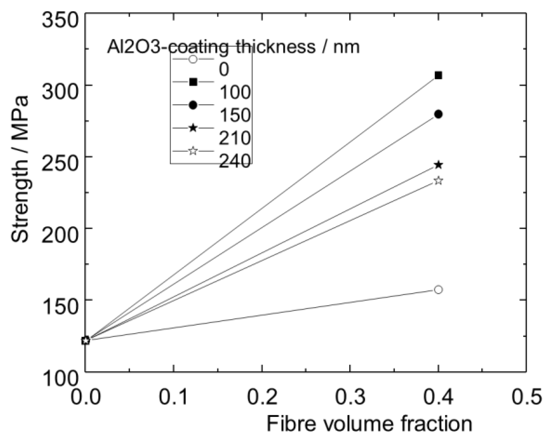
  37. Zhu, C.; Su, Y.; Zhang, D.; Ouyang, Q. Effect of Al2O3 coating thickness on microstructural characterization and mechanical properties of continuous carbon fiber reinforced aluminium matrix composites. Mater. Sci. Eng. A 2020, 793, 139839. [Google Scholar] [CrossRef]
  38. Soloviev, P.V.; Gallyamova, R.F.; Gomzin, A.I. The influence of barrier coating parameters on the strength of metal matrix composites. Lett. Mater. 2019, 9, 360–365. [Google Scholar] [CrossRef]
  39. Abidin, A.Z.; Kozera, R.; Höhn, M.; Endler, I.; Knaut, M.; Boczkowska, A.; Czulak, A.; Malczyk, P.; Sobczak, N.; Michaelis, A. Preparation and characterization of CVD-TiN-coated carbon fibers for applications in metal matrix composites. Thin Solid Film. 2015, 589, 479–486. [Google Scholar] [CrossRef]
  40. Baumli, P.; Sychev, J.; Budai, I.; Szabo, J.T.; Kaptay, G. Fabrication of carbon fiber reinforced aluminium matrix composites via a titanium-ion containing flux. Compos. Part A Appl. Sci. Manuf. 2013, 44, 47–50. [Google Scholar] [CrossRef]
  41. Meng, X.; Choi, Y.; Matsug, K.; Hu, W.; Liu, W. Development of short carbon fiber reinforced aluminium matrix composites by low pressure infiltration process. IOP Conf. Ser. Mater. Sci. Eng. 2019, 547, 012024. [Google Scholar] [CrossRef]
  42. Silber, M.; Wenzelburger, M.; Gadow, R. New manufacturing process for thermally sprayed prepregs with local UD fiber reinforcement for semi-solid forming of light metal MMC. Int. J. Mater. Form. 2009, 2, 745–748. [Google Scholar] [CrossRef]
  43. Xiong, J.-T.; Zhang, H.; Peng, Y.; Li, J.-L.; Zhang, F.-S. Fabrication and characterization of plasma-sprayed carbon-fiber-reinforced aluminium composites. J. Therm. Spray Technol. 2018, 27, 727–735. [Google Scholar] [CrossRef]
  44. Pippel, E.; Woltersdorf, J.; Doktor, M.; Blucher, J.; Degischer, H.P. Interlayer structure of carbon fibre reinforced aluminium wires. J. Mater. Sci. 2000, 35, 2279–2289. [Google Scholar] [CrossRef]
  45. Cheng, H.M.; Lin, Z.H.; Zhou, B.L.; Zhen, Z.G.; Kobayashi, K.; Uchiyama, Y. Preparation of carbon fibre reinforced aluminium via ultrasonic liquid infiltration technique. Mater. Sci. Technol. 1993, 9, 609–614. [Google Scholar] [CrossRef]
  46. Deming, Y.; Xinfang, Y.; Jin, P. Continuous yarn fibre-reinforced aluminium composites prepared by the ultrasonic liquid infiltration method. J. Mater. Sci. Lett. 1993, 12, 252–253. [Google Scholar] [CrossRef]
  47. Matsunaga, T.; Ogata, K.; Hatayama, T.; Shinozaki, K.; Yoshida, M. Effect of acoustic cavitation on ease of infiltration of molten aluminium alloys into carbon fiber bundles using ultrasonic infiltration method. Compos. Part A 2007, 38, 771–778. [Google Scholar] [CrossRef]
  48. Matsunaga, T.; Matsuda, K.; Hatayama, T.; Shinozaki, K.; Yoshida, M. Fabrication of continuous carbon fiber-reinforced aluminium–magnesium alloy composite wires using ultrasonic infiltration method. Compos. Part A 2007, 38, 1902–1911. [Google Scholar] [CrossRef]
  49. Galyshev, S.; Gomzin, A.; Gallyamova, R.; Khodos, I.; Musin, F. On the liquid-phase technology of carbon fiber/aluminium matrix composites. Int. J. Min. Met. Mater. 2019, 26, 1578–1584. [Google Scholar] [CrossRef]
  50. Galyshev, S.; Orlov, V.; Atanov, B.; Kolyvanov, E.; Averichev, O.; Akopdzhanyan, T. The effect of tin content on the strength of a carbon fiber/Al-Sn-matrix compositewire. Metals 2021, 11, 2057. [Google Scholar] [CrossRef]
  51. Zhou, Y.; Xia, Y. Experimental study of the rate-sensitivity of unidirectional-fiber reinforced metal–matrix composite wires and the establishment of a dynamic constitutive equation. Compos. Sci. Technol. 2001, 61, 2025–2031. [Google Scholar] [CrossRef]
  52. Chen, X.-Q.; Hu, G.-X. The effect of matrix alloying on the tensile strength of carbon-fibre-reinforced aluminium composites. Mater. Sci. Eng. 1986, 84, 171–176. [Google Scholar]
  53. Ma, Y.Q. Effect of the aluminum matrix on tensile properties of carbon fiber/Al composites prepared by liquid extrusion infiltration. Strength Mater. 2020, 52, 607–612. [Google Scholar] [CrossRef]
  54. Miracle, D.B. Metal matrix composites—From science to technological significance. Compos. Sci. Technol. 2005, 65, 2526–2540. [Google Scholar] [CrossRef]
  55. Mileiko, S.T.; Rudnev, A.M.; Gelachov, M.V. Low cost PM route for titanium matrix carbon fibre composites. Powder Metall. 1996, 39, 97–99. [Google Scholar]
  56. Lv, S.; Li, J.S.; Li, S.F.; Kang, N.; Chen, B. Effects of heat treatment on interfacial characteristics and mechanical properties of titanium matrix composites reinforced with discontinuous carbon fibers. J. Alloy Compd. 2021, 877, 160313. [Google Scholar] [CrossRef]
  57. Even, C.; Arvieu, C.; Quenisset, J.M. Powder route processing of carbon fibres reinforced titanium matrix composites. Compos. Sci. Technol. 2008, 68, 1273–1281. [Google Scholar] [CrossRef]
  58. Mileiko, S.T.; Rudnev, A.M.; Gelachov, M.V. Carbon-fibre/titanium-silicide-interphase/titanium-matrix composites—Fabrication, structure and mechanical properties. Compos. Sci. Technol. 1995, 55, 255–260. [Google Scholar] [CrossRef]
  59. Mileiko, S.T.; Kolchin, A.A.; Galyshev, S.N.; Nikonovich MYu Kedrov, V.; Krivtsov, D.I.; Rudnev, F.M. Method of Producing Composite Materials Based on Carbon Fiber and Metal. Russian Patent RU 2,731,699, 4 February 2020. [Google Scholar]
  60. Mileiko, S.T.; Kolchin, A.A.; Galyshev, S.N.; Prokopenko, V.M.; Nikonovich, M.Y.; Myktybekov, B. New metal matrix composites in Institute of Solid State Physics of RAS. Compos. Nanostuctures 2020, 12, 88–100. (In Russian) [Google Scholar]
  61. Mileiko, S.T.; Kolchin, A.A.; Krivtsov, D.I.; Galyshev, S.N.; Prokopenko, N.A.; Shakhlevich, O.F.; Petrova, O.V. Carbon-fibre/titanium-matrix composites of a hierarchical microstructure. Compos. Part A Appl. Sci. Manuf. 2022, 155, 106817. [Google Scholar] [CrossRef]
  62. Sarian, S. Elevated temperature stability of carbon-fibre, nickel-matrix composites: Morphological and mechanical property degradation. J. Mater. Sci. 1973, 8, 251–260. [Google Scholar] [CrossRef]
  63. Dudarev, E.E.; Torovec, I.A.; Ovcharenko, V.E.; Bacack, G.P.; Tregubov, V.F. Change in the microstructure and strength of carbon fibres after a high temperature annealing of a composite with nickel alloy matrix. Fiz. Chim. Obrab. Mater. 1978, 6, 108–111. (In Russian) [Google Scholar]
  64. Warren, R.; Anderson, C.H.; Carlsson, M. High-temperature compatibility of carbon fibres with nickel. J. Mater. Sci. 1978, 13, 178–188. [Google Scholar] [CrossRef]
  65. Shirvanimoghaddam, K.; Hamim, S.U.; Akbari, M.K.; Fakhrhoseini, S.M.; Khayyam, H.; Pakseresht, A.H.; Ghasali, E.; Zabet, M.; ShahzadMunir, K.; Jia, S.; et al. Carbon fiber reinforced metal matrix composites: Fabrication processes and properties. Compos. Part A Appl. Sci. Manuf. 2017, 92, 70–96. [Google Scholar] [CrossRef]
  66. Qian, W.; Yu, Z.; Zhang, T. Mechanical properties of carbon fiber reinforced nanocrystalline nickel composite electroforming deposit. Open Chem. 2019, 17, 1466–1472. [Google Scholar] [CrossRef] [Green Version]
  67. Xu, J.; Zhao, L.; Deng, X.; Yu, H. High temperature simulation of short carbon fiber reinforced nickel base composite. Mater. Des. 2006, 27, 1152–1156. [Google Scholar] [CrossRef]
Figure 1. Schematic of the strength/fibre-volume-fraction dependence for metal-matrix fibrous composites (see the text). σ f 1 * > σ f 2 * .
Jcs 06 00297 g001
Figure 2. Multiply fibre breakage at the notch tip in boron/aluminium composite.
Jcs 06 00297 g002
Figure 3. Strength of carbon-fibre/aluminium-matrix composite versus the annealing time at 600°C. After experimental data published in [20].
Jcs 06 00297 g003
Figure 4. Dependence of the bending strength of the carbon-fibre/aluminium-matrix composite on the content of the carbide phase at the interface. The fibre volume fraction is 46%. The experimental data are from Portnoi et al. [21].
Jcs 06 00297 g004
Figure 5. Strength and thermal conductivity of the carbon-fibre/aluminium-matrix composite versus the fibre volume fraction. Experimental data published in [23].
Jcs 06 00297 g005
Figure 6. Tensile strength of carbon-fibre/aluminium-matrix composites with short fibres. Experimental data published in [24].
Jcs 06 00297 g006
Figure 7. Strength of short- carbon-fibre/aluminium-matrix composites versus the fibre volume fraction. After experimental data published in [27].
Jcs 06 00297 g007
Figure 8. Bending strength of carbon-fibre/aluminium-matrix composites with two values of Ni-coating thickness. After experimental data published in [29].
Jcs 06 00297 g008
Figure 9. Tensile and bending strength of carbon-fibre/aluminium-matrix composites with short fibres coated with copper. After experimental data published in [33].
Jcs 06 00297 g009
Figure 10. Strength and thermal conductivity of aluminium matrix composites containing 48% of graphite flakes versus the carbon fibre volume fraction. Experimental data published in [34].
Jcs 06 00297 g010
Figure 11. Strength of carbon-fibre/aluminium-matrix composites with the fibre coated by alumina. Experimental data published in [37].
Jcs 06 00297 g011
Figure 12. Carbide content at the fibre–matrix interface and the average composite strength versus the contact time of the fibre with a liquid matrix at a temperature of 730 °C. Experimental data published in [44].
Jcs 06 00297 g012
Figure 13. Tensile strength of composite wires versus the strain rate. Experimental data published in [51].
Jcs 06 00297 g013
Figure 14. (a) Carbide layer thickness in the C/TiC/Ti composites with the initial fibre volume fraction of 20% versus the heat treatment time. The heat treatment temperature is 1075 °C [55]. (b) Carbide layer thickness in the composites of the same type with fibre weight fraction of 1% versus the heat treatment time for 240 min. Experimental data published in [56].
Jcs 06 00297 g014
Figure 15. Bending strength of short carbon fibre and Ti–6Al–4V matrix composites versus the fibre volume fraction [55].
Jcs 06 00297 g015
Figure 16. Tensile strength of short carbon fibre–titanium matrix composites obtained by hot pressing at the temperatures shown in the graph field under 200 MPa for 1 h versus the fibre volume fraction. Experimental data published in [57].
Jcs 06 00297 g016
Figure 17. (a) Dynamic Young’s modulus of heat-treated C/TiC/Ti composites, normalized by that of the same composites before heat treatment versus the initial fibre volume fraction. The heat treatment regime was 1075 °C–60 min. (b) Normalized dynamic modulus of C/TiC/Ti composites with initial fibre volume fraction of 10% heat treated at 1075 °C versus the heat treatment time.
Jcs 06 00297 g017
Figure 18. (a) Schematic of the method of producing composites.1: Main matrix, 2: Precursor of the intermediate matrix, 3: Fibre layer. (b) Schematic of the technological regime.
Jcs 06 00297 g018
Figure 20. A typical load–displacement curve of the titanium main matrix specimen tested in 3-point bending at room temperature.
Jcs 06 00297 g020
Figure 21. (a) Calculated values of the Young’s modulus of the composites (tension) and experimental data obtained in bending tests of the composite specimens. (b) Specific Young’s modulus of the composites tested in the present work and the prospective composites with high-modulus carbon fibres (E = 530 GPa), normalized by that value for titanium.
Jcs 06 00297 g021
Figure 22. Strength versus the volume fraction of the reinforcing layer for the composites with UMT49 and UMT40 fibres.
Jcs 06 00297 g022
Table 1. Characteristics of fibres.
Fibre TrademarkLinear DensityStrengthYoung’s ModulusFilament DiameterDensityWidth of Yarn
TexMPaGPaμmg/cm3mm
UMT49-12K-EP76049002605.51.786
UMT40-3K-EP19040002606.81.773.3
Publisher’s Note: MDPI stays neutral with regard to jurisdictional claims in published maps and institutional affiliations.

