Article

Modeling Fracture Formation, Behavior and Mechanics of Polymeric Materials: A Biomedical Implant Perspective

by
Quazi Md. Zobaer Shah
1,2,
Md. Arefin Kowser
3,
Mohammad Asaduzzaman Chowdhury
2,*,
Muhammad Tariq Saeed Chani
4,
Khalid A. Alamry
5,
Nayem Hossain
6 and
Mohammed M. Rahman
4,5,*
1
Maintenance & Engineering Department, Healthcare Pharmaceuticals Ltd., Rajendrapur, Gazipur 1703, Bangladesh
2
Department of Mechanical Engineering, Dhaka University of Engineering and Technology, Gazipur 1707, Bangladesh
3
Department of Materials and Metallurgical Engineering, Dhaka University of Engineering and Technology, Gazipur 1707, Bangladesh
4
Center of Excellent for Advanced Materials Research, King Abdulaziz University, Jeddah 21589, Saudi Arabia
5
Department of Chemistry, Faculty of Science, King Abdulaziz University, Jeddah 21589, Saudi Arabia
6
Department of Mechanical Engineering, IUBAT—International University of Business Agriculture and Technology, Dhaka 1230, Bangladesh
*
Authors to whom correspondence should be addressed.
J. Compos. Sci. 2022, 6(1), 31; https://doi.org/10.3390/jcs6010031
Submission received: 16 November 2021 / Revised: 28 December 2021 / Accepted: 7 January 2022 / Published: 17 January 2022
(This article belongs to the Special Issue Characterization and Modelling of Composites, Volume II)

Abstract

:
In industrial applications where contact behavior of materials is characterized, fretting-associated fatigue plays a vital role as a failure agitator. While considering connection, it encounters friction. Biomaterials like polytetrafluoroethylene (PTFE) and ultra-high-molecular-weight polyethylene (UHMWPE) are renowned for their low coefficient of friction and are utilized in sophisticated functions like the hip joint cup and other biomedical implants. In addition to the axial stresses, some degree of dynamic bending stress is also developed occasionally in those fretting contacts. This research investigated the fracture behavior of a polymer PTFE under bending fretting fatigue. Finite element analysis justified the experimental results. A mathematical model is proposed by developing an empirical equation for fracture characterization in polymers like PTFE. It was found that the bending stiffness exists below the loading point ratio (LPR) 3.0, near the collar section of the specimen. Along with fretting, the bending load forces the specimen to crack in a brittle-ductile mode near the sharp-edged collar where the maximum strain rate, as well as stress, builds up. For a loading point ratio of above 3, a fracture takes place near the fretting pads in a tensile-brittle mode. Strain proportionality factor, k was found as a life optimization parameter under conditional loading. The microscopic analysis revealed that the fracture striation initiates perpendicularly to the fretting load. The fretting fatigue damage characteristic of PTFE may have a new era for the biomedical application of polymer-based composite materials.

1. Introduction

Fretting fatigue is a type of wear process that takes place in contact pairs, joints under static or dynamic cyclic stresses [1]. Based on shear stress distribution (uniformly/unidirectional) over the cross-sectional area, dynamic bending fatigue can be classified as reciprocating and rotating bending fatigue [2]. When bending fatigue is carried out under the effect of fretting action, wear as well as surface deterioration occurs. Polytetrafluoroethylene (PTFE) is a fluoropolymer or tetrapluoroethyelene consisting of carbon and fluorine. It is solid at room temperature and has one of the lowest coefficients of friction of any solid. Tanaka [3] studied the wear process of PTFE. Experimental and electron microscopy results revealed the wear mechanism. Instead of crystallizing, the width of bands affected the wear rate. However, both of the factors affected friction. The tensile deformation of PTFE by Fourier analysis determined the effect of crystallization in [4]. There exist distinguishable differences between the fatigue behavior of polymers and metals. Where the metal fatigue process includes crack initiation, propagation, and rupture, a polymer’s fatigue behavior is significantly affected by viscoelastic effects. At the same time, frequency has a greater impact on polymer fatigue due to melting by generated heat, unlike the metals [5]. Blanchet and Kennedy [6] investigated PTFE under the mild-severe transition where sliding speed and temperature were the functions. A fracture-based model demonstrated severe wear and secondary changes in debris formation. It was concluded that fillers decrease wear by obstructing debris formation as well as crack propagation. Figure 1 shows the electron image (1A) and strip formation of PTFE (1B) under sliding friction. Aglan, H., et al. [7] proposed an MCL model to demonstrate the fatigue crack propagation (FCP) and fracture resistance behavior of PTFE. Figure 1C shows the micrographs for PTFE at 100× and 500×. Ductile tearing features are shown in Figure 1D. In both magnification’s fracture surface is covered by micro fibrils and drawn ligaments.
Joyce and James [9] showed that at slightly below ambient temperature (20 °C) quick fracture resistance degradation takes place. This can be compensated by rapid loading. Rae [10,11] demonstrated the effect of the relationship between crystallinity and microstructure with fatigue behavior, both in tension and compression. A temperature-induced transition based relationship was established between failure behavior and microstructure. A mixed-mode-I/II fracture in polytetrafluoroethylene (PTFE) was studied in [12]. Mode-I fracture in PTFE 7C showed strong phase dependence with a brittle-to-ductile transition. Nunes studied the mechanical behavior of PTFE in [13]. In this research, the authors showed the tensile properties of Teflon under different strain rates. They derived a mathematical model to determine the stress–strain curve of PTFE under different conditions. Gao, Yang, et al. [14] proved the higher the loading of PTFE fiber the better the tribological properties. The wear mechanism was derived from the thin film of PTFE formed on the contact-surfaces during sliding. A constitutive mathematical model was proposed in [15] that derived the compressive properties of PTFE at different strain rates. Sonne and Hattel [16] modeled a micro-scale deformation of PTFE. Frictional behavior between PTFE and steel on micro-scale proved the importance of PTFE stamps. Stress-cycle (S-N) behavior was determined by the crack growth mechanism in [17] for mechanical fatigue of a polymer. Brownell [8] investigated the deformation and mechanical failure of PTFE using molecular dynamics (MD). A coarse-grained model was developed to observe the mechanical properties at the micro-scale. Typical deformation and indentation of PTFE are shown in Figure 1E [8].
By using DIC and FEM, Sawada [18] characterized the mechanical properties of PTFE under bending and tensile tests. A unique fracture criterion was presented by an exponential function. Bending test results for a loading ratio of 1.0 mm/s are shown in Figure 2A. Shah et al. [19] studied the effect of friction on the fatigue strength of PTFE. However, there remain almost no data on the fretting fatigue behavior of Teflon. Depending on the friction types, both static and sliding friction is applicable in polymer design. Deviated angled eccentric loading components can be found in [20,21] where bending takes place in parallel with tension and compression. Biological implants like the hip joint and femur occasionally experience bending fatigue [22]. Along with the hip-cup joint, PTFE can also be used in bone/shaft implants. When it is in contact with bone, slow erosion occurs as no fibrous reaction seals it off from the bone [23]. Many more examples of PTFE use in biomedical implants are available in [24] where recent trends of such research (temperature/lubrication) can be found in [25,26,27]. In Figure 2B, green arrows show the compressive load while red arrows show bending loads on the bone as well as joint. In the cup-joint frictional zones, PTFE is used. However, continuous frictional bending stress causes failure (Figure 2C) that should be given importance for increasing the lifetime.
Polymeric materials have long repeating chains of molecules. They can be both natural such a hemp, shellac, amber, wool, silk, natural rubber and synthetic such as polyethylene, polypropylene, polystyrene, polyvinyl chloride, synthetic rubber, phenol formaldehyde resin, neoprene, nylon etc. Synthetic polymers are made by step-growth polymerization and chain polymerization methods. These materials show superior mechanical performance and that is why their applications are seen in transportation, medicine and construction [28,29,30,31,32].
PTFE is a high thermally stable material. It is hydrophobic, stable in most types of chemical environment, and generally considered to be inert inside the body. Study shows that PTFE-based composite material reinforced with glass fibers found good behavior in vitro but poor performance in vivo. After 1 year of implantation the composite developed a pasty surface that could easily be worn away. Moreover, the filler acted abrasively and lapped the metal counter face. Furthermore, compared to other material, the composite showed a higher rate of infection and loosening.
The materials those will be used as hip implant must be highly non-toxic, and should not cause any inflammatory or allergic reactions in the human tissues or cells, high corrosion- and wear resistant, should have excellent thermal conductivity, high strength, high fracture toughness, hardness, biocompatibility, and high stiffness [33].
In this research, a mathematical model is developed for describing the fracture mechanism of a polymer, PTFE. Based on the experimental observations, an empirical equation is proposed to predict the fracture location under bending fretting fatigue. A FE method is used to verify the model. Path stress analysis and the fractographic observation conclude some remarkable findings on the fretting fracture of PTFE.

2. Mathematical Modeling

2.1. Loading Point Ratio

Figure 3A presents a cantilever beam of length L. It is loaded by a point load F at the free end and two fretting pads at l distance from the other end. The rest of this end is considered as a fixed support.
Let us consider the first case i.e., the beam without fretting pads. From the curvature of the neutral surface, the relation can be expressed by:
M I   =   E ρ
Here,
M = Moment,
E = Young’s modulus,
I = Inertia,
ρ = Radius of curvature,
This can be rewritten as,
M E I = 1 ρ
From the curvature of a point Q(x, y), the radius of curvature can be expressed as,
1 ρ = d 2 y d x 2
M E I = d 2 y d x 2
Successive integration yields,
d y d x = 1 E I M d x + C 1
E I y = M d x   d x + C 1 x + C 2
where, C 1 and C 2 are constants that can be calculated from the boundary conditions.
Applying boundary conditions (At the fixed end, x = L; y = 0) for a cantilever beam yields the values of C 1 and C 2 , and thus putting values of C 1 and C 2 in the equation yields,
y 1 = F L 3 3 E I
where, F and L are point load and the distance from the fixed end, respectively. (M = FL).
In the second case, when fretting ring is positioned about l distance from the fixed end, let us consider a new shorter cantilever beam at the fretting position where the new cantilever’s length is (Ll).
From Equation (7) we obtain,
y 2 = F ( L     l ) 3 3 E I
thus, the deflection as well as the loading point ratio can be shown as the ratio of deflection of the original (L) cantilever beam to the deflection of the fretting ring shortened (Ll) cantilever beam, i.e.,
Loading   Point   Ratio ,   L P R = y 1 y 2
= F L 3 3 E I F ( L   l ) 3 3 E I
Loading   Point   Ratio ,   L P R = L 3 ( L l ) 3
This is absolutely a geometry-dependent parameter. This aspect could be researched in greater scope in the future. It is just an interpretation of fretting failure characterization of biomedical implants under variable loading point and stain ratios. It is a new idea, and thus may require more research in the laboratory.

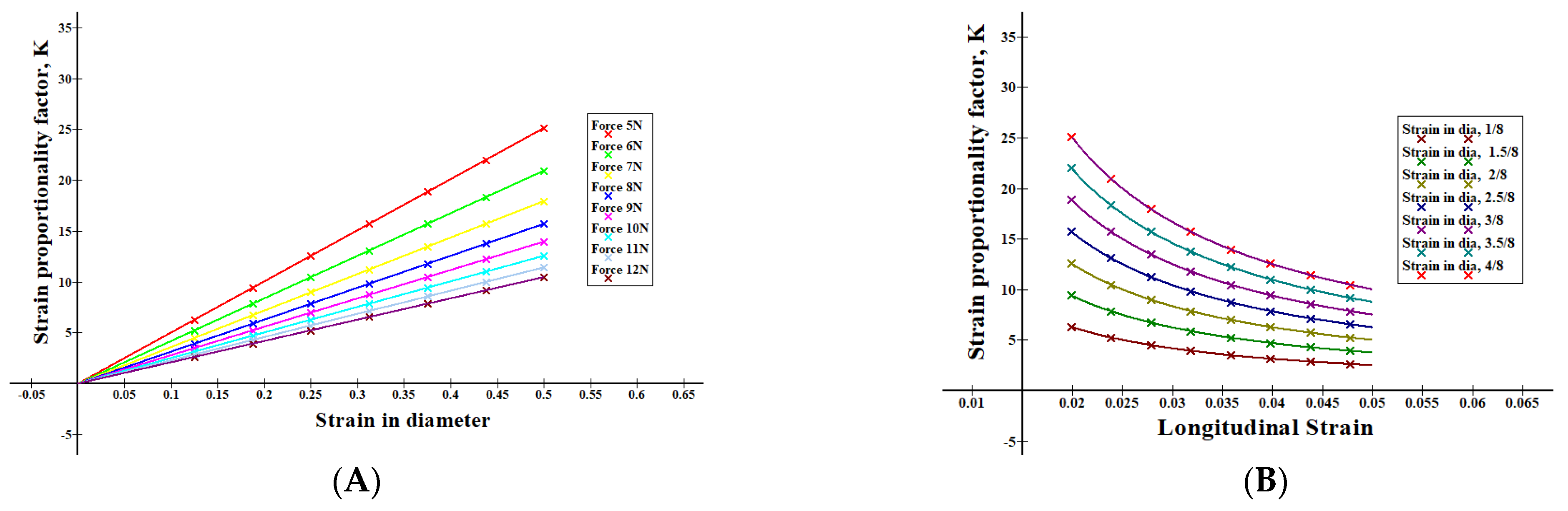
2.2. Strain Proportionality Factor

Let us consider the strains for bending and fretting point loading as ε 1 and ε 2 respectively.
Strain due to the bending load,
ε 1 = σ b E
Here,
σ b = B e n d i n g s t r e s s
E = Y o u n g s m o d u l u s
Strain   due   to   the   fretting   load ,   ε 2 = ( D d ) D
[ D = U n d e f o r m e d   d i a m e t e r   a n d   d = d e f o r m e d   d i a m e t e r ]
Similarly, strain proportionality factor can be defined as the ratio of strain due by fretting to the strain by bending, i.e.,
k = ε 2 ε 1 = ( D d ) D σ b E
Strain   Proportionality   Factor ,   k = E ( D d ) σ b D
This depends on the strain factor due to the fretting fatigue load, thus more attention should be given to the loading condition than the geometry/design.

3. Methodology

3.1. Experimental Design

As an experimental setup, a general rotating bending fatigue test rig was considered here. It mainly includes a motor, coupling, and control board with VFD, cycle counting scheme, chuck, specimen and load bearing shaft with wheel supports mounted on a fixed vibration free base. In order to imply normal bulk stress on the end of specimen, the top wheel is turned in the clockwise direction. A cut-off switch, located near the load bearing stops the motor once the specimen fails. A cycle can be counted from the frequency of the VFD and stop watch and, alternatively, from the auto cycle counting scheme, as well. Cylindrical Teflon bars were machined through a CNC lathe machine to shape into the designed specimens. Mechanical properties and technical dimensions are provided in Table 1 and Figure 3B, respectively.
In order to create the fretting phenomenon, an 8 mm bolted proving ring was prepared as shown in Figure 3D. Screwing the flat bolt through the ring, on the cylinder surface induces fretting action. Details of such a comprehensive experimental procedure are available literally and can be referred in [34,35].

3.2. Numerical Model

An FE model was developed by using ANSYS 17. For contact pair surfaces, CONTA 174 and TARGE170 were used as contact and target elements, respectively. Adaptive mesh refinement was used for mesh convergence. In order to optimize mesh refinement by saving CPU runtime at the same time, the refining process was carried out unless the stress convergence arrives within a reasonable gap. Ideally, a consecutive stress level difference of 2% was found as an acceptable range. Refinement optimization yields element size-independent results. Displacement condition was determined as Ux = Uz = 0, Uy = free. Figure 3E,F shows mesh convergence and loading sequence for fretting fatigue.

4. Results and Discussion

As expected, fretting affects the fatigue life of PTFE considerably. Based on the loading point ratio, fracture behavior was characterized. However, from a different angle of view, results can be evaluated differently.

4.1. Effect of Loading Point Ratio

Two cases were observed for fracture failure locations. For the fretting point at the loading point above 70 mm of the bending load side, the specimen cracks near the collar that experiences few fatigue cycles due to the higher strain rate [18] by the combined effect of fretting and notch. For the loading point below 70 mm, it cracks near the fretting pad location that faces more cycles for the same identical conditions for the loading point at above 70 mm from the free end, as shown in [28].
From Equation (3),
For fretting at 75 mm from the free end, LPR = 2.744, fractures near the collar.
For fretting at 70 mm from the free end, LPR = 3.375, fractures near the fretting pads.
For fretting at 68 mm from the free end, LPR = 3.68, fractures near the fretting pads.
Thus, it can be said that, the bending stiffness of PTFE lies below the LPR 3.0, i.e., below 3.0, resistance to the bending is high and the stress and strain accumulate [18] near the non-filleted collar section.
Figure 4 shows that even for a diametric strain of ½, it cracks near the collar.

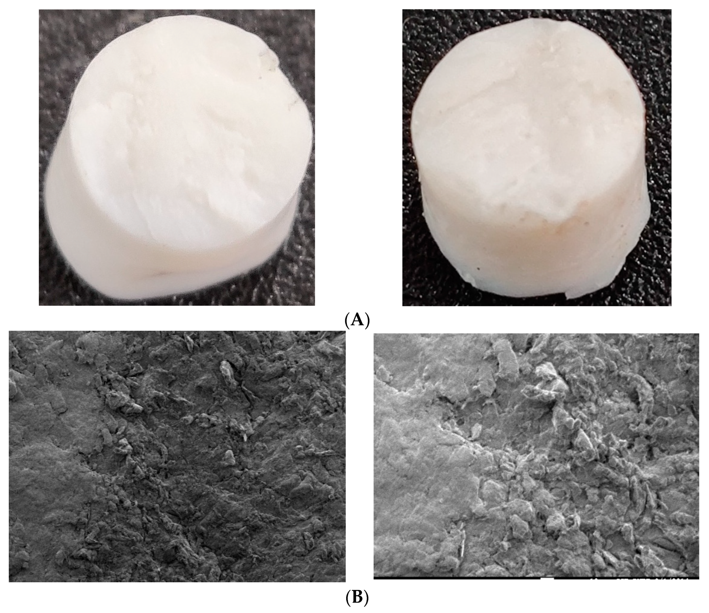
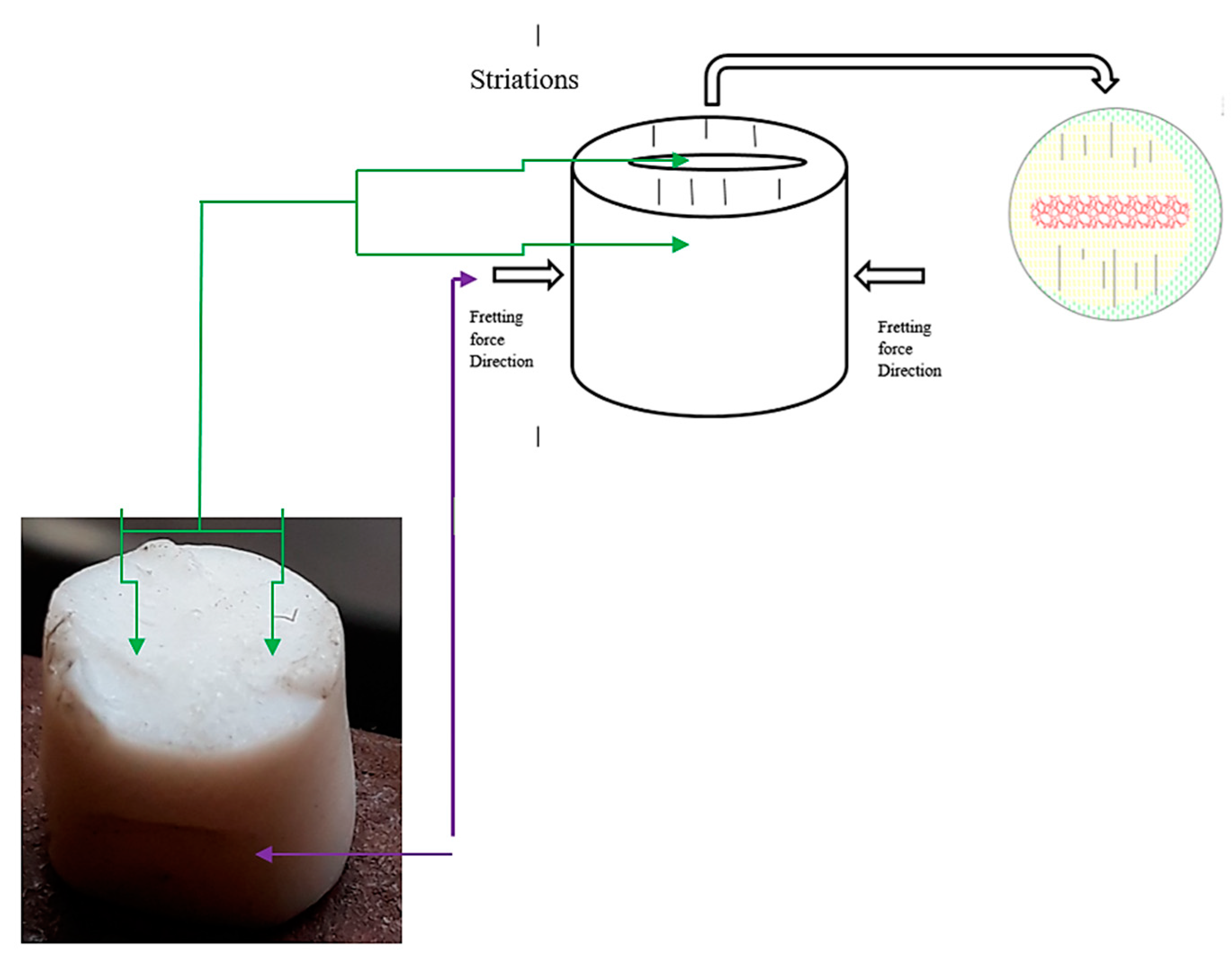
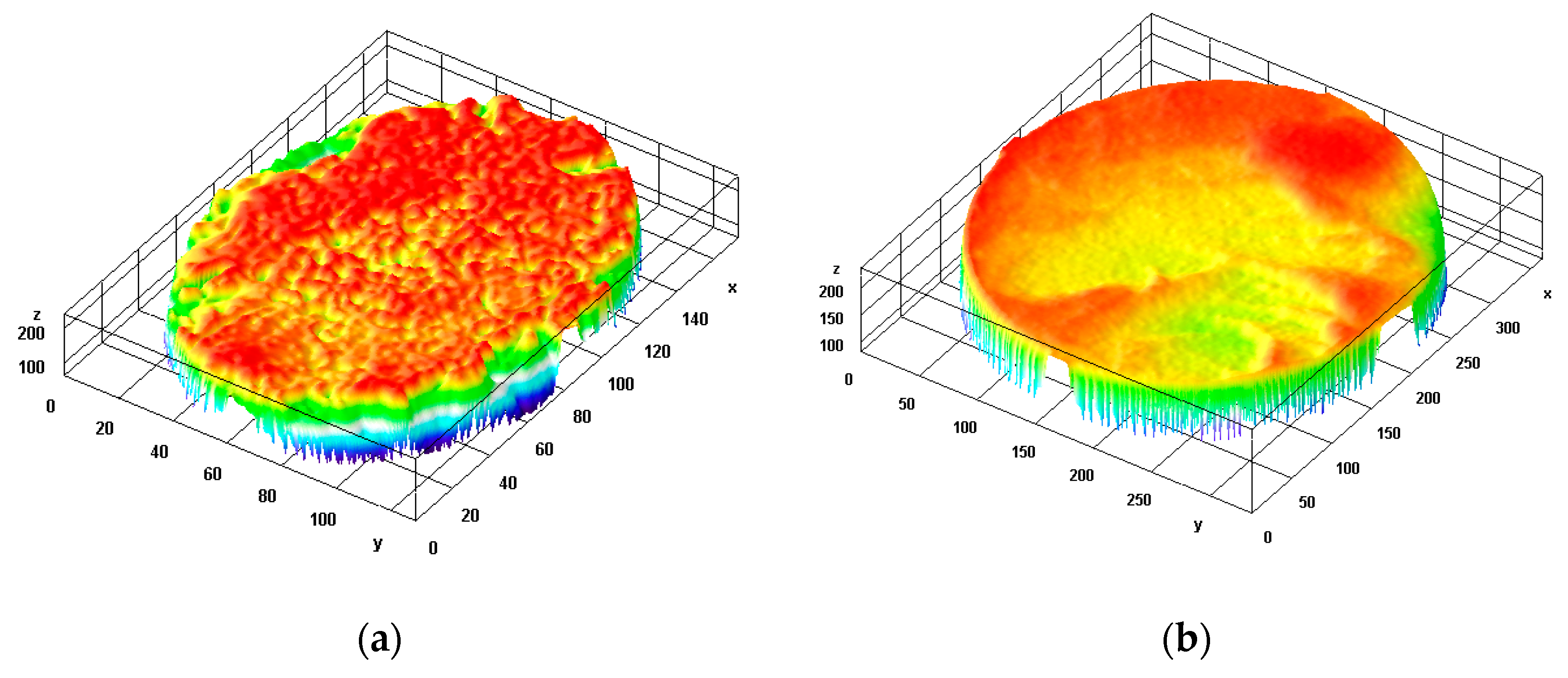
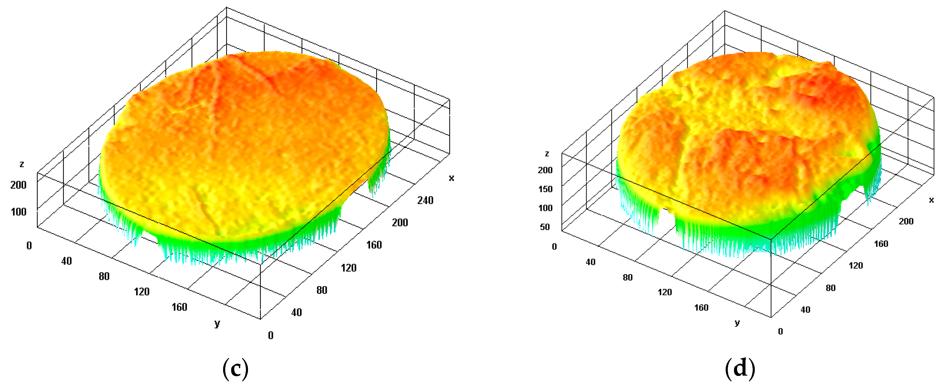
4.2. Fractography Analysis

Figure 5A shows the typical collars of PTFE samples after a fracture. If it were metals, the fracture would occur just at the sharp edge collar with a plain surface. However, a small amount of debris is left at the collar. This suggests the tearing action of the polymer at the neck. An interesting observation is that the self-weight and rotation of the fretting pad induce or try to induce a moment that creates slippage over the specimen body. Once the fretting pad locates near the collar, due to the dual effect of fretting and sharp neck a striped surface is observed as shown in Figure 5B,C (blue colored). Such striped fibers can be compared at the microscopic level with the ductile tearing fibers [7] presented in Figure 1C,D. The PTFE samples fractured just near the collar section, which implies that the stress concentration factor does not have significant effects on the failure of polymers.
Figure 6 shows debris formation and striation on the fractured surface. PTFE shows both brittle and ductile manners of fracturing. A ductile fracture causes slant lip formation while a brittle fracture shows a plain cracked surface [36]. Due to the ductile shear near the collar neck of the specimen, a crescent-type fracture with slant shear lip at 45° occurs with prominent debris. On the other hand, for LPR above 3.0, a relatively plain surface (90° brittle, tensile mode) with striation is found as shown in Figure 6b.
In order to create a simple illustration, a cracked surface schematic is shown in Figure 7.
For normal fatigue, no naked eye irregularities are found in the fractured surface. The core of the specimen exists in the middle surrounded by almost regular and smooth surfaces like a nucleus (Figure 7a). Gradual and comparatively slow crack initiation occurs at the external diameter of the body that steadily propagates towards the center. It is rough at the center because of the inability of the imbalanced body at the critical cross-sectional point to cope with the applied stress any more. However, the crack nucleates at the corner for loading greater than 70 mm and propagates like striation-benchmark/concentric rings outwards (Figure 7b). Relatively spaced striation suggests the up-gradation of stress that discontinues smoother propagation. Here, the granular-rougher rapid failed surface is found at the corner in a circular shape. Unlike normal fatigue, fretting fatigue (less than 70 mm from the free end) causes a nearly oval-shaped rough center that is perpendicular to the direction of the applied fretting load (Figure 7c). Constant rubbing of the cracked surface causes a smoother surface than the fast-growing rougher nucleus. Macroscopic lines, sometimes known as a chevron, are found in the propagation passage.
Typical fractured surfaces of PTFE, if the LPR is below 3.0, are shown in Figure 8A. Because of the fretting pressure, the polymer deforms, and is compressed (Figure 1E), hence becoming more solid through the central passage line. It becomes rougher and catastrophic failure occurs here. Striation and debris formed near the canal type rupture are shown in Figure 8B. Interestingly, this manner looks like the sliding wear condition as shown in Figure 1. If observed, it will be clear that cracks, as well as fractures, occur perpendicularly to the fretting action. A schematic drawing demonstrated the phenomenon as shown in Figure 9.
Figure 10 demonstrates a better distinguishable view for various mode of fractures on the thermal LUTs (look up tables). The maximum stressed zone is specified by the red zone. For plain fatigue, the cross-sectional area under the neck collar bears the maximum stress uniformly (Figure 10a). Under ductile fracture mode, tearing in a 45° crescent shape is obvious in Figure 10b. For brittle mode, the crack initiates at the corner in 90° that incorporates maximum stress (Figure 10c). The trough section, along with striations, is obvious for higher fretting loading when it is fractured near the fretting ring (Figure 10d).

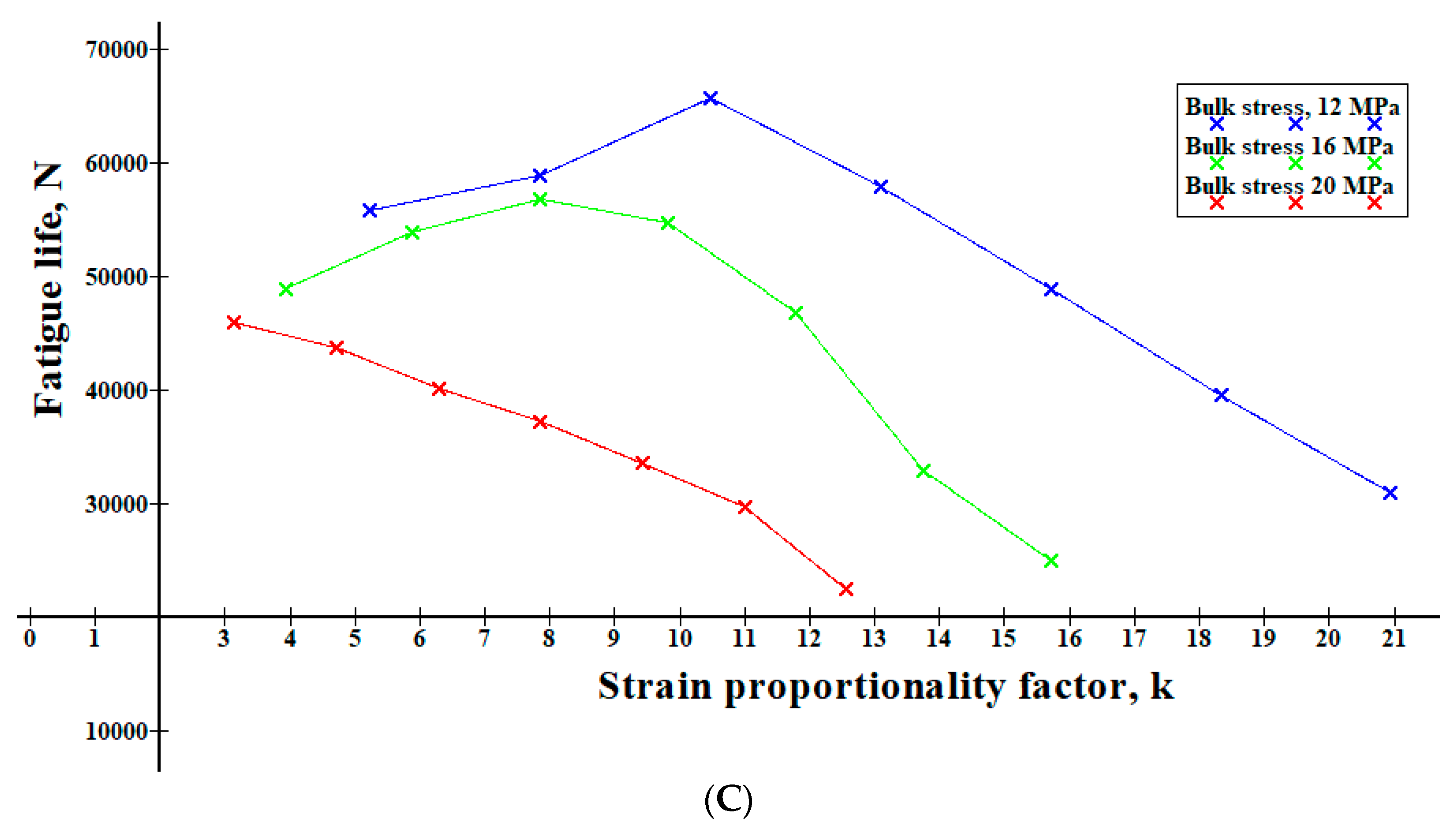
4.3. Impact of Strain Proportionality Factor

Responses of strain proportionality factor, k with the diametric strain, and longitudinal strain are shown in Figure 11A,B. Here, a similarity was found between stress concentration factor and strain proportionality factor that acts linearly to the stress and strain, respectively [37]. Even so, it also shows similarity with the relation between KI and displacement of the crack tip [38]. Interestingly, the significance of this factor may be observed for LPR > 3.0. Figure 11C shows that, for lower and middle order loading, fatigue life increases for incremental diametric strain up to a pre-intermediate level. After reaching the extreme point, it decreases again with the increment in diametric strain. Due to the mutually opposed force actions of fretting and bending loads, the shaft tries to be straightened to some degree. Thus, stress concentration, as well as strain range, is minimized that holds the fatigue life until the optimal point. After the optimal level, counterbalance of the opposite forces becomes imbalanced, hence, life degradation occurs. However, for higher-order bending load, the influence of the factor, k almost vanishes.

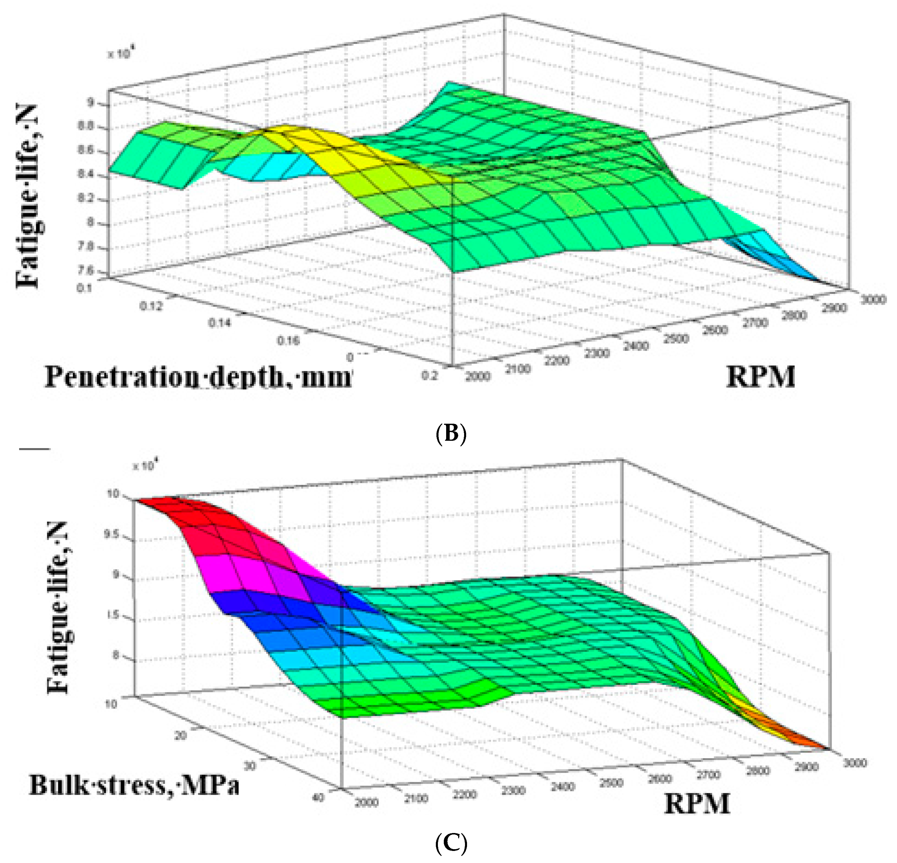
4.4. Finite Element Model (FEM) Analysis

As found earlier [28], when fretting pressure acted on more than 70 mm from the free end of the specimen, it failed at the collar section, not at the fretting zone. Stress distribution along the contact paths for both the initial and optimal fretting load steps [28] justified the way it failed. This shows that maximum higher stress concentrates at the collar edge side of the specimen. The stress distribution is shown for 30 mm distance along the contact path of the fretting pad and cylindrical specimen. Thus, the expected fracture occurs at the edge corner. However, when fretting pressure, as well as the penetration depth, is increased up to the optimal point, and fluctuating stress crest and trough limit extend at the fretting zones. On the other hand, stress upper range decreases down at the edge collar section, although it does not lie below the fretting zone side stress level to fail at that section. Thus, it develops a higher fatigue life by reducing the edge corner stress intensity/concentration.
To predict the consequence as well as observe the overall effect of variable parameters on the fatigue life of PTFE, surface graphs were created. As the frequency increases, negligible heat generation in bending fatigue is considered to accelerate the fracture failure of Teflon. Such concepts are demonstrated in the surface graphs of Figure 12. Fatigue life decreases with the increase of bulk stress as well as bending load. RPM increment shows the same results for fatigue life decrement. As found earlier, fretting pressure, as well as penetration depth, optimize the fatigue life up to a definite point.

5. Conclusions

Although well known, about 90% of fatigue life is reduced by fretting action. The aspect of fretting phenomena on fatigue strength is still being researched as well as being discovered day by day. However, for a polymer, comparatively less attention has been paid to the fretting fatigue behavior of PTFE. In this research, a new horizon has been unveiled by introducing the fracture mechanism of a polymer, PTFE, under the bending fretting fatigue phenomenon. Some measurable outcomes can be summarized as follows:
(1)
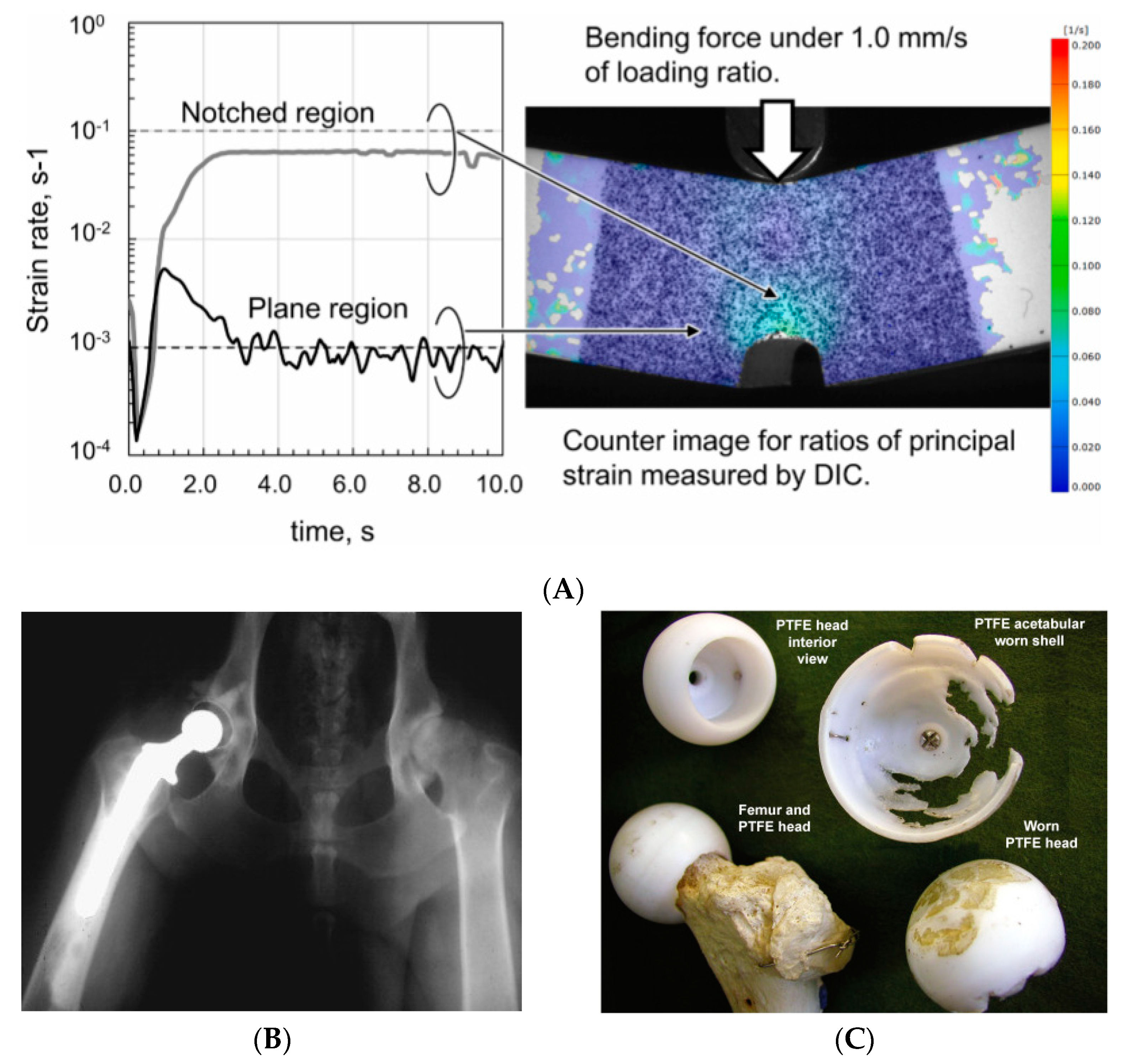
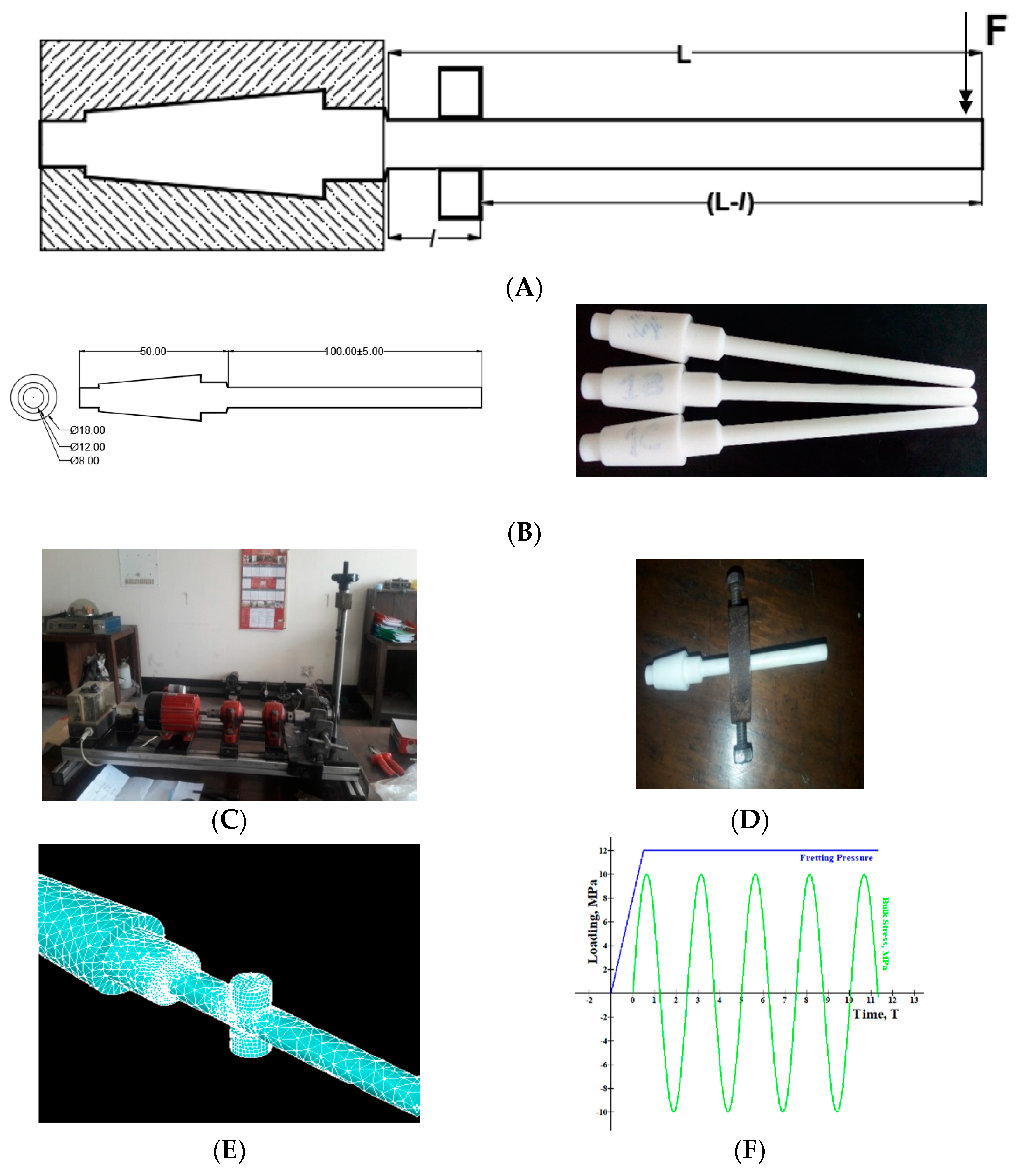
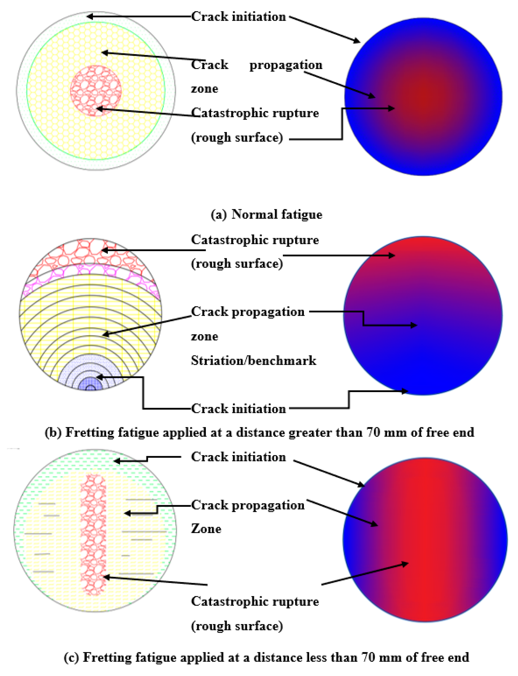
Fretting action depends on the loading point ratio. Location of fretting within 70 mm from free end causes the sample fracture near the fretting zone while for loading greater than 70 mm it causes failure near the neck point or collar due to the combined effect of fretting and notch. A mathematical model is developed and an empirical equation is derived for the loading point ratio. For LPR > 3.0, the specimen fractures at the fretting zone, otherwise at the collar section. Stress distribution along the fretting contact path supports the results obtained. Thus, it suggests a point of influence for fretting action that should be avoided while designing.
(2)
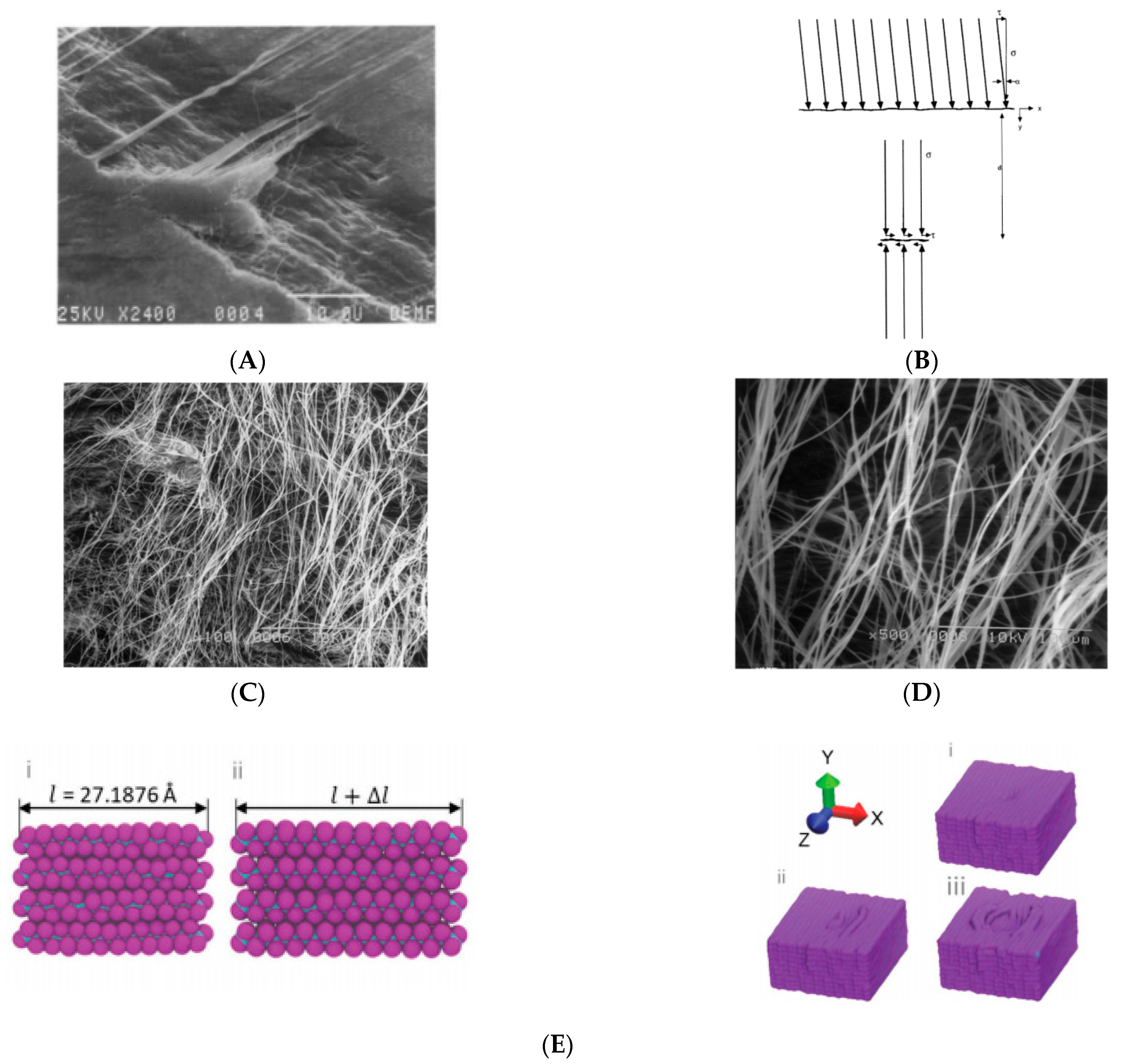
The strain proportionality factor, k, increases up to a certain (optimal) value, and improves fatigue life due to the counterbalance of the reversed (or negative) contact pressure and opposite (positive) bending stress. From finite element stress distribution, it was found that fretting compensates the excess bulk stress at the edge corner that improves fatigue life. However, once it reaches that optimal value, fatigue life starts to yield because of the loss in strength due to imbalanced necking.
(3)
From geometrical aspects and schematic demonstrations, fretting acts perpendicular to the formation of cracks. Rapid rupture occurs at an angle of 90° to the direction of fretting pressure. PTFE shows both the ductile and brittle behavior in the fractured zone. For LPR < 3.0, slant lips at 45° were found for a crescent-type fracture near the collar section. Therefore, not only the fretting quantities but also fretting qualities affect fatigue life badly.
According to the above discussion, it can be said that along with the geometric aspects, failure characteristics of PTFE depends on the loading and strain ratio with location. This could help us to develop new polymer-based biomaterial composites.

Author Contributions

Q.M.Z.S.: Conceptualized the model and established the empirical theorem, conducted the experiment, analyzed and visualized the data, designed the FE simulation, wrote the paper. M.A.K., M.A.C.: Supervised the research as well as the FE analysis, arranged computing and laboratory resources. M.A.K. Introduced the idea of “Fretting fatigue” while M.A.C. Introduced the idea of “PTFE” in this project. M.A.C., M.M.R.: Supervised and financed the project, provided materials and laboratory resources. Review & submission, Collaborated in and Co-ordinated the research as the project head. M.M.R. suggested and chose the journal for submission. M.M.R., M.T.S.C., K.A.A.: Funding Acquisition, Project Administration, Supervision & Review, Resources, Collaboration. N.H.: Participated in the manuscript revision phase. All authors have read and agreed to the published version of the manuscript.

Funding

This project was funded by the Deanship of Scientific Research (DSR) at King Abdulaziz University, Jeddah, under grant no. G-131-130-1441. The authors, therefore, acknowledge with thanks DSR for technical and financial support.

Conflicts of Interest

The authors declare no conflict of interest.

References

  1. Chowdhury, M.A.; Kowser, A.; Shah, Q.M.Z.; Das, S. Characteristics and damage mechanisms of bending fretting fatigue of materials. Int. J. Damage Mech. 2017, 27, 453–487. [Google Scholar] [CrossRef]
  2. Shah, Q.M.Z.; Chowdhury, A.; Kowser, A. On the diversity in design for different bending fretting fatigue mechanism. SN Appl. Sci. 2019, 1, 1067. [Google Scholar] [CrossRef] [Green Version]
  3. Tanaka, K.; Uchiyama, Y.; Toyooka, S. The mechanism of wear of polytetrafluoroethylene. Wear 1973, 23, 153–172. [Google Scholar] [CrossRef]
  4. Wecker, S.M.; Davidson, T.; Cohen, J.B. Study of deformation in polytetrafluoroethylene by x-ray line broadening. J. Appl. Phys. 1974, 45, 4453–4457. [Google Scholar] [CrossRef]
  5. Dao, K.C.; Dicken, D.J. Fatigue failure mechanisms in polymers. Polym. Eng. Sci. 1987, 27, 271–276. [Google Scholar] [CrossRef]
  6. Blanchet, T.A.; Kennedy, F.E. Sliding wear mechanism of polytetrafluoroethylene (PTFE) and PTFE composites. Wear 1992, 153, 229–243. [Google Scholar] [CrossRef]
  7. Aglan, H.; Gan, Y.; El-Hadik, M.; Faughnan, P.; Bryan, C. Evaluation of the fatigue fracture resistance of unfilled and filled polytetrafluoroethylene materials. J. Mater. Sci. 1999, 34, 83–97. [Google Scholar] [CrossRef]
  8. Brownell, M.; Nair, A.K. Deformation mechanisms of polytetrafluoroethylene at the nano- and microscales. Phys. Chem. Chem. Phys. 2018, 21, 490–503. [Google Scholar] [CrossRef] [PubMed]
  9. Joyce, J.A. Fracture toughness evaluation of polytetrafluoroethylene. Polym. Eng. Sci. 2003, 43, 1702–1714. [Google Scholar] [CrossRef]
  10. Rae, P.; Dattelbaum, D. The properties of poly(tetrafluoroethylene) (PTFE) in compression. Polymer 2004, 45, 7615–7625. [Google Scholar] [CrossRef]
  11. Rae, P.; Brown, E. The properties of poly(tetrafluoroethylene) (PTFE) in tension. Polymer 2005, 46, 8128–8140. [Google Scholar] [CrossRef]
  12. Brown, E.N.; Rae, P.J.; Liu, C. Mixed-mode-I/II fracture of polytetrafluoroethylene. Mater. Sci. Eng. A 2007, 468, 253–258. [Google Scholar] [CrossRef]
  13. Nunes, L.; Dias, F.; Mattos, H.D.C. Mechanical behavior of polytetrafluoroethylene in tensile loading under different strain rates. Polym. Test. 2011, 30, 791–796. [Google Scholar] [CrossRef] [Green Version]
  14. Gao, Y.; Sun, S.; He, Y.; Wang, X.; Wu, D. Effect of poly(ethylene oxide) on tribological performance and impact fracture behavior of polyoxymethylene/polytetrafluoroethylene fiber composites. Compos. Part B Eng. 2011, 42, 1945–1955. [Google Scholar] [CrossRef]
  15. Zhang, J.-F.; Ju, Y.-T.; Sun, C.-X.; Wang, P.-B. The Research on Compressive Properties of Polytetrafluoroethylene at High Strain Rate. Def. Technol. 2013, 9, 181–185. [Google Scholar] [CrossRef] [Green Version]
  16. Sonne, M.R.; Hattel, J.H. Modeling the constitutive and frictional behavior of PTFE flexible stamps for nanoimprint lithography. Microelectron. Eng. 2013, 106, 1–8. [Google Scholar] [CrossRef]
  17. Chandran, K.S.R. Mechanical fatigue of polymers: A new approach to characterize the SN behavior on the basis of macroscopic crack growth mechanism. Polymer 2016, 91, 222–238. [Google Scholar] [CrossRef]
  18. Sawada, T. Fracture criterion considering notch brittleness of polytetrafluoroethylene under quasi-static loading. Theor. Appl. Fract. Mech. 2019, 103, 102285. [Google Scholar] [CrossRef]
  19. Shah, Q.Z.; Chowdhury, M.A.; Kowser, M. Failure Mechanism of Polytetrafluoroethyleneunder Friction Fatigue. J. Fail. Anal. Prev. 2019, 19, 245–249. [Google Scholar] [CrossRef]
  20. Hobbs, J.; Burguete, R.; Heyes, P.; Patterson, E. The effect of eccentric loading on the fatigue performance of high-tensile bolts. Int. J. Fatigue 2000, 22, 531–538. [Google Scholar] [CrossRef]
  21. Meyer, R.R. Buckling of 45° Eccentric-Stiffened Waffle Cylinders. J. R. Aeronaut. Soc. 1967, 71, 516–520. [Google Scholar] [CrossRef]
  22. Surgical Research. 2001, pp. 426–441. Available online: https://www.sciencedirect.com/topics/medicine-and-dentistry/artificial-hip-joint (accessed on 15 November 2021).
  23. Charnley, J. Tissue reactions to polytetrafluoroethylene. Lancet 1963, 282, 1379. [Google Scholar] [CrossRef]
  24. Merola, M.; Affatato, S. Materials for Hip Prostheses: A Review of Wear and Loading Considerations. Materials 2019, 12, 495. [Google Scholar] [CrossRef] [PubMed] [Green Version]
  25. Zuo, J.; Xu, M.; Zhao, X.; Shen, X.; Gao, Z.; Xiao, J. Effects of the depth of the acetabular component during simulated acetabulum reaming in total hip arthroplasty. Sci. Rep. 2021, 11, 9836. [Google Scholar] [CrossRef]
  26. Seo, Y.; Wang, Z.J. Measurement and evaluation of specific absorption rate and temperature elevation caused by an artificial hip joint during MRI scanning. Sci. Rep. 2021, 11, 1134. [Google Scholar] [CrossRef] [PubMed]
  27. Cui, Z.; Tian, Y.-X.; Yue, W.; Yang, L.; Li, Q. Tribo-biological deposits on the articulating surfaces of metal-on-polyethylene total hip implants retrieved from patients. Sci. Rep. 2016, 6, 28376. [Google Scholar] [CrossRef] [Green Version]
  28. Liu, M.; Luo, Y.; Jia, D. Synthesis of mechanically durable superhydrophobic polymer materials with roughness-regeneration performance. Compos. Part A Appl. Sci. Manuf. 2020, 133, 105861. [Google Scholar] [CrossRef]
  29. Zhang, Z.P.; Rong, M.Z.; Zhang, M.Q. Mechanically robust, self-healable, and highly stretchable “living” crosslinked polyurethane based on a reversible CC bond. Adv. Funct. Mater. 2018, 28, 1706050. [Google Scholar] [CrossRef]
  30. Zhong, B.; Jia, Z.; Luo, Y.; Jia, D. A method to improve the mechanical performance of styrene-butadiene rubber via vulcanization accelerator modified silica. Compos. Sci. Technol. 2015, 117, 46–53. [Google Scholar] [CrossRef]
  31. Hamdia, K.M.; Silani, M.; Zhuang, X.; He, P.; Rabczuk, T. Stochastic analysis of the fracture toughness of polymeric nanoparticle composites using polynomial chaos expansions. Int. J. Fract. 2017, 206, 215–227. [Google Scholar] [CrossRef]
  32. Talebi, H.; Silani, M.; Bordas, S.P.A.; Kerfriden, P.; Rabczuk, T. A computational library for multiscale modeling of material failure. Comput. Mech. 2013, 53, 1047–1071. [Google Scholar] [CrossRef] [Green Version]
  33. Aherwar, A.; Singh, A.K.; Patnaik, A. Current and future biocompatibility aspects of biomaterials for hip prosthesis. AIMS Environ. Sci. 2015, 3, 23–43. [Google Scholar] [CrossRef]
  34. Shah, Q.M.Z.; Chowdhury, M.A.; Kowser, A. Fretting & friction induced fatigue failure: Damage criterion of polytetrafluoroethylene. Heliyon 2020, 6, e04066. [Google Scholar] [CrossRef]
  35. Zobaer, S.; Quazi, M.; Arefin, K.; Mohammad, A.C. A parametric investigation on the fretting fatigue behaviour of heat treated Al 6061-T6 under rotating bending phenomena. Aust. J. Mech. Eng. 2019, 1–13. [Google Scholar] [CrossRef]
  36. Perez, N. Fatigue Crack Growth. In Fracture Mechanics; Springer: Cham, Switzerland, 2017; pp. 327–372. [Google Scholar]
  37. Perez, N. Linear-elastic fracture mechanics. In Fracture Mechanics; Springer: Cham, Switzerland, 2017; pp. 79–130. [Google Scholar]
  38. Perez, N. Crack Tip Plasticity. In Fracture Mechanics; Springer: Cham, Switzerland, 2017; pp. 187–225. [Google Scholar]
Figure 1. (A) Electron image of strip formation and (B) schematic drawing of crack [6], and micrograph of damage species on the fracture surface within the stage of stable crack propagation for the virgin polytetrafluoroethylene (PTFE) (C) 100×, (D) 500× [7], Deformation and indentation of PTFE [8] (E).
Jcs 06 00031 g001
Figure 2. (A) Bending test results of PTFE under quasi-static loading [18], (B) hip joint cup and (C) biological implants showing PTFE components [22].
Jcs 06 00031 g002
Figure 3. (A) cylindrical cantilever beam under bending fretting fatigue. (B) Designed specimen (dimensions are in mm). (C) Meshed geometry (D) conditional loading, (E) rotating bending fatigue setup, and (F) fretting proving ring.
Jcs 06 00031 g003
Figure 4. Cracked specimen for fretting ring distance above 70 mm (left), and deformed diameter (right).
Jcs 06 00031 g004
Figure 5. (A) Typical fractured heads showing debris of the cylindrical body, fresh specimen (B), tested specimen after certain cycle’s period (C).
Jcs 06 00031 g005
Figure 6. (a) Crescent shaped edge. (b) fractured surface for lower fretting depth.
Jcs 06 00031 g006
Figure 7. Schematic diagram of fractured PTFE surface.
Jcs 06 00031 g007
Figure 8. (A) Typical fractured surface cracked near the fretting zone. (B) Debris and striations near canal type rupture.
Jcs 06 00031 g008
Figure 9. Schematic demonstration of fracture failure.
Jcs 06 00031 g009
Figure 10. Typical thermal LUTs (look up tables) on fractured surfaces, (a) normal mode (plain fatigue), (b) crescent (ductile) mode, (c) brittle mode (initial order fretting), (d) trough mode (high order fretting).
Jcs 06 00031 g010aJcs 06 00031 g010b
Figure 11. Relationship between (A) k and diametric strain, (B) k and longitudinal strain, (C) relationship between fatigue life and strain proportionality factor.
Jcs 06 00031 g011aJcs 06 00031 g011b
Figure 12. (A) Relationships for bending stress, (B) relationships for RPM, penetration and fatigue life and (C) fatigue life and penetration relationships for bending stress, RPM and fatigue life.
Jcs 06 00031 g012aJcs 06 00031 g012b
Table 1. Mechanical properties.
MaterialDensity (g/cc)Youngs Modulus, E (GPa)Poisson’s RatioYield Tensile Strength, YTS (MPa)Ultimate Tensile Strength, UTS (MPa)
Teflon (PTFE)2.30.50.463043
Publisher’s Note: MDPI stays neutral with regard to jurisdictional claims in published maps and institutional affiliations.

