Article

Thermal Qualification of the UHTCMCs Produced Using RF-CVI Technique with VMK Facility at DLR

1
School of Metallurgy and Materials, University of Birmingham, Birmingham B15 2SE, UK
2
Deutsches Zentrum für Luft-und Raumfahrt, DLR, German Aerospace Center (DLR), Institute of Aerodynamics and Flow Technologies, 51147 Cologne, Germany
*
Authors to whom correspondence should be addressed.
J. Compos. Sci. 2022, 6(1), 24; https://doi.org/10.3390/jcs6010024
Submission received: 2 December 2021 / Revised: 31 December 2021 / Accepted: 4 January 2022 / Published: 11 January 2022
(This article belongs to the Special Issue Ceramic-Matrix Composites)

Abstract

:
Ultra high-temperature ceramic matrix composites (UHTCMCs) based on carbon fibre (Cf) have been shown to offer excellent temperature stability exceeding 2000 °C in highly corrosive environments, which are prime requirements for various aerospace applications. In C3Harme, a recent European Union-funded Horizon 2020 project, an experimental campaign has been carried out to assess and screen a range of UHTCMC materials for near-zero ablation rocket nozzle and thermal protection systems. Samples with ZrB2-impregnated pyrolytic carbon matrices and 2.5D woven continuous carbon fibre preforms, produced by slurry impregnation and radio frequency aided chemical vapour infiltration (RF-CVI), were tested using the vertical free jet facility at DLR, Cologne using solid propellants. When compared to standard CVI, RFCVI accelerates pyrolytic carbon densification, resulting in a much shorter manufacturing time. The samples survived the initial thermal shock and subsequent surface temperatures of >2000 °C with a minimal ablation rate. Post-test characterisation revealed a correlation between surface temperature and an accelerated catalytic activity, which lead to an understanding of the crucial role of preserving the bulk of the sample.

1. Introduction

The recent return of supersonic flight to aviation could significantly shorten long-haul flight times [1,2,3,4,5]. However, the leading edges of these vehicles, as well as the nozzles of solid or hybrid rocket motors, must resist the harsh temperature, chemical and mechanical environments created by high-performance solid propellants to be commercially successful [6,7]. Some fuels are extremely corrosive, with flame temperatures ranging from 2700 to 3500 °C. In addition, the interplay of external factors with the requirement to maintain dimensional stability of the nozzle throat makes choosing appropriate materials particularly difficult. Current engineering materials cannot withstand severe temperatures and chemically harsh conditions, as well as rapid heating and cooling [3,4].
A modern group of materials, the ultra-high temperature ceramic-matrix composites (UHTCMCs), are a new subfield within the broader grouping of ceramic matrix composites and are potential candidates for such applications [8]. They combine the benefits of CMCs, such as high-temperature strength and stiffness, low specific weight and damage tolerance with oxidation and ablation resistance at extreme temperatures, e.g., >2000 °C [9]. The processing and engineering of these UHTCMCs is very challenging, however.
Researchers have developed a range of successful routes including slurry infiltration, precursor infiltration and pyrolysis (PIP) [10], reactive melt infiltration (RMI) [11,12], spark plasma sintering (SPS) [13] and chemical vapor infiltration (CVI) [14,15]. A recent European research programme (Next Generation Ceramic Composites for Combustion Severe Environments and Space, C3Harme, EU Horizon 2020 research funding agreement number GA 685594) brought together a number of academic and industrial partners to assess and evaluate a range of UHTCMCs for two primary, civilian, end-applications, leading edges for hypersonic vehicles and rocket nozzle throats [3,4,16].
This paper focuses on a route to Cf-UHTCMCs that involved the tailored slurry impregnation of carbon fibre preforms with zirconium diboride (ZrB2) with the remaining porosity being filled with pyrolytic carbon using the relatively low temperature (~1000 °C), near net-shape, chemical vapour infiltration (CVI) process) [3,17]. Since conventional CVI is particularly slow, it can easily take ~1000 h to densify components, the University of Birmingham has developed radio frequency-assisted heating (RF-CVI), which accelerates the deposition process by up to around a factor of 40. The resulting composites were subsequently evaluated at DLR using the simultaneous internal (solid propulsion) and external flow in their vertical free jet (VMK) facility [18]. Validation of the results was ensured by involving leading sector end-users, AVIO and AIRBUS, in the C3Harme consortium.

2. Materials and Methods

2.1. Materials Processing

The starting materials for preparing UHTC composites were zirconium diboride (ZrB2) powders, carbon fibre preforms and ethanol. The ZrB2 powders (HC Starck grade B, d50 ≈ 3 μm) were procured through ABCR GmbH & Co, Karlsruhe, Germany. The structure of the 2.5D continuous carbon fibre (Cf) preforms, which contained 23 vol% Cf, consisted of layers of fabric stacked in an arrangement of random/0°/random/90°/random orientation fibres, where 0° and 90° were unidirectional layers and the random layers were formed as a result of manufacturer’s (Surface Transforms, Liverpool, UK) needling process.
The ZrB2 slurry impregnation procedure has been explained in detail elsewhere [19] and hence won’t be repeated here. The resulting ZrB2 impregnated preforms were densified with pyrolytic carbon (PyC) using RF-CVI with heating provided by an EasyHeat induction furnace operating at 4.2 kW maximum power in the frequency range of 150–400 kHz. Methane in a hydrogen carrier gas was used as the precursor for PyC formation. The parameters of the RF-CVI process, i.e., the best temperature and flow rate, were optimised to maximise the pyrolytic carbon deposition rate. The target temperature was controlled using a two-wavelength pyrometer (CTRM-1SF40-C3, Micro-Epsilon Messtechnik GmbH & Co, Ortenburg, Germany).

2.2. Post Test Materials Characterisation

The ablated UHTCMCs surface profile was analysed using a surface profile analyser (InfiniteFocus, Bruker Alicona Imaging GmbH, Graz, Austria), whilst the oxide scales, crystal structure and phase formation were examined using X-ray diffraction (Bruker D8, Coventry, UK) and confirmed using Raman spectroscopy (Via Reflex, Reinshaw, New Mills, UK). The ablation region was sectioned into thin strips for cross-sectional analysis using a precision vertical diamond wire saw (Well 4500, WELL Diamond Wire Saws SA, Le Locle, Switzerland). The ablated surface and cross-section microstructures were characterised using scanning electron microscopy (JEOL 7000, Tokyo, Japan) with wavelength dispersive X-ray spectroscopy, WDS.

2.3. VMK Test Facilities

The UHTCMC-materials prepared using RF-CVI were tested at the German Aerospace Agency (DLR, Cologne, German) in Cologne’s Vertical Free Jet Facility (Vertikale Messstrecke Köln, VMK, Cologne, German). The Vertical Free Jet Facility is a conventional blow down wind tunnel with vertical free jet test section. The facility can operate between Mach 0.5 to 3.2. The vertical alignment of the free jet, along with a wide range of flow conditions, enables testing across a broad range of technology development. The test section has a size of 4 m × 4 m and is placed inside a tower of 11 m height. It is equipped with different supports to hold the samples along with supports to adjust the angle of attack. The nozzle in the test section is exchangeable and, depending on the required Mach number, subsonic or supersonic nozzles could be used. More detailed information has been provided in [18].

2.4. Specimen Preparation

The UHTCMC test specimens were mounted individually on a wedge model and exposed to a hot plume as shown in Figure 1. Flat plates of 50 × 50 mm and a thickness of 5 mm were used for tests. The corners of the specimen were rounded and had a radius of 5 mm. The wedge with the sample was adjusted to the plume in such a way that the inclination of the specimen to the axis of the nozzle had an angle of 20°, see Figure 1. The distance of the samples to the nozzle exit varied depending on the propellant used.
The surface temperature on both the front and back side of the flat plate were measured during the tests; that at the front using IR-thermography and a two-colour pyrometer, whilst the back face temperature was measured using a mounted thermocouple. A 3D measurement system, Keyence® VR 5000, was used to investigate the erosion of the materials. The plume flow around the model were visualised using high-speed Schlieren optics in association with a high-speed camera FASTCAM SA-X2 (Photron, Reutlingen, Germany).

2.5. Test Conditions

The combustion of propellant grains generates the thermal and mechanical loads on the specimens. Two propellant grains, both based on hydroxyl-terminated polybutadiene, HTPB, and two throat diameters were used to develop two different flow conditions, Table 1. The main difference in the propellant grains used was the chemical fraction of aluminium present, which was 2% and 8%.

3. Results and Discussion

3.1. Starting Materials

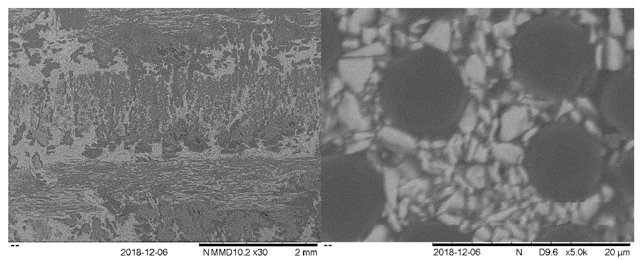
The UHTCMCs prepared contained 23 vol% carbon fibres, slurry-impregnated with 25 vol% ZrB2 powders and then densified with 43 vol% pyrolytic carbon via the RF-CVI process. The densities and open porosities of the samples were 2.7 g/cc and ~9% respectively and the pyrolytic carbon had a rough laminar structure, Figure 2.

3.2. Propulsion Test Results (DLR)

3.2.1. Phase 1 Tests

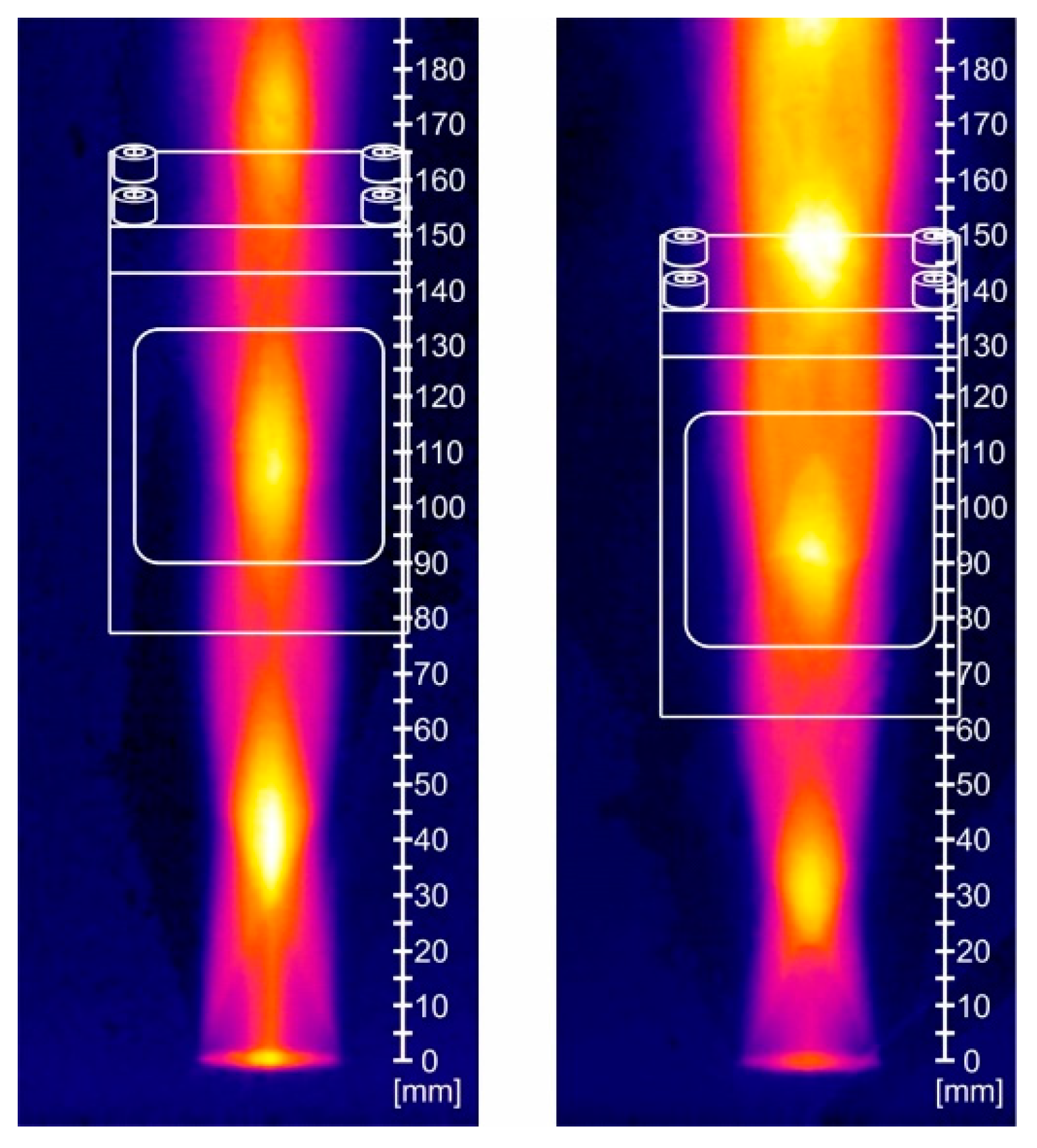
In preparation for the subsequent material investigation tests, some preliminary tests were carried out in the VMK to analyse the plume jet in order to determine the appropriate position for the sample holder. Based on these results, appropriate positions were identified for both sets of flow conditions, these are shown in Figure 3 for the propellant containing 2% Al (left) and 8% Al (right). The figure shows infrared images of the plume overlapped with the CAD images of the model holder and the distance measurements show the distance from the nozzle exit.

3.2.2. Phase II Tests

The surface quality of the UHTCMC materials was investigated before the samples were exposed to the plume and a typical surface is shown in Figure 4. The measurements indicated that the surfaces were relatively rough and had machining marks; for the sample shown, the fibre orientation is in the vertical direction. The measured roughness values in both vertical and horizontal directions are summarised in Table 2.
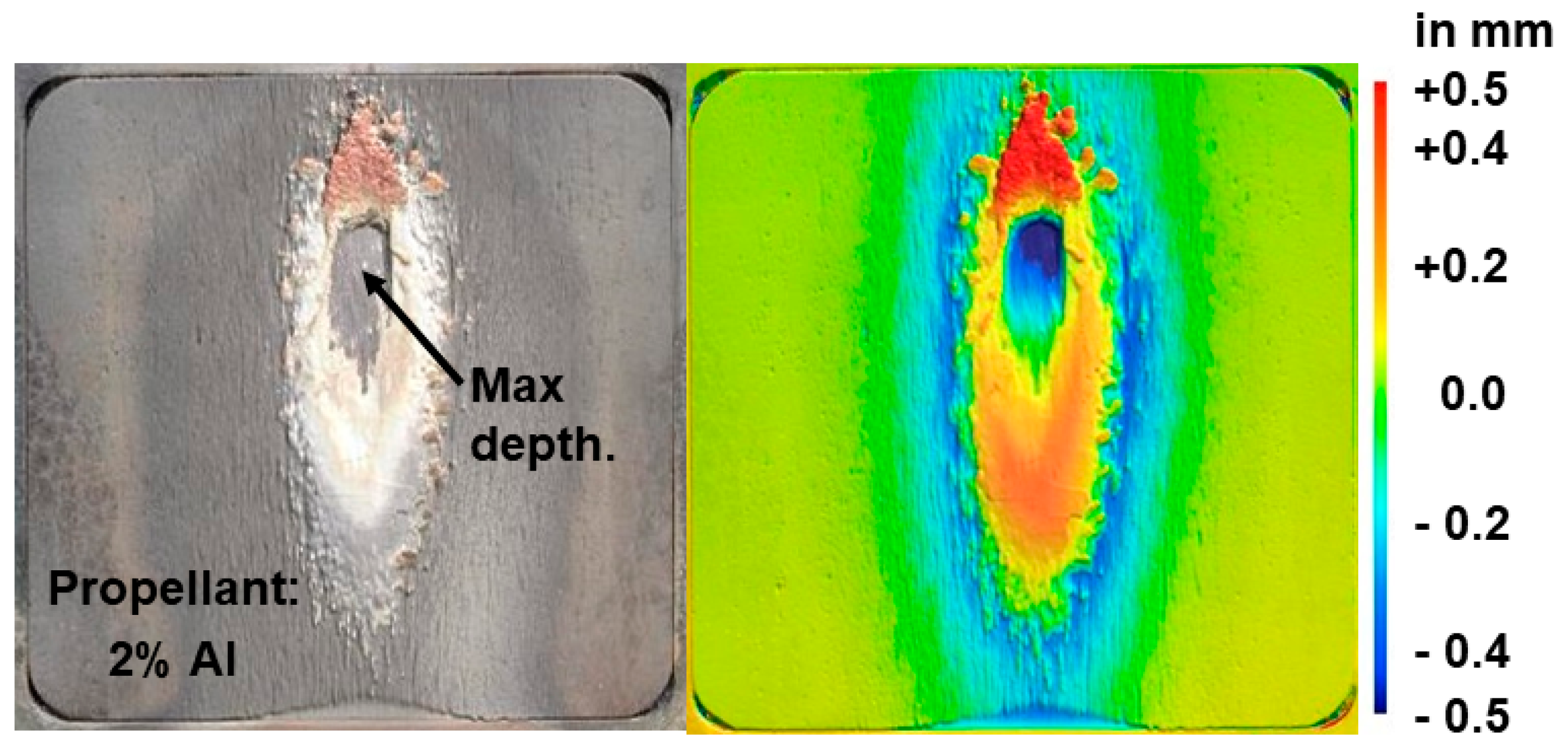
The samples were subsequently exposed to the hot plume and Figure 5 shows the results for a sample exposed to a plume arising from the use of 2% Al propellant. The image on the left is a simple picture, whilst that on the right shows the height variations for the same image.
The damage to the flat plate’s surface indicates both erosion and subsequent deposition. Most of the former occurred along the vertical symmetry line of the sample at the point of contact of the plume, whilst the deposition occurred after the plume was switched off and immediately surrounding the area of maximum erosion. The erosion at the bottom centre of the sample, where the sample met the model holder, is clearly visible in the optical view. Because of the deposits occurring during cooling, it is challenging to determine the amount of the eroded material mass and the extent of erosion, however the maximum depth of erosion was −0.755 mm. This yielded an estimated maximum recession rate of 0.84 mm/s.
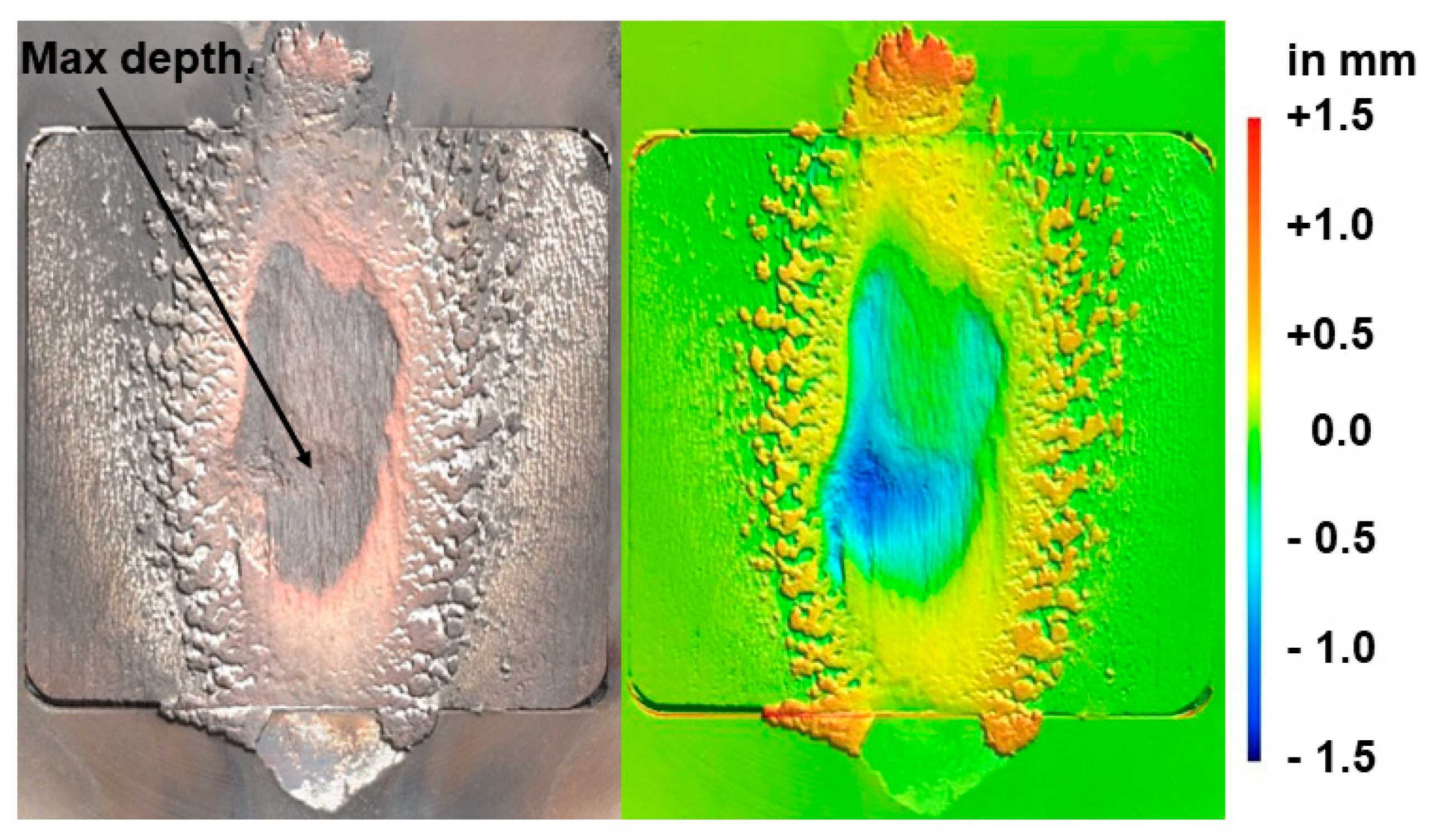
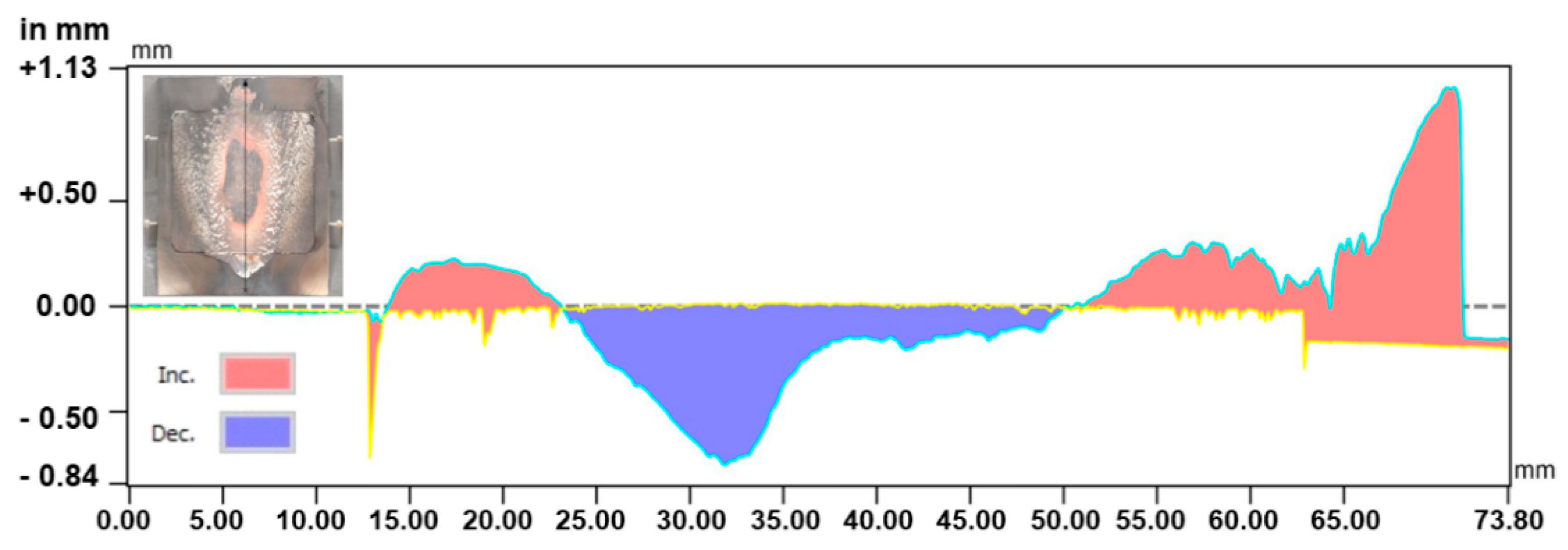
Figure 6 shows the equivalent results for the propellant with 8% aluminium; the temperatures were much higher as outlined above. However, whilst it is assumed that more erosion will have occurred, it has also led to much greater deposition after the plume was terminated. The oxidised residue was distributed much more broadly over the sample, again making it hard to see what originally happened underneath, but the greater fraction that resembles splashes suggests that there has been more liquid formed. Once again, there is a region free of residues, which presumably marks the region that remained hot the longest. Comparison of the distance scales to the right of Figure 5 and Figure 6 shows that both the depths and heights were much greater with the 8% Al and the value for the maximum depth yields a maximum depth of erosion of −1.545 mm. This yielded a recession rate of 1.19 mm/s, which is ~40% higher than for the 2% Al propellant.
The height difference plot along the vertical symmetry line shown in Figure 7 for the erosion damage to the sample caused by the 8% Al propellant plume occurred over a long distance. As a result of the short residence duration of the hot gases, shallow angles of attack, such as 30°, encounter comparatively low static pressures and may experience a lower surface temperature, resulting in a higher mass ablation rate per unit of damaged surface [20].
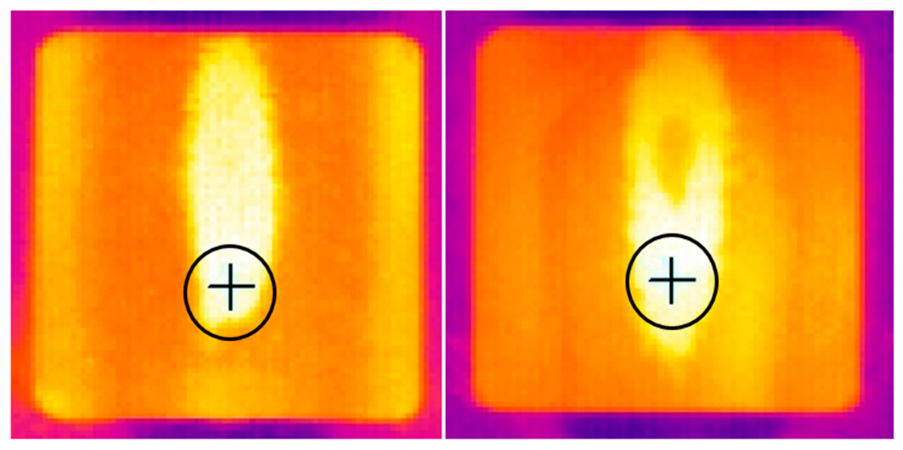
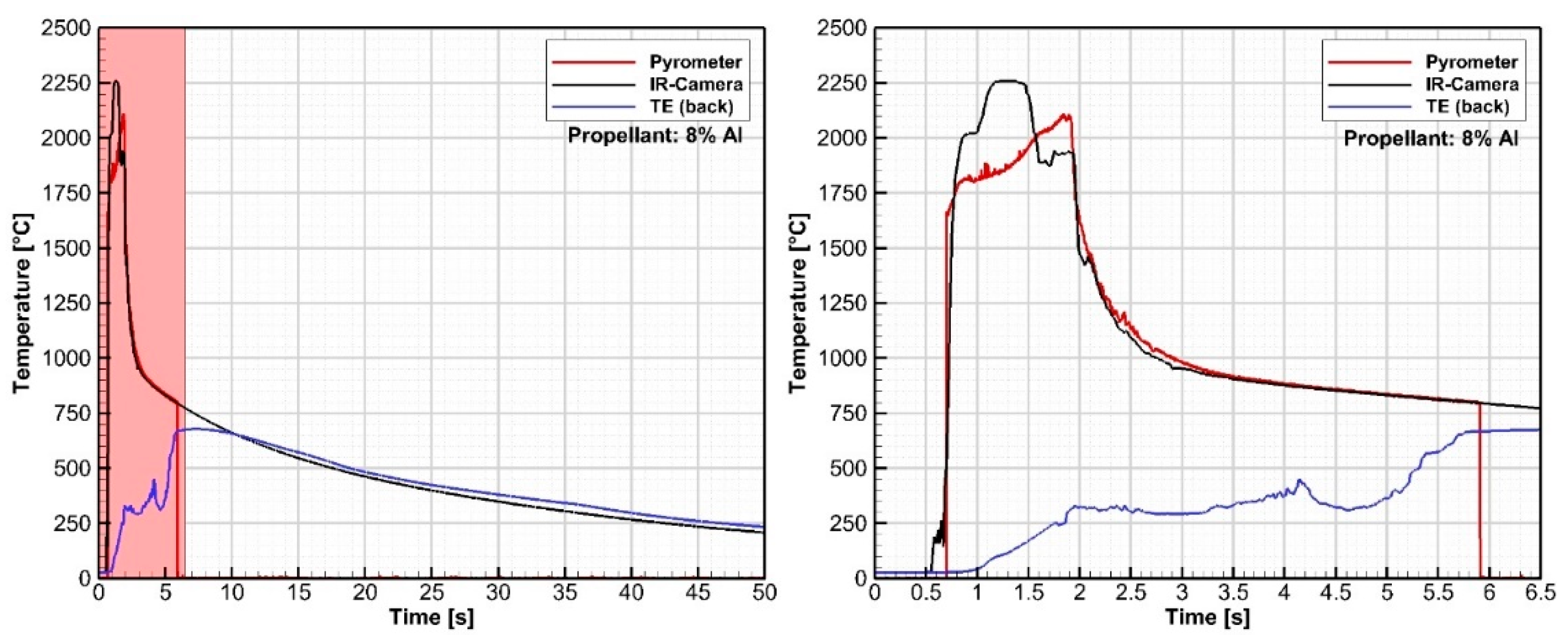
The effectiveness of the temperature insulation created by the UHTCMC was investigated by comparing the temperature data measured on the front and 3 mm beneath the front surface (called the back temperature) of the sample. As indicated previously, a two-colour pyrometer and infrared thermography were used to determine the temperature on the front surface exposed to the plume and Figure 8 shows the results from the thermography with the location of the pyrometer focus being shown by the circles and the pixel used to provide the thermography data marked by the crosses. The so-called back temperature was measured by a Type K thermocouple fixed in a 2 mm deep hole in the middle of the rear surface. The measurement acts as an indication to the evaluate the protective behavior of the ablated oxide layer formed on the test material during the test. Comparisons of the temperature measurements are shown in Figure 9 (2% Al propellant) & Figure 10 (8% Al propellant). In both cases, the left-hand figures show the temperature trends across the duration of the test, whilst the righthand plots show the data for the first few seconds, the time when testing actually took place. The same time period is marked with the red shading in the left-hand plots. It is interesting to note that the pyrometer and IR-thermography measured similar temperatures, with the maximum front temperature being in the range 1600–1700 °C for the test using 2% Al propellant, whilst the temperature exceeded 2000 °C with the 8% Al propellant. As expected, the back temperatures were much cooler and continued to rise for a few seconds after the plume was terminated. The test with 8% Al propellant shows what looks like vibrations from the combustion in the back temperature measurement, but it is believed that the fundamental trend shown will be reasonably correct.

3.2.3. Post-Test Characterisation

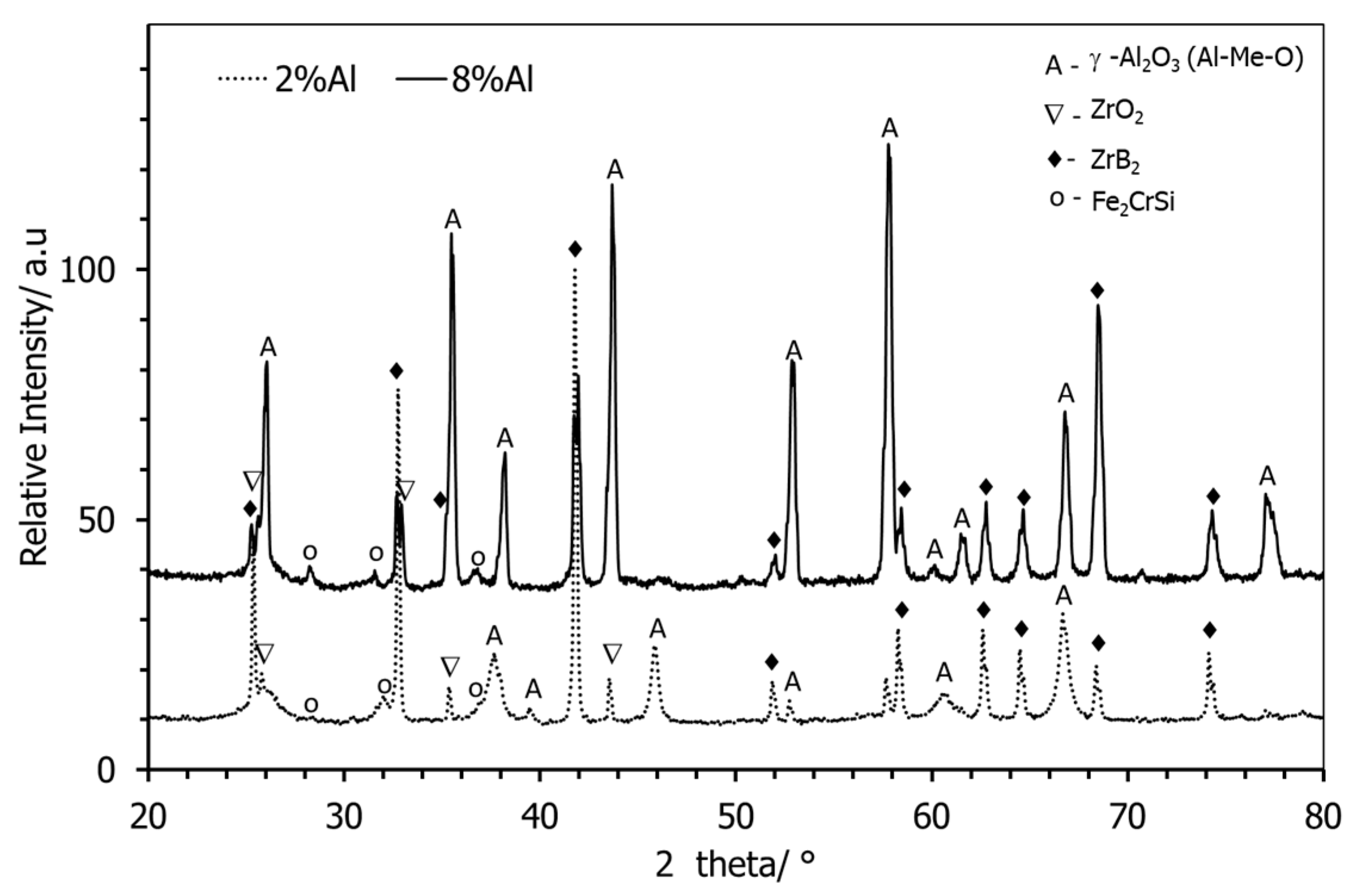
Figure 11 shows the X-ray diffraction pattern of the ablated UHTCMC surfaces; it is apparent that fine tetragonal zirconia and modified γ -alumina particles were formed; the former presumably from the oxidation of the ZrB2 in the UHTCMC and the latter from the propellant. Interestingly, with increasing Al concentration in the propellant, there was a significant increase in the ZrO2, suggesting greater oxidation of the composite due to the higher temperature achieved (due to the increased catalytic activity of the Al in higher concentrations), whilst the alumina level remained approximately the same. The presence of ZrB2 peaks for the sample tested with a higher concentration of Al validates the partial exposure of fresh base composite surface due to ablation.
The ablated surface was further characterised using Raman spectroscopy, Figure 12. The peaks, which were very similar for both the 2% Al and 8% Al propellants, confirm the stabilisation of the ZrO2 in the tetragonal phase, whilst there is also evidence of boria presence as a result of the ZrB2 oxidation. The peaks at ~1300 cm−1 and ~1575 cm−1 refer to the D & G band of the pyrolytic carbon from the base composite matrices. The D-band indicates the degree of disorder in the graphene layers, whereas the G-band indicates the stretching of C-C bonds in graphitic materials. In addition, the intensity ratio between the two bands is inversely proportional to the degree of graphitisation [21]. Thus, on the ablated surface, the intensities of the D and G bands for carbon are nearly the same, which infers the retention of a good level of graphitisation and perhaps originated from the fresh surface of the base material. In addition, the peak at 2700 cm−1 confirms the long-range coherence of the carbon.
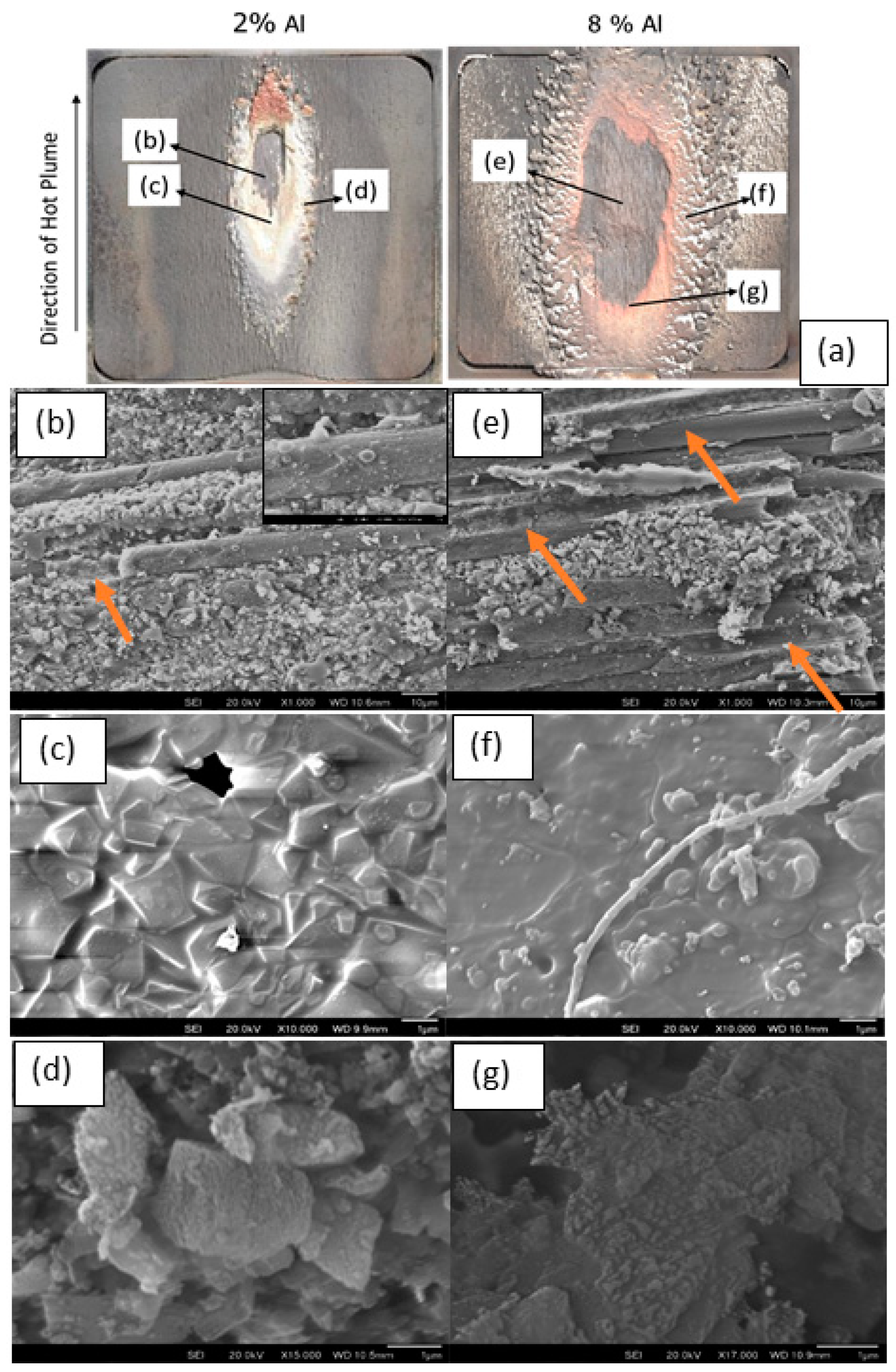
The SEM analysis of the ablated surface obtained after using the 2% and 8% Al-based propellants, as shown in Figure 13b,e, shows loosely spread fine mixed oxide layers of alumina and zirconia at the centre of the ablation region. Traces of both iron and silicon may also be observed to be uniformly spread across the sample surface, and this is assumed to have originated from the sample holder. There is no detectable significant chemical reaction observed with the base material on the ablated surface, this could be due to the shorter residence time. No sintering of the oxide layer was observed. Figure 13 also depicts some of the characteristic features of the carbon fibre tows embedded with the mixed oxide on the ablated surface morphologies. Additionally, traces of burnt-out carbon fibre were also noticeable in the central hot spots of the ablated region, as marked using arrows on Figure 13b,e. Further, the spreading of liquid boria from the oxidation of the ZrB2, due to its viscous nature, see Figure 13b inset, could be witnessed on some of the remaining carbon fibres. However, in the intermediate temperature range of 977–1477 °C, the passivation created by B2O3 deteriorated due to its volatilisation [22], also leaving a porous ZrO2 layer, Figure 13b inset. Overall surface morphologies were similar in the ablation region on the samples ablated using the 8% Al concentration, except that the ablation region was wider & deeper and there was a significant deposition of the ablated materials along the area covered by the hot plume. The morphology of the gathered deposit from the ablation shows the condensed structures with embedded oxide particles, Figure 13c,f. Interestingly, the high magnification images of the region near the start of the hot plume also showed the fine refractory oxides to be covered by boria, Figure 13d,g. Further examination of the cross-sectional analysis of the ablated region on the sample tested using 2% Al concentration revealed detailed information on the interface of the ablated surface with the base material, Figure 14, respectively. Oxygen diffusion remains limited to the sample surface whilst the impact of Al from the fuel mixtures also stays on the sample surface, with minimal diffusion through the base material.
Both ZrO2 from the oxidation of ZrB2 and Al2O3 from the propellants were stable for oxygen partial pressures up to 10−16 and 10−22 respectively at >1600 °C [22,23,24]. From the equilibrium phase diagram of Al2O3-ZrO2, it is evident that the mixture has a eutectic temperature at 1860 °C with a composition of about 58% alumina [25]. Although alumina and zirconia have complete solubility in a liquid state, it is very limited in the solid state; <2% for alumina in solid zirconia and nearly zero for the reverse. These limited solubilities in the solid-state could maximise the stabilisation of the amorphous and various metastable phases during the rapid solidification of the composites [23], however, the oxides remain separate and only embedded by the liquid boria before it froze when the sample cooled.
One of the main criteria for solid propellant is their low ignition temperature, therefore the aluminum particulates, once ignited, form a combustion front and the metal particles begin to melt due to the heat released from the reaction of oxidizer and fuel binder [26]. The molten particles tend to agglomerate together and begin to combust due to the aluminum oxidation reaction forming a core-shell structure with molten Al trapped inside closed oxide caps [27]. The two try to separate out since they are insoluble, whilst oxygen tries to diffuse in through the oxide cap and aluminum tries to diffuse out of it. Thus, the inner liquid metal core holds a higher internal energy for a fusion reaction within the small region. These core-shell particles, with average temperature greater than 1543 °C but less than the melting temperature of Al2O3 at 2072 °C, are most likely agglomerated to reduce the surface energy; some are partially sintered and not acting either as a binder nor as a burn inhibitor [28]. The drag forces created by the combustion in the reaction flame zone spreads these particles to the surrounding gases and directs them towards the sample surface by the local convective flow. Therefore, these highly active oxide particles hit the sample surface releasing large amounts of energy and creating an acidic catalysis [29,30] reaction. Note, the sample surface is covered with excessive liquid boria, and this has been considered to reduce or suppress the catalytic activity by bringing down the oxide melting temperature, thereby reducing the number of reaction sites for further oxidation and ablation [29,30]. Therefore, it is believed that the significant ablation observed on the sample surface has been primarily triggered by the high erosion and friction created by the gas velocity and, in particular, the relevant shallow angle of attack as described in previous work on a different UHTCMC system elsewhere [20]. Consequently, the suppressed reaction products containing amorphous Al with some embedded Al2O3 and ZrO2, along with traces of B and C, becomes accumulated along the gas exit direction. A schematic of the ablation and catalytic reaction mechanism for the present materials system has been highlighted in Figure 15. Typically, when the sample was tested at a shallow angle of attack, e.g., ~20°, the shear force generated dominated the ablation behaviour rather than the static pressure that accumulated during the 90° angle of attack testing. Therefore, the present system resulted in an increased area of erosion compared to the pressure-assisted denudation that occurs under a 90° angle of attack for a similar peak temperature. Similar concepts have been observed during ultra-high temperature testing using an oxyacetylene torch at low angles of attack [20].

4. Conclusions

The C3HARME consortium successfully evaluated ultra-high temperature ceramic matrix composites, UHTCMCs, made via a range of different processing technologies for extremely demanding applications and screened them through high quality, reliable testing facilities. A UHTCMC material based on ZrB2 and 2.5 D carbon fibre preform architecture has been produced by combining slurry impregnation and an accelerated, advanced chemical vapour infiltration process (RF-CVI). The use of RF heating reduced the processing time significantly, as detailed earlier. Flat samples were exposed to the simulated supersonic airflow in the vertical test section (VMK, DLR) using solid propellants in a highly reactive chemical environment. Under the constant flow conditions, a spontaneous temperature spike of several hundred degrees was recorded in all tests, with maximum equilibrium surface temperatures ranging from 1700 to 2200 °C based on the propellant concentration. All the samples survived such severe testing conditions with a reasonable ablation rate, which could not be quantified precisely due to the subsequent deposition during cooling. Only the top surface of the sample that was directly exposed to the gaseous flow underwent a temperature increase; the back of each sample remaining at a significantly lower temperature (below 600 K). During the post-test research, Fe and Si contamination and the development of dispersed small particles of γ-alumina and tetragonal zirconia were detected. Though the catalytic activity could be suppressed by the liquid boria from ZrB2 oxidation, a shallow angle of attack used in this work remained the primary driving force for generating the shear force and materials surface ablation; nevertheless, the materials themselves survived with minimal damage.

Author Contributions

V.V. and S.B., conceptualization, methodology, software, validation, formal analysis, investigation, resources, writing—original draft preparation; A.G., methodology, supervision, resources, project administration, funding acquisition, writing—reviewing and editing; J.B., methodology, supervision, project administration, funding acquisition, writing—reviewing and editing. All authors have read and agreed to the published version of the manuscript.

Funding

This work has received funding from the European Union’s Horizon 2020 “Research and innovation programme” under grant agreement No 685594 (C3HARME).

Institutional Review Board Statement

Not applicable.

Informed Consent Statement

Not applicable.

Data Availability Statement

Not applicable.

Acknowledgments

The authors would like to thank all the consortium partners who were involved.

Conflicts of Interest

The authors declare no conflict of interest.

References

  1. Silvestroni, L.; Kleebe, H.J.; Fahrenholtz, W.G.; Watts, J. Super-strong materials for temperatures exceeding 2000 °C. Sci. Rep. 2017, 7, 40730. [Google Scholar] [CrossRef] [Green Version]
  2. Mungiguerra, S.; Di Martino, G.D.; Cecere, A.; Savino, R.; Zoli, L.; Silvestroni, L.; Sciti, D. Ultra-high-temperature testing of sintered ZrB2-based ceramic composites in atmospheric re-entry environment. Int. J. Heat Mass Transf. 2020, 156, 119910. [Google Scholar] [CrossRef]
  3. Binner, J.; Porter, M.; Baker, B.; Zou, J.; Venkatachalam, V.; Diaz, V.R.; D’Angio, A.; Ramanujam, P.; Zhang, T.; Murthy, T.S.R.C. Selection, processing, properties and applications of ultra-high temperature ceramic matrix composites, UHTCMCs—A review. Int. Mater. Rev. 2019, 65, 389–444. [Google Scholar] [CrossRef]
  4. Sciti, D.; Silvestroni, L.; Monteverde, F.; Vinci, A.; Zoli, L. Introduction to H2020 project C3HARME–next generation ceramic composites for combustion harsh environment and space. Adv. Appl. Ceram. 2018, 117, s70–s75. [Google Scholar] [CrossRef] [Green Version]
  5. Zoli, L.; Sciti, D.; Vinci, A.; Galizia, P.; Monteverde, F.; Failla, S.; Silvestroni, L. Ultra-High Temperature Ceramic Matrix Composites. Encycl. Mater. Tech. Ceram. Glas. 2021, 2, 340–352. [Google Scholar]
  6. Jayaseelan, D.D.; Xin, Y.; Vandeperre, L.; Brown, P.; Lee, W.E. Development of multi-layered thermal protection system (TPS) for aerospace applications. Compos. Part B Eng. 2015, 79, 392–405. [Google Scholar] [CrossRef]
  7. Savino, R.; Fumo, M.D.; Paterna, D.; Serpico, M. Aerothermodynamic study of UHTC-based thermal protection systems. Aerosp. Sci. Technol. 2005, 9, 151–160. [Google Scholar] [CrossRef]
  8. Fahrenholtz, W.G.; Hilmas, G.E.; Li, R. Densification of ultra-refractory transition metal diboride ceramics. Sci. Sinter. 2020, 52, 1–14. [Google Scholar] [CrossRef] [Green Version]
  9. Wuchina, E.; Opila, E.; Opeka, M.; Fahrenholtz, W.; Talmy, I. UHTCs: Ultra-High Temperature Ceramic materials for extreme environment applications. Electrochem. Soc. Interface 2007, 16, 30–36. [Google Scholar] [CrossRef]
  10. Tang, S.; Hu, C. Design, Preparation and Properties of Carbon Fiber Reinforced Ultra-High Temperature Ceramic Composites for Aerospace Applications: A Review. J. Mater. Sci. Technol. 2017, 33, 117–130. [Google Scholar] [CrossRef]
  11. Vinci, A.; Zoli, L.; Galizia, P.; Kütemeyer, M.; Koch, D.; Sciti, D. Reactive melt in\filtration of carbon fibre reinforced ZrB2/B composites with Zr2Cu. Compos. Part A Appl. Sci. Manuf. 2020, 137, 105973. [Google Scholar] [CrossRef]
  12. Kütemeyer, M.; Koch, D. Development of Ultra High Temperature Matrix Composites Using a Reactive Melt Infiltration Process. Ph.D. Thesis, Karlsruhe Institute of Technology, Karlsruhe, Germany, 2021. [Google Scholar]
  13. Zoli, L.; Vinci, A.; Galizia, P.; Gutièrrez-Gonzalez, C.F.; Rivera, S.; Sciti, D. Is spark plasma sintering suitable for the densification of continuous carbon fibre—UHTCMCs? J. Eur. Ceram. Soc. 2019, 40, 2597–2603. [Google Scholar] [CrossRef]
  14. Naslain, R.; Langlais, F.; Fedou, R. The CVI processing of ceramic matrix composites. J. Phys. Colloq. 1989, 50, 191–207. [Google Scholar] [CrossRef]
  15. Vignoles, G.L. 8—Chemical vapor deposition/infiltration processes for ceramic composites. In Advances in Composites Manufacturing and Process; Woodhead Publishing Series in Composites Science and Engineering: Cambridge, UK, 2015; Volume 56, pp. 147–176. [Google Scholar]
  16. Galizia, P.; Vinci, A.; Zoli, L.; Monteverde, F.; Binner, J.; Venkatachalam, V.; Lagos, M.; Reimer, T.; Jain, N.; Sciti, D. Retained strength of UHTCMCs after oxidation at 2278 K. Compos. Part A Appl. Sci. Manuf. 2021, 149, 106523. [Google Scholar] [CrossRef]
  17. Rubio, V.; Ramanujam, P.; Binner, J. Ultra high temperature ceramic composite materials. Adv. Appl. Ceram. 2018, 117, 56–61. [Google Scholar] [CrossRef]
  18. Triesch, K.; Krohn, E.-O. The Vertical Test Section (VMK) at DFVLR in Koeln-Porz (Status 1986); Technical Translation ESA-TT-1053; European Space Agency: Cologne, Germany, 1987. [Google Scholar]
  19. Baker, B.; Rubio, V.; Ramanujam, P.; Binner, J.; Hussain, A.; Ackerman, T.; Brown, P.; Dautremont, I. Development of a slurry injection technique for continuous fibre ultra-high temperature ceramic matrix composites. J. Eur. Ceram. Soc. 2019, 39, 3927–3937. [Google Scholar] [CrossRef]
  20. Baker, B.; Venkatachalam, V.; Zoli, L.; Vinci, A.; Failla, S.; Sciti, D.; Binner, J. Ablation behaviour of carbon fibre ultra-high temperature composites at oblique angles of attack. Mater. Des. 2021, 212, 110199. [Google Scholar] [CrossRef]
  21. Wang, T.; Li, H.; Shen, Q.; Li, K.; Li, W.; Song, Q.; Zhang, S. Dependence of mechanical properties on microstructure of high-textured pyrocarbon prepared via isothermal and thermal gradient chemical vapor infiltration. Compos. Part B Eng. 2020, 192, 107982. [Google Scholar] [CrossRef]
  22. William, G.F. The ZrB2 Volatility Diagram. J. Am. Ceram. Soc. 2005, 88, 3509–3512. [Google Scholar]
  23. Shi, C.; Alderman, O.; Berman, D.; Du, J.; Neuefeind, J.; Tamalonis, A.; Weber, J.K.R.; You, J.; Benmore, C.J. The structure of amorphous and deeply supercooled liquid alumina. Front. Mater. 2019, 6, 38. [Google Scholar] [CrossRef]
  24. Levin, I.; Brandon, D. Metastable alumina polymorphs: Crystal structures and transition sequences. J. Am. Ceram. Soc. 1998, 81, 1995–2012. [Google Scholar] [CrossRef]
  25. Tarasi, F.; Medraj, M.; Dolatabadi, A.; Oberste-Berghaus, J.; Moreau, C. Amorphous and crystalline phase formation during suspension plasma spraying of the alumina–zirconia composite. J. Eur. Ceram. Soc. 2011, 31, 2903–2913. [Google Scholar] [CrossRef] [Green Version]
  26. Wang, Y.H.; Liu, L.L.; Xiao, L.Y.; Wang, Z.X. Thermal decomposition of HTPB/AP and HTPB/HMX mixtures with low content of oxidizer. J. Therm. Anal. Calorim. 2014, 119, 1673–1678. [Google Scholar] [CrossRef]
  27. Wang, F.; Wu, Z.; Shangguan, X.; Sun, Y.; Feng, J.; Li, Z.; Chen, L.; Zuo, S.; Zhuo, R.; Yan, P. Preparation of mono-dispersed, high energy release, core/shell structure Al nanopowders and their application in HTPB propellant as combustion enhancers. Sci. Rep. 2017, 7, 5228. [Google Scholar] [CrossRef]
  28. Chen, Y.; Guildenbecher, D.R.; Hoffmeister, K.N.G.; Sojka, P.E. Digital imaging holography and pyrometry of aluminum drop combustion in solid propellant plumes. In Optical InfoBase Conference Paper; Optica Publishing Group: Heidelberg, Germany, 2016. [Google Scholar]
  29. Izumi, Y.; Shiba, T. Characterization of the Alumina-Boria Catalyst. Bull. Chem. Soc. Jpn. 1964, 37, 1797–1809. [Google Scholar] [CrossRef]
  30. Sato, S.; Kuroki, M.; Sodesawa, T.; Nozaki, F.; Maciel, G.E. Surface structure and acidity of alumina-boria catalysts. J. Mol. Catal. A Chem. 1995, 104, 171–177. [Google Scholar] [CrossRef]
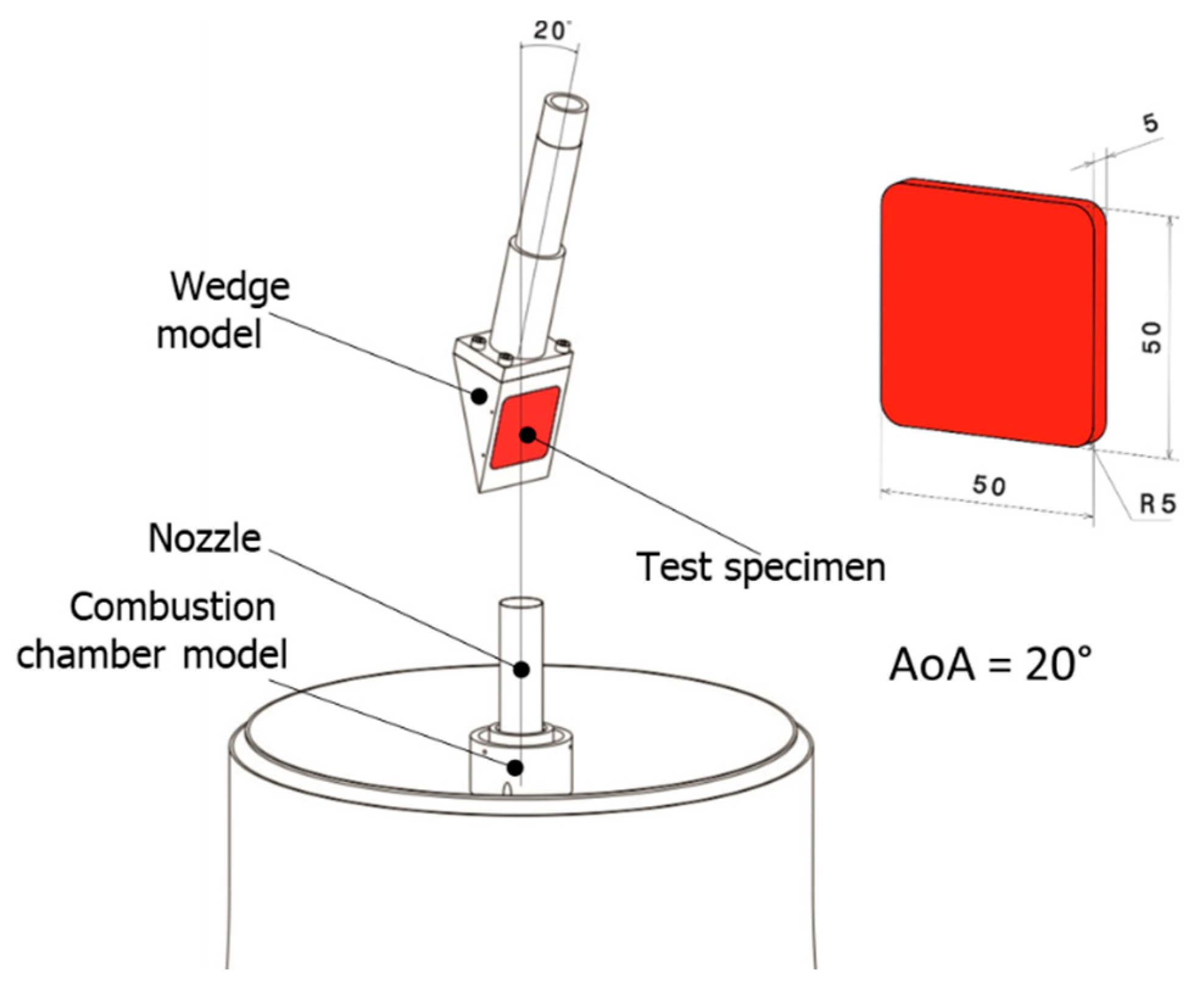
Figure 1. VMK experimental test facility arrangement.
Jcs 06 00024 g001
Figure 2. SEM images of the starting UHTCMCs at low and high magnifications.
Jcs 06 00024 g002
Figure 3. Overlap of IR-images with the locations of the sample holder for 2% Al (left) and 8% Al (right) propellants.
Jcs 06 00024 g003
Figure 4. Front surface of the UHTCMC material.
Jcs 06 00024 g004
Figure 5. Surface of a sample after VMK testing using the 2% Al propellant; (left) optical view, (right) colour-coded contour map of the same image.
Jcs 06 00024 g005
Figure 6. Surface of a sample after VMK testing using the 8% Al propellant; (left) optical view, (right) colour-coded contour map of the same image.
Jcs 06 00024 g006
Figure 7. Comparative profile of height along the vertical line of the sample exposed to a plume created with 8% Al propellant.
Jcs 06 00024 g007
Figure 8. Infrared images with marked positions taken for the temperature comparison purposes, (left) at 2% Al propellant, (right) at 8% Al propellant.
Jcs 06 00024 g008
Figure 9. Temperature data from the 2% Al propellant test measured on front and back sides of the sample; (left) results from the duration of the experiment, (right) expanded view of red shaded region.
Jcs 06 00024 g009
Figure 10. Temperature data from the 8% Al propellant test measured on front and back sides of the sample; (left) results from the duration of the experiment, (right) expanded view of red shaded region.
Jcs 06 00024 g010
Figure 11. X-ray diffraction pattern of the ablated front side of the samples.
Jcs 06 00024 g011
Figure 12. Raman spectra of the ablated front side of the sample using 2% Al based propellant.
Jcs 06 00024 g012
Figure 13. SEM images of the ablated front side of the sample obtained after using (bd) 2% Al and (eg) 8% Al propellant and (a) refers to the image location on the samples.
Jcs 06 00024 g013
Figure 14. Cross-sectional SEM/EDS mapping of the ablated region obtained after using 2 % Al propellant.
Jcs 06 00024 g014
Figure 15. Schematic highlighting the ablation of UHTCMCs with solid propellants.
Jcs 06 00024 g015
Table 1. Flow conditions in the combustion chamber.
PropellantThroat Diameter, th (mm)Pressure, p0 (bar)Temperature, T0 (K)Combustion Time (s)
2% Al11.030~2700~0.9
8% Al7.060~2900~1.3
Table 2. Measured roughness values for the surface of two samples.
UHTCMC MaterialSample #1 with 2% AlSample #2 with 8% Al
Rz vertical (avg)/µm49.649.2
Rz horizontal (avg)/µm65.964.5
Publisher’s Note: MDPI stays neutral with regard to jurisdictional claims in published maps and institutional affiliations.