1. Introduction
Composite materials are increasingly used in industrial applications as they allow components with extremely high specific strength and stiffness. For economical and qualitative aspects, a high degree of automation in the production of components is also desirable for these materials. Automated tape laying (ATL) and automated fiber placement (AFP) are the most commonly used Prepreg technologies [
1].
These two processes are especially interesting for the aerospace industry, where high tolerances are required [
2]. Thermoplastic or thermoset unidirectional (UD) Prepregs are increasingly used for the automated production of advanced high-performance composites [
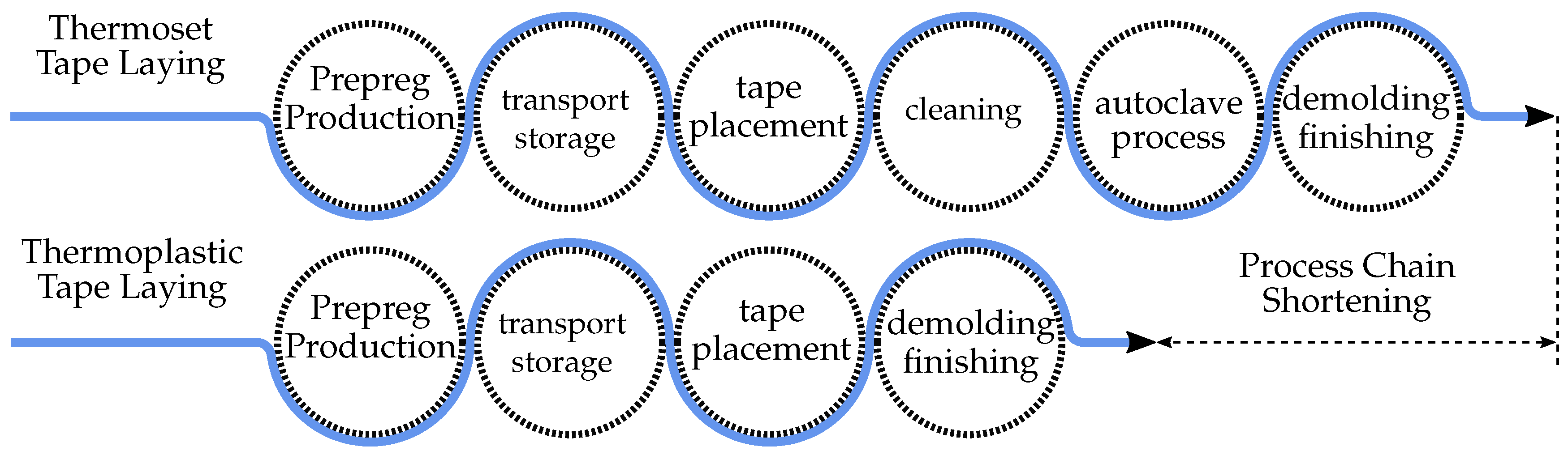
3]. The placement process with thermoset Prepregs requires a high effort on cleaning and maintenance, as well as the expensive and time-consuming hardening of the finished components in the autoclave. Compared to the thermoset tape laying process, the thermoplastic tape laying process has the potential to completely obviate the autoclave process,
Figure 1.
The thermoplastic matrix system can solidify in a few seconds, during processing, by cooling at room temperature [
1,
4]. The principle of this process is illustrated in
Figure 2. The consolidation roller applies fiber-reinforced, thermoplastic Prepreg in a defined way and presses it on the existing Prepregs. The thermoplastic matrix allows bonding, during tape deposition through heat application [
5].
Despite the advantages of thermoplastic materials, this process is not widely used in the industry. The quality of the consolidation is often still inadequate, therefore an autoclave process has to be subsequently applied which destroys the economic advantage of the process [
6]. Mechanically or thermally induced stresses lead to significant component deformation, especially in open structures [
7]. Poor adhesion to the tool due to insufficient self-adhesive force leads to a secondary effect on concave geometries (
Figure 3a). Placement on non-cylindrical surfaces can lead to some gaps [
8]. In the case of thermoset tape laying, these can be filled by hand with specially cut pieces, which is not possible with thermoplastic tape laying (
Figure 3b).
Placement of convex or concave parts with rigid consolidation roller can tilt the tape and lead to irregular compaction of the tape (
Figure 4 right).
The thermoplastic Prepregs are compacted according to the state of the art by a roller system with three different types. The first is a rigid consolidation roller that consists of a specific steel cylinder with internal cooling channels. The second consolidation roller consists of a similar basic structure and is additionally covered with a thick silicone shell to ensure shape adaptation. This method is often used in the industry. The consolidation tire as the third type is a special construction based on the basic structure of a car tire. A reinforced silicone shell is connected to a steel shaft with internal pressure. The internal pressure of the tire is adjusted and constantly regulated via inlet and outlet channels. A scientific study compared these three different consolidation rollers with each other in different aspects [
9]. It shows that the form-adaptive consolidation roller presents significant advantages over the other concepts [
10]. It considerably increases the layer contact length compared to the rigid roller and the roller with silicone cover, as can be seen in
Figure 4 on the left. Additionally, at high placement speeds, it significantly increases the layer contact time.
The rigid consolidation (a) is often used when the tool shape is flat. When the tool shape is curved, especially for concave surfaces, the flexible roller (b) can be used very well. For complex double curved surfaces, the form-adaptive roller (c) can be used most effectively, although controlling the air pressure of the rollers is a challenge. The diagram in
Figure 4 on the left, the contact time between the consolidation roller and the materials is significantly reduced at high speed. By increasing the contact time, even at low speeds, the quality of the laminate can be improved and the advantage of this process can be better displayed. The viscosity of the thermoplastic material during processing depends inversely on the process temperature. Low viscosity is required to achieve high bonding strength. Temperature and exposure time must not be too high, as degradation effects can occur which impair the mechanical properties of the bonding [
11].
An important parameter for high laminate quality is consolidation force. The force generated by the consolidation unit fills voids and gaps between the tape layers. The proportion of interfaces in direct contact increases with increasing consolidation force. At these interfaces, intramolecular adhesive forces can occur, which are decisive for interlaminar strength. Several research studies have shown that too much consolidation force has a negative influence on the adhesive strength [
5,
12]. The consolidation time, with which the layers are compressed by the consolidation unit is also an important parameter. The longer the contact time of the layer, the more connections can build up between the layers, and the higher the bonding strength [
9].
Consequently, one company (Cincinnati) has developed a Planar Consolidation Unit. The unit can increase the contact time between the material and the consolidation unit. However, this process is very slow and can only be used for planar laminates. [
13].
At the Technical University of Munich (TUM), a 4 KW diode laser is used for in situ consolidation of PEEK material. The aim of this research is to increase the laminate structure by parameter optimization in the AFP process [
14]. In further investigations, researchers tried to increase the quality of the laminates by different parameterization of the laydown speed and compaction force as well as the melting temperature [
15,
16]. AFP was widely used in the industry for several years and many publications regarding the consolidation unit are published. However, publications are mostly concerned with the materials and cooling of the consolidation unit. Recently, a research paper was published that experimentally investigated an approach to improve compaction quality in a preheated in situ compaction process by applying ultrasonic vibration. The consolidation time is also increased in this paper in order to improve the quality of the laminates [
17]. This research suggests a new principle of motion based on a consolidation roller.
2. Methodology
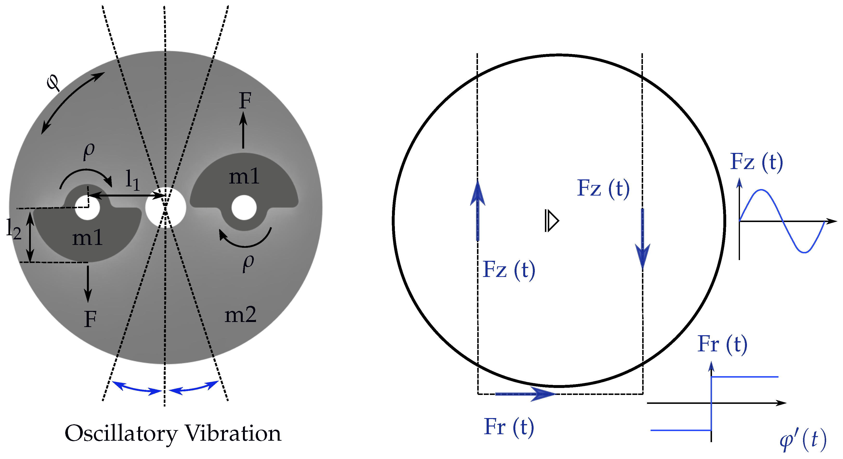
The aim of this research is to increase the laminate quality without reducing the depositing speed by keeping the same depositing parameters. This goal is achieved by generating new deposit forces on the consolidation roll. High-speed forward and reverse rotation of the consolidation roller generates new shear force vectors and increases the force duration on the laminate, as well as extending the contact time of the consolidation roller and tape at the same deposit speed. These shear forces are applied in the fiber direction and, by tensioning the fiber during laydown, the fiber waviness is eliminated. Furthermore, the compaction force of the roller remains constant over time perpendicular to the fiber direction. These additional force vectors can be generated by the generation of harmonic oscillations that are connected to the consolidation roller. While harmonic oscillations are sinusoidal, non-harmonic are all oscillations whose shape does not correspond to a sine wave [
18]. The oscillations are generated by two unbalanced masses that rotate in the same direction, but their phase is shifted by 180°, and the whole oscillator is connected to the shaft of the consolidation roller (
Figure 5 left). It is essential that the unbalanced masses are mounted rotated by 180° to each other, as in this arrangement a harmonic oscillation can be generated. If the unbalanced masses are mounted without the 180° rotation, each rotation will cause the roller to knock or pop off the tooling plate, causing the laminate surfaces to be damaged and the fibers to fail to be consolidated parallel to each other.
The consolidation roller on the AFP machine is usually compact and cannot install the unbalanced masses directly on the roller considering the mechanism movements. Furthermore, this mechanism can collide with other components. Therefore, initially, it is necessary to define a basic setting for the installation and the parameters in detail.
The position of
lever arm and
mass length are the most important parameters for the whole system. The centrifugal forces
of the unbalanced masses generate the drive torque of the roller. They are rotating force vectors and their force application points rotate additionally with the roller. The resultant force
is zero at every time, as the forces are always of equal value and apply in opposite directions. Therefore, only the effect of the forces
for the drive torque must be considered. The components of the forces
applying tangentially to the consolidation roller are exclusively responsible for the drive torque (
Figure 5 right). This component
is simply the projection of the circular motion of Fz and thus a sinusoidal oscillation. The circulating force vectors can therefore be reduced to two forces
tangentially applied to the roller with a sinusoidal shape. The rotation of the force application points also has no influence on the drive torque, as the lever arms of
always remain the same.
As the roller executes an alternating torsional vibration, it applies a time-dependent frictional force to the substrate. Depending on the direction of rotation of the roller, this changes its direction and thus its sign. Depending on the angular velocity of the roller, the following physical effects must be identified for the frictional force:
Static friction, when the angular velocity is zero.
Sliding friction, which exists above a certain angular velocity.
A transition area between static and sliding friction. Here, the stick-slip effect can occur, which is also known as jerk sliding. In this case, static and sliding friction occur alternately, causing the component to perform a sudden jerky movement.
The static frictional force is generally greater than the dynamic frictional force. The frictional force depends on the normal force and the coefficient of sliding friction .
In addition, as described above, the space required by the unbalanced masses and the oscillator extends beyond the diameter of the consolidation roller. To prevent the unbalanced masses from colliding with the other components on which the consolidation roller stands, the oscillator must be physically separated from the roller. The oscillator can be used next to the consolidation roller or on a separate shaft.
3. Imbalance Exciter—ODE Modeling
The system of the consolidation roller consists of three elements as shown in
Figure 6. These are the consolidation roll with lever arm
to the oscillating masses
and
. The consolidation roll is considered massless and borne in its center point
and
. The constellation of the elements can be described with three angles,
,
, and
. Here, the roller position is given by
, where
is measured to the horizontal through the bearing point. The rotational speed of the consolidation roll is therefore given by
.
The center of rotation of the two masses
and
is at angle
to the horizontal through the bearing center of the consolidation roll. Analogously, the center of mass of the rotational masses is determined by
and the lever arm
. Hence, the rotational speed of the oscillating masses is given by
. The angular velocities and position are known at a given time
t. In the positive and negative direction of the axes, the distance
or
, respectively, can be derived from the geometric conditions. These can be described by the transformation equations:
Physical model of the consolidation roller is based on the formulation of the centrifugal force of mass
and
. As the masses
and
are equal, it follows that
. The radius
is defined as the distance between the bearing
B and the center of mass for
and
. It follows that
and equivalently
. For simplicity, the time dependence of r(t) is omitted in the following formulations
.
The angles
and
are given respectively by
With Equations (
1) and (2) in Equation (
7), and Equations (3) and (4) in Equation (8), one obtains:
The time derivative and squaring of the Equations (
9) and (10) followed by substitution into (
5) and (6) results in:
which can be divided into the
x and
y portions. The forces at bearing point
B are therefore calculated with the equilibrium of forces:
As shown in
Figure 6 the
y-part of the bearing forces is equal to the compressive force
and the
x-portion is equal to the shear force
.
A set of parameters was chosen to simulate the behavior of the consolidation system using the derived model from Equations (
1)–(
14). The simulation should show which forces can occur in
x- and
y-direction and how the influence of
and
relates.
The following model parameters have been used for the simulation:
The first simulation covers the time behavior of forces in the
x- and
y-direction. Forces depend on the angular velocities
and
. To show the effect of
and
, each was varied in a range of
and
. The time period was chosen to be 120 s. As can be seen from the
Figure 7,
essentially influences the fundamental, and
the harmonic, oscillations.
| Model Parameter | Value | Unit | Description |
| 0–40 | U/min | (initial) value for |
| 200–900 | U/min | (initial) value for |
| m | 0.08 | kg | vibration masses and |
| l1 | 0.06 | m | length of lever arm r1 |
| l2 | 0.035 | m | length of lever arm r2 |
| 0.001 | s | timestep in simulation |
The forces acting on the system are significant for the effect of the consolidation roll. For this purpose, a combination of different
and
and
and 900 was simulated, and the largest occurring force was noted in each case is shown in
Figure 8. The simulation results show that, as the value of
increases, there is initially a rise in
and
. The maximum forces reach a high point at
. Values above
cause a slow decrease in maximum forces.
Figure 9 shows the maximum force
and
as a function of
with constant
. It can be seen that
reaches a maximum with
and
a maximum with
. Maximum forces are therefore obtained with a
. Higher values reduce the maximum forces continuously by a small amount. The optimal operating point
is mainly determined by the geometry
and
of the consolidation system.
4. Experimental Setup
The unbalanced masses can be adjusted using a shaft on the consolidation roller in a compact configuration. The illustration shows the basic structure of the test platform (
Figure 10b). The installation should provide measurement of the lateral force generated by the roller. A force sensor, which can measure in the tensile and compressive directions, is connected to a movable measuring carriage to which the roller transmits its shear force (
Figure 10a). The roller should also be able to move back and forth in a linear guide, and its pressure force on the substrate should be adjustable. The consolidation roller is mounted on a vertical linear guide which can be loaded with weights.
The main challenge in the design of the oscillator is the transfer of the drive power for the rotation of the unbalanced masses to the consolidation roller of the moving system. If the electric motor is installed directly on the moving oscillator, it is not simple to power the motor by rotating the roller. Therefore, a solution (
Figure 10b) is required which allows the unbalanced masses to be driven by an external electric motor using a mechanical coupling. The system is very similar to a planetary gear. The two rotating shafts (A) which carry the unbalanced masses, are connected to an electric motor by toothed belt. This causes the unbalanced masses to rotate, which in turn induces rotation of the shaft B and therefore of the oscillator and the roller. The toothed belt can also generate a direct rotation of the shaft B. Furthermore, coupling effects can occur, as a torsional oscillation of shaft B, in turn causes an angle change between the oscillator and the shaft of the electric motor.
The unbalanced masses should be able to rotate at a frequency of 3–8 Hz. As the transmission ratio of the selected timing belt drive is 1:1, the electric motor must be adjustable from 200–500 rpm. The moment must also be higher than the friction moment of the timing belt drive and the plain bearings.
The study evaluates how the mechanical Prepreg properties of composite materials change according to the new consolidation system. ILSS test can refer to the quality of the interlaminar bond by indicating the maximum shear stress existing between the laminate layers [
19]. The investigated laminates material is the C T50-4.0/240-T140 from SGL Group unidirectional carbon fiber reinforced polyamide 6. They are provided as a tape of 6.35 mm wide and 0.18 mm thickness. The parameters used to manufacture laminates are summarized in
Table 1.
The test configuration is according to the standard for determination of the apparent interlaminar shear strength DIN EN 2563 [
20]. Eight specimens have been prepared for each testing, and a load was applied with a constant displacement rate of 1 mm/min. The results of the interlaminar shear strength at different rotational speed of the consolidation roller, compared to those without additional rotational movement, are shown in
Figure 11. The significant positive effect of the new forces on the bonding between the different layers can be seen. By increasing the motor speed to 500 rpm, the shear strength can be improved by 6.2% compared to conventional methods. Higher speeds are not investigated in this study, as the AFP head structure for this research could operate stably up to 500 rpm.


