Article

Experimental Investigation of In-Plane Shear Behaviour of Thermoplastic Fibre-Reinforced Composites under Thermoforming Process Conditions

by
Nikita Pyatov
1,*,
Harish Karthi Natarajan
1 and
Tim A. Osswald
2
1
Continuous Production Simulation, Volkswagen AG, 38440 Wolfsburg, Germany
2
Polymer Engineering Center, Department of Mechanical Engineering, University of Wisconsin-Madison, Madison, WI 53706, USA
*
Author to whom correspondence should be addressed.
J. Compos. Sci. 2021, 5(9), 248; https://doi.org/10.3390/jcs5090248
Submission received: 26 July 2021 / Revised: 27 August 2021 / Accepted: 30 August 2021 / Published: 15 September 2021

Abstract

:
In order to meet environmental regulations and achieve resource efficiency in the series production of vehicles, recyclable polymer composites with a high strength-to-weight ratio are increasingly being used as materials for structural components. Particularly with thermoplastic fibre-reinforced polymers or organo-sheets, the advantage lies in the tailored mechanical properties of the final component by adapting the orientation of fibres based on the direction of loads. These components produced by thermoforming organo-sheets also offer a cost benefit and short cycle times. During the thermoforming process, the shear behaviour of the organo-sheet is the most dominant and determines the mechanical properties and quality of the resulting component. However, the current standard for characterising the shear behaviour of organo-sheets does not consider the strain and cooling rates inherent in the thermoforming process. This research investigates the influence of thermoforming process parameters on the shear behaviour of organo-sheets with a new methodology combining DSC and DMA experiments. During the thermoforming process, the transition of the matrix material from a molten state to a solid state is dictated by the crystallisation kinetics and their dependence on heating and cooling rates. Thus, non-isothermal DSC scans, which correspond to a temperature cycle in a thermoforming process, are used in the DSC experiments to establish the relationship between the recrystallisation temperature of the organo-sheet material and the cooling/heating rates in the thermoforming process. In order to achieve thermoforming-process-relevant cooling rates, fast scanning calorimetry (Flash DSC) is used in addition to conventional DSC measurements. DMA experiments carried out with 45° fibre orientation show that the recrystallisation temperature consequently influences the shear storage modulus of the organo-sheet. The results from DSC measurements show a shift of recrystallisation temperatures to lower temperatures as the cooling rate increases. The combined analysis of results from the DSC and DMA experiments supports the findings and shows the influence of the process temperature, cooling rate and strain rate on the recrystallisation temperature and, in turn, the shear behaviour of organo-sheets. Thus, a recommendation for establishing a new standard for characterising the shear behaviour of organo-sheets is made.

1. Introduction

Thermoplastic composites with continuous fibre reinforcements, also known as organo-sheets, are increasingly used in the automotive industry due to their excellent lightweight potential, superior mechanical properties and formability compared to conventional materials, such as aluminium and steel. The use of thermoplastic polymer in these composites also results in faster cycle times for production and recyclability for further use, unlike composites with a thermosetting polymer matrix [1,2].
Organo-sheets are available as prepreg materials, which are continuous fibre textile reinforcements impregnated with a polymer matrix. These organo-sheets could then be formed into three-dimensional shapes by forming processes. A high potential process for forming prepregs into three-dimensional shapes in the automotive industry is thermoforming [3], which involves heating the organo-sheet above the matrix melting temperature, transferring the heated organo-sheet onto the mould cavity, and forming between shaped moulds. The term thermoforming, in the context of shaping organo-sheets, is not to be confused with vacuum or pressure forming of thermoplastic sheets or films, where the main deformation mode is stretching and not bending or shear as is the case with thermoplastic matrix fabrics.
The thermoforming process is accompanied by significant mechanical and chemical changes in both the constituent phases of the composite and at their interfaces. Whereas the reinforcement experiences only mechanical changes in the form of deformations, the matrix material experiences both mechanical and chemical changes, primarily due to the temperature change. The shear behaviour of organo-sheets during thermoforming plays an important role in determining the quality of the thermoformed part. Hence, a precise understanding of the in-plane shear behaviour in the thermoforming temperature range is necessary to optimise the yarn orientation and produce a defect-free part.

1.1. Organo-Sheets

Organo-sheets are two-dimensional textiles pre-impregnated with a thermoplastic matrix material and are also known as prepregs. The textile reinforcement can be unidirectional tapes, non-crimp fabrics or woven fabrics. These organo-sheets serve as ready-made starting materials that can be formed into three-dimensional shapes through any of the forming processes. The mechanical properties of the organo-sheet largely depend upon the constituent materials, number of plies and the structure of the reinforcement.

1.2. Thermoforming

There are different types of manufacturing processes available for the large-scale production of thermoplastic composites [4,5]. Thermoforming is a manufacturing technique that involves the shaping of two-dimensional prepregs into complex three-dimensional shapes. Thermoforming is defined as a high-deformation rate process in which the thermoplastic composite material is deformed by heating it to a temperature above its melting temperature (for semi-crystalline polymers) or glass transition temperature (for amorphous polymers) [6]. Other forming processes include diaphragm forming, hydroforming and stamp forming [6]. Various undesirable defects, such as buckling, wrinkling and tear can arise during the thermoforming process as a result of non-optimal process conditions. To produce good quality parts, a thorough understanding of the thermoforming process conditions and the material behaviour during the thermoforming process is necessary.
A typical thermoforming process consists of five stages [7]:
  • Heating;
  • Transfer;
  • Forming;
  • Consolidation;
  • Ejection.
In the heating stage, the organo-sheet is heated using infra-red rays to the forming temperature, which is 20 to 40 °C above the melting temperature of the matrix material. In the transfer stage, the heated organo-sheet is transferred from the heating station to the pre-heated forming tools using a vacuum gripper or other special types of grippers. The forming tools, called moulds, are at a temperature that is much below the temperature of the heated organo-sheet, but also much above the room temperature. The moulds are then closed and the organo-sheet takes the shape of the moulding cavity. The forming stage is where the actual material processing takes place. Additionally, blank holders may be used as a part of the forming tools in order to prevent wrinkling of the organo-sheet during forming. In the consolidation stage, the formed part is allowed to cool down and solidify. The solidified part is finally ejected from the moulds through some ejection mechanism in the ejection stage. Additional trimming operations might be necessary to remove any excess material before the part is put to use or further assembly [6,7].
The temperature during the thermoforming process plays an important role in determining the formability of the organo-sheet, the resulting part quality and the resulting microstructure [8,9]. The temperature change in the organo-sheet during the five stages of the thermoforming process is schematically shown in the form of a temperature–time curve in Figure 1.
As depicted in Figure 1, the organo-sheet loses its temperature throughout the thermoforming process after the initial heating stage. During the transfer stage, the organo-sheet loses temperature in the form of heat predominantly due to convection and secondarily through conduction through contact surfaces of the transfer tool. Although the temperature drop is quite small, it has to be taken into account during the heating stage so that the organo-sheet temperature is still in the forming temperature range after the transfer stage. During the forming stage, the drop in temperature is significant due to the heat transfer between the organo-sheet and the moulds by conduction [10]. Hence the temperature of the moulds and the temperature difference between the organo-sheet and the moulds are important process parameters in determining the cooling rate of the organo-sheet. It is therefore crucial to control the cooling rate, which influences the crystallisation in the case of the semi-crystalline polymer matrix and also minimises residual stresses [9]. The formation of crystallites in the semi-crystalline polymer depends on the cooling rate—a slower cooling rate leads to excessive crystallinity, resulting in a brittle material behaviour, and a faster cooling rate results in low crystallinity. The starting temperature of crystallisation also depends on the cooling rate [11]. However, the influence of the cooling rate on the thermoforming process and the deformation behaviour has not been studied extensively. During the consolidation stage, the organo-sheet loses temperature by heat transfer through conduction, and, during the ejection stage, through convection and radiation [10].

1.3. Mechanics of Thermoforming Process

Various mechanisms of deformation and interactions in the material are involved during the thermoforming process to form the material into a three-dimensional shape. These mechanisms can be classified into inter-ply and intra-ply interactions and deformations. Inter-ply mechanisms include delamination, friction between the tool and the organo-sheet and friction between the organo-sheet plies. Intra-ply mechanisms include axial fiber strains, in-plane shear and out-of-plane bending [6,7].
In several studies, the various intra-ply deformation mechanisms were investigated independently [12,13,14], as well as combined [15], which indicated in-plane shear to be the most dominant mode of deformation during thermoforming.

2. Overview of Characterisation Methods

The experimental investigation of the shear behaviour of organo-sheets with woven reinforcements, with respect to the thermoforming process, is important as they determine the final mechanical properties of the formed part. It is therefore important to characterise the material behaviour of organo-sheets according to the conditions of the thermoforming process in order to understand the influence of process parameters on formability, and to provide input and validation data for process simulations [16]. Thermal and mechanical properties of organo-sheets and their dependence on each other are important to determine the material behaviour during the thermoforming process. The characterisation of these properties helps in determining the optimal process conditions for the thermoforming process.

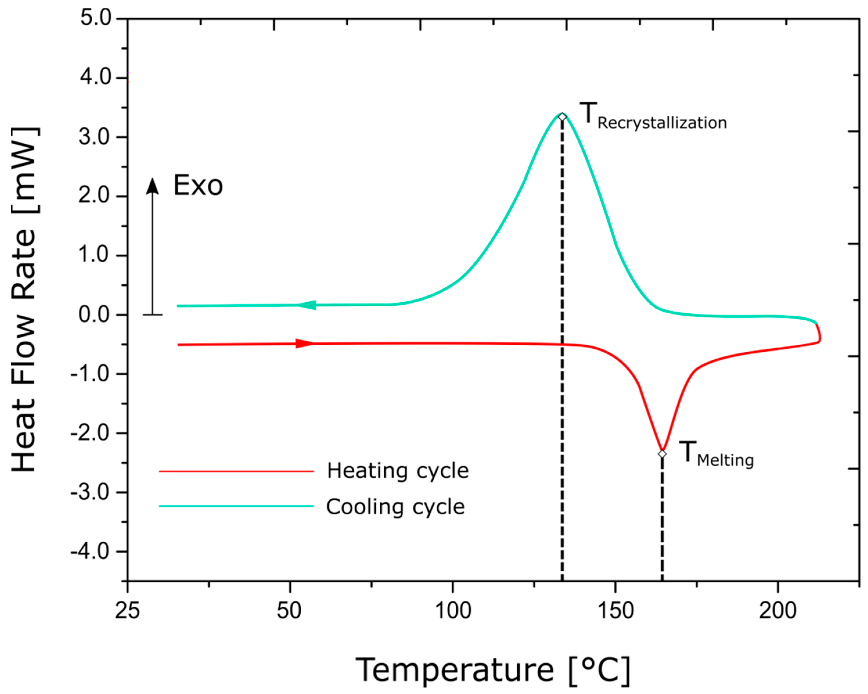
2.1. Differential Scanning Calorimetry

Differential scanning calorimetry (DSC) is an effective technique for studying the thermal properties of polymeric materials. A differential scanning calorimeter is an equipment that works on the principle of differential scanning calorimetry, which enables the measurement of different physical quantities, such as the melting temperature, glass transition temperature, crystallisation temperature and other effects involving changes in heat capacity or latent heat [17]. The heat capacity of a material is defined as the amount of heat required to raise its temperature by 1 K.
Calorimetry is based on the following relationship:
δ Q = C × Δ T = c × m × Δ T
In differential form, it can be written as
δ Q dt = Φ = C × dT dt = c × m × β
where δ Q is the heat exchanged, Δ T is the temperature change caused by heat exchange, Φ is the heat flow rate, C is the heat capacity, c = C / m is the specific heat capacity, m is the sample mass and β is the scan rate in heating or cooling [17].
At low temperatures, adiabatic calorimeters are used to measure the heat capacity precisely. However, the uncertainty of measurements increases at higher temperatures and for low conductivity materials, such as polymers. This necessitates the use of differential scanning calorimeters [17]. Modern heat flow differential scanning calorimeters based on ISO 11357-1:2016(E) operate by measuring the difference in heat flow rate into a sample crucible containing the polymer of interest, and that into a reference crucible, which is usually empty [18]. A schematic of a differential scanning calorimeter is shown in Figure 2. The heat flow rates in DSC tests can be measured as a function of temperature and/or time. DSC tests can thus determine the change in the thermal properties of polymers, with respect to the melting temperature, glass transition temperature or the recrystallisation temperature [19].
DSC is also an excellent tool for tracking the progress of crystallisation in a polymer. The crystallisation is started by nucleation and is followed by crystal growth. Upon cooling, nuclei form, causing small regions of tangled molecular chains to become ordered and aligned. The creation of crystalline structures causes an excess of energy in the form of heat, which needs to be deducted from the melt before the cooling can continue. This excess heat results in an exothermic peak in the DSC curve. The shape of this curve is directly related to the time and temperature dependency of crystallisation, which is termed as crystallisation kinetics [20].
The semi-crystalline polymer, polyamide or PA6 (nylon), is of interest in this work. PA6 consists of two crystalline structures, namely α and γ phases [4,21]. The mechanical properties of the PA6 polymer, such as the elastic modulus and tensile strength, were found to be dominated by the amount and size of spherulites in the crystalline structure of the polymer, which is directly proportional to the crystallinity of the α phase [5]. Earlier works on the crystallisation kinetics of polymers focused on isothermal DSC tests, where the sample is rapidly cooled from its melting to the crystallisation temperature and the heat that has evolved when the sample is held isothermal is measured. Isothermal crystallisation kinetics of glass-fibre-filled PA6 composites were studied in [22], which concluded that the addition of filler materials, such as fibres, influence the thermal properties of the polymers
The analysis of the thermoforming process requires thermal properties of the organo-sheet material at process-relevant cooling rates in a range greater than 10 K/s, which is not possible using conventional differential scanning calorimeters, which are limited to a maximum of approximately 2.5 K/s [23]. In addition, while isothermal crystallisation is suitable for theoretical analysis, a manufacturing process performed under dynamic conditions should be investigated with non-isothermal crystallisation [24]. Non-isothermal crystallisation kinetics of fibre-reinforced PA6 composites at high cooling rates were studied in [23] using extremely fast-operating calorimeters discussed in [17]. The shifting of the crystallisation peak to lower temperatures with increasing cooling rates was observed in [23].

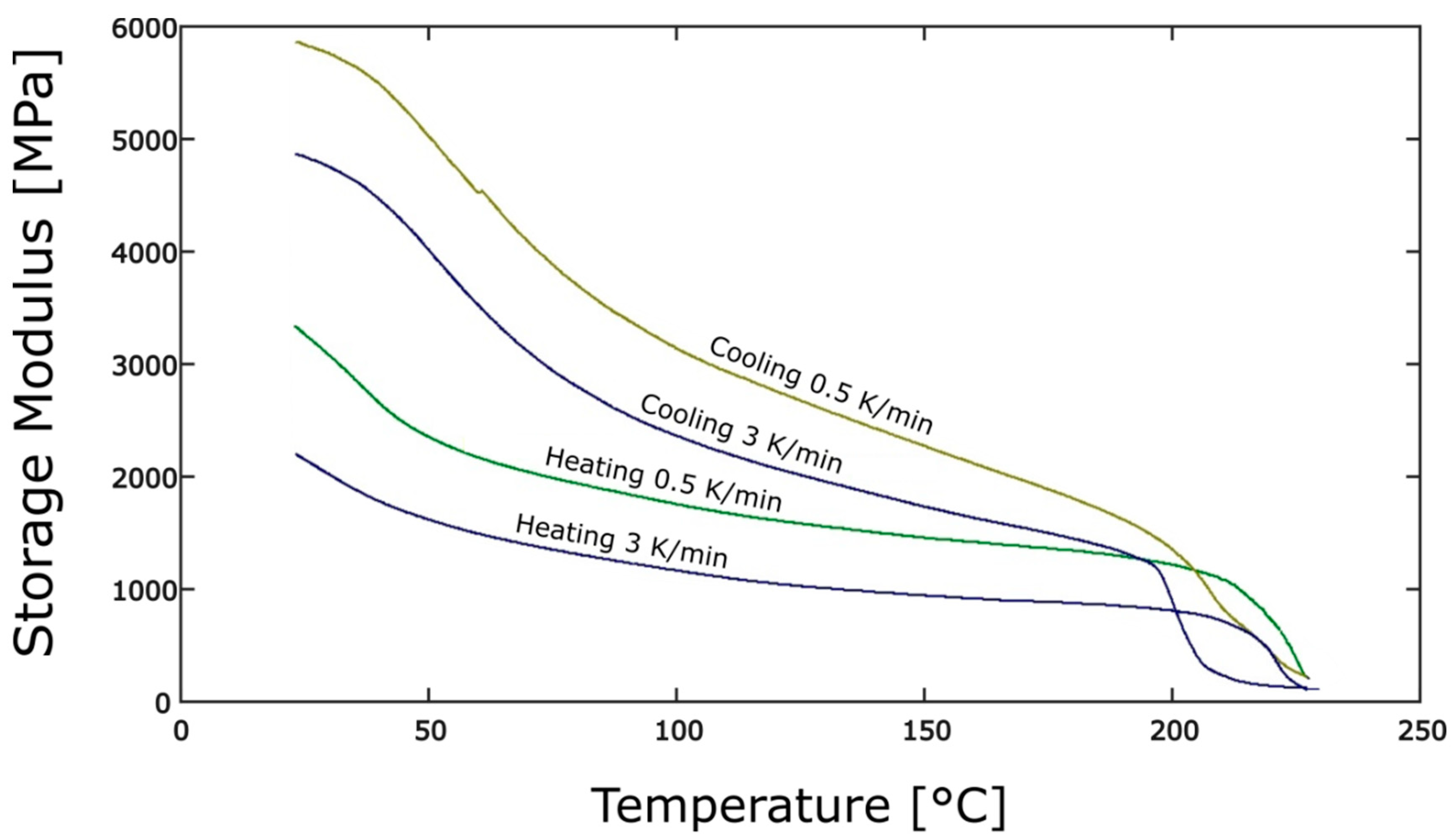
2.2. Dynamic Mechanical Analysis

In a dynamic mechanical analysis (DMA), a sinusoidal stress is applied to the test specimen as the input and the resulting deformation as strain is measured. The difference between the input stress and the output strain is measured as the phase shift δ. This shifting of the stress and strain curves is caused by viscoelastic properties of the material being tested. The output strain signal is split into an in-phase and an out-of-phase component by means of Fourier transformation, resulting in the storage modulus E’ and the loss modulus E’’, respectively [25]. The determination of the mechanical properties for plastics is detailed in ISO 6721-11:2012.
The storage modulus represents the ability of the polymer to store energy and the loss modulus represents the ability of the polymer to dissipate energy in the form of heat. The elastic response of the polymer represented by the storage modulus is conceptually similar to Young’s modulus. The advantage of DMA lies in the fact that the elastic response of the polymer can be analysed at different temperatures and frequencies using temperature and frequency sweeps.
DMA tests were a commonly used technique to characterise the small-strain viscoelastic behaviour of unfilled polymers [26,27,28] usually below their melting temperature or at a constant temperature. Later investigations used DMA tests to analyse the mechanical behaviour of fibre-reinforced polymers. It was determined in [22] that the addition of fibres in PA6 resulted in an increase in the storage modulus of PA6.
The DMA technique has also been quite effective when used to characterise the temperature dependency of the shear and bending stiffness of fibre-reinforced PA6 polymers at thermoforming process conditions in [29,30] using a dual cantilever bending fixture. The frequencies of the DMA tests were set in relation to the strain rates in the thermoforming process, and temperature scans at process-relevant temperatures at different cooling rates were studied. DMA shear tests with fibre directions at 45° to the loading directions were studied in [31], which reported an increased frequency dependence of the storage modulus of a GF/PA6 material in comparison to those tests with their loading in fibre directions. This stronger rate dependence in off-axis directions was attributed to the influence of the PA6 polymer matrix.

3. Experimental Investigation of Shear Behaviour

As discussed previously, the thermoforming process involves many process parameters, such as the tool temperature, forming temperature, strain rate and cooling rate, which must be translated to boundary conditions in the experiments. Previous studies [12,13,31,32,33,34,35,36,37] focused on the shear characterisation of continuous fibre-reinforced composites using large deformation shear tests and/or dynamic mechanical analysis. All of these studies focused on characterising the material at and around forming temperatures. Studies that have used dynamic mechanical analysis for determining the storage and loss moduli have also performed temperature sweeps in and above the melting temperature region, which is not adequate to describe the material behaviour in the entire forming temperature range. Furthermore, the process-relevant cooling rates, which have a significant effect on shear behaviour by influencing the recrystallisation temperature, were not considered in previous studies.
The primary objective of this work is to experimentally investigate the in-plane shear behaviour of the organo-sheet material while also considering its boundary conditions during the thermoforming process. As a result of the complexity in the process conditions involved in the thermoforming process, no test methods or test standards exist currently for an overall characterisation of the shear behaviour. In this work, a two-test method to consider the overall boundary conditions during thermoforming is proposed based on existing individual methods in the literature. Since thermoforming is a non-isothermal process, the dependence of shear behaviour on cooling rates is investigated using dynamic mechanical analysis, where the shear behaviour is obtained as storage modulus values. The DMA tests, especially, are conducted with reverse temperature sweeps in order to account for the change in recrystallisation temperatures with different cooling rates. In addition, the process-relevant cooling rates and their influence on the recrystallisation temperature are investigated using fast scanning calorimetry (Flash DSC) following a previous study in [23]. All of the individual experiments are analysed separately in the following sections and the correlations between results from the individual experiments are discussed.

3.1. Material and Specimen Preparation

The details of the GF/PA6 material used for the experimental investigations in this work are shown in Table 1. The organo-sheet material received from the supplier was cut into smaller rectangular strips using water jet cutting (WJC) process for easier handling. Since the PA6 matrix of the organo-sheet is hygroscopic in nature [38], and to avoid any discrepancy in the measurement of the material properties, the organo-sheet was subject to thermal conditioning to remove the excess moisture content absorbed during the WJC process. Thermal conditioning was achieved by drying the organo-sheet strips in a vacuum oven at 80 °C for 5 days. The organo-sheet strips were stored in a container with standard atmosphere between the time period after they were subjected to thermal conditioning and when they were about to be tested according to ISO 291:2008(E).

3.2. Differential Scanning Calorimetry

Non-isothermal DSC scans are used in this work to investigate the effect of heating and cooling rates on melting and recrystallisation temperatures, respectively. This behaviour is important because the kinetics of crystallisation have a significant influence on the forming process. During thermoforming process, the transition of the matrix material from molten state to solid state is dictated by the crystallisation kinetics and their dependence on heating and cooling rates, which define a crucial limit for defect-free forming [23].

3.2.1. Design of Experiments

Two test methods were used for the study, namely the conventional DSC tests and the Flash DSC tests. Organo-sheets with a single ply were used for all DSC tests.
Conventional DSC tests allow heating and cooling rates up to a maximum of 10 K/s due to a high value of signal time constant compared to a smaller signal time constant in Flash DSC [18,39]. In order to account for the process-relevant cooling rates in the range greater than 10 K/s [23], Flash DSC tests using extremely fast-operating calorimeters discussed in [17] were performed. These methods covered a wide range of cooling rates, as shown in Table 2. The conventional DSC tests covered slow cooling rates between 1 and 5 K/min, whereas Flash DSC tests covered the fast-cooling rates between 5 and 25 K/s.

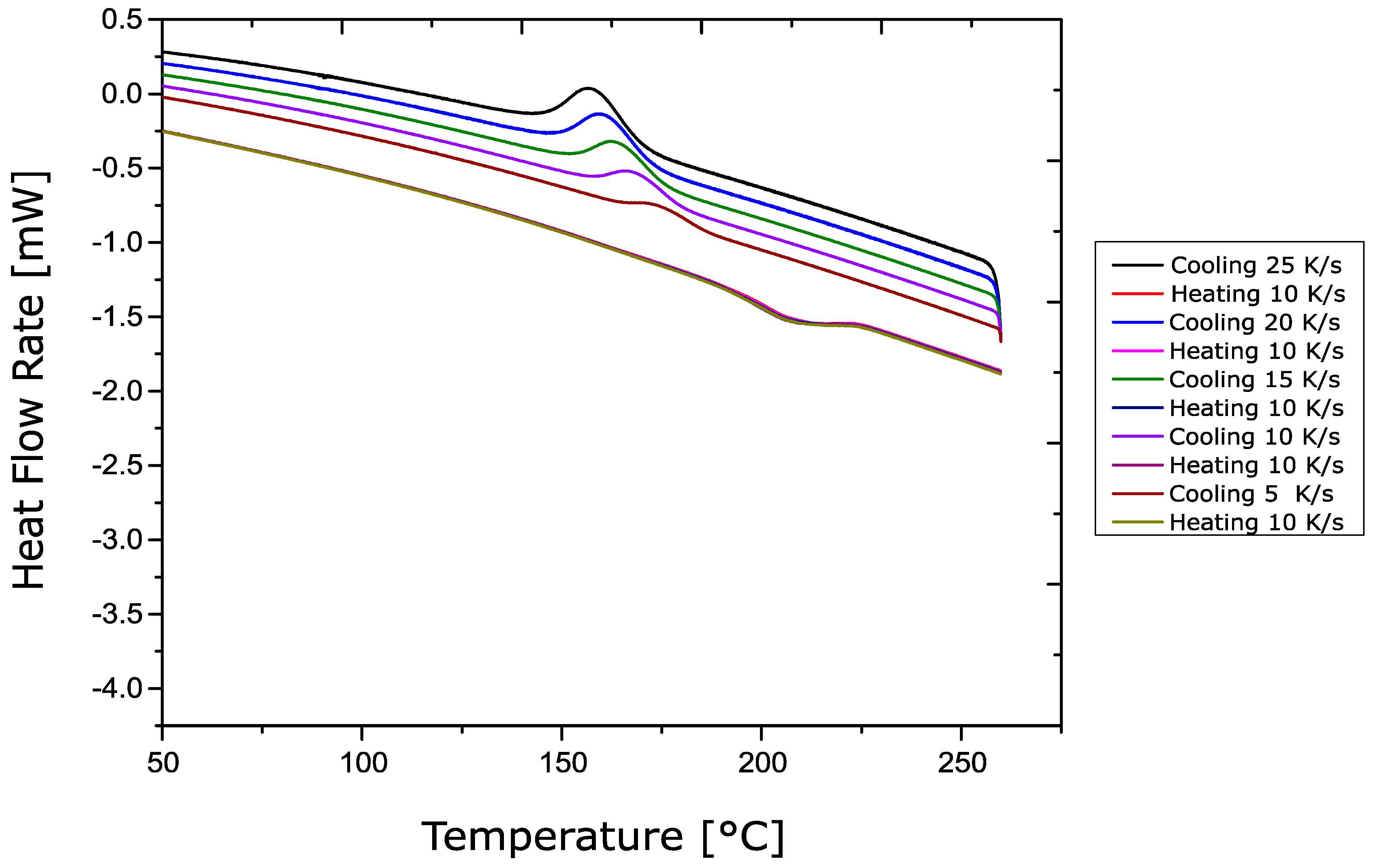
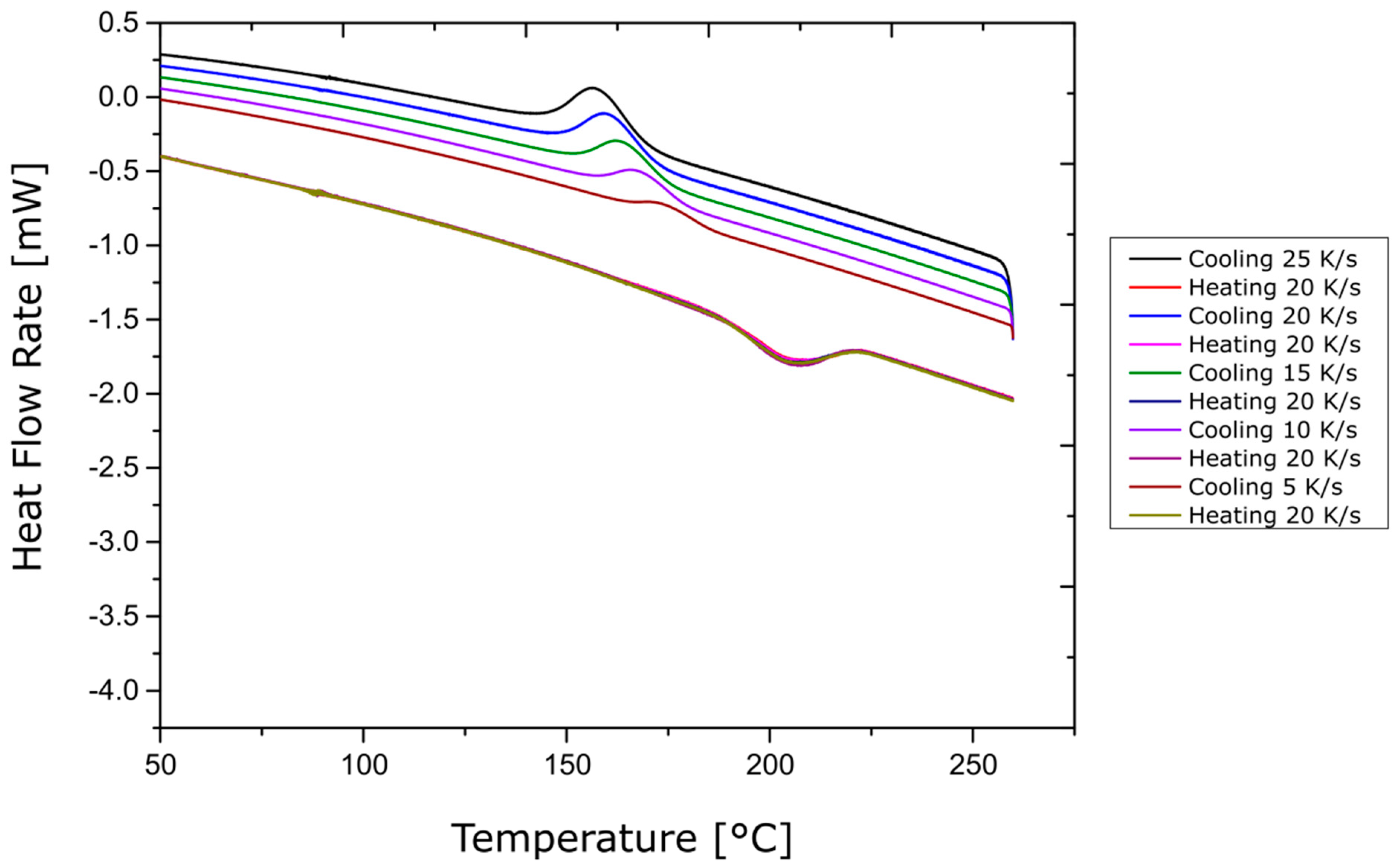
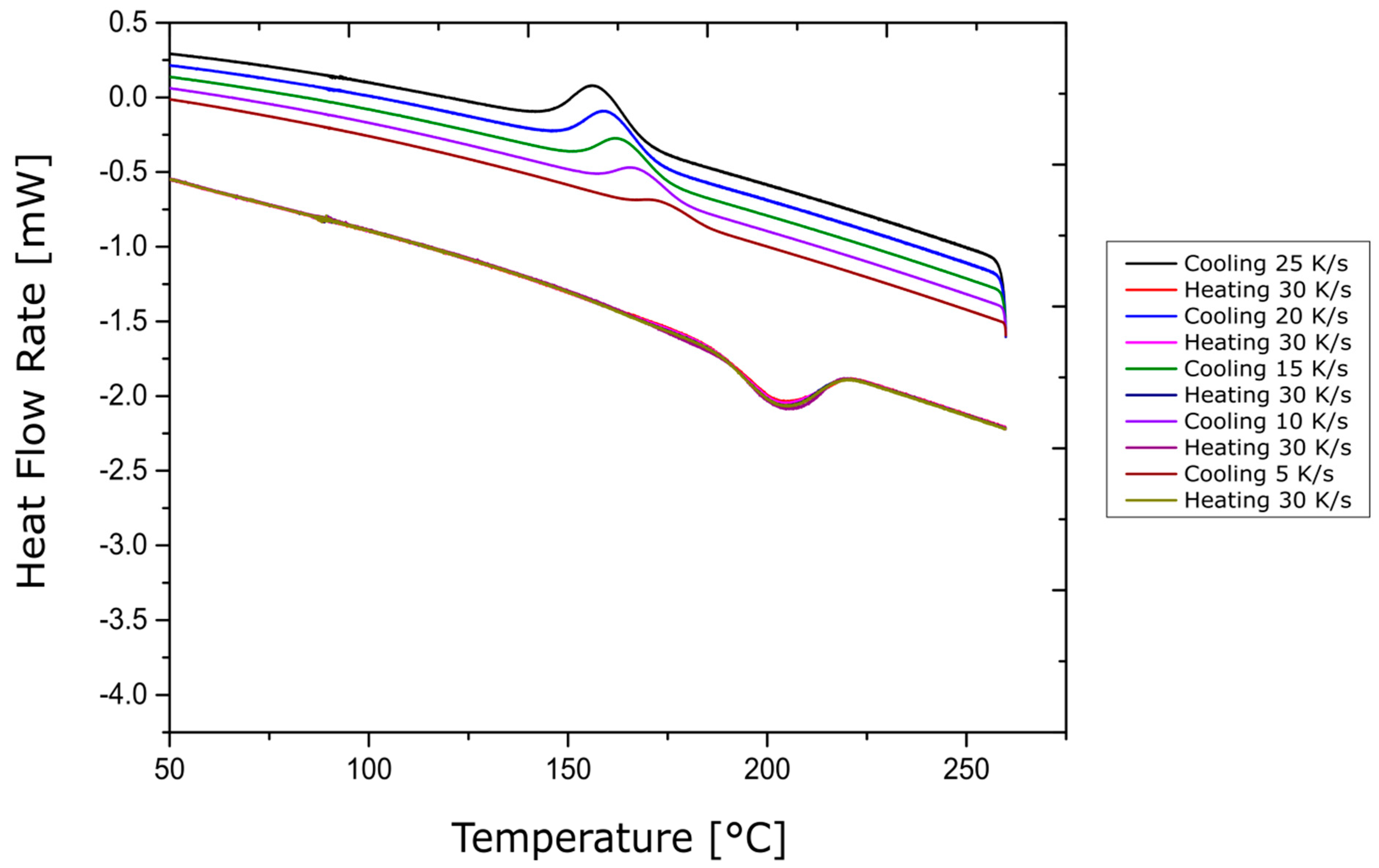
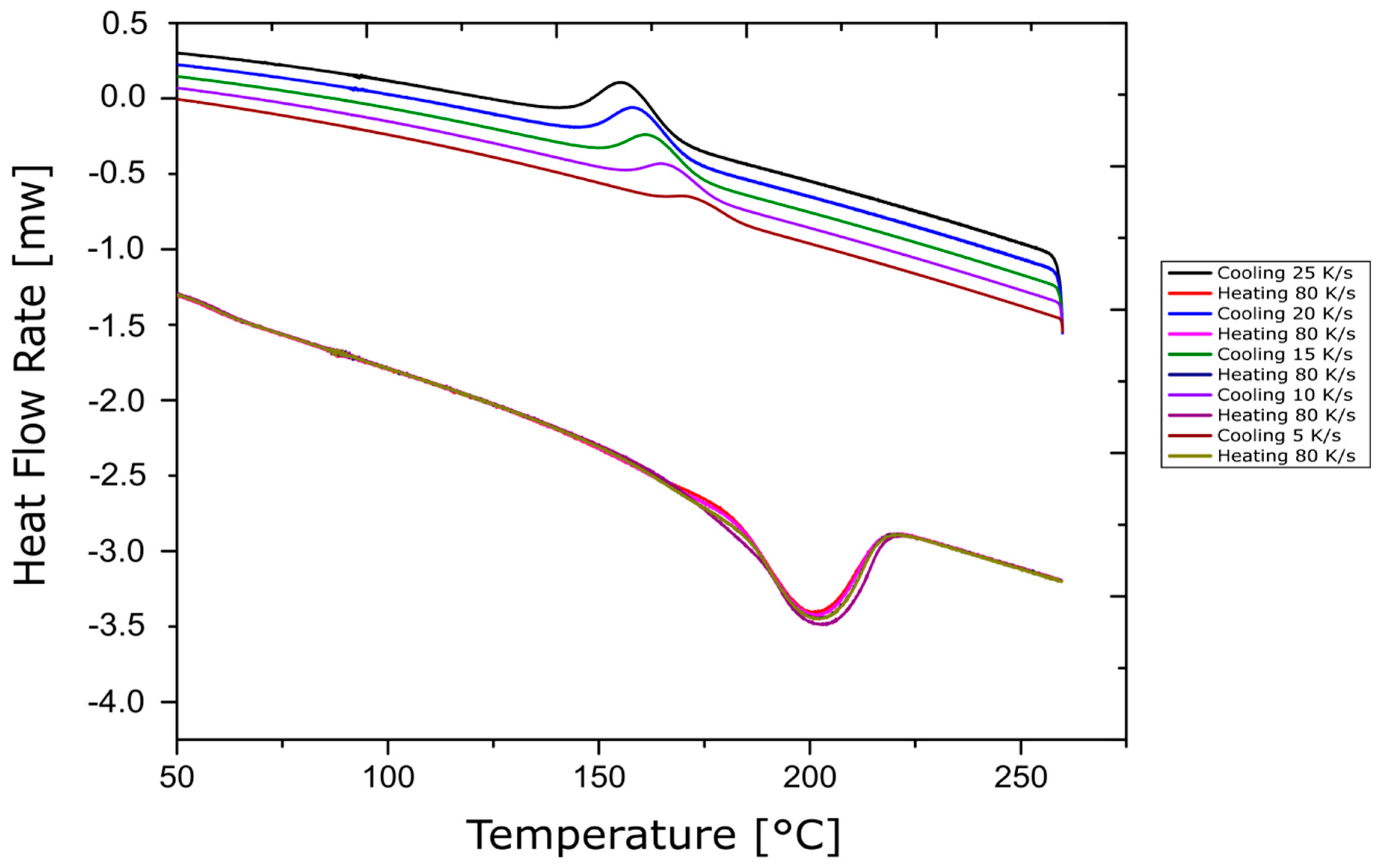
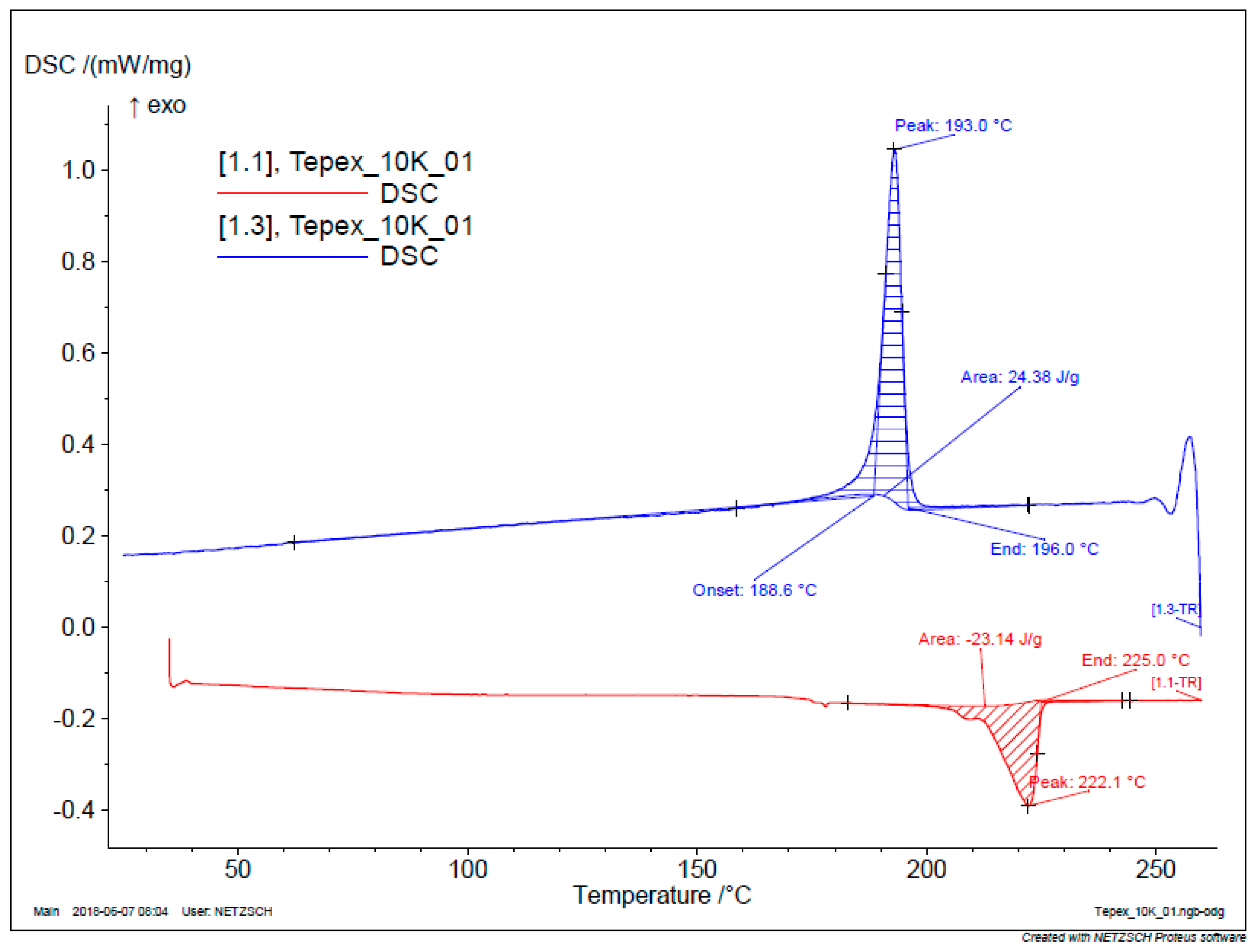
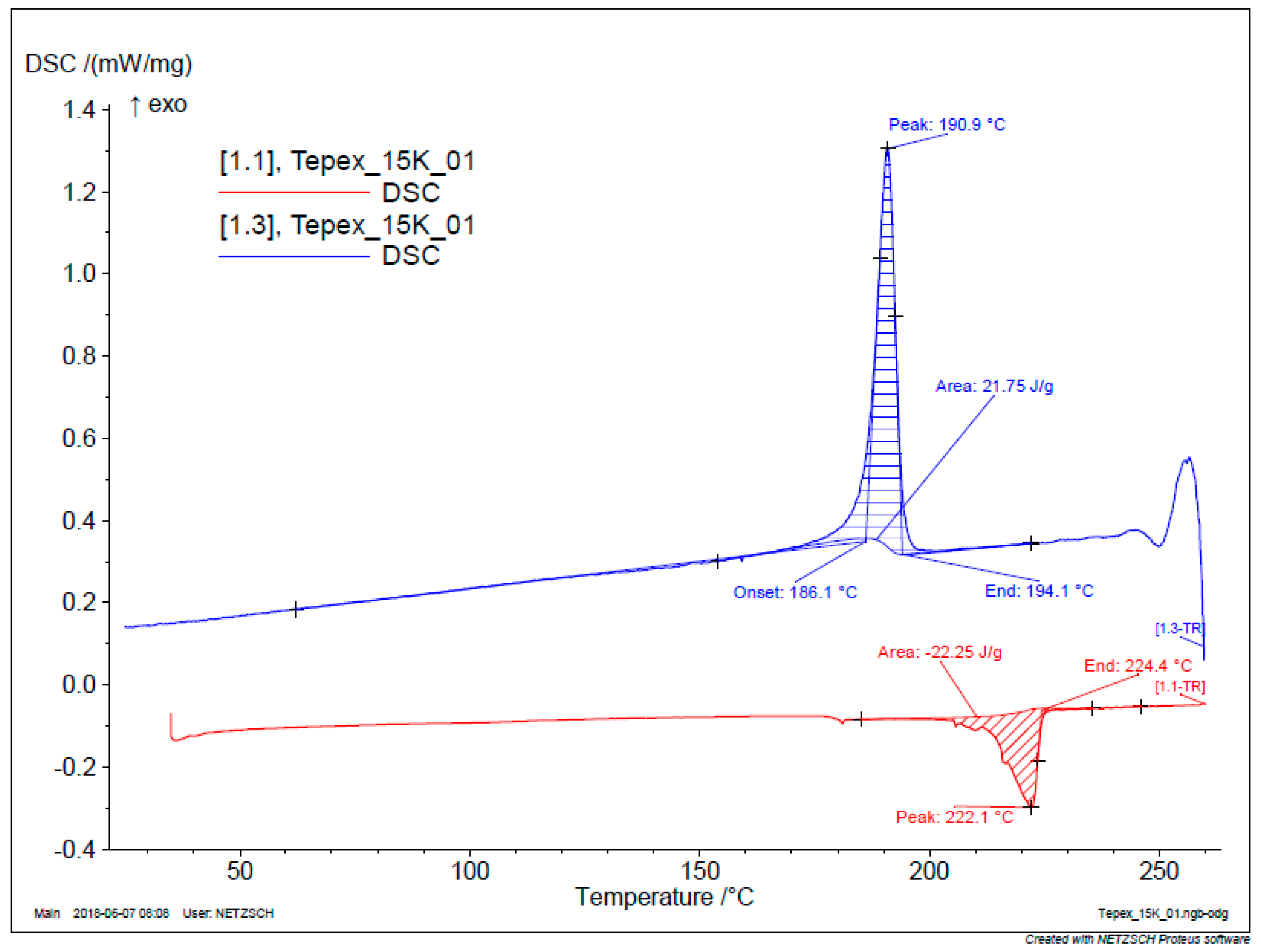
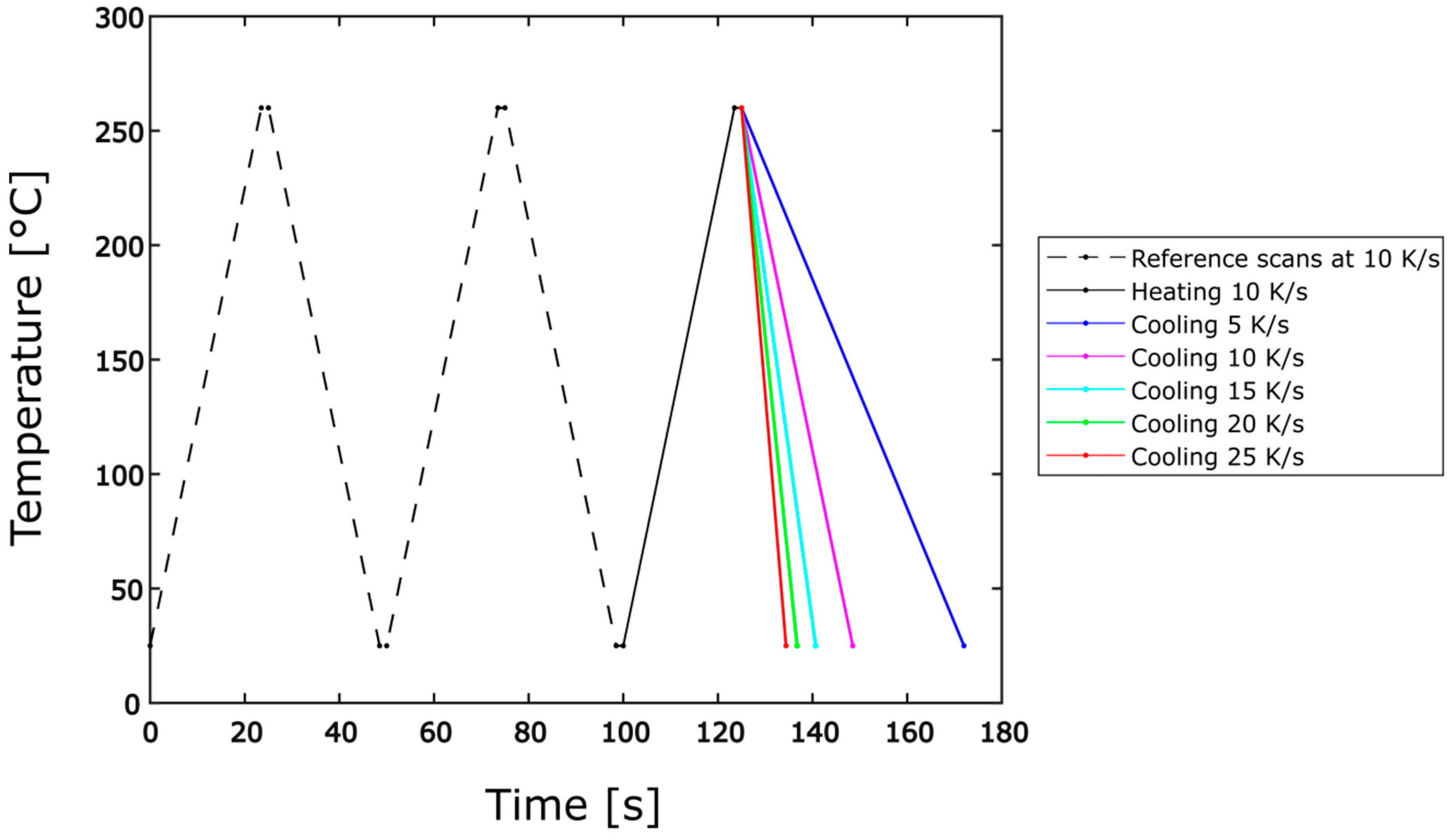
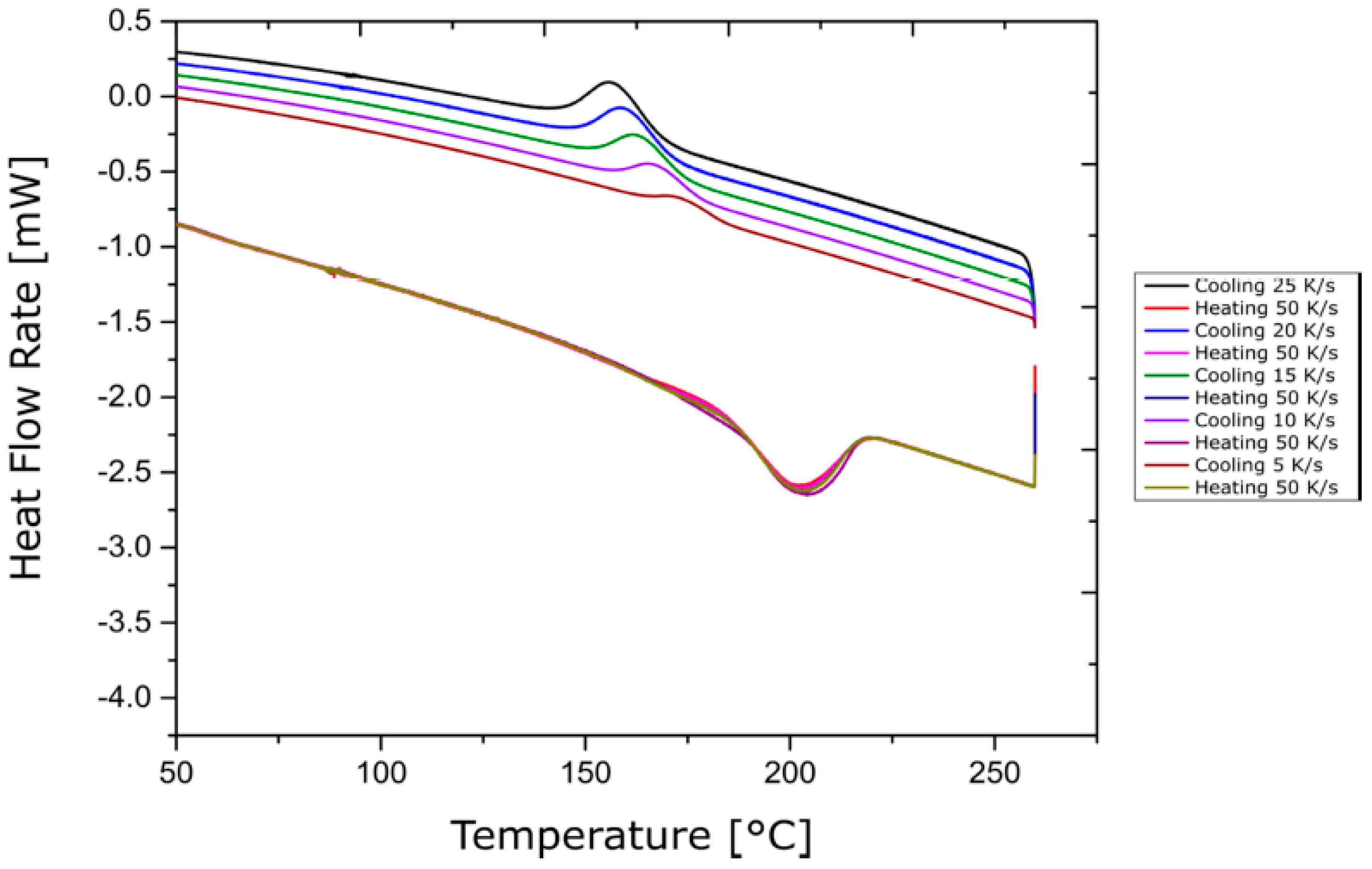
3.2.2. Flash DSC Experiments

The Flash DSC experiments were carried out using the Mettler-Toledo Flash DSC 1 equipment. It works on the same principle as conventional DSC equipment discussed in Section 2.1., but allows for higher heating and cooling rates due its very short signal time constant in an order less than 1 millisecond [39]. The measurement was facilitated by the UFS 1 MultiSTAR sensor, which is a microchip embedded in a ceramic support. The UFS 1 sensor, which has a maximum operating temperature of 450 °C, is based on MEMS (Micro-Electro-Mechanical Systems) technology and consists of two separate calorimeters for sample and reference similar to that of conventional DSC equipment. Each calorimeter consists of a crucible coated with aluminium in order to achieve a homogeneous temperature profile. The temperature in the crucible area was measured by means of eight thermocouples.
High heating and cooling rates in the order of 1000 K/s can be achieved in the crucible due to both its low heat capacity and the temperature difference between the crucible and the environment [39]. During the experiments, the samples were initially cut from the organo-sheet strip using a punch, and then were reduced in size with a precision knife. The samples were cut from areas not too close to the edges of the strip to eliminate any possible chances of fibre loss during the WJC process and to have a sample that is the representation of the actual fibre volume in the composite (47%). The samples of adequate size were then prepared via observation through the microscope available in the Flash DSC 1. The sample was then placed in the sample furnace with the help of the thread hair in the UFS 1 sensor. The microscopic image of the nanogram-sized DSC sample on the sample furnace is shown in Figure 3.
The temperature profile used for the experiments consisted of two cycles of alternate heating and cooling at 10 K/s between 25 °C and 260 °C as reference scans, followed by heating from 25 °C to 260 °C at one of the several heating rates between 2 and 100 K/s. After this, individual cooling rates of 5, 10, 15, 20 and 25 K/s were applied for each experiment. This last cycle of heating and cooling will be referred to as measurement scan in this work. The experiments were repeated for three samples at each cooling rate. A sample test plan with the reference and measurement scans for the measurement heating rate of 10 K/s is shown in Figure 4.

3.2.3. Conventional DSC Experiments

Conventional DSC tests were carried out using Netzsch DSC 204 F1 Phoenix equipment. Although different crucible types are available in this DSC equipment, aluminium crucibles were used to facilitate comparison of the results from the Flash DSC tests. The cooling rates can be controlled with liquid-nitrogen-based cooling equipment [18]. A test plan similar to the Flash DSC was used with two reference scans at 10 K/min for heating and cooling followed by a heating scan and a cooling scan at different rates.
The sample size in conventional DSC is in the order of milligrams, which is larger than the nanogram samples used for Flash DSC tests. The conditioned samples were prepared using a punching machine to small circular shapes of around 4 mm diameter in order to fit the sample crucible. Since conventional DSC tests have been described to great extent already in literatures, only a brief overview of these tests is documented in this work.

3.3. Dynamic Mechanical Analysis

In this work, dynamic mechanical analysis is used to study the dependency of shear behaviour on temperature, strain rate and cooling rate. DMA as a characterisation method for fibre-reinforced composites has been investigated in a few literatures based on the performance of DMA methods in polymer characterisation. Whereas [40,41] investigated the correlation of DMA tests with conventional mechanical tests, [28] focused on the temperature and strain rate dependency of bending behaviour of UD tapes. However, the cases were limited to quasistatic isothermal tests. Recent literatures have focused on extending the DMA method as a possible characterisation technique for organo-sheets during thermoforming process. In particular, [29,30] analysed the temperature dependency of shear and bending stiffness of UD tapes, as well as textile-reinforced polymers during thermoforming.

3.3.1. Design of Experiments

The DMA experiments in this work are to be carried out using Netzsch DMA 242 E Artemis equipment. Since the objective is to investigate the in-plane shear behaviour, the organo-sheet material is planned to be characterised at a fibre direction of 45° to the axis of the load application. The material behaviour in the 0/90° fibre directions is dominated by the strength of the fibres, and hence testing at 45° fibre direction would also give a realistic estimate of the combined material behaviour of the fibre and matrix material. The characterisation is to be carried out non-isothermally, with heating and cooling rates of 0.5, 3 and 5 K/min by means of a liquid nitrogen cooling system, which also avoids polymer degradation [25]. Though the equipment has a specified cooling rate range of 0.01 to 20 K/min, this range is not possible for all the test set-ups and dynamic measurements.
The test frequency in the DMA tests can be used to investigate the effect of strain rate on shear behaviour during the thermoforming process. The 242 E Artemis machine has a maximum amplitude of 240 µm and it takes one-fourth of a cycle for the machine to reach this maximum amplitude. Thus, a frequency of 10 Hz corresponds to a realistic punch velocity of 10 mm/s during the actual thermoforming process, as explained in [29]. Accordingly, five frequencies of 1, 5, 10, 15 and 20 Hz are proposed to be investigated. A wide range of temperature between 25 °C and 260 °C is necessary for the temperature sweeps in order to investigate the shear behaviour in the entire thermoforming process chain between the heating and ejection stages, and also to facilitate comparison with the DSC tests. The proposed test plan for the DMA shear test is shown in Table 3.

3.3.2. DMA Experiments

Organo-sheets with a single ply were used for all DMA tests. The organo-sheet material was cut into recommended tensile specimen sizes of 25.4 × 6.1 mm at 45° fibre direction using water jet cutting, and the specimens were subjected to thermal conditioning, as discussed in the beginning of this chapter. The shear tests were carried out using a tensile testing set-up shown in Figure 5 (left).
In the preliminary investigations, the specimens failed during the tests, resulting in unrealistic values of storage modulus. This might be due to the small size of the specimens and the relative size of the yarns to the specimen. Additionally, the number of yarns crossing in the specimen was very low (one or two), which does not provide enough strength to hold the specimen together, even at such small amplitude. The next possible alternative for dynamic measurements was the dual cantilever test set-up shown in Figure 5 (right), which facilitates the measurement of material properties by applying a perpendicular bending load at the centre of the specimen. The assumption was that the perpendicular load might not cause the specimen to break apart, as in the case of tensile fixture. In addition, the material properties in both shear and bending tests are measured in directions other than the fibre directions and hence are not dominated by the fibres. The feasibility of this test was evaluated using specimens of size 21 × 10.5 mm approximately with a 45° fibre orientation. While the specimen did not fail during the test, the DMA machine became unstable and the experiment stopped at around 240 °C during the heating cycle. This difficulty of testing at temperature around and above the melting temperature was also reported in [28], where this instability is attributed to the lack of reactivity of the DMA machine when the material is in molten configuration. However, these instability issues were not encountered in [30]. It was decided to proceed with dual cantilever tests but reduce the maximum temperature to 230 °C in order to avoid the instability issues. This change in temperature sweep range is assumed to have no impact on the material characterisation, as it was reported in [29] that the storage modulus curves of interest flatten out to a constant value above the melting temperature.
The dual cantilever test also replicates a thermoforming process, where the fixed ends of the organo-sheet are corresponding to the blankholder forces and the application of bending load is corresponding to the load application by the punch in the forming stage. Due to the limitations of the DMA machine, the 15 Hz frequency was not possible, and so the next nearest frequency of 16.66 Hz was chosen. Thus, the proposed test plan was changed during the experiment phase and is shown in Table 4.
All the experiments were carried out with the settings shown in Table 5. In all experiments, the specimen was tightened in the dual cantilever fixture with a torque of 25 cNm to facilitate uniform measuring conditions and ensure repeatability of the experiments.

4. Experimental Results

4.1. Differential Scanning Calorimetry
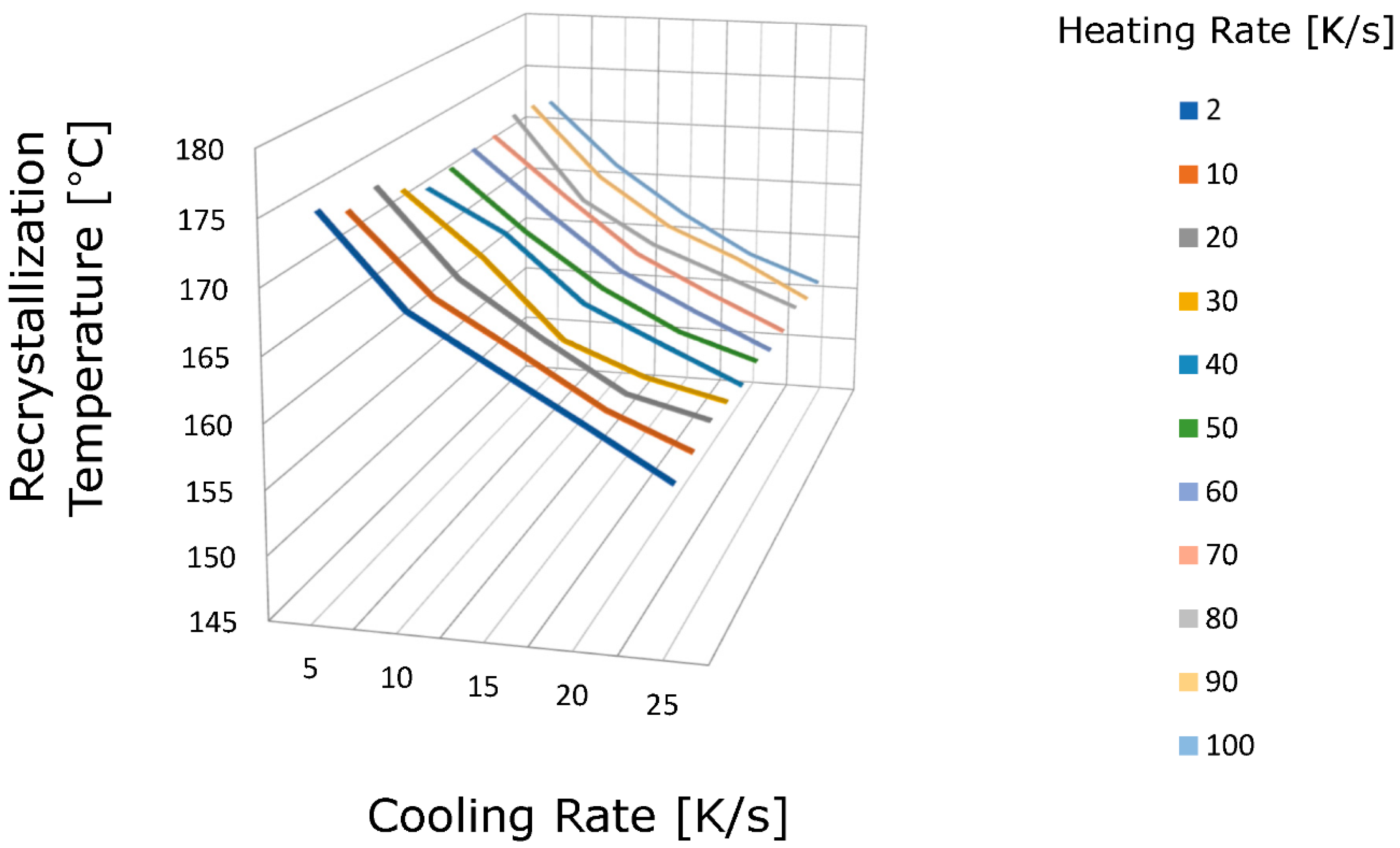
4.1.1. Flash DSC

The Flash DSC sample after an experiment is shown in Figure 6. The heat flow rate versus temperature data were obtained for all of the samples and the average curves were plotted. The labels that helped in the interpretation of the DSC curves are shown in Figure 7. All of the plots are presented in the same format as shown in Figure 7. The melting and recrystallisation temperatures in DSC tests are obtained as endothermic and exothermic peaks, respectively. The DSC curves for heating rates of 50 K/s and 100 K/s are shown in Figure 8 and Figure 9, respectively. The other experimental flash DSC curves are attached in Appendix A.
It can be observed from Figure 8 and Figure 9 and the figures in Appendix A that the melting temperature and recrystallisation temperature of the organo-sheet material does not change with the change in heating rates. However, the change in the recrystallisation temperature with the cooling rate is significant.
However, it was also observed from the DSC curves that the melting temperatures from the flash DSC experiments were in the range of approximately 205 °C, which is around 15 °C less than the melting temperature prescribed in the manufacturer’s material datasheet attached in Appendix A. This can be interpreted as a result of the difference arising due to the measurement of the melting temperature in different scan cycles. In order to verify this behaviour, a second round of Flash DSC experiments was conducted at the Polymer Engineering Center (PEC) at the University of Wisconsin-Madison, USA using the Netzsch DSC 214 Polyma equipment. The results of these experiments are attached in Appendix B.
The melting temperature from these tests in the range of 222 °C conforms closely to the melting temperature specified by the manufacturer. It is to be noted that, in this case, only one measurement scan was taken without any reference scan. This might imply that the difference in melting temperatures between different DSC tests vary with the measurement cycle in which they were measured. Further Flash DSC tests must be carried out in order to analyse this effect. Since, the focus of this work is on establishing the relationships between crystallisation kinetics and heating/cooling rates, and not on determining exact values, this observed difference in melting temperatures does not affect our study. In addition, the results from PEC further validate this study by showing a similar shift of recrystallisation temperatures to lower temperatures as the cooling rate increases. It can also be verified from the results that the melting temperature of the organo-sheet material varies only negligibly with the change in heating rates, but significantly with the change in cooling rates.
From Figure 8 and Figure 9, it can also be observed that the recrystallisation peaks shift to a lower temperature with increasing cooling rates, which is in conformance with previous research on a unidirectional carbon-fibre-reinforced tape with a PA6 matrix in [23]. This can be explained by both the rate of crystallisation, which is zero at the equilibrium melting temperature because the thermodynamic driving force for crystallisation is zero at this point, and the increase in the driving force with decreasing temperature to values below the melting temperature [42]. The same effect was observed in [43], where the crystallisation curves became broader as the temperature increased, which reflected a lower crystallisation rate.
The change in recrystallisation temperature with the cooling rate at different heating rates is shown in Figure 10. Further, Figure 11 shows the change in the recrystallisation temperature with cooling rates averaged over all of the heating rates, with error bars indicating the upper and lower limits of the recrystallisation temperature.

4.1.2. Conventional DSC

From the results of the conventional DSC tests on the organo-sheet material, it was observed that the melting temperature does not change for different heating rates and that the recrystallisation temperature shifts to lower temperatures with increasing cooling rates. For brevity, only the recrystallisation temperatures for cooling rates averaged at different heating rates are presented in Table 6.

4.1.3. Comparison of Results

From both of the DSC tests, it is known that the heating rate does not affect the melting temperature. To study the overall effect of cooling rates on the recrystallisation temperature over the wide range of cooling rates investigated, the results from the Flash DSC tests and conventional DSC tests are compared. In order to facilitate the comparison between the results from both the tests, two measures of the recrystallisation temperature are used: recrystallisation onset temperature and recrystallisation peak temperature. The recrystallisation onset temperature, which marks the initiation of recrystallisation in the material during the cooling cycle, is determined from the DSC results by marking the temperature where the recrystallisation peak starts to form. The recrystallisation peak temperature is the temperature corresponding to the peak value of the exothermic heat flow rate in the DSC results. These temperatures are the same as the temperatures tabulated in Table 6.
A comparison of the onset and peak temperatures of recrystallisation from conventional DSC and Flash DSC experiments for different cooling rates are shown in Figure 12. To bridge the gap between the range of cooling rates investigated in both the DSC methods, and to have an accurate comparison, a few additional cooling rates were also investigated until the limits of the DSC equipment for conventional DSC experiments (0.1667, 0.33 K/s) and Flash DSC experiments (0.5, 1, 1.5, 2 K/s) were reached. These additional experiments showed the same dependency of the recrystallisation temperature on the cooling rate.
It can be observed from Figure 12 that the peak recrystallisation temperature curves from both of the tests show an almost linear dependence on the cooling rate in the entire range, and that they could be approximated with a single function. Thus, the two DSC tests can be said to be in good agreement with each other. The onset recrystallisation temperature curves from both of the tests are, however, offset from each other, unlike the peak temperature curves.
The onset and peak temperatures in the Flash DSC tests are offset by a larger amount compared to those from the conventional DSC tests. This shift in the onset recrystallisation temperature to higher temperatures can be attributed to the larger specimen size of the Flash DSC sample relative to the sample crucible, as observed from Figure 3, and can be explained by the fact that the nucleation may be enhanced by the large relative surface area of the Flash DSC sample.

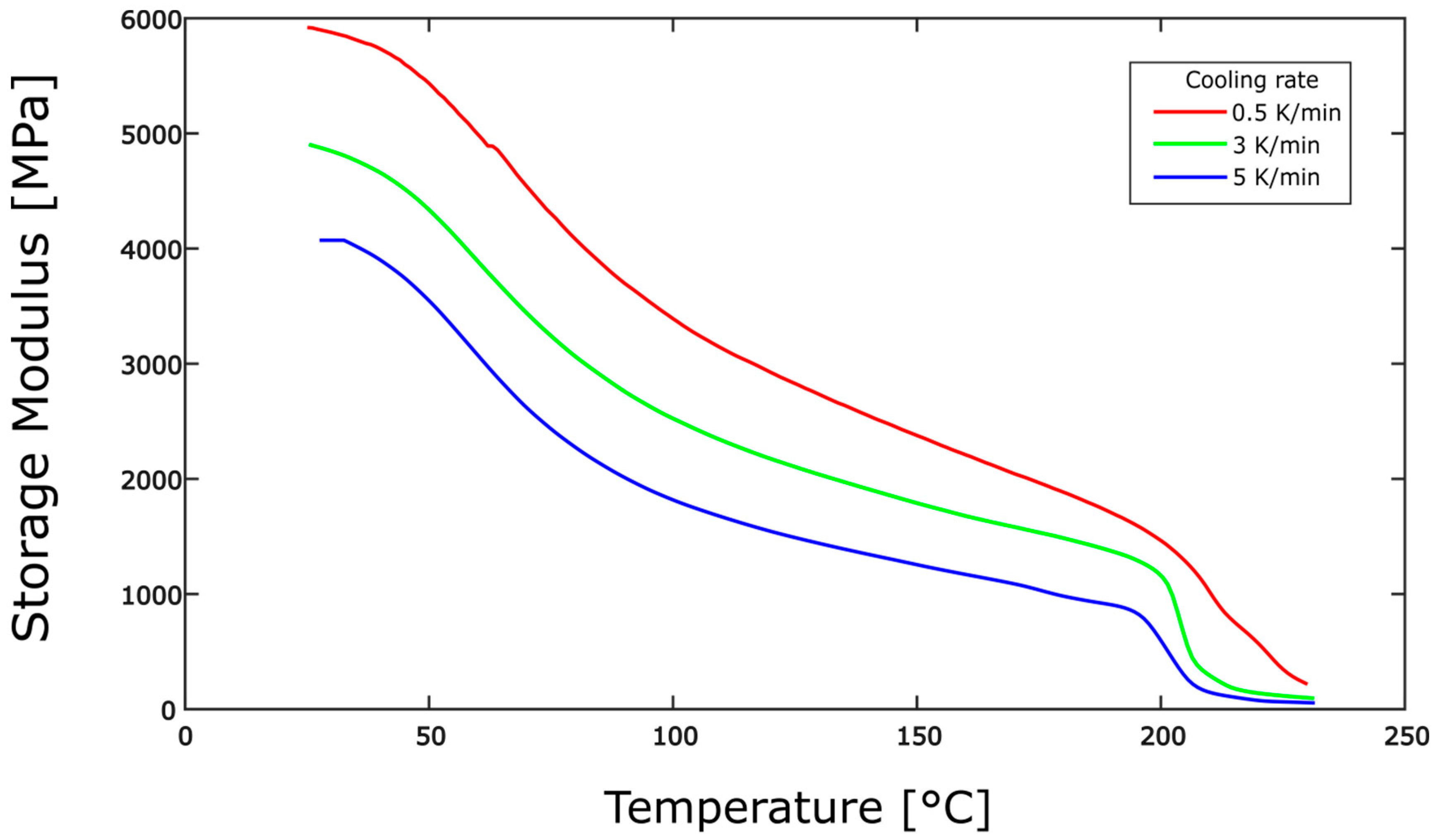
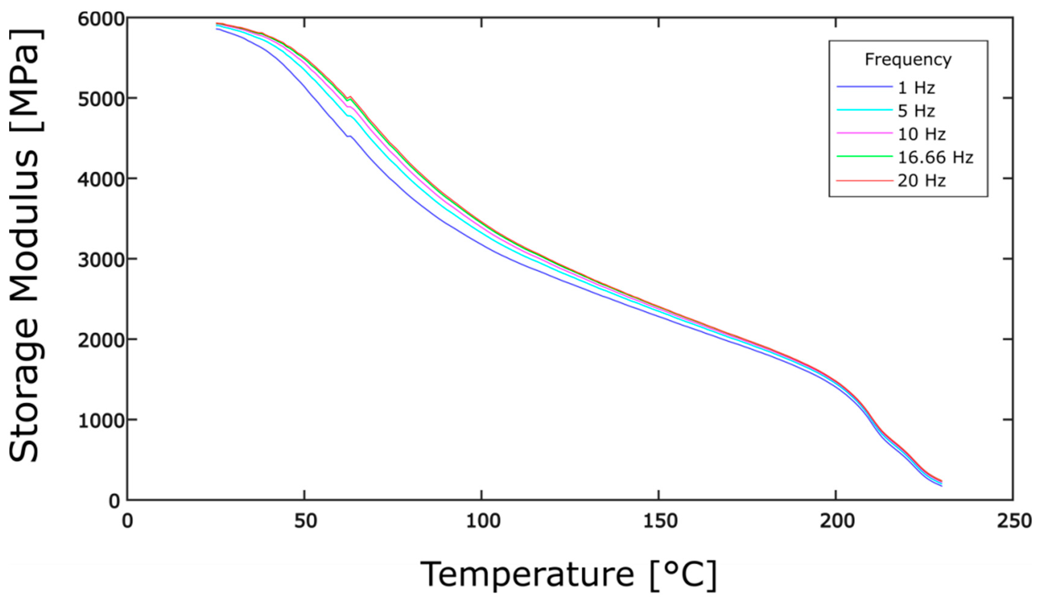
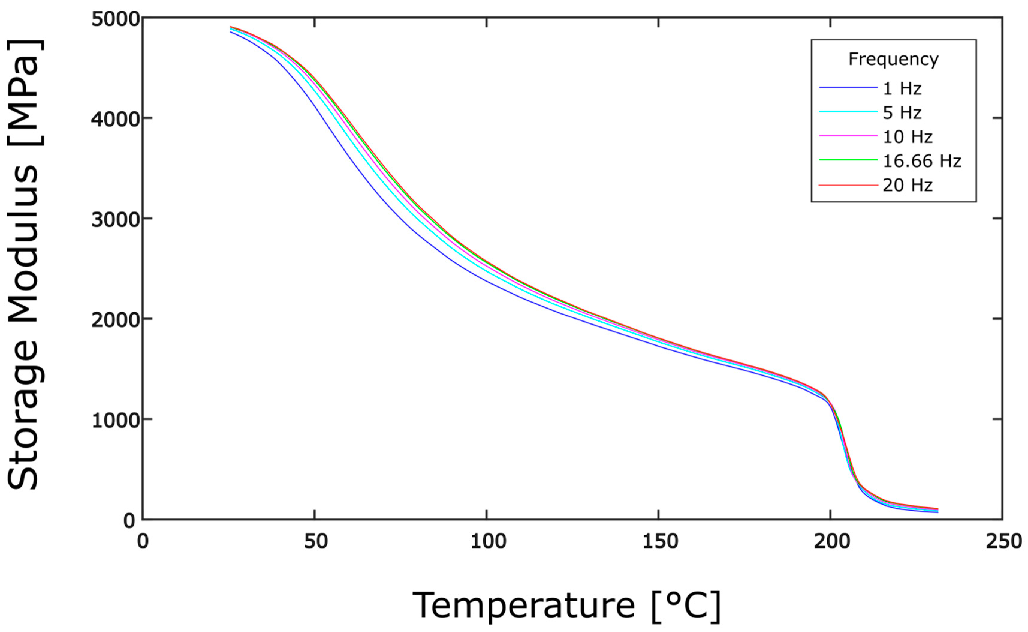
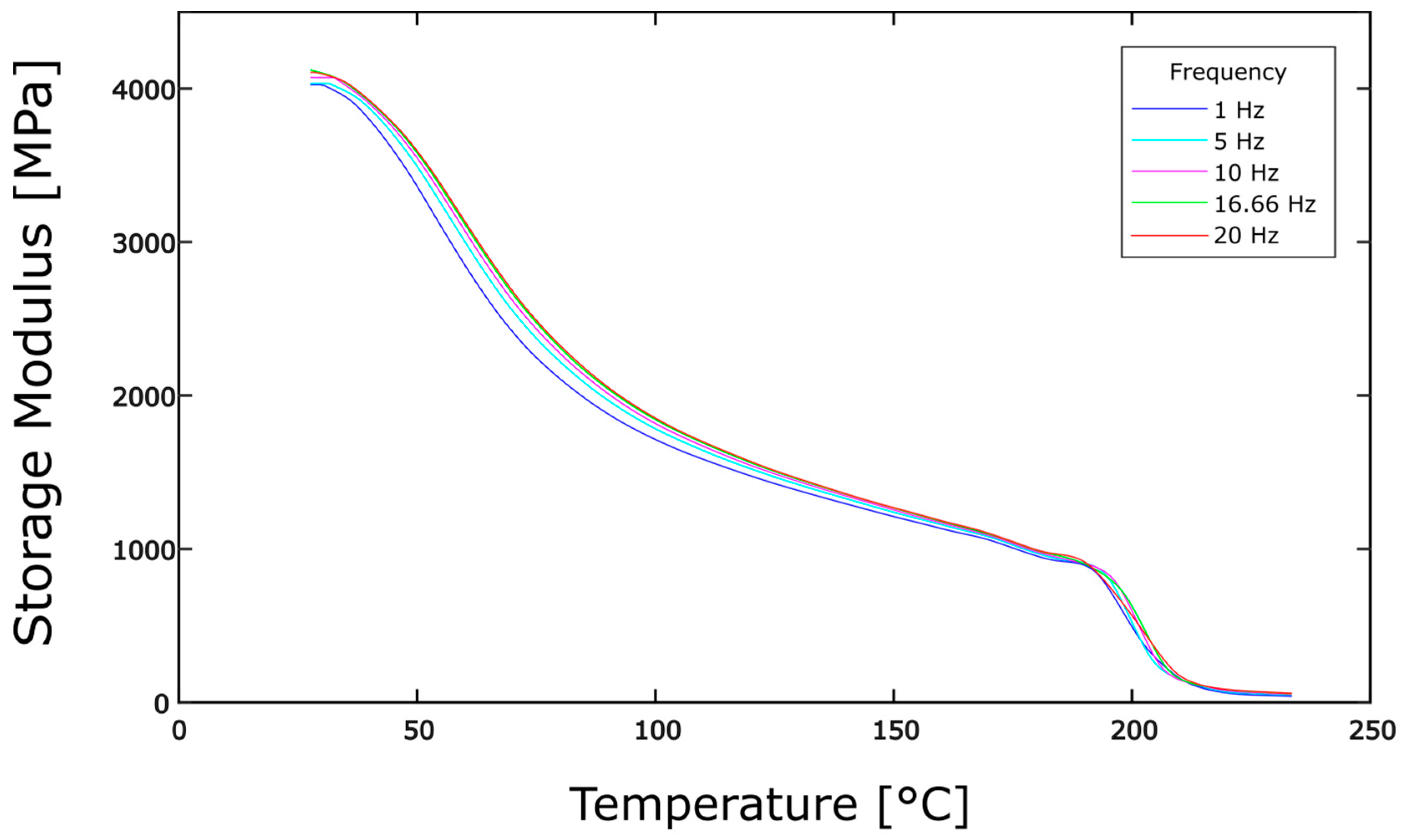
4.2. Dynamic Mechanical Analysis

The DMA specimens after the dual cantilever tests are shown in Figure 13. The results of the experiments were post-processed using Proteus analysis and evaluation software. The DMA tests for the three samples in all of the cases were highly repeatable, and therefore results from one sample per experiment were considered for further analysis.
The results obtained included the storage modulus (E’), loss modulus (E”) and the damping ratio (tan δ). All of the results were analysed, which conformed to the expected values, but the discussion here is only limited to the results based on storage modulus measurements, which relate to the elastic stiffness (here shear stiffness) of the material. In the following discussions, the storage modulus and shear modulus will be used interchangeably, since the storage modulus at 45° fibre orientation corresponds to the shear storage modulus [29]. Selected results from the experiments are presented in this section.
The temperature dependency of the storage modulus for the heating/cooling rates of 0.5 and 3 K/min for the frequency of 10 Hz obtained from the DMA experiments is shown in Figure 14.
From Figure 14, it is apparent that the shear modulus changes throughout the temperature sweeps in heating and cooling. In addition, the dependency of the shear modulus with the temperature varies with changes in heating and cooling rates. In particular, during the cooling cycle at 3 K/min, a sudden increase in shear modulus is observed at a temperature of around 200 °C. From the results of the conventional DSC tests shown in Table 6, this is approximately equal to the recrystallisation temperature observed at the cooling rate of 3 K/min, which is equal to 199.2 °C. It is possible that the crystallisation causes this sudden increase in shear modulus. However, the 0.5 K/min does not show a similar increase in shear modulus at the recrystallisation temperature. It can also be observed that the shear modulus at room temperature after the cooling cycle is higher than the initial shear modulus at room temperature in both of the cases. This can be assumed to be the effect of degree of crystallinity of the organo-sheet material.
From this point, the discussion is limited to the behaviour of the organo-sheet during cooling as it is of primary interest during the thermoforming process. The temperature dependency of the storage modulus for cooling rates of 0.5, 3 and 5 K/min for a frequency of 10 Hz is shown in Figure 15.
It can be observed that the shear modulus values increase with a decrease in temperature at all of the cooling rates, and that they are shifted to higher values with slower cooling rates. This same behaviour is also observed at other frequencies with other parameters constant. The temperature dependency of the storage modulus for cooling rates of 0.5, 3 and 5 K/min for a frequency of 20 Hz is shown in Figure 16. The sudden increase in shear modulus values is also present at all of the frequencies at temperatures of around 200 °C for cooling rates of 3 and 5 K/min. The dependence of the shear modulus on the strain rate is investigated using the storage modulus curves obtained at different frequencies. The temperature dependency of the storage modulus at different frequencies for cooling rates of 0.5, 3 and 5 K/min is shown in the figures Figure 17, Figure 18 and Figure 19, respectively.
It could be observed from Figure 17, Figure 18 and Figure 19 that the shear modulus curves shift to higher values with an increase in frequency (strain rate). However, the difference in shear modulus values is only in the order of 100 MPa with a change in frequency that is less than the difference in shear modulus values with cooling rates that are in the order of 1000 MPa. This may possibly imply that the change in cooling rates have much more of an influence on the shear behaviour of organo-sheets compared to the influence of strain rates.

4.3. Analysis and Discussion of Experimental Investigation Results

The experimental investigations on the in-plane shear behaviour were carried out using a comprehensive test method proposed in this work exclusively for the thermoforming process. This included three different sets of individual experiments on organo-sheets, with a total of five test series, namely Flash DSC tests, conventional DSC tests and DMA tests using dual cantilever fixtures.
Based on the experimental results, the dependence of the shear behaviour on different process parameters in the thermoforming process, such as the temperature, strain rate and cooling rate, were investigated. The interdependence of the process parameters on each other was also investigated.
The combined investigations of DMA and DSC tests have given various new insights on the dependence of shear behaviour with the temperature and cooling rate. The temperature was found to be the most important parameter that influences the shear behaviour. The influence of strain rates was found to be significant only at temperatures of around 220–260 °C, which are defined as forming temperatures for the investigated organo-sheet material by the manufacturer. The shear modulus values were found to be higher than the initial values at room temperature after a heating–cooling cycle in the DMA experiments. A sudden increase in the shear modulus in DMA experiments was observed at temperatures around the recrystallisation temperature determined by the DSC tests. Further investigations on the shear behaviour in large deformations should be performed in order to accurately characterise the dependence of the shear behaviour of organo-sheets on different process parameters in the thermoforming process. All of the experimental results in this paper suggest that a robust testing method for characterising the shear behaviour of organo-sheets for the thermoforming process is required in order to take into account all of the process parameters during the thermoforming process.

5. Summary and Outlook

This work focused on analysing the shear behaviour of a continuous fibre-reinforced thermoplastic prepreg material experimentally, with respect to the temperature and cooling rate during the thermoforming process.
The proposed experiments were carried out for a glass fibre-reinforced composite with a polyamide 6 matrix. The dependence of shear behaviour on the temperature, strain rate and cooling rate were analysed for this organo-sheet material using these experiments. The relationship between recrystallisation temperatures and cooling rates was determined through DSC experiments. With an increase in cooling rates, the shifting of the recrystallisation temperature to lower values was observed. With DMA experiments, the variation in the shear modulus, with respect to the temperature at different cooling rates, was analysed. During cooling, a sudden increase in the shear modulus at recrystallisation temperatures determined by the DSC experiments was observed. A temperature cycle consisting of a heating and cooling cycle before the tests at isothermal temperatures was used to capture the effect of recrystallisation on shear behaviour. While this research work used a single-ply organo-sheet for the experiments, future research shall expand this to organo-sheets with multiple plies and investigate how additional factors, such as the shear between plies, play a role in determining shear behaviour. Based on the analysis of the experimental results from this proposed test method to investigate the shear behaviour, the need for a robust testing equipment to evaluate all of the parameters influencing the shear behaviour was established.

Author Contributions

Conceptualization, N.P. and H.K.N.; methodology, N.P. and H.K.N.; validation, N.P. and H.K.N.; formal analysis, N.P. and H.K.N.; investigation, N.P. and H.K.N.; resources, N.P.; data curation, N.P. and H.K.N.; writing—original draft preparation, H.K.N.; writing—review and editing, N.P., H.K.N. and T.A.O.; visualization, N.P. and H.K.N.; supervision, T.A.O.; project administration, N.P.; funding acquisition, N.P. All authors have read and agreed to the published version of the manuscript.

Funding

This research received no external funding.

Data Availability Statement

The data presented in this study are available on request from the corresponding author.

Conflicts of Interest

The authors declare no conflict of interest.

Appendix A

The results of the Flash DSC experiments are presented here for the heating rates of 2, 10, 20, 30, 40, 60, 70, 80 and 90 K/s.
Figure A1. Heat flow rate vs. temperature plot for heating rate of 2 K/s.
Jcs 05 00248 g0a1
Figure A2. Heat flow rate vs. temperature plot for heating rate of 10 K/s.
Jcs 05 00248 g0a2
Figure A3. Heat flow rate vs. temperature plot for heating rate of 20 K/s.
Jcs 05 00248 g0a3
Figure A4. Heat flow rate vs. temperature plot for heating rate of 30 K/s.
Jcs 05 00248 g0a4
Figure A5. Heat flow rate vs. temperature plot for heating rate of 40 K/s.
Jcs 05 00248 g0a5
Figure A6. Heat flow rate vs. temperature plot for heating rate of 60 K/s.
Jcs 05 00248 g0a6
Figure A7. Heat flow rate vs. temperature plot for heating rate of 70 K/s.
Jcs 05 00248 g0a7
Figure A8. Heat flow rate vs. temperature plot for heating rate of 80 K/s.
Jcs 05 00248 g0a8
Figure A9. Heat flow rate vs. temperature plot for heating rate of 90 K/s.
Jcs 05 00248 g0a9

Appendix B

The Flash DSC experiment results conducted for the TEPEX 102-RG600(x)-47% organo-sheet material using the Netzsch DSC 214 Polyma at the Polymer Engineering Center at the University of Wisconsin-Madison, USA are shown below for heating and cooling rates of 5, 10, 15, 20 and 25 K/s.
Figure A10. Heat flow rate vs. temperature plot for heating and cooling rates of 5 K/s.
Jcs 05 00248 g0a10
Figure A11. Heat flow rate vs. temperature plot for heating and cooling rates of 10 K/s.
Jcs 05 00248 g0a11
Figure A12. Heat flow rate vs. temperature plot for heating and cooling rates of 15 K/s.
Jcs 05 00248 g0a12
Figure A13. Heat flow rate vs. temperature plot for heating and cooling rates of 20 K/s.
Jcs 05 00248 g0a13
Figure A14. Heat flow rate vs. temperature plot for heating and cooling rates of 25 K/s.
Jcs 05 00248 g0a14

References

  1. Verrey, J.; Wakeman, M.D.; Michaud, V.; Månson, J.-A.E. Manufacturing Cost Comparison of Thermoplastic and Thermoset RTM for an Automotive Floor Pan. Compos. Part Appl. Sci. Manuf. 2006, 37, 9–22. [Google Scholar] [CrossRef]
  2. Fuchs, E.; Field, F.; Roth, R.; Kirchain, R. Strategic Materials Selection in the Automobile Body: Economic Opportunities for Polymer Composite Design. Compos. Sci. Technol. 2008, 68, 1989–2002. [Google Scholar] [CrossRef]
  3. Haanappel, S.P.; ten Thije, R.H.W.; Sachs, U.; Rietman, B.; Akkerman, R. Formability Analyses of Uni-Directional and Textile Reinforced Thermoplastics. Compos. Part Appl. Sci. Manuf. 2014, 56, 80–92. [Google Scholar] [CrossRef]
  4. Kyotani, M.; Mitsuhashi, S. Studies on Crystalline Forms of Nylon 6. II. Crystallization from the Melt. J. Polym. Sci. Part-2 Polym. Phys. 1972, 10, 1497–1508. [Google Scholar] [CrossRef]
  5. Cartledge, H.C.Y.; Baillie, C.A. Studies of Microstructural and Mechanical Properties of Nylon/glass Composite Part I The Effect of Thermal Processing on Crystallinity, Transcrystallinity and Crystal Phases. J. Mater. Sci. 1999, 34, 13. [Google Scholar]
  6. Bhattacharyya, D. (Ed.) Composite Sheet Forming; Composite Materials Series; Elsevier: Amsterdam, The Netherlands; New York, NY, USA, 1997. [Google Scholar]
  7. Ropers, S. Bending Behavior of Thermoplastic Composite Sheets: Viscoelasticity and Temperature Dependency in the Draping Process; AutoUni-Schriftenreihe; Springer Fachmedien GmbH: Wiesbaden, Germany, 2017. [Google Scholar]
  8. Lessard, H.; Lebrun, G.; Benkaddour, A.; Pham, X.-T. Influence of Process Parameters on the Thermostamping of a [0/90] 12 Carbon/polyether Ether Ketone Laminate. Compos. Part Appl. Sci. Manuf. 2015, 70, 59–68. [Google Scholar] [CrossRef]
  9. Guzman-Maldonado, E.; Hamila, N.; Naouar, N.; Moulin, G.; Boisse, P. Simulation of Thermoplastic Prepreg Thermoforming Based on a Visco-Hyperelastic Model and a Thermal Homogenization. Mater. Des. 2016, 93, 431–442. [Google Scholar] [CrossRef]
  10. Kugele, D.; Rausch, J.; Müller, P.; Kärger, L.; Henning, F. Temperature Distribution in Thickness Direction of Thermoplastic Laminates during Thermoforming. In Proceedings of the International Conference on Automotive Composites (ICAutoC 2016), Lisbon, Portugal, 21–23 September 2016; p. 12. [Google Scholar]
  11. Wijskamp, S. Shape Distortions in Composites Forming; University of Twente: Twente, The Netherlands, 2005; p. 171. [Google Scholar]
  12. Lebrun, G.; Bureau, M.N.; Denault, J. Evaluation of Bias-Extension and Picture-Frame Test Methods for the Measurement of Intraply Shear Properties of PP/glass Commingled Fabrics. Compos. Struct. 2003, 61, 341–352. [Google Scholar] [CrossRef]
  13. Härtel, F.; Harrison, P. Evaluation of Normalisation Methods for Uniaxial Bias Extension Tests on Engineering Fabrics. Compos. Part Appl. Sci. Manuf. 2014, 67, 61–69. [Google Scholar] [CrossRef] [Green Version]
  14. Prodromou, A.G.; Chen, J. On the Relationship between Shear Angle and Wrinkling of Textile Composite Preforms. Compos. Part Appl. Sci. Manuf 1997, 28, 491–503. [Google Scholar] [CrossRef]
  15. Boisse, P.; Hamila, N.; Vidal-Sallé, E.; Dumont, F. Simulation of Wrinkling during Textile Composite Reinforcement Forming. Influence of Tensile, in-Plane Shear and Bending Stiffnesses. Compos. Sci. Technol. 2011, 71, 683–692. [Google Scholar] [CrossRef] [Green Version]
  16. Cao, J.; Akkerman, R.; Boisse, P.; Chen, J.; Cheng, H.S.; de Graaf, E.F.; Gorczyca, J.L.; Harrison, P.; Hivet, G.; Launay, J.; et al. Characterization of Mechanical Behavior of Woven Fabrics: Experimental Methods and Benchmark Results. Compos. Part Appl. Sci. Manuf. 2008, 39, 1037–1053. [Google Scholar] [CrossRef] [Green Version]
  17. Schick, C. Differential Scanning Calorimetry (DSC) of Semicrystalline Polymers. Anal. Bioanal. Chem. 2009, 395, 1589–1611. [Google Scholar] [CrossRef] [PubMed]
  18. Netzsch DSC 204 F1 Phoenix-Brochure, Netzsch Thermal Analysis. 2017. Available online: https://www.netzsch-thermal-analysis.com/en/products-solutions/differential-scanning-calorimetry/dsc-204-f1-phoenix/ (accessed on 6 August 2021).
  19. Frick, A.; Stern, C. Einführung in die Kunststoffprüfung: Prüfmethoden und Anwendungen; Hanser: München, Germany, 2017. [Google Scholar]
  20. Foreman, J.A.; Blaine, R.L. Isothermal Crystallization Made Easy: A Simple Model and Modest Cooling Rates. ANTEC’95 1995, 2, 2409–2412. [Google Scholar]
  21. Miyasaka, K.; Ishikawa, K. Effects of Temperature and Water on the γ → α Crystalline Transition of Nylon 6 Caused by Stretching in the Chain Direction. J. Polym. Sci. Part-2 Polym. Phys. 1968, 6, 1317–1329. [Google Scholar] [CrossRef]
  22. Şanlı, S.; Durmus, A.; Ercan, N. Isothermal Crystallization Kinetics of Glass Fiber and Mineral-Filled Polyamide 6 Composites. J. Mater. Sci. 2012, 47, 3052–3063. [Google Scholar] [CrossRef]
  23. Kugele, D.; Dörr, D.; Wittemann, F.; Hangs, B.; Rausch, J.; Kärger, L.; Henning, F. Modeling of the Non-Isothermal Crystallization Kinetics of Polyamide 6 Composites during Thermoforming. In Proceedings of the AIP Conference Proceedings 1896, Penang, Malaysia, 8–9 August 2017; AIP Publishing LLC.: Melville, NY, USA, 2017; Volume 1896. [Google Scholar]
  24. Ferreira, C.I.; Dal Castel, C.; Oviedo, M.A.S.; Mauler, R.S. Isothermal and Non-Isothermal Crystallization Kinetics of Polypropylene/exfoliated Graphite Nanocomposites. Thermochim. Acta 2013, 553, 40–48. [Google Scholar] [CrossRef]
  25. Netzsch DMA 242 E Artemis—Brochure, Netzsch Thermal Analysis. 2017. Available online: https://www.netzsch-thermal-analysis.com/en/products-solutions/dynamic-mechanical-thermal-analysis/dma-242-e-artemis/ (accessed on 6 August 2021).
  26. Ferry, J.D. Viscoelastic Properties of Polymers, 3rd ed.; Wiley: New York, NY, USA, 1980. [Google Scholar]
  27. Menard, K.P. Dynamic Mechanical Analysis: A Practical Introduction; CRC Press: Boca Raton, FL, USA, 2008. [Google Scholar]
  28. Margossian, A.; Bel, S.; Hinterhoelzl, R. Bending Characterisation of a Molten Unidirectional Carbon Fibre Reinforced Thermoplastic Composite Using a Dynamic Mechanical Analysis System. Compos. Part Appl. Sci. Manuf. 2015, 77, 154–163. [Google Scholar] [CrossRef]
  29. Mallach, A.; Ropers, S.; Häusler, F.; Kardos, M.; Osswald, T.A.; Gude, M. Material Characterization and Draping Simulation of Thermoplastic Prepregs: The Influence of Temperature. In Proceedings of the Society of Plastics Engineers-Automotive Composites Conference & Exhibition Proceedings, Orlando, FL, USA, 23–25 March 2015; p. 15. [Google Scholar]
  30. Ropers, S.; Kardos, M.; Osswald, T.A. A Thermo-Viscoelastic Approach for the Characterization and Modeling of the Bending Behavior of Thermoplastic Composites. Compos. Part Appl. Sci. Manuf. 2016, 90, 22–32. [Google Scholar] [CrossRef]
  31. Machado, M.; Cakmak, U.D.; Kallai, I.; Major, Z. Thermomechanical Viscoelastic Analysis of Woven-Reinforced Thermoplastic-Matrix Composites. Compos. Struct. 2016, 157, 256–264. [Google Scholar] [CrossRef]
  32. Potter, K. Bias Extension Measurements on Cross-Plied Unidirectional Prepreg. Compos. Part Appl. Sci. Manuf. 2002, 33, 63–73. [Google Scholar] [CrossRef]
  33. Sharma, S.B.; Sutcliffe, M.P.F.; Chang, S.H. Characterisation of Material Properties for Draping of Dry Woven Composite Material. Compos. Part Appl. Sci. Manuf. 2003, 34, 1167–1175. [Google Scholar] [CrossRef]
  34. Harrison, P.; Wiggers, J.; Long, A.C. Normalisation Of Shear Test Data for Rate-Independent Compressible Fabrics; AIP: University Park, MD, USA, 2007; Volume 907, pp. 1011–1016. [Google Scholar]
  35. Harrison, P.; Clifford, M.J.; Long, A.C. Shear Characterisation of Viscous Woven Textile Composites: A Comparison between Picture Frame and Bias Extension Experiments. Compos. Sci. Technol. 2004, 64, 1453–1465. [Google Scholar] [CrossRef]
  36. Machado, M.; Murenu, L.; Fischlschweiger, M.; Major, Z. Analysis of the Thermomechanical Shear Behaviour of Woven-Reinforced Thermoplastic-Matrix Composites during Forming. Compos. Part Appl. Sci. Manuf. 2016, 86, 39–48. [Google Scholar] [CrossRef]
  37. Machado, M.; Fischlschweiger, M.; Major, Z. A Rate-Dependent Non-Orthogonal Constitutive Model for Describing Shear Behaviour of Woven Reinforced Thermoplastic Composites. Compos. Part Appl. Sci. Manuf. 2016, 80, 194–203. [Google Scholar] [CrossRef]
  38. Åström, B.T. Manufacturing of Polymer Composites, 1st ed.; Chapman & Hall: London, UK, 1997. [Google Scholar]
  39. The Revolutionary New Flash DSC 1: Optimum Performance for Metastable Materials, Mettler-Toledo AG. Mettler-Toledo Thermal Analysis UserCom 32. 2011. Available online: https://www.mt.com/us/en/home/library/usercoms/lab-analytical-instruments/thermal-analysis-usercom-32.html (accessed on 6 August 2021).
  40. Melo, J.D.D.; Radford, D.W. Time and Temperature Dependence of the Viscoelastic Properties of CFRP by Dynamic Mechanical Analysis. Compos. Struct. 2005, 70, 240–253. [Google Scholar] [CrossRef]
  41. Deng, S.; Hou, M.; Ye, L. Temperature-Dependent Elastic Moduli of Epoxies Measured by DMA and Their Correlations to Mechanical Testing Data. Polym. Test. 2007, 26, 803–813. [Google Scholar] [CrossRef]
  42. Toda, A.; Androsch, R.; Schick, C. Insights into Polymer Crystallization and Melting from Fast Scanning Chip Calorimetry. Polymer 2016, 91, 239–263. [Google Scholar] [CrossRef]
  43. Vasanthan, N.; Ly, H.; Ghosh, S. Impact of Nanoclay on Isothermal Cold Crystallization Kinetics and Polymorphism of Poly(l-Lactic Acid) Nanocomposites. J. Phys. Chem. B 2011, 115, 9556–9563. [Google Scholar] [CrossRef]
Figure 1. A typical temperature–time curve for the organo-sheet.
Jcs 05 00248 g001
Figure 2. Schematic of a differential scanning calorimeter test set-up.
Jcs 05 00248 g002
Figure 3. Microscopic image of the nanogram-sized sample placed on the sample crucible of diameter 0.5 mm.
Jcs 05 00248 g003
Figure 4. Sample Flash DSC test plan with reference and measurement scans.
Jcs 05 00248 g004
Figure 5. Schematic of tensile and dual cantilever test set-ups.
Jcs 05 00248 g005
Figure 6. Microscopic image of the Flash DSC sample on the sample furnace after the experiment.
Jcs 05 00248 g006
Figure 7. A standard representation of DSC plots followed in this work.
Jcs 05 00248 g007
Figure 8. Heat flow rate vs. temperature plot for heating rate of 50 K/s.
Jcs 05 00248 g008
Figure 9. Heat flow rate vs. temperature plot for heating rate of 100 K/s.
Jcs 05 00248 g009
Figure 10. Comparison of change in recrystallisation temperature with cooling rate at different heating rates.
Jcs 05 00248 g010
Figure 11. Change in recrystallisation temperature of the organo-sheet material at different cooling rates.
Jcs 05 00248 g011
Figure 12. Comparison of onset and peak temperatures of recrystallisation in DSC and Flash DSC experiments.
Jcs 05 00248 g012
Figure 13. Specimens after the dual cantilever test.
Jcs 05 00248 g013
Figure 14. Temperature dependency of storage modulus for heating/cooling rates of 0.5 and 3 K/min for frequency of 10 Hz.
Jcs 05 00248 g014
Figure 15. Temperature dependency of storage modulus for cooling rates of 0.5, 3 and 5 K/min for frequency of 10 Hz.
Jcs 05 00248 g015
Figure 16. Temperature dependency of storage modulus for cooling rates of 0.5, 3 and 5 K/min for frequency of 20 Hz.
Jcs 05 00248 g016
Figure 17. Temperature dependency of storage modulus for the cooling rate of 0.5 K/min at different frequencies.
Jcs 05 00248 g017
Figure 18. Temperature dependency of storage modulus for the cooling rate of 3 K/min at different frequencies.
Jcs 05 00248 g018
Figure 19. Temperature dependency of storage modulus for the cooling rate of 5 K/min at different frequencies.
Jcs 05 00248 g019
Table 1. Material data for TEPEX Dynalite 102-RG600(x)/47%.
Trade NameTEPEX Dynalite 102-RG600(x)/47%
Reinforcement typeTwill weave
Fibre materialGlass fibre
Fibre volume (%)47
Resin typeThermoplastic, semi-crystalline
MatrixPA6
Density (g/cm3)1.8
Table 2. Test matrix for DSC tests.
Test MethodCooling Rates [K/s]
Flash DSC5, 10, 15, 20, 25
Conventional DSC0.017, 0.05, 0.083
Table 3. DMA shear test plan.
Fibre DirectionTemperature SweepHeating/Cooling Rate (K/min)Frequency (Hz)No. of Samples Per Experiment
45°Heating from 25 °C to 260 °C and cooling back to 25 °C0.5, 3, 51, 5, 10, 15, 203
Table 4. Actual DMA test matrix.
Fibre DirectionTemperature SweepCooling Rate (K/min)Frequency (Hz)No. of Samples
45°
(Dual Cantilever)
Heating from 25 °C to 230 °C and cooling back to 25 °C0.5, 3, 51, 5, 10, 16.66, 203
Table 5. Settings for DMA experiments.
SettingValue
Proportionality Factor1.05
Dynamic Force7 N
Minimum Static Force0.05 N
Amplitude240 µm
Table 6. Comparison of recrystallisation temperatures for different cooling rates.
Cooling Rate [K/min]Cooling Rate [K/s]Recrystallisation Temperature [°C]
10.01667203.5
30.05199.2
50.08333196.8
Publisher’s Note: MDPI stays neutral with regard to jurisdictional claims in published maps and institutional affiliations.

