Article

Qualitative Investigation of Damage Initiation at Meso-Scale in Spheroidized C45EC Steels by Using Crystal Plasticity-Based Numerical Simulations

1
Department of Mechanical Engineering, Khwaja Fareed University of Engineering and Information Technology, Rahim Yar Khan 64200, Pakistan
2
Institut für Metallformung, Technische Universität Bergakademie Freiberg, 09599 Freiberg, Germany
*
Author to whom correspondence should be addressed.
J. Compos. Sci. 2021, 5(8), 222; https://doi.org/10.3390/jcs5080222
Submission received: 31 July 2021 / Revised: 8 August 2021 / Accepted: 18 August 2021 / Published: 20 August 2021
(This article belongs to the Special Issue Characterization and Modelling of Composites, Volume II)

Abstract

:
This research uses EBSD data of two thermo-mechanically processed medium carbon (C45EC) steel samples to simulate micromechanical deformation and damage behavior. Two samples with 83% and 97% spheroidization degrees are subjected to virtual monotonic quasi-static tensile loading. The ferrite phase is assigned already reported elastic and plastic parameters, while the cementite particles are assigned elastic properties. A phenomenological constitutive material model with critical plastic strain-based ductile damage criterion is implemented in the DAMASK framework for the ferrite matrix. At the global level, the calibrated material model response matches well with experimental results, with up to ~97% accuracy. The simulation results provide essential insight into damage initiation and propagation based on the stress and strain localization due to cementite particle size, distribution, and ferrite grain orientations. In general, it is observed that the ferrite–cementite interface is prone to damage initiation at earlier stages triggered by the cementite particle clustering. Furthermore, it is observed that the crystallographic orientation strongly affects the stress and stress localization and consequently nucleating initial damage.

Graphical Abstract

1. Introduction

The critical factor in the exponential growth of the mobility, mechanization, and infrastructure sectors in the last six to seven decades is the improvement in the existing and development of novel steel materials [1]. On average, about 1.8 billion tons of raw carbon steel is produced annually around the world. More than 83 million tons (approx. 5%) of steel are used by the automobile industry as a raw material in the form of different grades [1]. Therefore, the demand for high strength and lightweight steel is inevitable for technological, environmental, and economic progress. For instance, on average, 60% of the fuel in the automobile industry is consumed due to the vehicle’s body weight itself [2]. Better steels can not only improve fuel consumption, minimize the detrimental carbon footprint, and assist in making aesthetically lucrative vehicle body shapes, but also increase collision safety. This motivates researchers and manufacturers to explore and use lightweight, highly deformable, and extended energy-absorbing steels in the front and rear sections of the vehicle body [3].
The industrial applications of carbon steels with multiple phases have expanded in the last decade due to their versatile microstructural configurations and consequent mechanical response [4]. Pearlitic-ferritic steels after spheroidization annealing with ferrite as the ductile phase and cementite particles as reinforcement elements have made their place in the automotive industry for components that need extended elongation during forming [5,6,7]. However, harder and stronger lamellar cementite present within the pearlite phase is a major limitation during the forming process, which undergoes brittle fracture without considerable plastic deformation [8]. A critically designed spheroidization heat treatment process can convert these challenging 3D cementite plates into globular cementite particles [9,10,11]. The resulting microstructure presents a remarkable combination of strength and ductility suitable for cold forming techniques [12]. In addition to the better formability, it also offers a margin in weight reduction by down-gauging the allowable thickness of the sheets in the automotive industry [13,14,15].
Researchers have used macroscopic techniques to explore the plasticity of these materials with simplifications and approximations which ignore the actual underlying plasticity mechanisms [16,17,18,19]. The difference in the microstructural attributes of ferrite matrix and cementite particles in these steels produces heterogeneous local stress and strain response [20]. To confidently predict the deformation behavior of spheroidized medium carbon steels, it is critical to understand the influence of cementite particles’ size and distribution in the ferrite matrix at the microstructural level [15,21].
Virtually constructed RVEs used by Qayyum et al. [22] for the numerical simulations provided a clear correlation for stress and strain localization for 2D and 3D RVEs. However, both possess assumptions and limitations, and therefore lack an outlook of the actual material. Tasan et al. [20] published their work on the full phase numerical simulations of multi-phase steels and provided detailed insights influenced by the microstructure based on individual grain size, position, orientation, and morphology. This work provided an admirable comparison of numerical simulation and experimental results, yet it lacked ductile damage criteria.
Diehl et al. [23] comprehensively studied the influence of microstructural features of the second phase in a ductile ferrite matrix. They concluded that crystallographic orientation of the individual grains also contributes towards stress and strain localization. The absence of damage criteria resulting in an overestimation of plastic behavior of ferrite was reported by Umar et al., and Qayyum et al. [8,24,25,26,27]. It was concluded by Zhang et al., that the material insight is relatable to the actual material behavior at low strains with virtual RVEs, while for higher strains, the damage consideration is inevitable [28].
The present study continues the previously published work [8,25,29], and it is performed to overcome the described challenges. In this research, the real RVE consideration with actual crystallographic orientation and grain morphological attributes is carried out with EBSD-based data. To avoid the overestimation of global plastic flow of the material, the ductile damage criterion based on critical plastic strain energy dissipation is incorporated into the phenomenological material model with the Düsseldorf Advanced Material Simulation Kit (DAMASK) [30] to gain a comprehension of material behavior influenced by actual microstructure. Furthermore, a recently developed EBSD-based microstructural data cleaning technique is used to observe the actual interactive behavior of crystalline grains with distinct phases in C45EC medium carbon steel. This work is focused on implementing the improved material model to make the response of simulations more relatable.
For easier understanding, the work is divided into sections, where Section 1 contains the background of the study, the need for advanced steels, and the problem addressed in this study. Section 2 deals with the details of the methodology adopted to evaluate the numerical simulations modeling. It also contains a brief description of the phenomenological material model with ductile damage criterion implemented in this study. Section 3 contains results and their discussion to obtain meaningful inferences from them. Finally, Section 4 contains the conclusions of the study and the future outlook.

2. Methodology and Numerical Simulation Modelling

2.1. Experimental Data

To carry out the detailed study on the effect of microstructural constituents distributed in the ferrite matrix, thermo-mechanically processed C45EC steel samples with two spheroidization states, i.e., 83% and 97%, were prepared. The chemical composition of the steel sample in weight percentage is shown in Table 1.
The input steel samples with 0.44% carbon with notable traces of silicon and manganese were produced at an industrial scale. The steel then passed through hot rolling and was spheroidized in two different regimes. For S-83, the hot rolled steel sample was subjected to cold rolling and then spheroidization annealing. The elongated ferrite grain in the X-direction can be attributed to the cold rolling. The resulting microstructure converted the lamellar cementite from pearlitic microstructure into the globular particles, but they are not well distributed; rather, it can be seen in the form of bands at various places in the RVE.
For S-97, the hot rolled steel sample first goes went the first stage of spheroidization annealing to convert the pearlitic-interlayer cementite into free globular particles. The samples were then subjected to cold rolling with heavy mechanical deformation, resulting in the elongation of the ferrite grains with cementite particles in close vicinity. At the final stage, this material went through the spheroidization annealing process. As a result, the material attained very fine recrystallization with new ferrite grains and demonstrated a homogenous distribution of the cementite particles in the whole RVE instead of clustering.
The EBSD based microstructural analysis was performed using a Scanning Electron Microscope (SEM) Merlin Gemini II (ZEISS), at International center of electron microscopy for material science, AGH Krakow, Poland. Necessary crystallographic, morphological, and statistical grain information was recorded for appropriately prepared material samples according to the standard procedure in ASTM E3-11 [30]. In addition, the standard procedure of grinding and polishing the surface before etching with 3% nital solution was followed. Further details about the process of sample production, performance for EBSD analysis, and workflow of activities have been given in detail elsewhere [31].
To determine the global stress–strain curves, monotonic tensile tests were carried out at quasi-static state on dog-bone shaped samples according to ASTM E8 [30] standard test methodology. The integrated material testing system was used for applying a strain rate of 0.001 per second. The output data were recorded and presented in the form of engineering stress–strain curves in global results section. Spheroidization states of steel and ferrite matrix grain data considered for micromechanical crystal plasticity finite element method (CPFEM) simulations are mentioned in Table 2.
Inverse pole figure (IPF) maps of both samples at different spheroidization degrees are displayed in Figure 1, showing the ferrite grains and their crystallographic orientation distribution function (ODF) with reference to the directions given in legends.

2.2. Numerical Model Definition

Two-dimensional EBSD data obtained from SEM were usually in the raw form, and they needed some intelligent post-processing. In the present study, MTEX [32,33] was used for post-processing of the EBSD data as used by other researchers previously [34]. The clean EBSD data were used to attain the geometry description files on MATLAB to serve as an input for the material model implemented in DAMASK [30]. More details about the model are provided in Section 2.3, with very prominent local and global governing equations. The 2D RVE considered for the study had dimensions of 85 µm × 85 µm. The size and dimensions of real RVE depend upon the region of the sample selected for microstructural analysis. These values of region and resolution are chosen based on the particles to be studied, i.e., the cementite in this case. This specific resolution is chosen to ensure that the magnification and step size are large enough to assign multiple pixels to the individual cementite particles. The size is big enough to comprise multiple ferrite grains necessary for a polycrystalline RVE. It should not be large enough to make the simulations computationally too expensive to run with the available resources.
Researchers have shown various flow charts of activities performed during a numerical analysis for optimal usage or resources [35,36,37,38,39]. Similarly, the hierarchy of activities performed while implementing the micromechanical simulation model is in Figure 2 as a flow chart. It is shown that a complete description of the material to be simulated is fed in the form of input values containing information comprising phase positions, crystallographic orientation, elastic and/or plastic phase parameters, and damage description of all the phases present in the RVE.
The first step during numerical simulation is the implementation of the boundary conditions for all the calculation points defined in the material configuration file for a 2D RVE. Next, coupled crystal plasticity equations are solved numerically to reach an approximate solution. Due to computational complexity, if the solution is not converged under the error threshold of 1.0, the solution is reiterated until the value of the maximum allowed iterations is reached. In this case, a primary cut back is applied to the deformation gradient, and the process of finding an approximate solution is repeated. Once the solution converges and the result output file is obtained, the next step is to use this major repository of results into meaningful presentable outcomes, and various frames of RVE at various intervals during deformation are recorded and visualized using Paraview software [40].

2.3. Numerical Model Definition

To observe the micromechanical response during deformation in the spheroidized medium carbon steels, the crystal plasticity and continuum mechanics-based numerical simulation model was used. The elastic, plastic, and ductile damage criteria were implemented in the phenomenological crystal plasticity model in DAMASK [30]. The ferrite phase is given elastic and calibrated plastic properties, while the hard cementite phase is assigned elastic properties due to its comparatively higher strength. The details about the process of calibrating the material model in DAMASK have been given elsewhere [41,42].
F ˙ i j and P i j represent (Equations (1) and (2)) the deformation gradient tensor and first Piola–Kirchhoff stress tensor, respectively. “0” and “*” in the 3 × 3 matrix for both tensors show the complementary boundary conditions as “fix” and “free,”, respectively.
F ˙ i j = [ 1 0 0 0 0 0 0 ] × 10 3   .   s 1
P i j = [ 0 0 ]   P a
Quasi-static uniaxial tensile load is applied during numerical simulation in the X-direction. The strain rate during the application of load was set to be 0.001 s−1.
The most fundamental concept in CP phenomenological constitutive law is the slip resistance on every slip plane (Equation (3)). The plastic deformation is calculated based on plastic velocity gradient L p , which is also dependent on the relative resistance of the slip planes (Equation (4)). The localized deformation at any point is calculated based on the availability of slip planes, ease of slip, and critically resolved shear stress.
γ ˙ α = γ ˙ 0 | τ α S α | n sgn ( τ α ) ,   α = 1 , 2 , 3 , N slip
The value of N slip is 24 for bcc ferrite
L p = α = 1 N slip γ ˙ α   m α n α
The multistate model implemented in the DAMASK framework [30] calculates the global plastic behavior of the C45EC steel during virtually applied load using the mutual relationship between local and global stresses and strains, as given in Equations (3) and (4) [43]. The global flow curves are obtained based on the mean stress and strain of the entire field at each time interval during deformation in response to the applied load. The given model uses Equations (5) and (6) to calculate the average response of the stress and strain.
ε RVE = i = 1 n ε i v i i = 1 n v i
σ RVE = i = 1 n σ i v i i = 1 n v i
where
  • ε RVE = equivalent plastic strain of the whole RVE
  • ε i = equivalent plastic strain of an element
  • v i = volume of an ith element in the RVE
  • n = total number of elements in the RVE
  • σ RVE = equivalent stress of the whole RVE
  • σ i = equivalent stress of an element.
The full-phase numerical simulation with the phenomenological model implemented in DAMASK [30] is a computation-intensive model. Furthermore, the complex damage phenomena make the simulation process crash at specific tensile load increments due to multiple unsuccessful attempts to converge the numerical solution to a pre-defined minimum threshold of error, i.e., 1.0. Therefore, the local results are observed and discussed after damage initiation but before the final rupture of the sample.
The critical plastic strain-dependent ductile damage criterion is also defined for the ferrite phase (refer to Equation (7)). As the primary mode of plastic deformation in the ferrite phase is dense plane slip, the phenomenological material model is employed to calculate the local deformation behavior of the spheroidized medium carbon steel at hand.
CPFEM uses individual elastic and/or plastic phase parameters to calculate the interactive response in a polycrystalline aggregate. The influence of the grain size, morphology, crystallographic orientation, and the respective position of the matrix grains and reinforcement-intended hard phase particles can be studied well using this methodology. The elastic and plastic phase parameters for ferrite are defined, while for cementite, elastic properties are used in this simulation, as detailed in Table 3. Strain energy-based ductile damage parameters are utilized in this model as given in Table 3 to observe the stress and strain evolution, consequently reaching damage. A minimum threshold of critical plastic strain (εcrit) is set as 0.5. φ l = 0 represents the material point with 100% degradation, while φ l = 1 represents 0% degradation of the material at a local point.
φ l = m i n ( 1 , ϵ c r i t a = 1 n s s γ α )

3. Results and Discussion
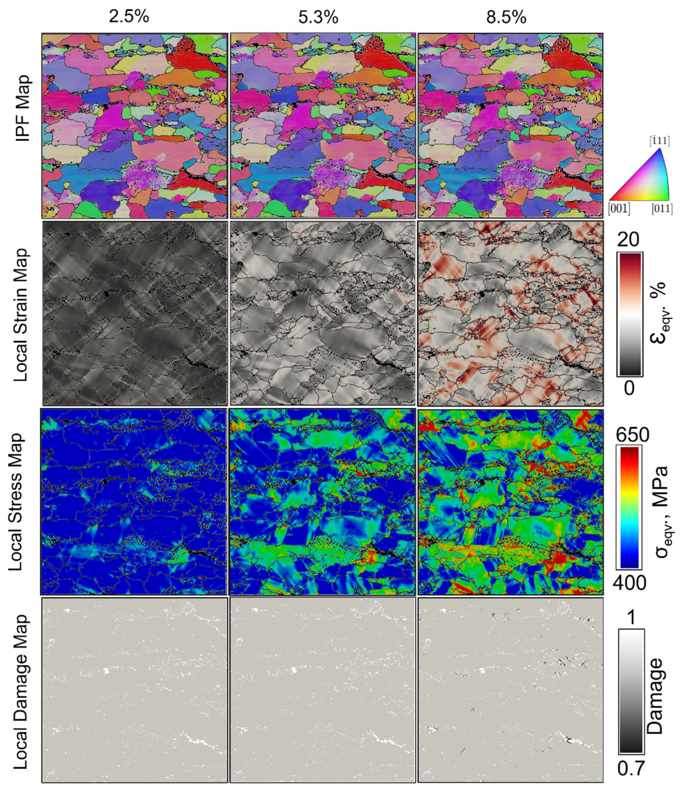
3.1. Global Results

The real microstructure-based RVEs of two differently spheroidization-annealed C45EC steel samples are modeled and subjected to monotonic quasi-static tensile load. The global material flow behavior is calculated by taking the local stress and strain average for each increment of load during numerical simulation (refer to Figure 3) as per Equations (5) and (6).
Generally, the plastic flow trends for both cases during simulation match well with the experimental results. For example, in Figure 3 (zone A), the experimental results show the actual material behavior. After the elastic region, both materials experience elastic to plastic transition where dislocation movement and pinning take place until a point is reached where the material starts to flow plastically. During simulation, this process of flow behavior is not observed similarly because the material model is meant to predict the plastic behavior, especially after zone A.
The trend for S-83 is obtained with less than 1% error in Figure 3, zone B involving the plastic flow region. For the S-97 sample, there is a maximum of 3.2% difference compared to experimental results. This accurate match suggests that the material model implemented is appropriately calibrated with experimental results globally. Therefore, it can be used to analyze and predict the local results of the RVE.
Figure 3, zone C has global results for the S-97 sample only, which undergoes comparatively more plastic flow during numerical simulations because of cementite particles’ fine distribution due to the extended intermittent spheroidization-annealing.
It is observed that the global material response for the S-83 sample with damage exhibits more strain hardening. A similar trend can be seen in the case of S-97 at the beginning, with comparatively reduced strength. Local ductile damage initiates in both the cases represented by Dam S-83 and Dam S-97, at a difference of ~2% global strain. Slight differences at the starting point of damage can be attributed to the unique microstructural architecture, which will be discussed in detail later.
After the first incidence of damage, strain hardening continues with experimental results from 3.7% to about 9% global strain for the S-83 material sample. For S-97, due to the homogenous distribution of hard and fine cementite particles, the damage is initiated later, i.e., 5.7% global strain, and continues until ~10% (Figure 3, zone B). Stiffness degradation is observed in the S-97 case after 9% of global strain in zone C, and damage incidents increase, represented in Figure 3, with Dam S-97 dashed green trend line.

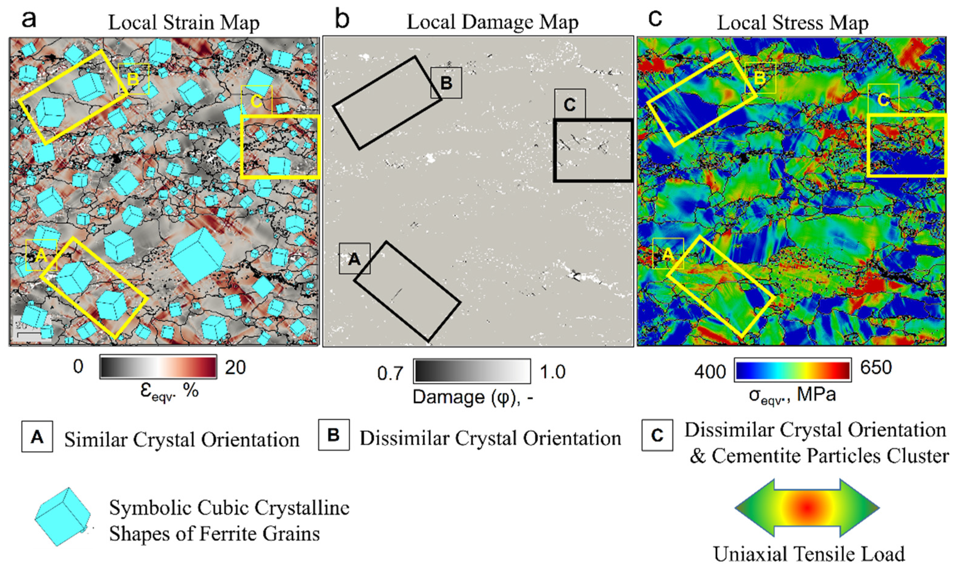
3.2. Local Results during Mechanical Deformation of S-83

Local maps for IPF, strain, stress and damage for the S-83 case are shown from top to bottom, respectively, in Figure 4 at increasing global strain, i.e., 2.5%, 5.3%, and 8.5%. Analyzing the local results at various critical points during the evolution of plastic deformation is very interesting to predict the initiation and high local concentration of stress and strain regions. Furthermore, the influence of cementite particle size, distribution, and clustering in the ductile ferrite matrix has a decisive effect on the overall mechanical behavior of the material. Therefore, this information is essential to understand and to improve the working of spheroidized C45EC steels.
Only ferrite phase is shown in all the local maps, while the cementite particles are represented by white dots (empty spaces) in local damage maps and by black dots in all the maps otherwise. This is because the substantial difference in the stresses and strains in both phases develops during deformation. For instance, the local stress points in cementite are observed as high as ~10GPa, while the average local stress shown for ferrite in the RVE for the S-83 sample is ~500 MPa. This difference distorts the scale and makes the simultaneous representation very challenging.
IPF map of the RVE can be seen to evolve due to applied strains. This evolution of the crystallographic orientation during deformation is interesting to note because the adjacent crystals shift their behavior according to the modified crystals’ orientation after every step of load increment. Not all ferrite grains change their orientation simultaneously, yet their individual locality contributes very highly to deciding their modified orientation.
The local strains are heterogeneously distributed in the RVE due to varying cementite particle sizes and distributions and the random orientations of the ferrite grains. It is worth mentioning here that the local strain distribution map of S-83 at 8.5% global strain shows substantial heterogeneity at various positions. This difference in heterogeneity is attributed to the considerable difference in the strength of both phases. The local strains start to develop first at the ferrite–cementite interface. Then, they continue to grow in the oblique directions compared with the direction of application of the quasi-static tensile load.
Although local stress distribution maps show lower stresses at the 2.5% global strain, a significant contrast is observed during evolution up to 8.5% global strain. A few ferrite–ferrite grain interfaces are observed where local stresses start to appear at 2.5% and continue to grow until 8.5% global strain. Even the individual grains at some points develop local equivalent stresses near to 650MPa. Damage incidents, on the other hand, are not observed until 5.3% global strain. The initial micro cracks captured in the local damage map at 8.3% global strain demonstrate that the multiple sites have their unique history and circumstances for the initiation of the local damage. Further explanation and investigation of micro-cracks indeed demand postmortem analysis of the RVEs to predict the rationale of the specific observation.
A profound analysis of the local stress, strain, and damage maps of S-83 at 8.5% global strain is presented in Figure 5. It gives an obvious idea about the dependence of the stress and strain localization influenced by crystallographic orientations of the ferrite grains. The resulting damage maps suggest that initial micro-cracks in the RVEs develop due to noticeable orientation differences in ferrite grains. The influence was studied by highlighting three zones on the RVE as shown in Figure 5, i.e.,
  • Zone A is defined to study the local stress, strain, and damage behavior of similarly orientated adjacent ferrite grain without any cementite particle inclusion.
  • To analyze the effect of the different orientations of one ferrite grain on its neighboring grain, zone B is marked on three local maps in Figure 5. This zone does not contain cementite particles; therefore, the significant behavior difference is influenced by the orientation of the ferrite grains.
  • The different orientations and the clustered cementite particles are highlighted in zone C, which is of utmost importance.
To understand the influence of the crystallographic orientation, all three zones need to be discussed one by one. Zone A, with similar crystallographic orientations of adjacent ferrite grains, shows similar local strain distribution across the grain boundary. This suggests the idea that a similar effect of local strain is shifted to the adjacent ferrite grain. A limitation of the material model must be considered here because grain boundary consideration is neglected in the present model. Zone A, having almost no cementite grain, provides the perfect area to study the complete phenomenon observation due to variation in crystallographic orientation. A local stress map can be seen in zone A with no substantial local stresses across the grain boundary. In the damage map, there can be seen a thin black-colored line showing local damage developed due to local strains. Ferrite, a ductile phase, undergoes extended deformation in the large grains, and similarly, oriented ferrite grains further aggravate this plastic flow.
Conversely, in Zone B, the orientation of the adjacent ferrite grains is dissimilar, giving rise to the local stress development across the grain boundary due to blockage of slip planes. On the other hand, local strains are not observed with a substantial difference, and consequently, no local damage incident is observed in zone B in the local damage map.
In Figure 5, Zone C is of utmost importance because the combination of different orientation and cementite clustering effects in the RVE with 83% spheroidization degree creates multiple damage sites in the close vicinity. It is also observed in Figure 5b zone C that the cementite clusters are even more prone to the generation of multiple damage initiation sites as compared with the cementite bands present in the right lower corner of the RVE. This synergetic effect of the microstructure combined with highly dissimilar crystallographic orientations and cementite particle clusters gives rise to the sharp oblique strain band formation. Once the initial cracks appear at the ferrite–cementite interface and they start to coalesce in proximity to each other, the sharp damage lines start to appear at various locations in the very close vicinity, making this region a highly local damage-affected zone.

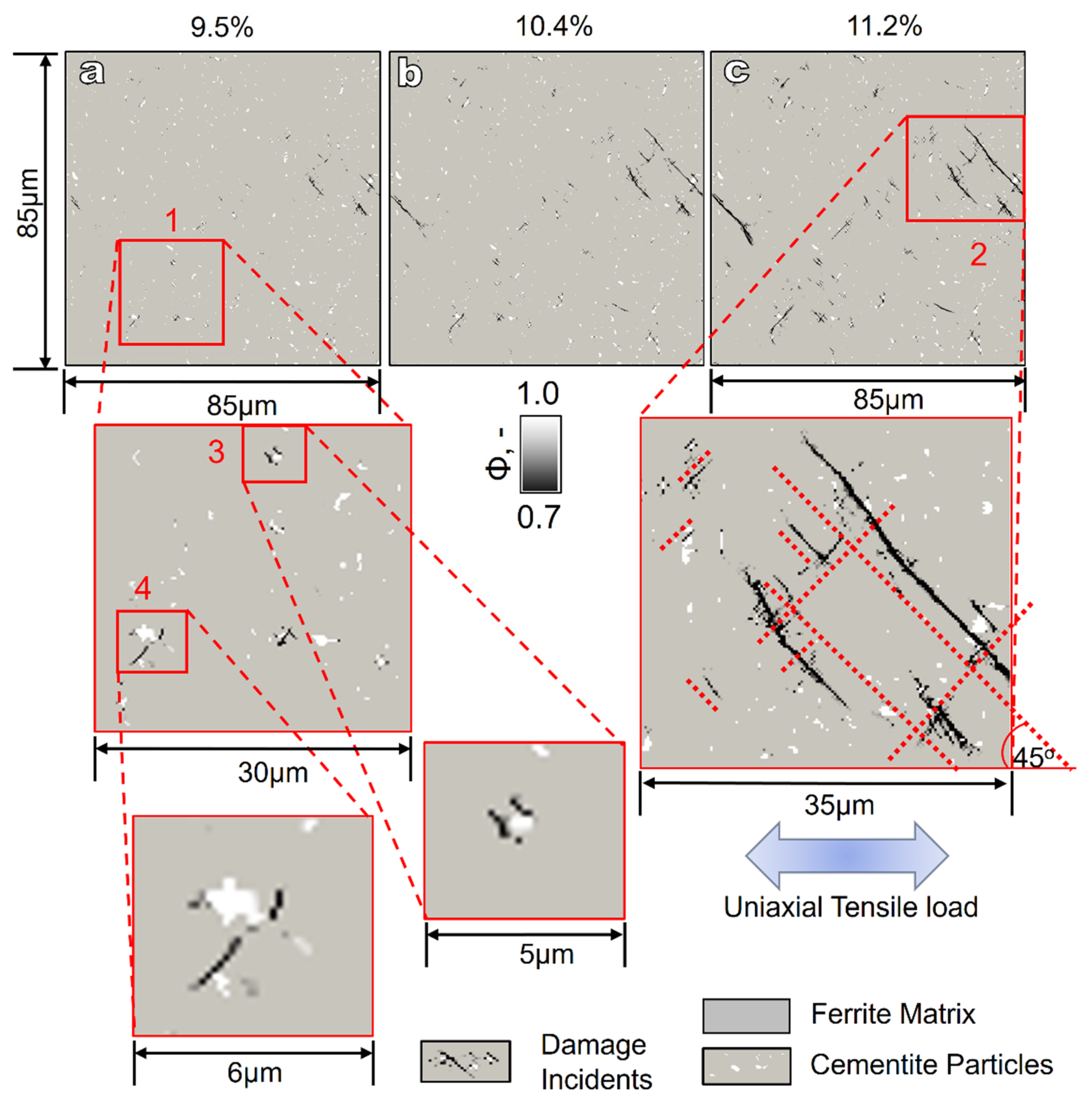
3.3. Local Results during Mechanical Deformation of S-97

The local results in the form of evolving IPF, local strain, stress, and damage maps for the case of S-97 are displayed in Figure 6. Generally, the evolution of the crystallographic orientation shows a slight difference, as in the case of S-83, due to random orientation.
The evolution of local strains in the microstructure of S-97 with finely distributed cementite particles is comparatively more homogenous, and the stresses are also distributed in the whole RVE at 8.5% global strain. Due to extended spheroidization, fine and well-distributed cementite particles in the whole RVE, the damage incidents are less frequent than the S-83 samples at the same global strain. The first damage incident in the S-97 sample is observed at about 5.5% global strain, i.e., 2% later than S-83.
The effect of evolving crystallographic orientation with reference to crystal shapes is displayed in Figure 7. It is observed that the crystal oriented towards the [001] direction initially tends to shift its orientation slightly towards the [011] direction during deformation. This evolution in orientation from 2.5% to 11.2% global strain is shown in the top inset images labeled as Figure 7a. Furthermore, the changing texture of the specific grain represented by 1 in Figure 7b in the unique neighborhood of all the differently oriented ferrite grains numbered from 2 to 6 in the same image suggests the strong influence of the orientation of surrounding grains during deformation.
The evolution in crystallographic orientation during deformation largely depends on the alignment feasibility of adjoining ferrite grains. A higher conformity in the form of similar orientation can lead to greater ease in plastic flow, and a lower similarity can lead to enhanced slip resistance in the form of slip locking. This can further give rise to the local stress concentration at a local material point. The triple points also play a role here by enhancing the vulnerability of crack initiation and the strain concentration in local regions.
A profound analysis of the damage growth in the spheroidized medium carbon steel sample after 97% spheroidization is explained with the help of various constructions in Figure 8. During mechanical deformation evolution, local damage maps are shown from 9.5% to 11.2% in Figure 8a–c, respectively, in the S-97 sample during micromechanical simulation. It is observed in Figure 8a that local cracks first appear as independent sites with a single element in damage at various places. They start to grow immediately as the deformation progresses from 9.5% to 11.2% global strain.
Zone 1 contains the sample area to study the initiation of the micro-cracks, with a magnified zone 3 and 4. The micromechanical model implemented in this study predicted the damage initiated at the ferrite–cementite interface, as shown in magnified zone 3 and zone 4. The process of the initiation of the micro-crack in areas with multiple cementite particles in close proximity causes severe strain localization, and the threshold of damage (i.e., εcrit = 0.5) is reached at multiple points in close vicinity.
Various local damage incidents join together, and the crack line appears to propagate in the oblique direction compared to the load direction. Moreover, it is observed that the damage incidents occur at the ferrite–cementite interface. For example, in zone 3, the damage incidents occur at the interface on both sides of the cementite particle, and afterwards, the damage propagates in a specific direction. Similarly, for zone 4, the hard cementite phase particles do not carry on the usual deformation in the ductile ferrite matrix, and they start to dissociate from the matrix.
Upon further investigating the propagation of the cracks, it is observed in Figure 8, zone 2, that the angle of the crack growth lines is approximately equal to the 45° compared with the uniaxial tensile load direction.

4. Discussion

The micromechanical material behavior of spheroidized medium carbon steels is evaluated using two cases of differently heat-treated samples with the same ferrite and cementite phase fraction. The varying microstructure-based real RVEs were subjected to the virtual monotonic quasi-static tensile load. After implementing the calibrated phenomenological material model with DAMASK, the global and local results are presented and analyzed to gain valuable insights. These insights are found to be in compliance with the previously published findings and conclusions for similar materials.
The numerical simulation for the S-83 case terminated during computation at ~9% of global strain. This is probably due to computational complexities involved due to multiple damage sites initiated within the clustered cementite particles at various places in the RVE (refer to Figure 1 and Figure 2).
Local damage initiation with a 2% delay in global strain for the S-97 sample suggests that the greater the homogeneous distribution of cementite particles, the lower the probability of starting damage incidents earlier. The S-83 sample is 83% spheroidized. It contains newly formed heterogeneously clustered cementite particles (~15 µm mean diameter). Within these clusters, the inter-particle spacing is small. During deformation, due to high local strains (refer to Figure 4 and Figure 6, local strain maps), these zones are more susceptible to interface dissociation. It is supported by the already reported similar findings for ferrite and martensite aggregates by Habibi et al. [44] and Pathak et al. [45]. In addition, it has been reported by Tasan et al. [20] that the hard-phase particles in the ductile ferrite matrix lead to the matrix–particle decohesion and local micro-crack initiation.
Contrary to this, the S-97 sample, having the same volumetric phase fraction and instead more homogeneously distributed fine (~11µm mean diameter) cementite particles, performs better in delaying the damage incident. Umar et al. [8] previously reported similar results for ferrite and cementite aggregate with a virtual microstructure subjected to tensile load under crystal plasticity-based numerical simulation.
This study has provided significant insights into the changing orientations of the ferrite grains during mechanical deformation (refer to Figure 5 and Figure 7). It is reported that the evolving texture during mechanical deformation potentially changes the material behavior in crystalline materials [27,46]. It is observed that damage initiation depends on the second particle grain size and their distribution. At the same time, the crack propagation and void coalescence in the ductile ferrite matrix are governed by the orientation distribution of the surrounding grains. Similar observations have already been reported for the ferrite and martensite combination in steels [44,47]. As shown in Figure 7, grain rotation can have detrimental effects on local formability. Panin et al. [48] showed that the extent of rotation energy accumulation determines the starting point for crack opening in the heterogeneously distributed aggregate. It has been observed that microstructural heterogeneity may influence the crystallographic texture evolution and plastic strains during deformation. Sidor reported a similar observation for aluminum alloys [49].
The propagation of the damage lines at a ±45° angle to the applied tensile load is observed in this ferrite–cementite aggregate of medium carbon C45EC steel. This suggests of the generation of strain bands or lüder bands in the ductile ferrite matrix. The information obtained from the present study can be implemented on the dual-phase aggregates, with a comparable difference in flow properties in the phases. The mechanism of the local stress concentration in two-phase systems—evaluated by crystal plasticity models—has already been reported by researchers to behave in a more or less similar manner. The experimental results presented with the help of micro digital image correlation (µDIC) by Weidner et al. [50] and Tasan et al. [51] also present a detailed overview of similar growth line propagation in a martensite–ferrite combination during tensile loading. This information and development in model calibration and implementation with micro-scale material input can be used for modern generations of advanced high strength steels. Qayyum et al. [52] concluded their work on the heterogeneous aggregated steels with ductile austenite and hard martensite phase as the damage in ductile matrix propagates at 45 degrees to the loading direction.
An important observation in Figure 8 is that the most susceptible damage site in the whole aggregate is the ferrite–cementite interface. Therefore, it is critical to strengthen the weakest point in the RVE for better local formability of the steels. Similarly, it was concluded by Weidner et al. [53] that in multi-phase steels, the interface of the ductile ferrite and the hard second-phase particles is the most susceptible to damage initiation. This work also shows that the early start of damage at ~6% global strain in S-97 restricts the load shift from ductile ferrite to the cementite particles, not fully utilizing the latter’s strength.
The following limitations are incorporated in the material model used for this study.
  • The grain boundary is considered ideally akin to the grains, and its intrinsic effect has been ignored.
  • The absence of a definition of ferrite–cementite interface-specific effects and properties.
In the near future, a consideration of the grain boundary and ferrite–cementite interface effects needs to be implemented in the material model. These additions can better predict stress and strain localization during crystallographic plane slip during adjacent grains interaction.

5. Conclusions

The microstructure dependence of differently spheroidized medium carbon steels is analyzed using calibrated phenomenological and micromechanics-based material model implemented in DAMASK. A methodology is presented which can be used to predict stress–strain localization and damage dynamics based on ferrite grain orientation and cementite particle size and distribution. After careful observation of results and correlating them with the similarly processed material behavior, as discussed in Section 4, the following conclusions are drawn for this study:
  • It is shown that the presented methodology and numerical simulation model can be used to study the global flow trends that match, with greater than 99% and 97% accuracy between the simulation and experimental results for the S-83 and S-97 sa mples, respectively, achieved for plastic flow region in zone B. Furthermore, the minimum error suggests that the local results presented in this study can be attributed to the actual material’s behavior.
  • The S-83 sample with cementite particle clusters has shown multiple damage incidents earlier than the S-97 sample, having fine and homogeneously distributed cementite particles. In addition, the first damage incident in the same material is delayed until 2% global strain only because of the well-designed heat-treatment process.
  • Contrary to the engineering (macroscopic) scale, the crystal plasticity-based simulation methodology can help us to understand the texture development and evolution during mechanical deformation. The crystallographic orientation of neighboring grains influences the grain orientation during thermo-mechanical deformation, changing the material behavior at the micro-level, and consequently at the component scale.
  • Within the presently taken 2D RVEs under monotonic tensile load, the damage initiation occurs at the ferrite–cementite interface and propagates at ±45° in relation to the direction of the applied load.

Author Contributions

Conceptualization, M.U. and F.Q.; methodology, M.U., F.Q. and M.U.F.; software, M.U.; validation, F.Q., M.U. and S.G.; formal analysis, M.U.; investigation, F.Q.; resources, S.G. and M.U.F.; writing—original draft preparation, M.U., F.Q., M.U.F., S.G. and U.P.; writing—review and editing, M.U., F.Q., M.U.F., S.G. and U.P.; visualization, M.U. and F.Q.; supervision, S.G., M.U.F. and U.P.; project administration, U.P.; funding acquisition, F.Q. and U.P. All authors have read and agreed to the published version of the manuscript.

Funding

This research was funded by Deutsche Forschungsgemeinschaft (DFG, German Research Foundation) within the framework of the collaborative research group “TRIP Matrix Composites” project number 54473466–SFB 799.

Institutional Review Board Statement

Not applicable.

Informed Consent Statement

Not applicable.

Data Availability Statement

The MTEX algorithms for EBSD data cleaning and numerical simulation are not available online but can be shared upon request.

Acknowledgments

The authors acknowledge the DAAD Faculty Development for Candidates (Balochistan), 2016 (57245990)-HRDI-UESTP’s/UET’s funding scheme in cooperation with the Higher Education Commission of Pakistan (HEC) for sponsoring the stay of Faisal Qayyum at IMF TU Freiberg. This work is conducted within the DFG funded collaborative research group TRIP Matrix Composites (SFB 799). The authors gratefully acknowledge the German Research Foundation (DFG) for the financial support of the SFB 799. Freunde und Förderer der TU Bergakademie Freiberg e.V. is acknowledged for providing financial assistance to Muhammad Umar. The authors also acknowledge the support of Martin Diehl and Franz Roters (MPIE, Düsseldorf) for their help regarding the functionality of DAMASK. The authors acknowledge the support provided by AGH Krakow, Poland to perform EBSD analysis using Merlin Gemini II (ZEISS), at international center of electron microscopy for material science. Finally, the competent authorities at Khwaja Fareed University of Engineering and Information Technology, (KFUEIT) Rahim Yar Khan, Pakistan, and TU BAF Germany are greatly acknowledged for providing research exchange opportunities to Muhammad Umar at the Institute of Metal forming TU BAF Germany under a memorandum of understanding (MoU).

Conflicts of Interest

The authors declare no conflict of interest.

References

  1. Rana, R.; Sing, S.B. Automotive Steels, Design, Metallurgy, Processing and Applications; Woodhead Publishing: Cambridgeshire, UK, 2017. [Google Scholar]
  2. Pan, H. Development and Application of Lightweight High-strength Metal Materials. MATEC Web Conf. 2018, 207, 03010. [Google Scholar] [CrossRef] [Green Version]
  3. Wilhelm, M. Materials used in automobile manufacture—current state and perspectives. J. Phys. 1993, 3, 7–31. [Google Scholar] [CrossRef] [Green Version]
  4. Wong, S.L.; Madivala, M.; Prahl, U.; Roters, F.; Raabe, D. A crystal plasticity model for twinning- and transformation-induced plasticity. Acta Mater. 2016, 118, 140–151. [Google Scholar] [CrossRef]
  5. Prasad, C.; Bhuyan, P.; Kaithwas, C.; Saha, R.; Mandal, S. Microstructure engineering by dispersing nano-spheroid cementite in ultrafine-grained ferrite and its implications on strength-ductility relationship in high carbon steel. Mater. Des. 2018, 139, 324–335. [Google Scholar] [CrossRef]
  6. Harisha, S.R.; Sharma, S.; Kini, U.A.; Shankar, M.C.G. Study on Spheroidization and Related Heat Treatments of Medium Carbon Alloy Steels. MATEC Web Conf. 2018, 144, 2008. [Google Scholar] [CrossRef]
  7. Joo, H.S.; Hwang, S.K.; Baek, H.M.; Im, Y.-T.; Son, I.-H.; Bae, C.M. The effect of a non-circular drawing sequence on spheroidization of medium carbon steel wires. J. Mater. Process. Technol. 2015, 216, 348–356. [Google Scholar] [CrossRef]
  8. Umar, M.; Qayyum, F.; Farooq, M.U.; Khan, L.A.; Guk, S.; Prahl, U. Investigating the Effect of Cementite Particle Size and Distribution on Local Stress and Strain Evolution in Spheroidized Medium Carbon Steels using Crystal Plasticity-Based Numerical Simulations. Steel Res. Int. 2021, 92, 1–13. [Google Scholar] [CrossRef]
  9. Song, W.; Choi, P.-P.; Inden, G.; Prahl, U.; Raabe, D.; Bleck, W. On the Spheroidized Carbide Dissolution and Elemental Partitioning in High Carbon Bearing Steel 100Cr6. Met. Mater. Trans. A 2013, 45, 595–606. [Google Scholar] [CrossRef]
  10. Lv, Z.; Wang, B.; Wang, Z.; Sun, S.; Fu, W. Effect of cyclic heat treatments on spheroidizing behavior of cementite in high carbon steel. Mater. Sci. Eng. A 2013, 574, 143–148. [Google Scholar] [CrossRef]
  11. Amos, P.K.; Bhattacharya, A.; Nestler, B.; Ankit, K. Mechanisms of pearlite spheroidization: Insights from 3D phase-field simulations. Acta Mater. 2018, 161, 400–411. [Google Scholar] [CrossRef]
  12. Guk, S.; Augenstein, E.; Zapara, M.; Kawalla, R.; Prahl, U. Effect of Spheroidization Annealing on Pearlite Banding. Mater. Sci. Forum 2019, 949, 40–47. [Google Scholar] [CrossRef] [Green Version]
  13. Tasan, C.; Diehl, M.; Yan, D.; Bechtold, M.; Roters, F.; Schemmann, L.; Zheng, C.; Peranio, N.; Ponge, D.; Koyama, M.; et al. An Overview of Dual-Phase Steels: Advances in Microstructure-Oriented Processing and Micromechanically Guided Design. Annu. Rev. Mater. Res. 2015, 45, 391–431. [Google Scholar] [CrossRef]
  14. Mohammed, B.; Park, T.; Pourboghrat, F.; Hu, J.; Esmaeilpour, R.; Abu-Farha, F. Multiscale crystal plasticity modeling of multiphase advanced high strength steel. Int. J. Solids Struct. 2018, 151, 57–75. [Google Scholar] [CrossRef]
  15. Ghadbeigi, H.; Pinna, C.; Celotto, S. Failure mechanisms in DP600 steel: Initiation, evolution and fracture. Mater. Sci. Eng. A 2013, 588, 420–431. [Google Scholar] [CrossRef]
  16. Li, Z.-X.; Li, C.-S.; Zhang, J.; Qiao, B.; Li, Z.-Z. Effects of Annealing on Carbides Size and Distribution and Cold Formability of 1.0C-1.5Cr Bearing Steel. Metall. Mater. Trans. A Phys. 2015, 46, 3220–3231. [Google Scholar] [CrossRef]
  17. Storojeva, L.; Ponge, D.; Kaspar, R.; Raabe, D. Development of microstructure and texture of medium carbon steel during heavy warm deformation. Acta Mater. 2004, 52, 2209–2220. [Google Scholar] [CrossRef] [Green Version]
  18. Saha, A.; Mondal, D.K.; Maity, J. Effect of cyclic heat treatment on microstructure and mechanical properties of 0.6wt% carbon steel. Mater. Sci. Eng. A 2010, 527, 4001–4007. [Google Scholar] [CrossRef]
  19. Matusiewicz, P.; Augustyn-Nadzieja, J.; Czarski, A.; Skowronek, T. Kinetics of pearlite spheroidization. Arch. Metall. Mater. 2017, 62, 231–234. [Google Scholar] [CrossRef] [Green Version]
  20. Tasan, C.; Hoefnagels, J.; Diehl, M.; Yan, D.; Roters, F.; Raabe, D. Strain localization and damage in dual phase steels investigated by coupled in-situ deformation experiments and crystal plasticity simulations. Int. J. Plast. 2014, 63, 198–210. [Google Scholar] [CrossRef] [Green Version]
  21. Maruschak, P.O.; Panin, S.V.; Stachowicz, F.; Danyliuk, I.M.; Vlasov, I.; Bishchak, R.T. Structural levels of fatigue failure and damage estimation in 17Mn1Si steel on the basis of a multilevel approach of physical mesomechanics. Acta Mech. 2015, 227, 151–157. [Google Scholar] [CrossRef]
  22. Qayyum, F.; Guk, S.; Kawalla, R.; Prahl, U. On Attempting to Create a Virtual Laboratory for Application-Oriented Microstructural Optimization of Multi-Phase Materials. Appl. Sci. 2021, 11, 1506. [Google Scholar] [CrossRef]
  23. Diehl, M.; An, D.; Shanthraj, P.; Zaefferer, S.; Roters, F.; Raabe, D. Crystal plasticity study on stress and strain partitioning in a measured 3D dual phase steel microstructure. Phys. Mesomech. 2017, 20, 311–323. [Google Scholar] [CrossRef]
  24. Umar, M.; Qayyum, F.; Farooq, M.U.; Khan, L.A.; Guk, S.; Prahl, U. Analyzing the cementite particle size and distribution in heterogeneous microstructure of C45EC steel using crystal plasticity based DAMASK code. In Proceedings of the 2021 International Bhurban Conference on Applied Sciences and Technologies (IBCAST), Islamabad, Pakistan, 12–16 January 2021; pp. 15–20. [Google Scholar] [CrossRef]
  25. Qayyum, F.; Umar, M.; Guk, S.; Schmidtchen, M.; Kawalla, R.; Prahl, U. Effect of the 3rd dimension within the representative volume element (Rve) on damage initiation and propagation during full-phase numerical simulations of single and multi-phase steels. Materials 2020, 14, 42. [Google Scholar] [CrossRef]
  26. Qayyum, F.; Chaudhry, A.A.; Guk, S.; Schmidtchen, M.; Kawalla, R.; Prahl, U. Effect of 3d representative volume element (Rve) thickness on stress and strain partitioning in crystal plasticity simulations of multi-phase materials. Crystals 2020, 10, 944. [Google Scholar] [CrossRef]
  27. Diehl, M.; Groeber, M.; Haase, C.; Molodov, D.A.; Roters, F.; Raabe, D. Identifying Structure–Property Relationships Through DREAM.3D Representative Volume Elements and DAMASK Crystal Plasticity Simulations: An Integrated Computational Materials Engineering Approach. JOM 2017, 69, 848–855. [Google Scholar] [CrossRef] [Green Version]
  28. Zhang, C.; Li, H.; Eisenlohr, P.; Liu, W.; Boehlert, C.; Crimp, M.; Bieler, T. Effect of realistic 3D microstructure in crystal plasticity finite element analysis of polycrystalline Ti-5Al-2.5Sn. Int. J. Plast. 2015, 69, 21–35. [Google Scholar] [CrossRef] [Green Version]
  29. Prahl, U.; Qayyum, F.; Guk, S.; Kawalla, R. Effect of Sulphur Content on Formability of a Low Alloyed Steel. In Proceedings of the NEMU 2019, Vitoria-Gasteiz, Spain, 10 May 2019. [Google Scholar]
  30. Roters, F.; Diehl, M.; Shanthraj, P.; Eisenlohr, P.; Reuber, C.; Wong, S.; Maiti, T.; Ebrahimi, A.; Hochrainer, T.; Fabritius, H.-O.; et al. DAMASK—The Düsseldorf Advanced Material Simulation Kit for modeling multi-physics crystal plasticity, thermal, and damage phenomena from the single crystal up to the component scale. Comput. Mater. Sci. 2019, 158, 420–478. [Google Scholar] [CrossRef]
  31. Guk, S.; Kawalla, R.; Prahl, U. Mathematical Description of the Microstructural Modifications and Changes in the Mechanical Properties during Spheroidization of Medium-Carbon Steel. Steel Res. Int. 2019, 90, 1–8. [Google Scholar] [CrossRef]
  32. Hielscher, R.; Silbermann, C.B.; Schmidl, E.; Ihlemann, J. Denoising of crystal orientation maps. J. Appl. Crystallogr. 2019, 52, 984–996. [Google Scholar] [CrossRef] [Green Version]
  33. Bachmann, F.; Hielscher, R.; Schaeben, H. Grain detection from 2d and 3d EBSD data—Specification of the MTEX algorithm. Ultramicroscopy 2011, 111, 1720–1733. [Google Scholar] [CrossRef] [PubMed]
  34. Niessen, F.; Nyyssönen, T.; Gazder, A.A.; Hielscher, R. Parent grain reconstruction from partially or fully transformed microstructures in MTEX. J. Chem. Inf. Model. 2013, 53, 1689–1699. [Google Scholar]
  35. Khan, U.A.; Hussain, A.; Shah, M.; Shuaib, M.; Qayyum, F. Investigation of mechanical properties based on grain growth and microstructure evolution of alumina ceramics during two step sintering process. In IOP Conference Series: Materials Science and Engineering, Porceedings of 14th International Symposium on Advanced Materials, Islamabad, Pakistan, 12–16 October 2015; IOP Publishing: Bristol, UK, 2016; Volunme 146, pp. 8–15. [Google Scholar] [CrossRef] [Green Version]
  36. Najabat Ali, M.; Ansari, U.; Sami, J.; Qayyum, F.; Mir, M. To Develop a Biocompatible and Biodegradable Polymer-Metal Composite with Good; Mechanical and Drug Release Properties. J. Mater. Sci. Eng. 2016, 5, 1–4. [Google Scholar] [CrossRef] [Green Version]
  37. Tsumura, K. Hierarchically Aggregated Optimization Algorithm for Heterogeneously Dispersed Utility Functions. IFAC PapersOnLine 2017, 50, 14442–14446. [Google Scholar] [CrossRef]
  38. Chen, J.; Sun, Y. A new multiplexed optimization with enhanced performance for complex air conditioning systems. Energy Build. 2017, 156, 85–95. [Google Scholar] [CrossRef]
  39. Różyło, P.; Wrzesińska, K. Numerical analysis of the behavior of compressed thin-walled elements with holes. Adv. Sci. Technol. Res. J. 2016, 10, 199–206. [Google Scholar] [CrossRef] [Green Version]
  40. Kačeniauskas, A.; Pacevič, R.; Bugajev, A.; Katkevičius, T. Efficient visualization by using ParaView software on BalticGrid. Inf. Technol. Control. 2010, 39, 108–115. [Google Scholar] [CrossRef]
  41. Qayyum, F.; Guk, S.; Schmidtchen, M.; Kawalla, R.; Prahl, U. Modeling the local deformation and transformation behavior of cast X8CrMnNi16-6-6 TRIP steel and 10% Mg-PSZ composite using a continuum mechanics-based crystal plasticity model. Crystals 2020, 10, 221. [Google Scholar] [CrossRef] [Green Version]
  42. Qayyum, F.; Guk, S.; Prüger, S.; Schmidtchen, M.; Saenko, I.; Kiefer, B.; Kawalla, R.; Prahl, U. Investigating the local deformation and transformation behavior of sintered X3CrMnNi16-7-6 TRIP steel using a calibrated crystal plasticity-based numerical simulation model. Int. J. Mater. Res. 2020, 111, 392–404. [Google Scholar] [CrossRef]
  43. Roters, F.; Eisenlohr, P.; Kords, C.; Tjahjanto, D.D.; Diehl, M.; Raabe, D. DAMASK: The Düsseldorf Advanced MAterial Simulation Kit for studying crystal plasticity using an FE based or a spectral numerical solver. Procedia IUTAM 2012, 3, 3–10. [Google Scholar] [CrossRef] [Green Version]
  44. Habibi, N.; Vajragupta, N. Deformation and Damage Assessments of Two DP1000 Steels Using a Micromechanical Modelling Method. Crystals 2021, 11, 805. [Google Scholar] [CrossRef]
  45. Pathak, N.; Butcher, C.; Worswick, M.J.; Bellhouse, E.; Gao, J. Damage evolution in complex-phase and dual-phase steels during edge stretching. Materials 2017, 10, 346. [Google Scholar] [CrossRef] [PubMed] [Green Version]
  46. Raabe, D. Contribution of {123} 〈111〉 slip systems to deformation of b.c.c. metals. Phys. Status Solidi. 1995, 149, 575–581. [Google Scholar] [CrossRef]
  47. Marteau, J.; Haddadi, H.; Bouvier, S. Investigation of Strain Heterogeneities Between Grains in Ferritic and Ferritic-Martensitic Steels. Exp. Mech. 2012, 53, 427–439. [Google Scholar] [CrossRef]
  48. Panin, S.; Moiseenko, D.; Maksimov, P.; Vlasov, I.; Byakov, A.; Maruschak, P.; Berto, F.; Schmauder, S.; Vinogradov, A. Influence of energy dissipation at the interphase boundaries on impact fracture behaviour of a plain carbon steel. Theor. Appl. Fract. Mech. 2018, 97, 478–499. [Google Scholar] [CrossRef]
  49. Sidor, J.J. Crystal plasticity and continuum mechanics-based modelling of deformation and recrystallization textures in aluminum alloys. IOP Conf. Ser. Mater. Sci. Eng. 2018, 375, 12028. [Google Scholar] [CrossRef]
  50. Weidner, A.; Biermann, H. Review on Strain Localization Phenomena Studied by High-Resolution Digital Image Correlation. Adv. Eng. Mater. 2021, 23, 2001409. [Google Scholar] [CrossRef]
  51. Tasan, C.; Diehl, M.; Yan, D.; Zambaldi, C.; Shanthraj, P.; Roters, F.; Raabe, D. Integrated experimental–simulation analysis of stress and strain partitioning in multiphase alloys. Acta Mater. 2014, 81, 386–400. [Google Scholar] [CrossRef]
  52. Qayyum, F.; Guk, S.; Prahl, U. Studying the Damage Evolution and the Micro-Mechanical Response of X8CrMnNi16-6-6 TRIP Steel Matrix and 10% Zirconia Particle Composite Using a Calibrated Physics and Crystal-Plasticity-Based Numerical Simulation Model. Crystals 2021, 11, 759. [Google Scholar] [CrossRef]
  53. Weidner, A.; Berek, H.; Segel, C.; Aneziris, C.G.; Biermann, H. In Situ Tensile Deformation of TRIP Steel/Mg-PSZ Composites. Mater. Sci. Forum 2013, 738, 77–81. [Google Scholar] [CrossRef]
Figure 1. Post-cleaning EBSD-based RVEs with different grain morphologies depending upon the degree of spheroidization and thermo-mechanical processing route. The cementite particles are shown with the help of red color distributed heterogeneously in S-83 (a). After intermittent spheroidization treatment in S-97, the cementite particles are homogenously observable as red color in (b).
Jcs 05 00222 g001
Figure 2. Flow diagram of the activities performed when solving the crystal plasticity-based phenomenological material model implemented in DAMASK. The input, output, process, and terminal points are shown as a parallelogram, rhombus, rectangle, and ellipse, respectively.
Jcs 05 00222 g002
Figure 3. Comparison of experimental and simulation flow curves and damage trend lines of S-83 and S-97 samples with different spheroidization states based on actual RVEs. The three zones in the graph, A, B, and C, represent elastic, plastic, and extended plastic regions, respectively.
Jcs 05 00222 g003
Figure 4. Local maps (from top to bottom) for IPF, strain, stress, and damage for the S-83 sample with respective legends/scales. Local maps at global strains, i.e., 2.5%, 5.3%, and 8.5%, are shown from left to right for local behavior insight during the evolution of mechanical deformation.
Jcs 05 00222 g004
Figure 5. Comparison of local stress, strain, and damage maps of the S-83 sample at 8.3% global strain with zone A, B, and C pointing out crystallographic orientation that is similar, dissimilar, and dissimilar to the cementite particle cluster, respectively. (a) Local strain map with overlaid ferrite grain actual crystal orientation recorded during EBSD analysis, (b) local damage map of the S-83 RVE, and (c) local stress map.
Jcs 05 00222 g005
Figure 6. Local maps (from top to bottom) for IPF, strain, stress, and damage for the S-97 sample with respective legends/scales. Local maps at global strains, i.e., 2.5%, 5.3%, and 8.5%, are shown from left to right for local behavior insight during the evolution of mechanical deformation.
Jcs 05 00222 g006
Figure 7. Crystallographic orientation evolution of ferrite grains for the S-97 sample shown (a) at multiple global strain values, i.e., 2.5%, 5.3%, 8.5%, and 11.2%. (b) Close look at the ferrite grain labeled with 1 and orientation distribution of neighboring grains labeled with numbers 2 to 6. Corresponding legends for the IPF map and crystal shapes are given for clear understanding and reference.
Jcs 05 00222 g007
Figure 8. Local damage maps for the S-97 sample at different global strains, i.e., (a) 9.5%, (b) 10.4%, and (c) 11.2%. Zone 1 is selected to show the damage initiation sites at the ferrite–cementite interface magnified in zone 3 and 4. Zone 2 is marked and magnified to show the damage propagation lines at 45° with the direction of the application of the tensile load.
Jcs 05 00222 g008
Table 1. Chemical composition of the investigated C45EC steel in weight percentage.
ElementCSiMnPSCrMoNiAlCu
Percentage0.440.100.750.0070.0170.040.0110.040.030.03
Table 2. The nomenclature and ferrite phase information for two spheroidization cases of C45EC steels.
Sample CaseSpheroidization Degree, %Mean Ferrite Equivalent Diameter, µmMax Ferrite Equivalent Diameter, µmGlobal Strain at Damage Initiation, %
S-838315.0369.863.78
S-979711.9638.435.69
Table 3. Elastic, plastic, and damage parameters for the ductile ferrite matrix and elastic phase parameters for the hard cementite phase. Data adapted from previously published work [8,25] with the kind permission of Wiley and MDPI, respectively.
Elastic and Plastic Phase Parameters [8]
Parameter DescriptionValues for FerriteUnit
C11, C12, C44 233.3, 235.5, 128.0GPa
C11, C12, C44 (Cementite)375.0, 161.0, 130.0GPa
γ ˙ 05.6 × 10⁻⁴ms−1
S0[111], S s [111]95, 222MPa
S0[112], S s [112]96, 412MPa
ho, hαβ1, 1GPa
n, w3, 2.0-
Nslip12, 12-
Ntwin0-
Ductile Damage Parameters [25]
Interface Energy (g0)1.0Jm−2
Damage mobility coefficient (M)0.001s−1
Critical plastic strain (εcrit)0.5-
Damage rate sensitivity coefficient (P)10-
Damage diffusion (D)1.0-
Damage typeLocal-
Publisher’s Note: MDPI stays neutral with regard to jurisdictional claims in published maps and institutional affiliations.

