
New Frontiers of Composites Applications in Heritage Buildings: Repair of Exposed Masonry of St. Nicola Church in Pisa


Abstract
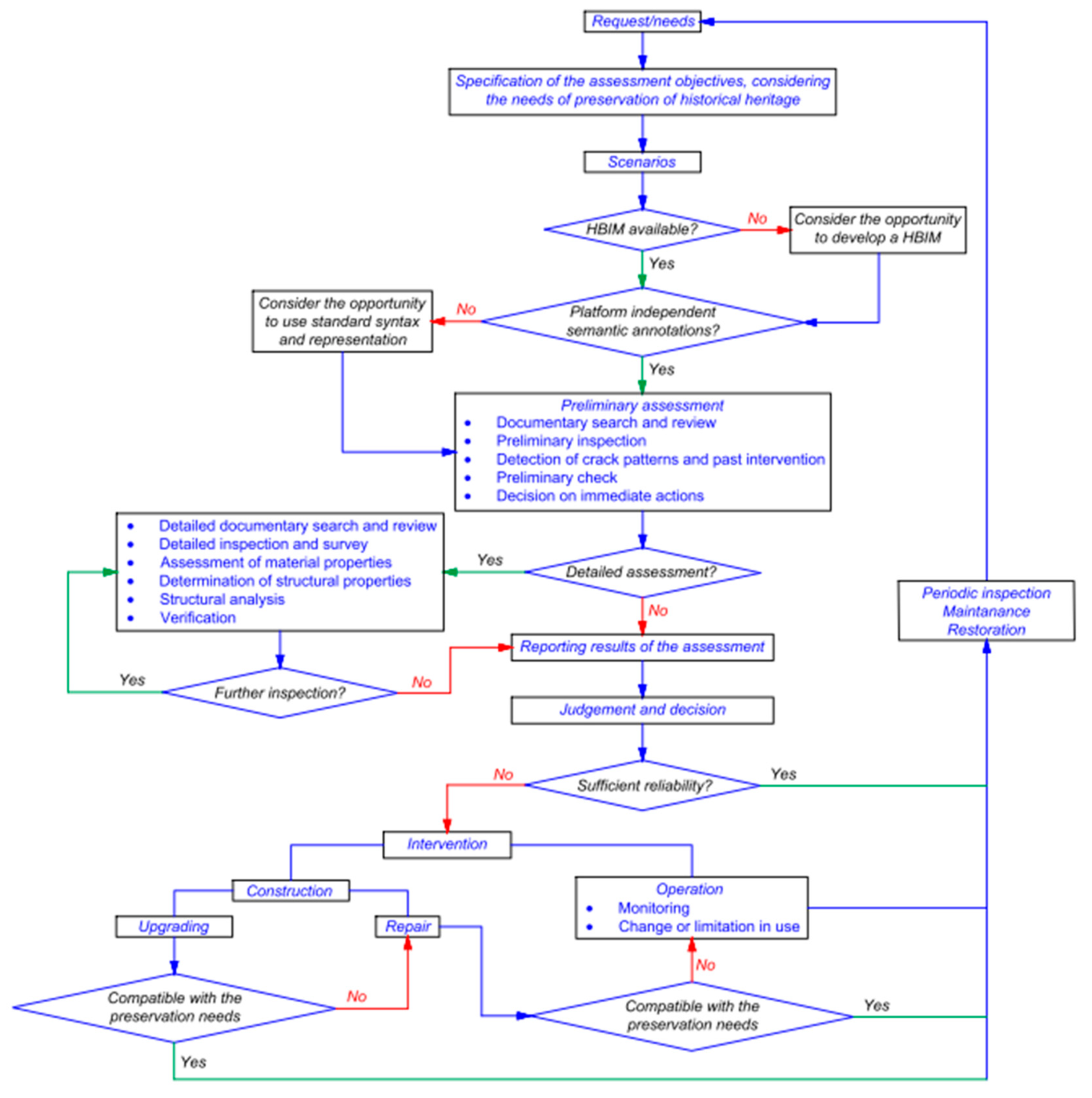
:1. Introduction
- construction, or
- operation.
- preparation of the composite strip of the given length,
- removal of the mortar of the bed joints near the external surface,
- insertion of the strip, (...),
- injection of the resin to fill the joint and glue the strip to the masonry.
2. The Proposed Strengthening and Repair Technique of Exposed Masonry
- identification of the position of the brick masonry course of interest for the intervention,
- preparation of a fiber strip of adequate length: the roll is formed starting from a fabric of the appropriate fiber: namely, aramid, carbon, glass, etc.; the width of the fabric should be a suitable multiple of the final width of the strip, in such a way that, folding the fabric one or more times or by superimposing more than one fabric, the desired thickness, and cross section area, is obtained,
- rolling up of the fiber strip,
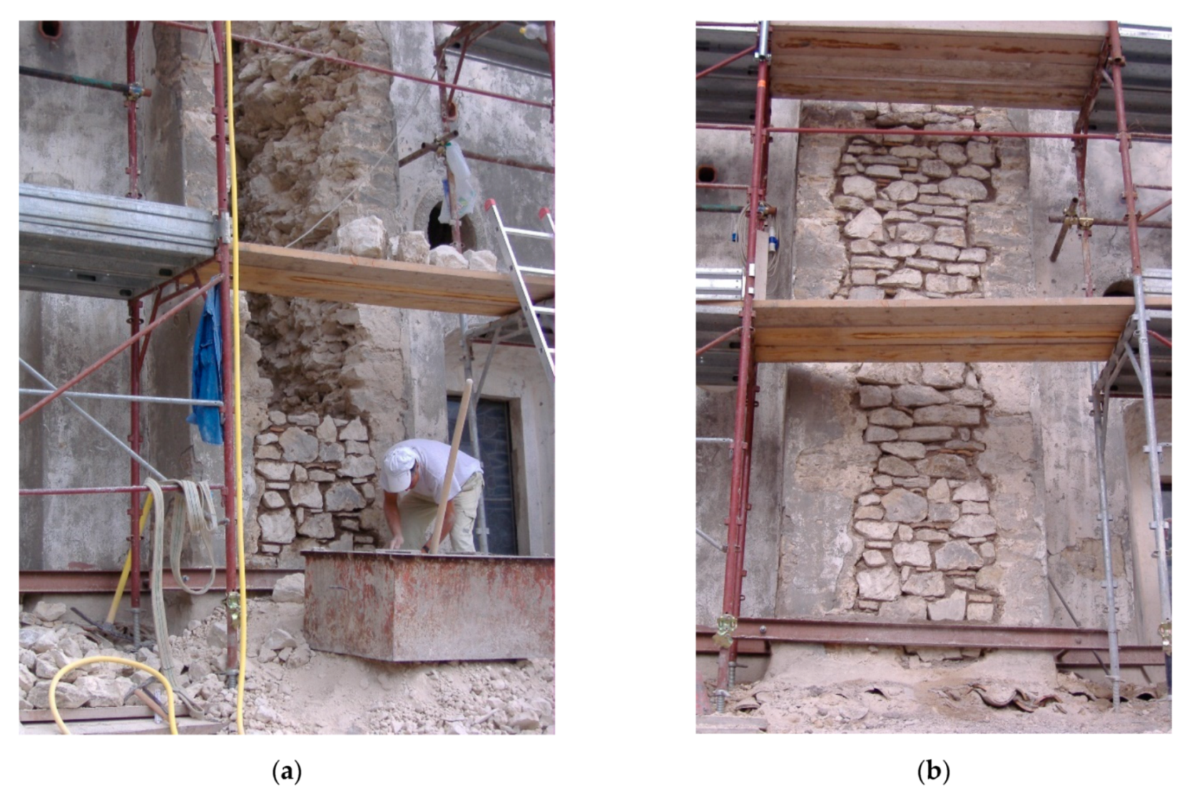
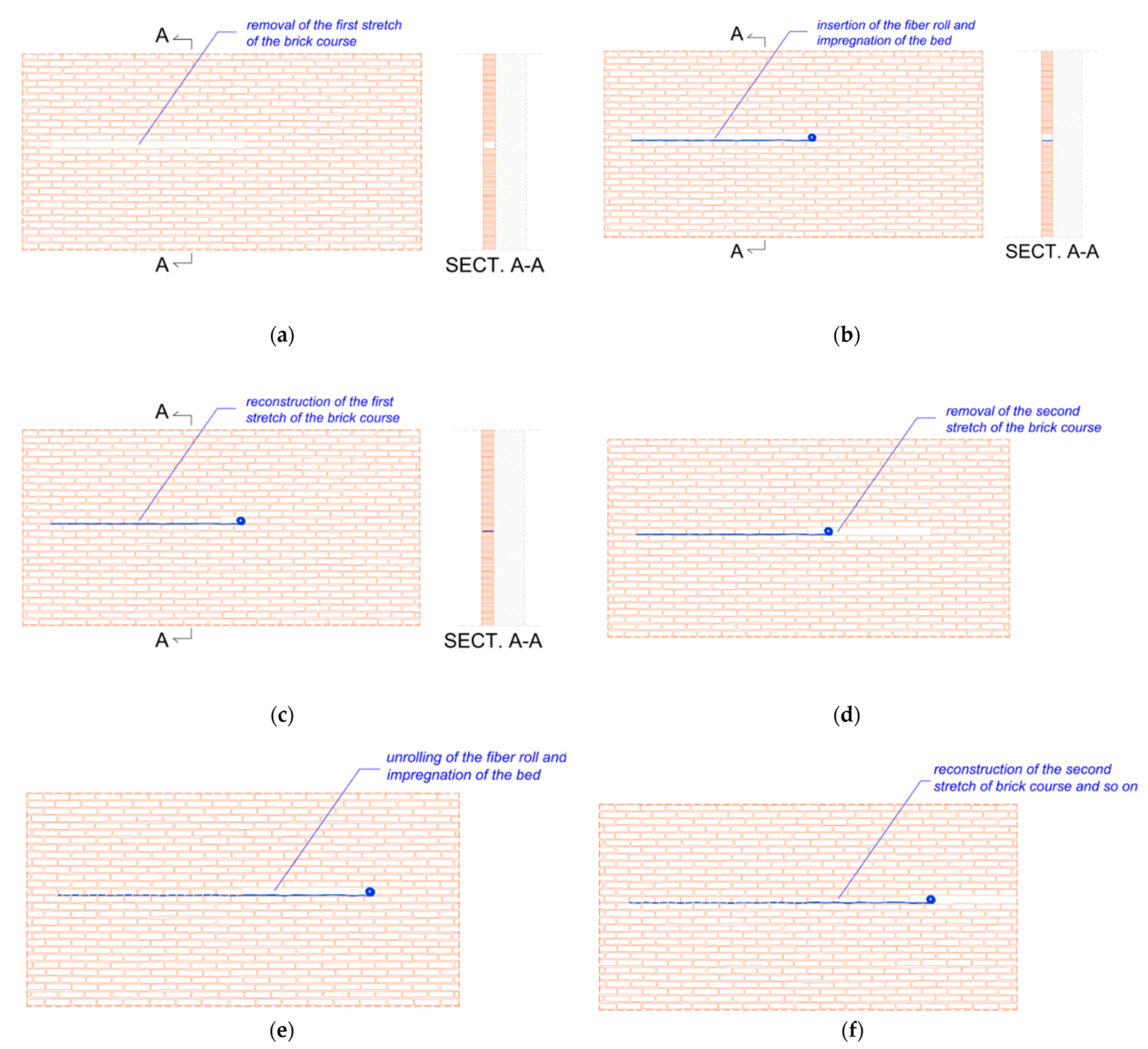
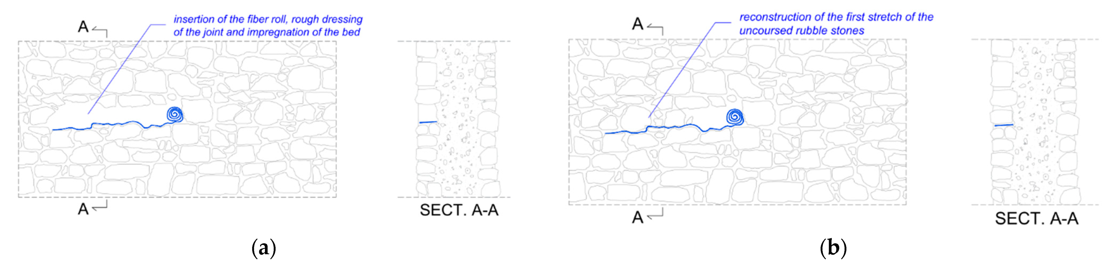
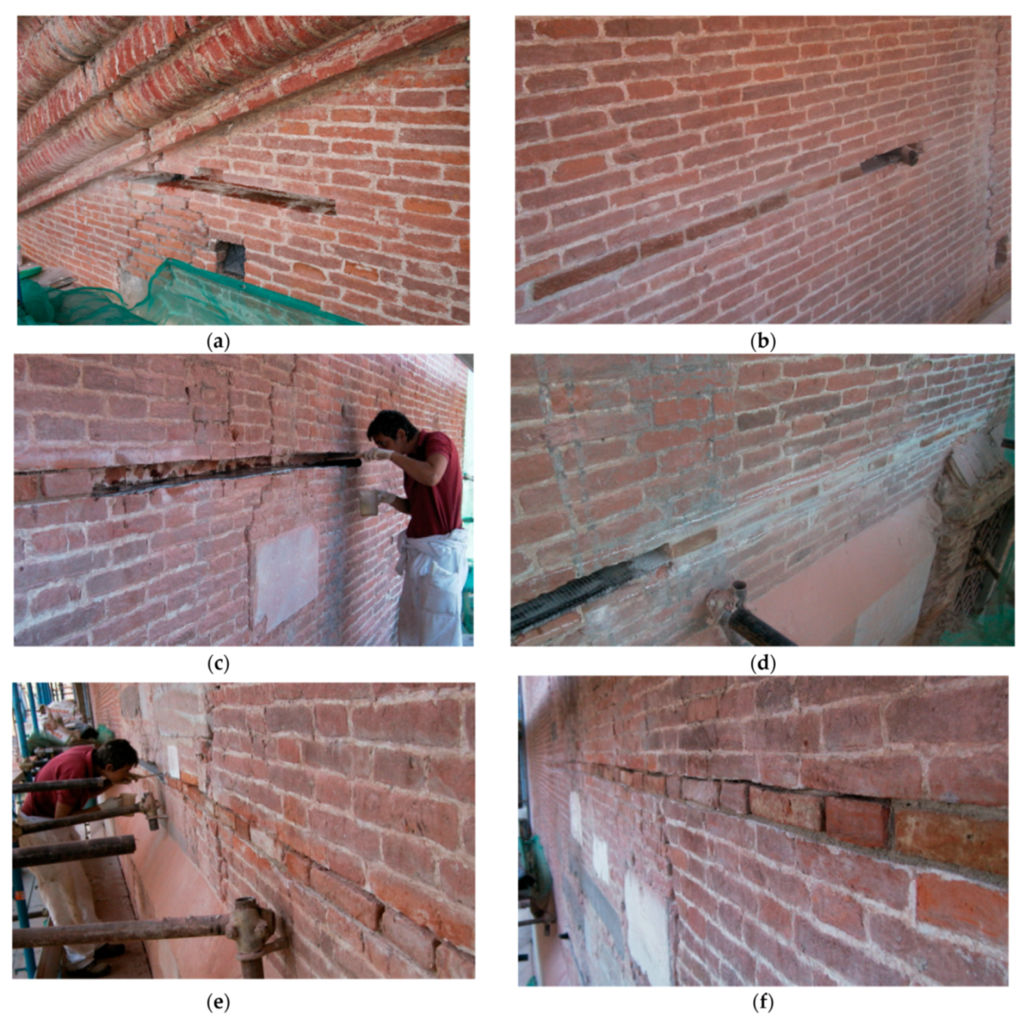
- starting of the indent: careful removal of the first stretch of the brick course (Figure 9a), and cleaning of the so obtained recess,
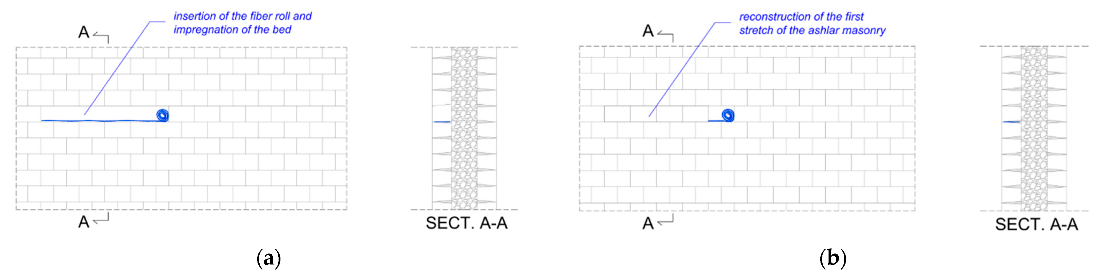
- application, using a spatula or a paintbrush, of low viscosity polymeric resin, for example, epoxy resin, insertion and partial unrolling of the fiber roll and its impregnation with the resin (Figure 9b),
- waiting until the resin is suitably cured, typically 24 h;
- reconstruction of the stretch of the brick course: reinsertion of the bricks and renovation of mortar joints (Figure 9c), using a mortar having a composition similar to the historical one, for example, a lime mortar,
- removal of the second stretch of the bridge course (Figure 9d),
- unrolling and impregnation of the fiber roll, as in step 5 (Figure 9e),
- reconstruction of the stretch and renovation of mortar joints, as in step 6, and so on until the total extension of the course is completed (Figure 9f).
- extension to other types of exposed masonry,
- feasibility in real cases,
- appearance of the exposed masonry at the end of the intervention,
- effectiveness over time.
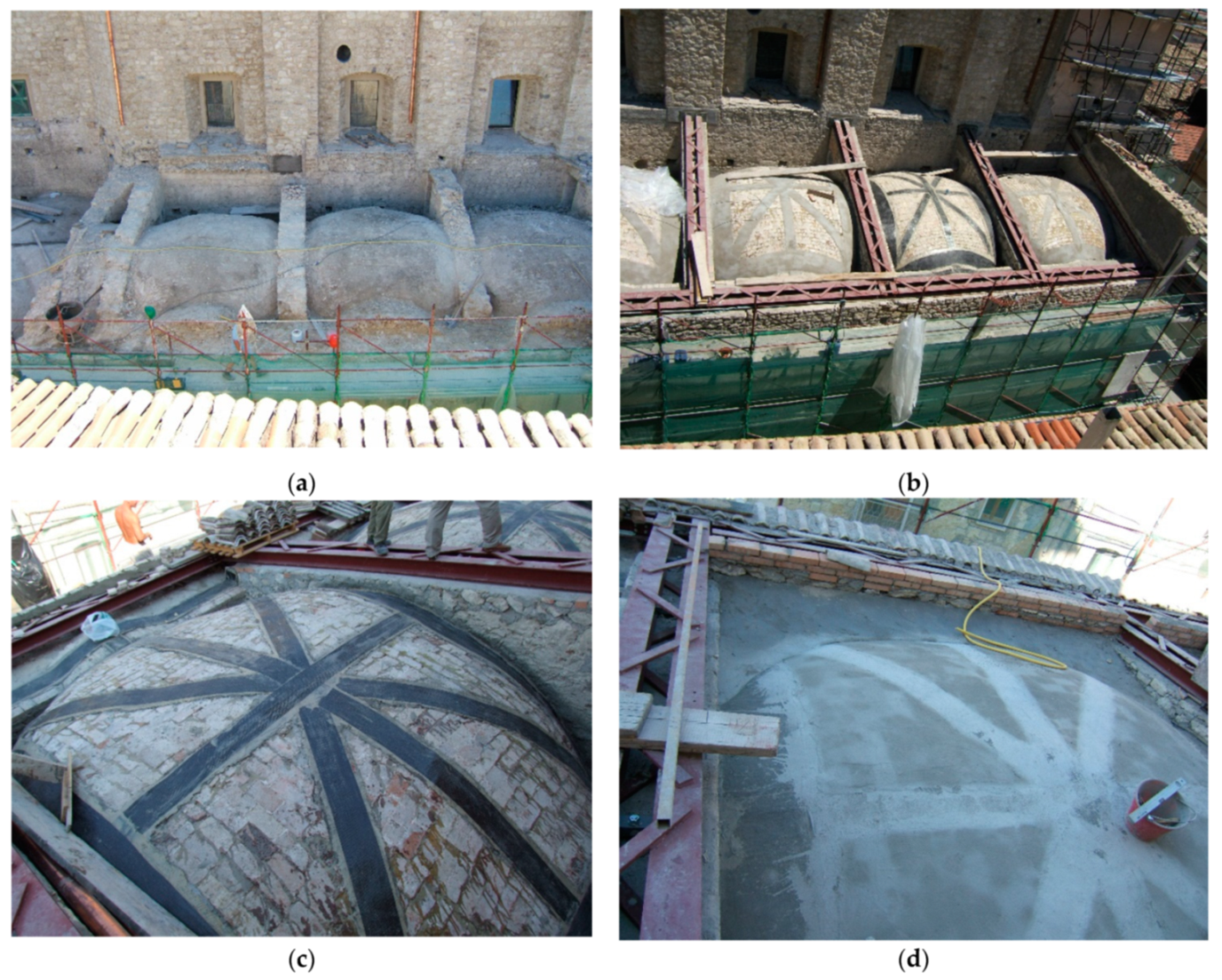
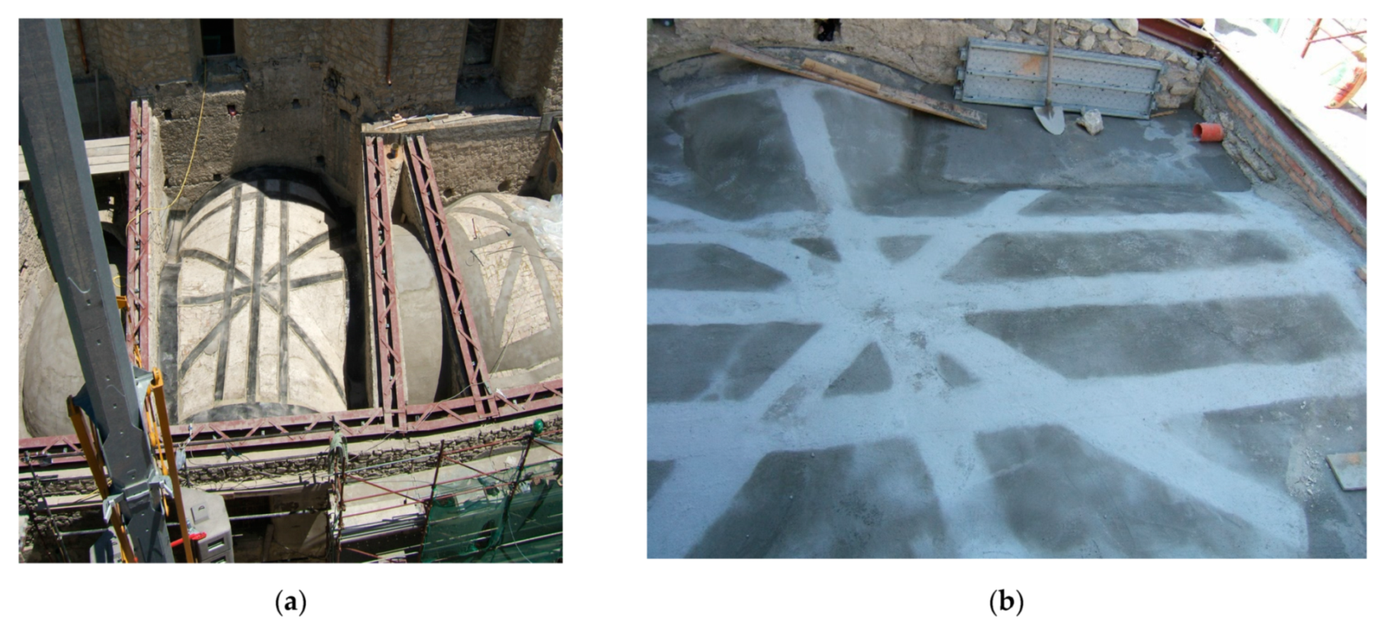
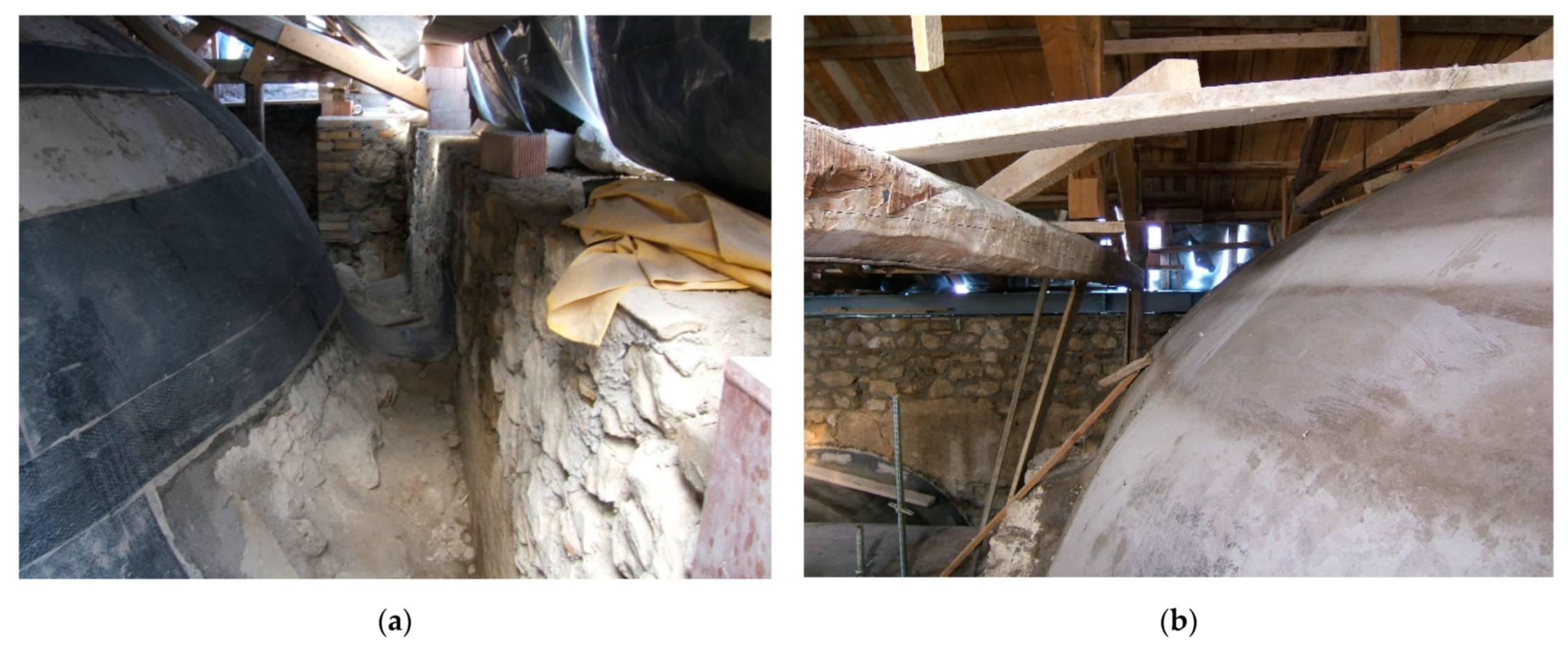
3. The Case Study: The Restoration of St. Nicola Church in Pisa
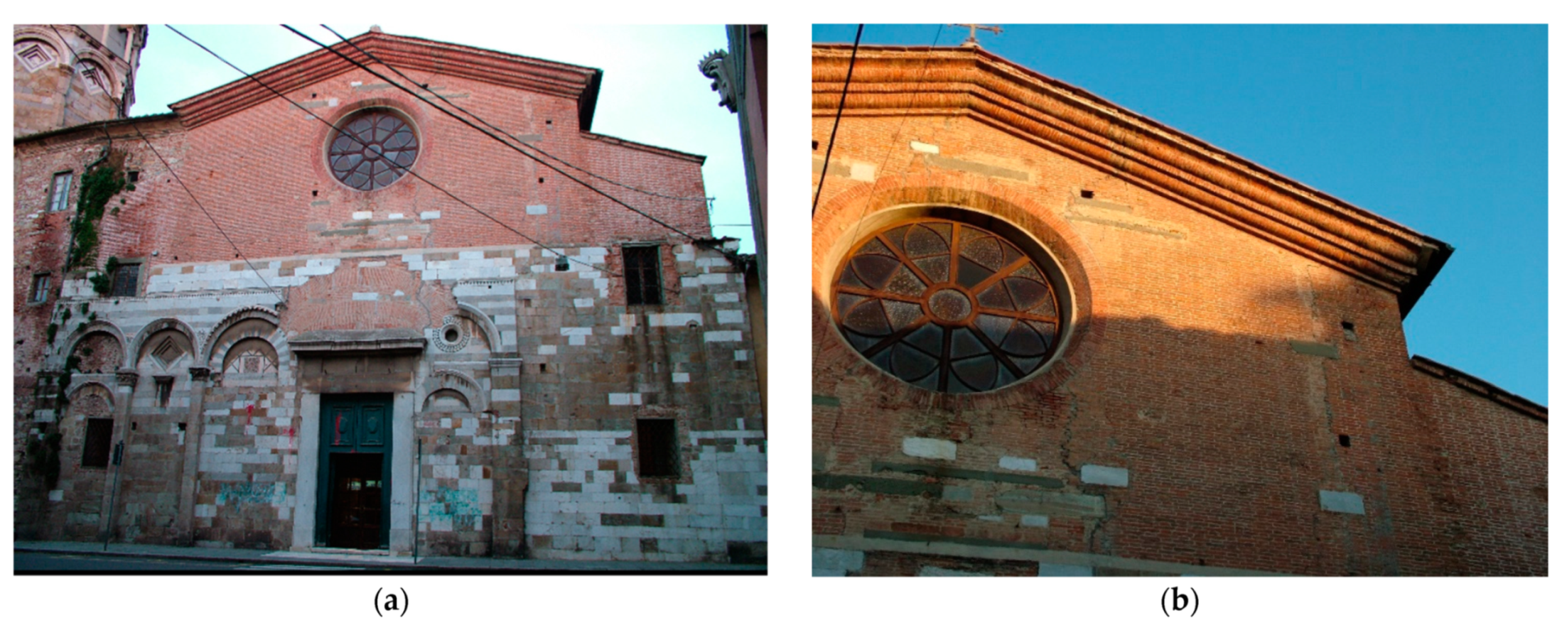
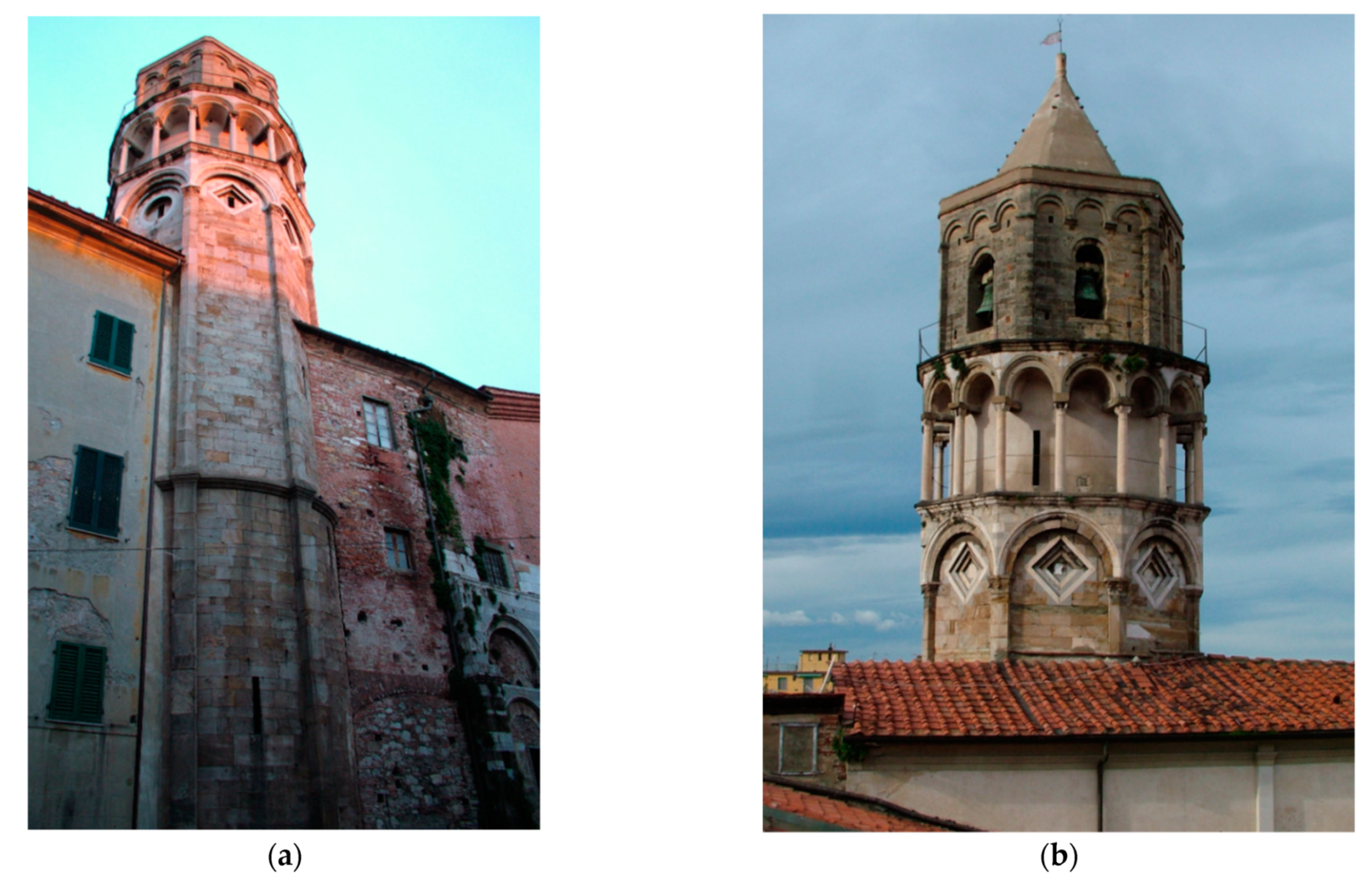
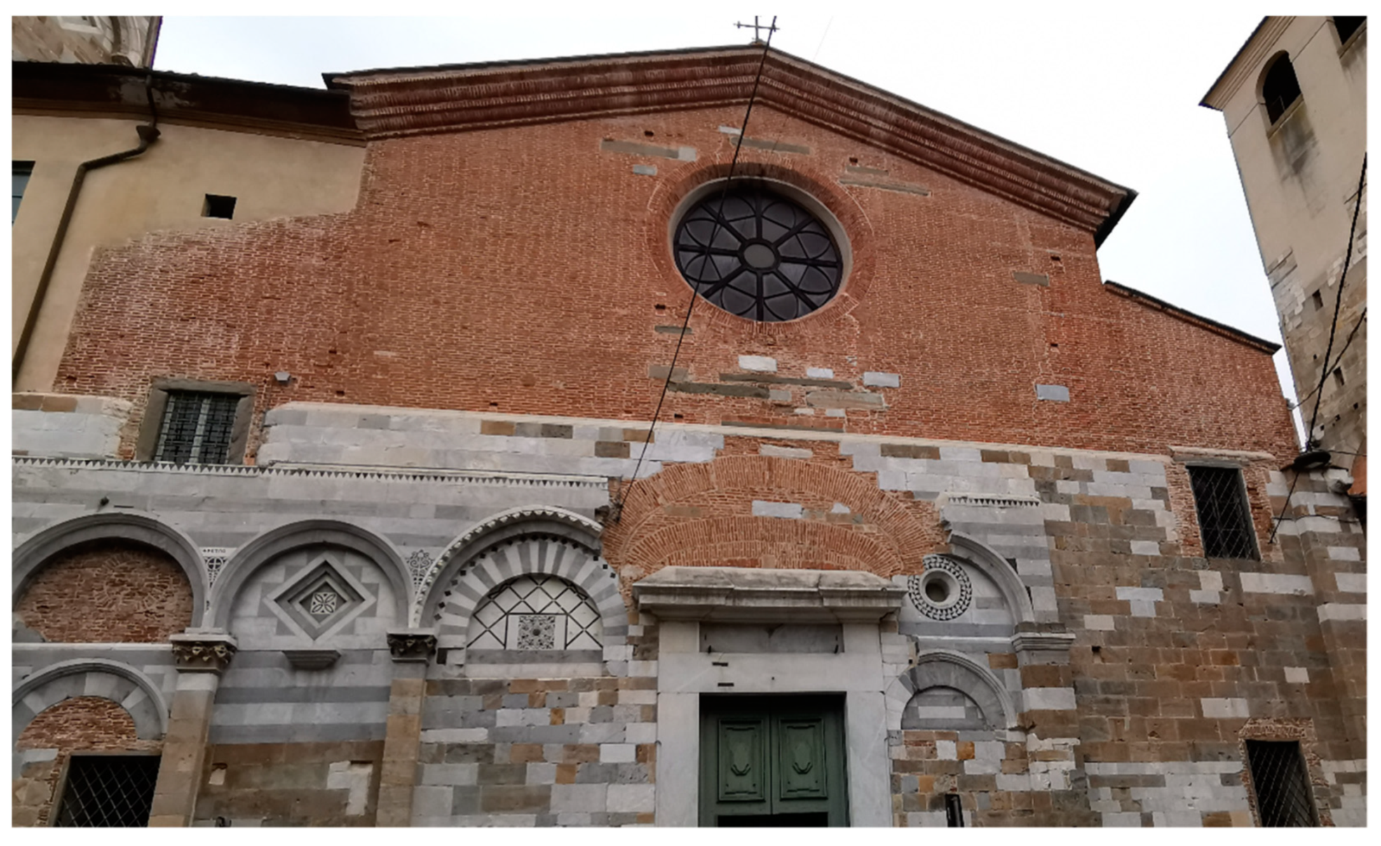
3.1. St. Nicola Church
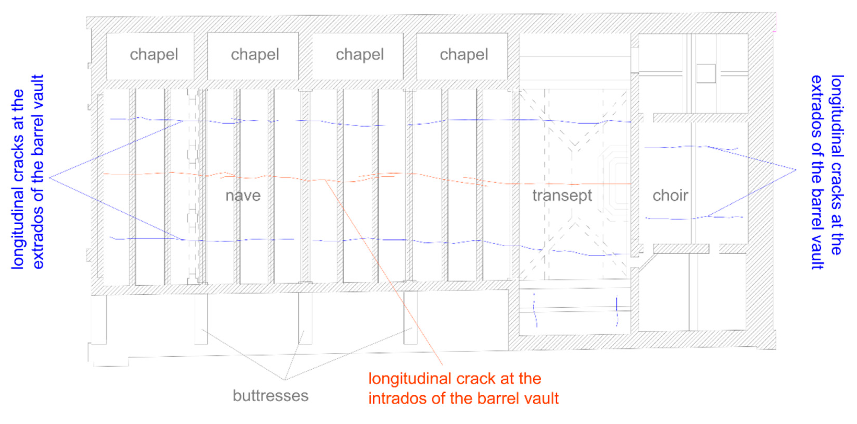
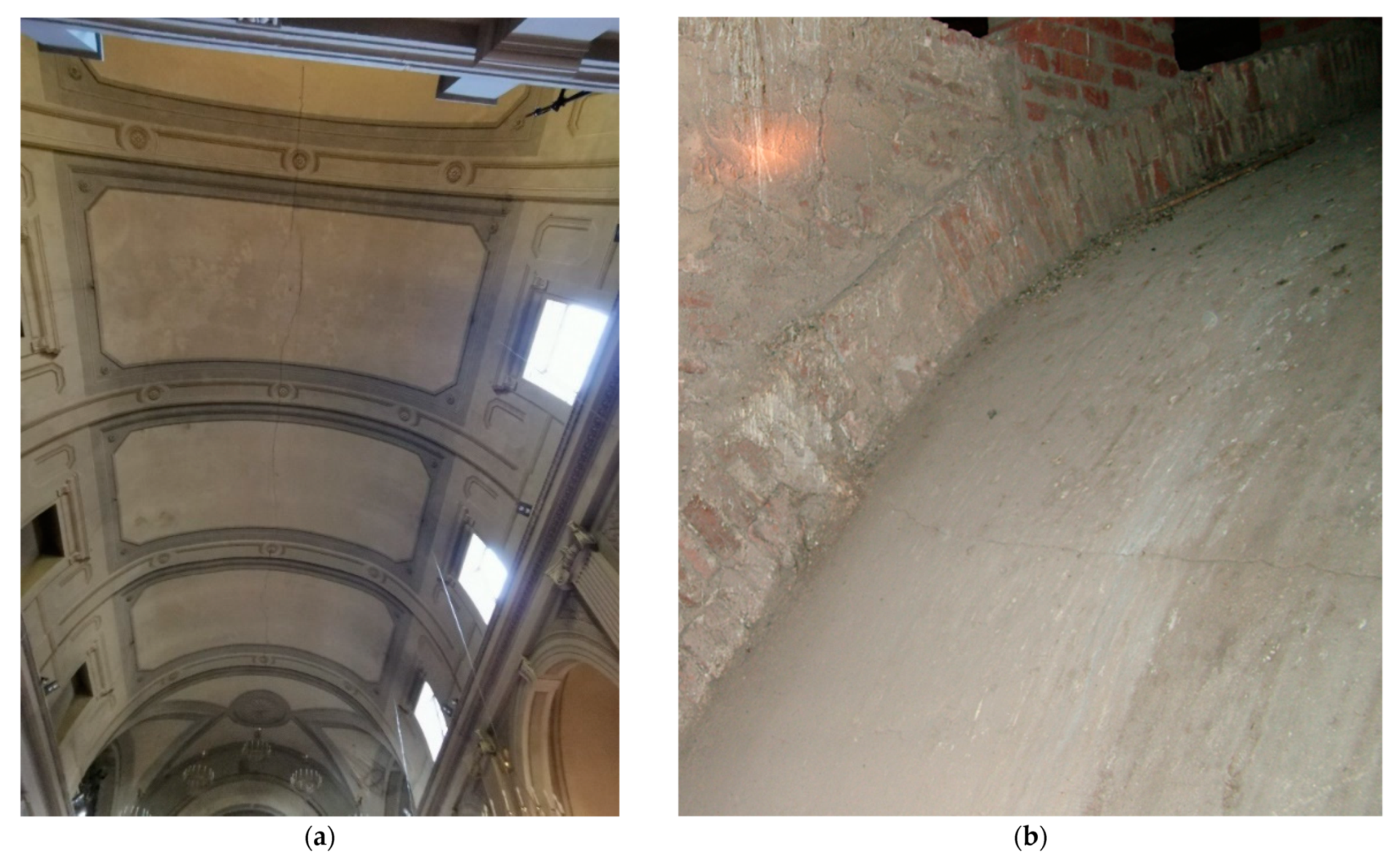
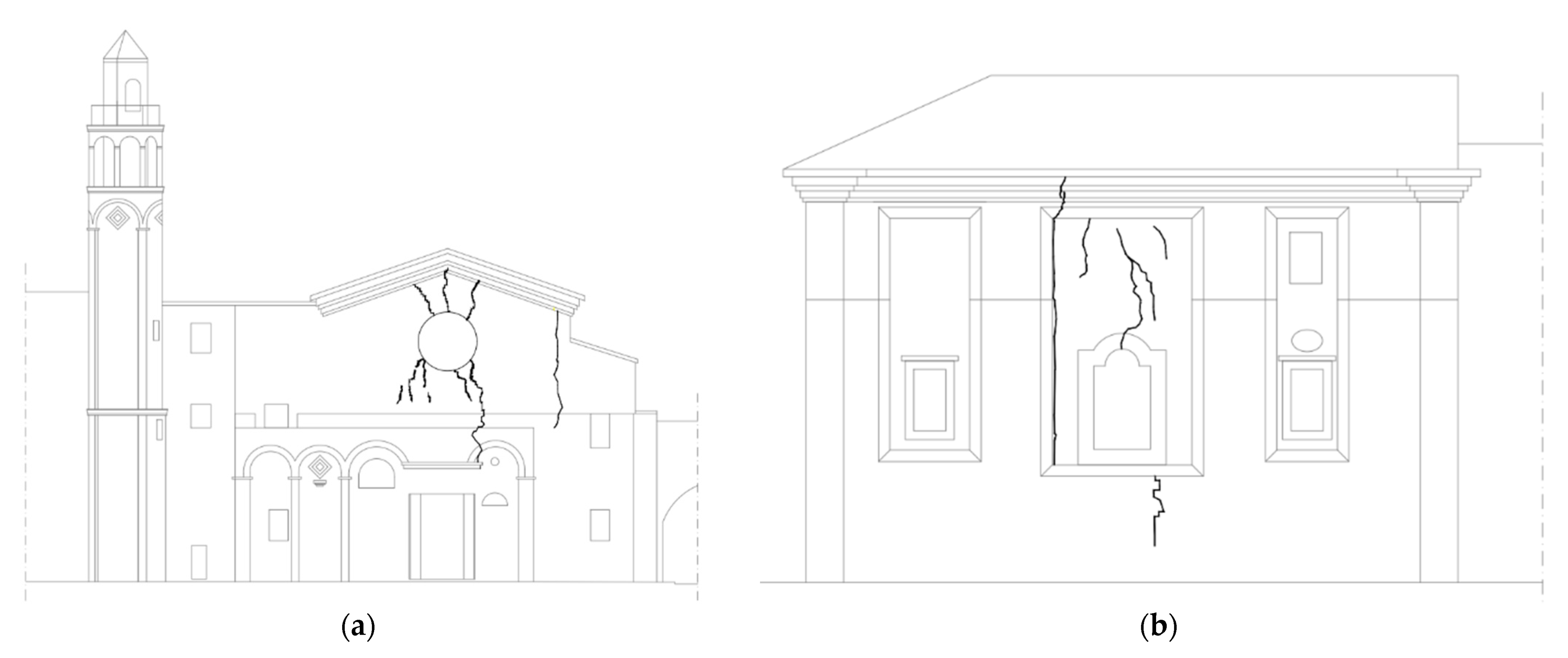
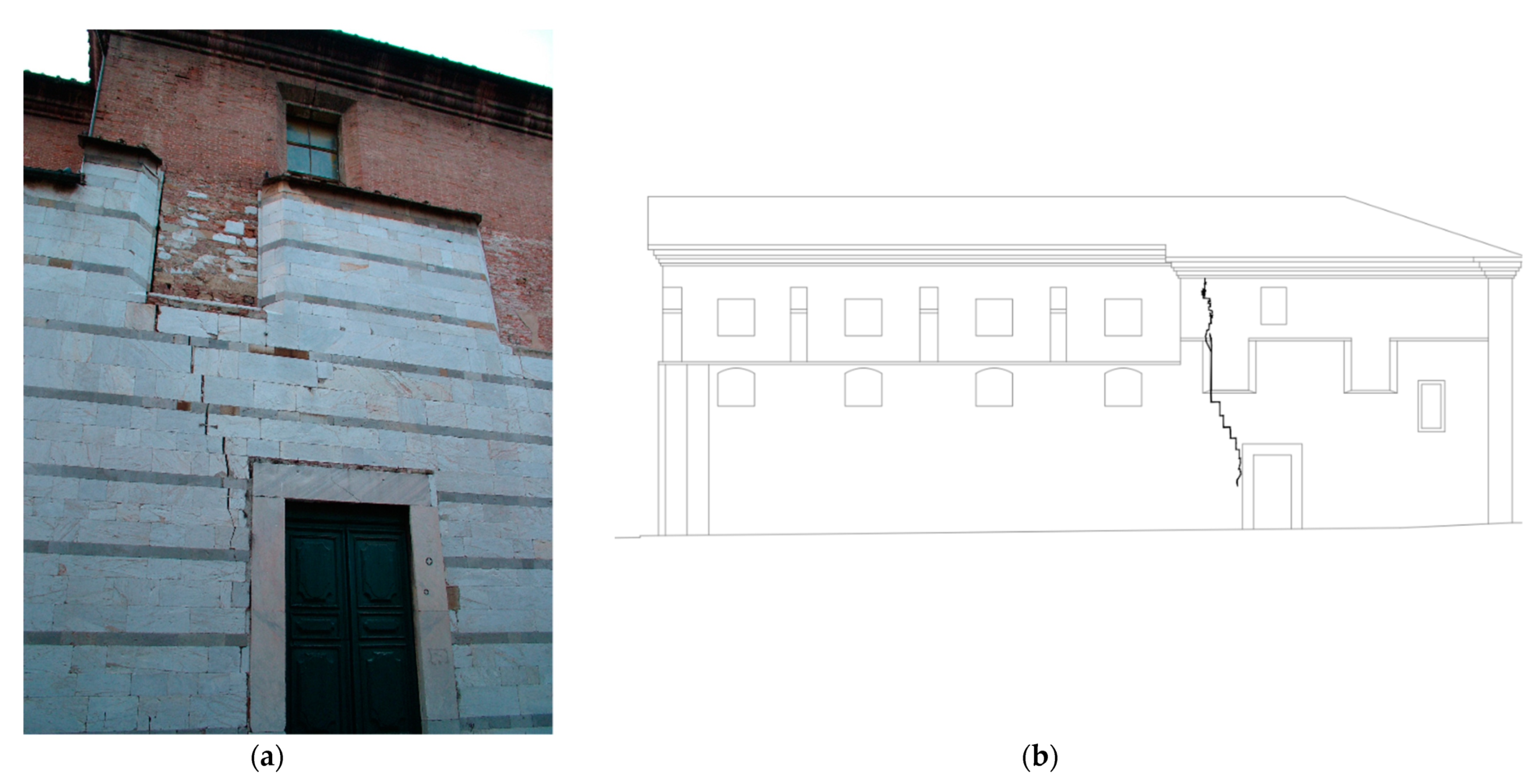
3.2. Crack Patterns and Diagnosis of the Causes
3.3. Repair and Restoration Interevntions on the Church Façades
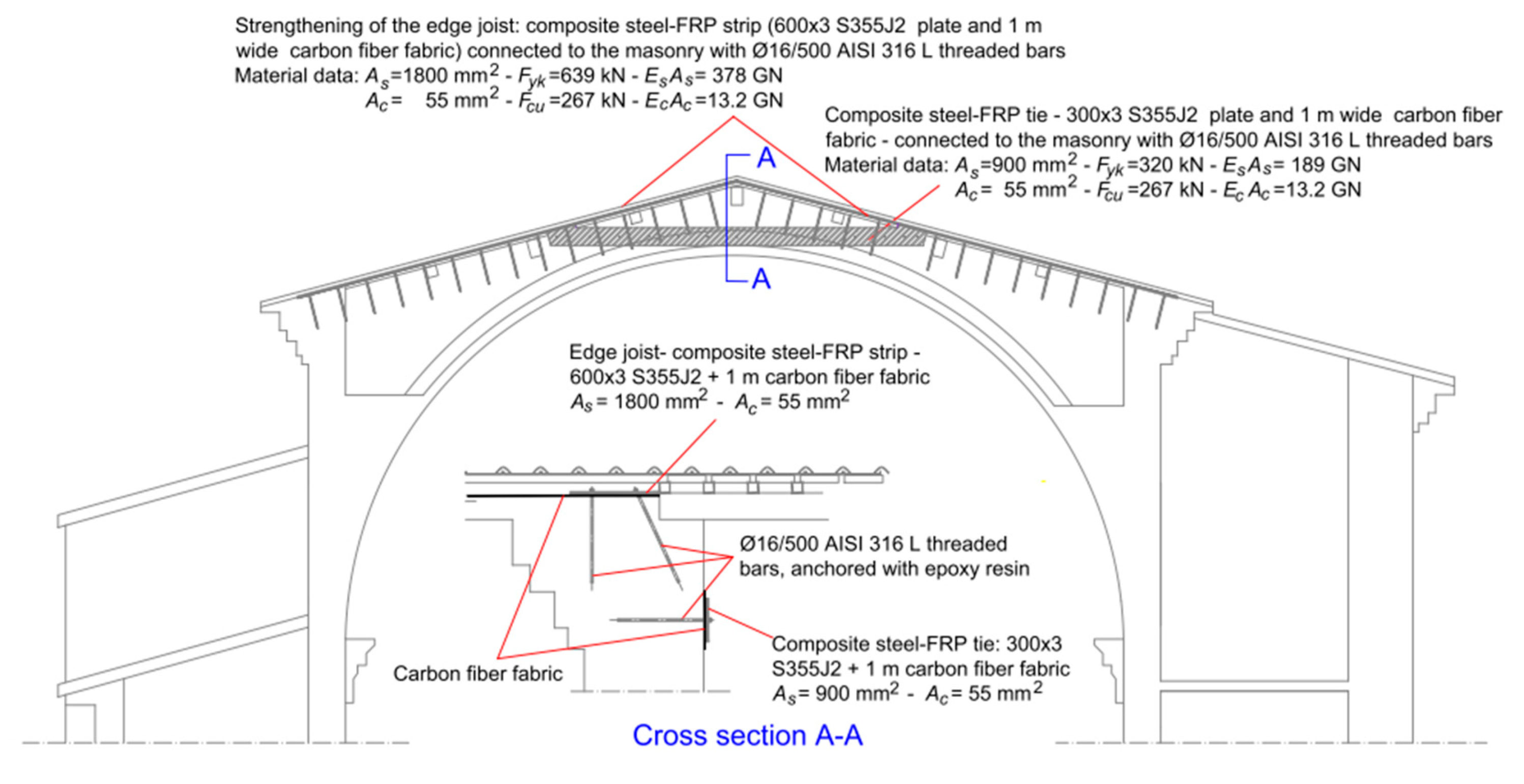
- the scope of the type A intervention was to strengthen the edge joist of the main façade, also contributing, together with the type C intervention, to restore the connection with the transverse walls,
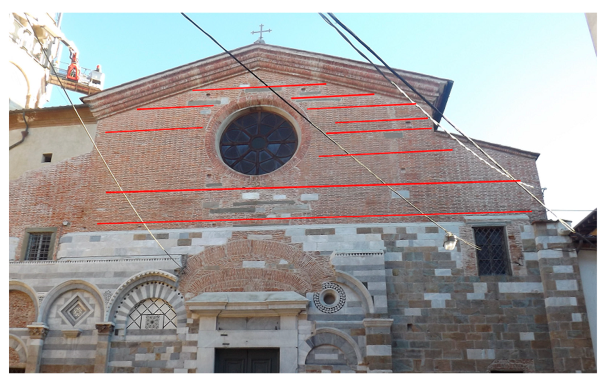
- the objective of type B intervention, based on the innovative method described in Section 2, was to efficiently bridge the cracks in the exposed masonry, preventing their reopening, also demonstrating the feasibility of the method itself,
- finally, the objective of the type C intervention was to provide an efficient connection at the top of the south façade and of the rear façade. The type C intervention was based on the application at the top of the wall of a horizontal steel plate, centered in the wall plane, duly connected with the wall itself. Considering that this kind of intervention is rather common, further details are omitted.
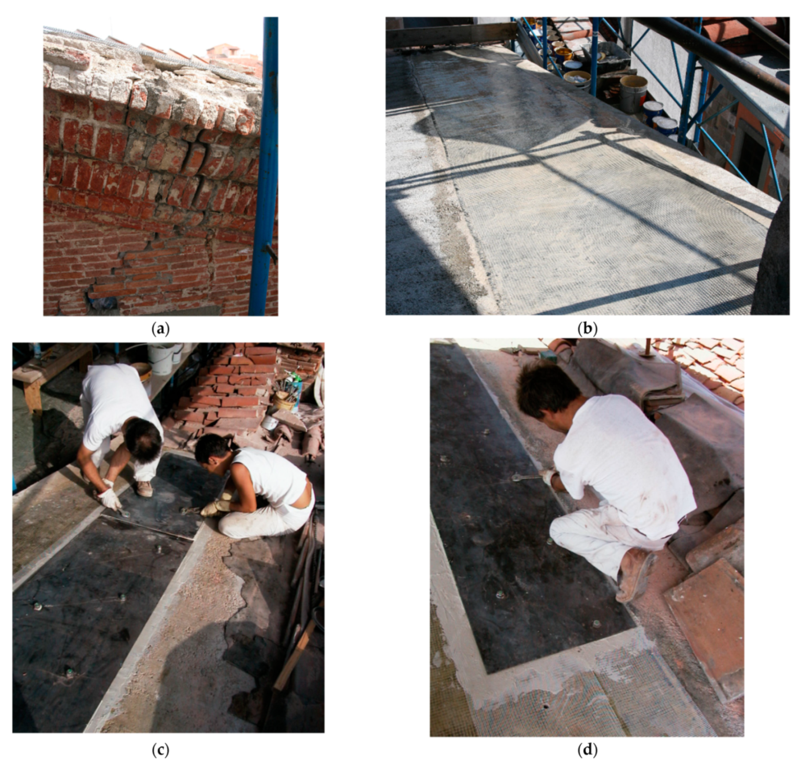
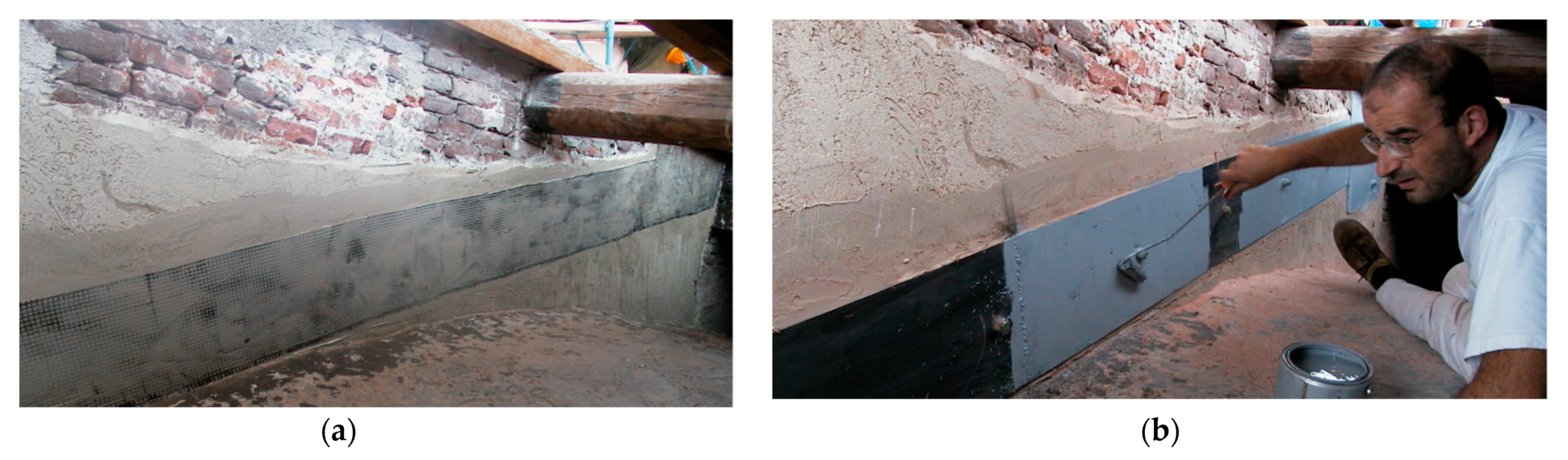
3.3.1. Type A Intervention
- Elastic modulus: ,
- Effective area: ,
- Tensile strength: .
- cleaning of the masonry surface, removing all weak and loose parts, as well as any cause that would potentially reduce the adhesion of the reinforcement,
- preparation of the top surface and its dressing by means of fine mortar,
- insertion of the connecting bars,
- application of low viscosity resin,
- addition of a bidirectional carbon-fiber fabric, and its impregnation with the low viscosity resin,
- addition of the insulating glass-fiber net,
- application of the steel plate,
- zinc coating of the steel plate.
- Steel part:
- Carbon part:
- Steel part:
- Carbon part:
3.3.2. Type B Intervention
- Area: ,
- Ultimate strength: ,
- Axial rigidity: .
3.4. Discussions
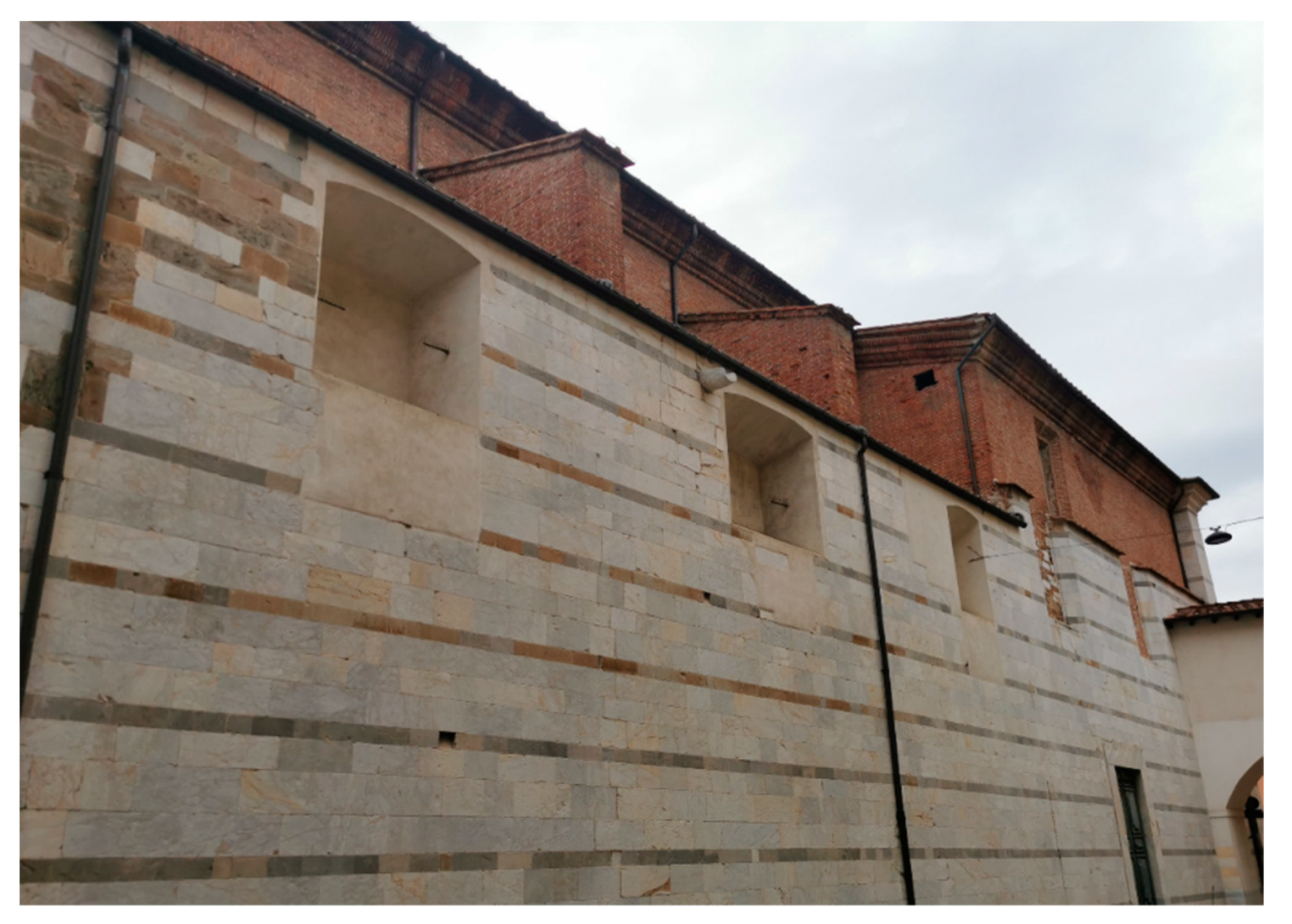
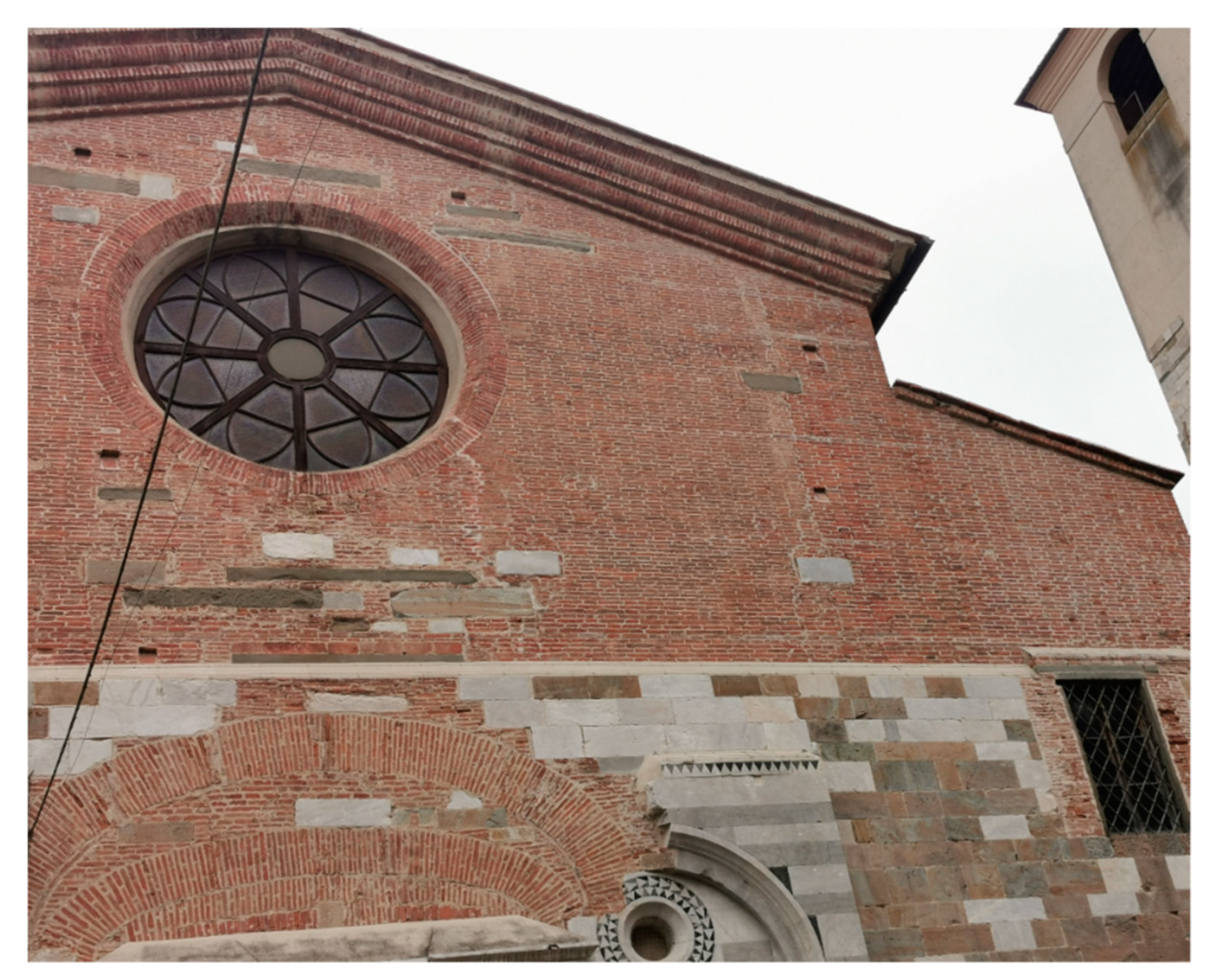
- there is no evidence of the reopening of existing cracks, or of the formation of new cracks, on the exposed masonry of the main façade, as demonstrated in detail by the photo in Figure 26,
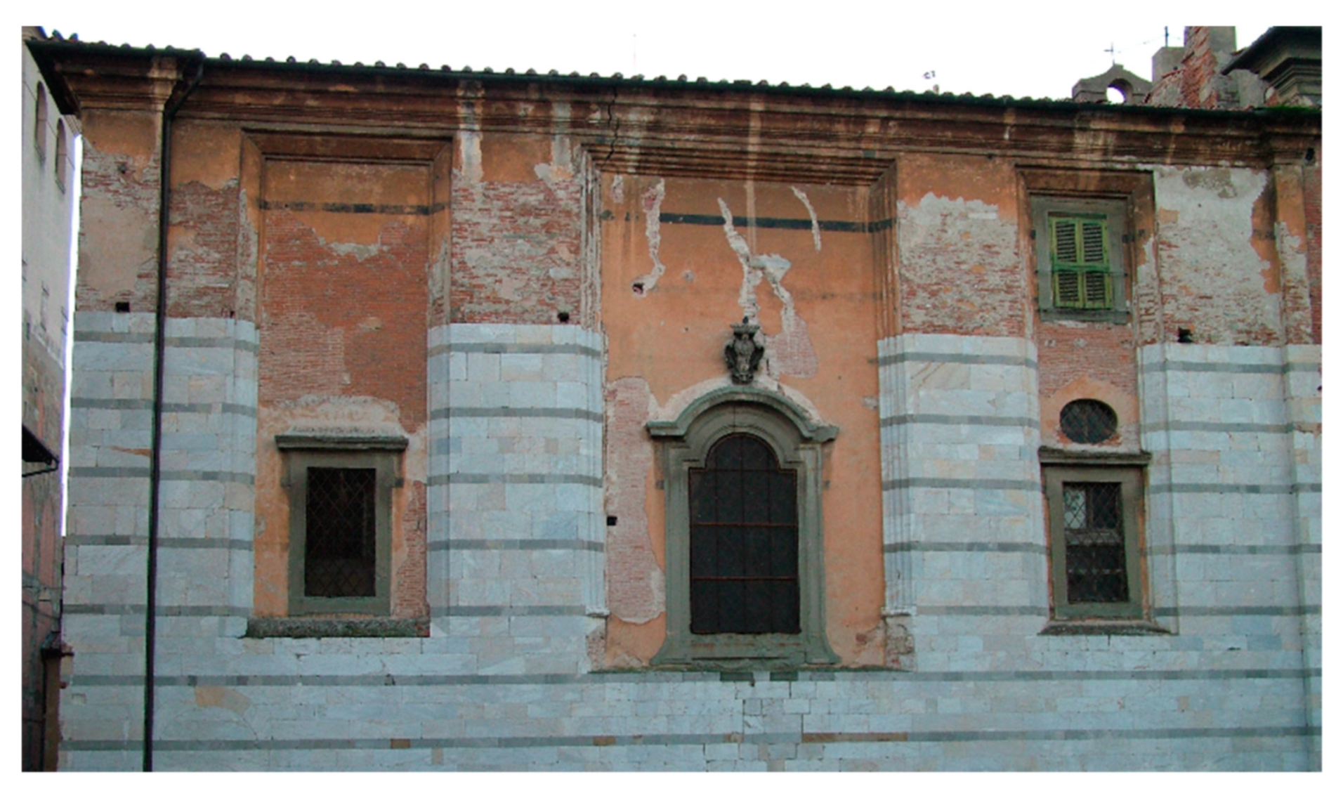
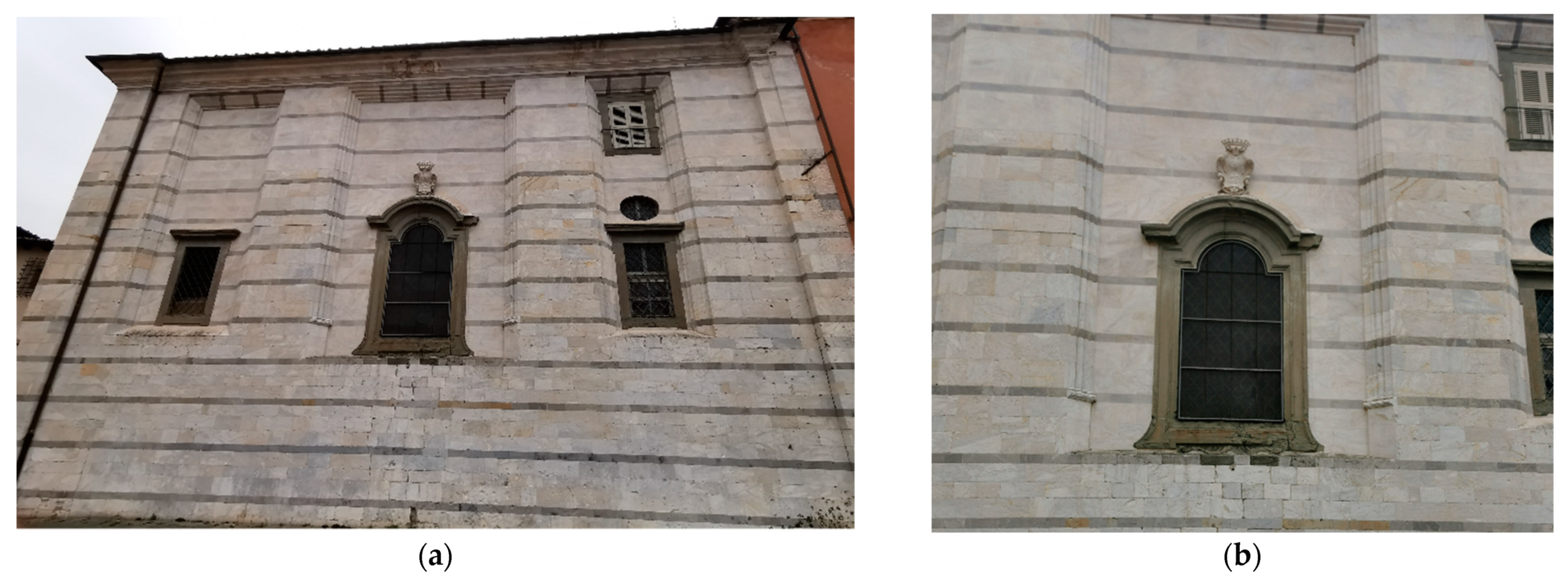
- the marble facing of the rear façade, reconstructed during the restoration works of 2005, is undamaged, while the crack pattern. previously evident in the neighborhood of the central window is no longer active (Figure 27b), and, finally,
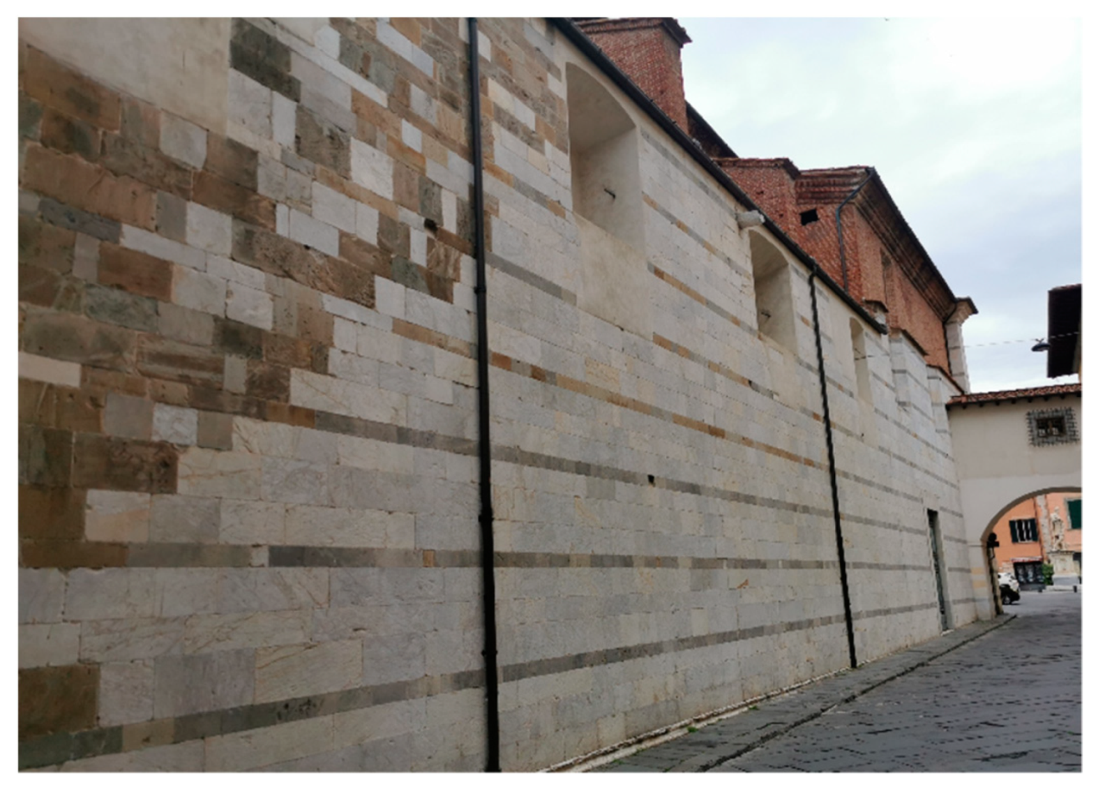
- the vertical crack of the south façade is still closed, so confirming that the differential settlement, which originated it, is nearly inactive.
4. Conclusions
5. Patents
Funding
Institutional Review Board Statement
Informed Consent Statement
Data Availability Statement
Conflicts of Interest
References
- European Committee for Standardization (CEN). EN 1990 Eurocode—Basis of Structural Design; CEN: Brussels, Belgium, 2002. [Google Scholar]
- International Organization for Standardization (ISO). ISO 2394 General Principles on Reliability for Structures; ISO: Geneva, Switzerland, 2015. [Google Scholar]
- European Committee for Standardization (CEN). EN 15898 Conservation of Cultural Heritage—Main General Terms and Definitions; CEN: Brussels, Belgium, 2019. [Google Scholar]
- European Committee for Standardization (CEN). EN 16096 Conservation of Cultural Property—Condition Survey and Report of Built Cultural Heritage; CEN: Brussels, Belgium, 2012. [Google Scholar]
- European Committee for Standardization (CEN). EN 16853 Conservation of Cultural Heritage—Conservation Process—Decision Making, Planning and Implementation; CEN: Brussels, Belgium, 2017. [Google Scholar]
- International Council on Monuments and Sites (ICOMOS). International Charter for the Conservation and Restoration of Monuments and Sites (The Venice Charter 1964); ICOMOS: Charenton-le-Pont, France, 1965; Available online: https://www.icomos.org/charters/venice_e.pdf (accessed on 26 June 2021).
- International Council on Monuments and Sites (ICOMOS). Charter—Principles for the Analysis, Conservation and Structural Restoration of Architectural Heritage, the ICOMOS 14th General Assembly in Victoria Falls, Zimbabwe, in 2003; ICOMOS: Charenton-le-Pont, France, 2003; Available online: https://www.icomos.org/charters/structures_e.pdf (accessed on 26 June 2021).
- ICOMOS International Scientific Committee for Analysis and Restoration of Structures of Architectural Heritage (I.S.C.A.R.S.H.A.). Recommendations for the Analysis, Conservation and Structural Restoration of Architectural Heritage; ICOMOS: Charenton-le-Pont, France, 2003; Available online: http://orcp.hustoj.com/wp-content/uploads/2016/04/Recommendations-ICOMOS.pdf (accessed on 26 June 2021).
- International Council on Monuments and Sites (ICOMOS). Monuments and Sites I—International Charters for Conservation and Restoration, 2nd ed.; Petzet, M., Ed.; ICOMOS: Charenton-le-Pont, France, 2004; Available online: http://openarchive.icomos.org/id/eprint/431/1/Monuments_and_Sites_1_Charters.pdf (accessed on 26 June 2021).
- International Organization for Standardization (ISO). ISO 13822 Bases for Design of Structures—Assessment of Existing Structures; ISO: Geneva, Switzerland, 2010. [Google Scholar]
- International Organization for Standardization (ISO). ISO 12491 Statistical Methods for Quality Control of Building Materials and Components; ISO: Geneva, Switzerland, 1997. [Google Scholar]
- International Organization for Standardization (ISO). ISO 12491 Information and Documentation—A Reference Ontology for the Interchange of Cultural Heritage Information; ISO: Geneva, Switzerland, 2014. [Google Scholar]
- López, F.; Lerones, P.; Llamas, J.; Gómez-García-Bermejo, J.; Zalama, E. A Review of Heritage Building Information Modeling (H-BIM). Multimodal Technol. Interact. 2018, 2, 21. [Google Scholar] [CrossRef] [Green Version]
- Croce, V.; Caroti, G.; De Luca, L.; Jacquot, K.; Piemonte, A.; Véron, P. From the Semantic Point Cloud to Heritage-Building Information Modeling: A Semiautomatic Approach Exploiting Machine Learning. Remote Sens. 2021, 13, 461. [Google Scholar] [CrossRef]
- Corradi, M.; Borri, A.; Vignoli, A. Experimental study on the determination of strength of masonry walls. Constr. Build. Mater. 2003, 17, 325–337. [Google Scholar] [CrossRef]
- Binda, L.; Saisi, A. Research on historic structures in seismic areas in Italy. Prog. Struct. Eng. Mater. 2005, 7, 71–85. [Google Scholar] [CrossRef]
- Rovero, L.; Alecci, V.; Mechelli, J.; Tonietti, U.; De Stefano, M. Masonry walls with irregular texture of L’Aquila (Italy) seismic area: Validation of a method for the evaluation of masonry quality. Mater. Struct. 2016, 49, 2297–2314. [Google Scholar] [CrossRef]
- Lagomarsino, S.; Podestà, S. Damage and vulnerability assessment of churches after the 2002 Molise, Italy, earthquake. Earthq. Spectra 2004, 20, 271–283. [Google Scholar] [CrossRef]
- Croce, N.; Croce, P.; Pelusi, M.; Taccola, R. Rehabilitation and seismic upgrading of the masonry arch bridge over the Magra river in Villafranca. Procedia Struct. Integr. 2018, 11, 371–378. [Google Scholar] [CrossRef]
- Beconcini, M.L.; Croce, P.; Marsili, F.; Muzzi, M.; Rosso, E. Probabilistic reliability assessment of a heritage structure under horizontal loads. Probab. Eng. Mech. 2016, 45, 198–211. [Google Scholar] [CrossRef]
- Marsili, F.; Croce, P.; Friedman, N.; Formichi, P.; Landi, F. Seismic reliability assessment of a concrete water tank based on the Bayesian updating of the finite element model. ASCE-ASME J. Risk Uncertain. Eng. Syst. 2017, 3, 021004. [Google Scholar] [CrossRef]
- Croce, P.; Landi, F.; Formichi, P. Probabilistic Seismic Assessment of Existing Masonry Buildings. Buildings 2019, 9, 237. [Google Scholar] [CrossRef] [Green Version]
- Croce, P.; Marsili, F.; Klawonn, F.; Formichi, P.; Landi, F. Evaluation of statistical parameters of concrete strength from secondary experimental test data. Constr. Build. Mater. 2018, 163, 343–359. [Google Scholar] [CrossRef]
- Croce, P.; Beconcini, M.L.; Formichi, P.; Landi, F.; Puccini, B.; Zotti, V. Bayesian Methodology for Probabilistic Description of Mechanical Parameters of Masonry Walls. ASCE-ASME J. Risk Uncertain. Eng. Syst. 2021, 7, 4021008. [Google Scholar] [CrossRef]
- Croce, P.; Formichi, P.; Landi, F. Influence of Reinforcing Steel Corrosion on Life Cycle Reliability Assessment of Existing R.C. Buildings. Buildings 2020, 10, 99. [Google Scholar] [CrossRef]
- Beconcini, M.L.; Croce, P.; Formichi, P.; Landi, F.; Puccini, B. Experimental Evaluation of Shear Behavior of Stone Masonry Wall. Materials 2021, 14, 2313. [Google Scholar] [CrossRef] [PubMed]
- Croce, P.; Beconcini, M.L.; Formichi, P.; Landi, F.; Puccini, B.; Zotti, V. Evaluation of Partial Safety Factors for the Structural Assessment of Existing Masonry Buildings. In Proceedings of the 18th International Probabilistic Workshop, IPW2020, Guimarães, Portugal, 12–14 May 2021; Matos, J.C., Lourenço, P.B., Oliveira, D.V., Branco, J., Proske, D., Silva, R.A., Dousa, H.S., Eds.; Springer Nature Switzerland A.G.: Cham, Switzerland, 2021; pp. 341–352. [Google Scholar] [CrossRef]
- Funari, M.F.; Mehrotra, A.; Lourenço, P.B. A Tool for the Rapid Seismic Assessment of Historic Masonry Structures Based on Limit Analysis Optimisation and Rocking Dynamics. Appl. Sci. 2021, 11, 942. [Google Scholar] [CrossRef]
- Casapulla, C.; Giresini, L.; Lourenço, P.B. Rocking and kinematic approaches for rigid block analysis of masonry walls: State of the art and recent developments. Buildings 2017, 7, 69. [Google Scholar] [CrossRef] [Green Version]
- Casapulla, C.; Argiento, L.U. In-plane frictional resistances in dry block masonry walls and rocking-sliding failure modes revisited and experimentally validated. Compos. Part B Eng. 2018, 132, 197–213. [Google Scholar] [CrossRef]
- Croce, P. Nonlinear Dynamics of Swinging Clapper Bells under Arbitrary or Resonant Forcing Functions. Appl. Sci. 2020, 10, 5528. [Google Scholar] [CrossRef]
- Stronge, W.J. Smooth dynamics of oblique impact with friction. Int. J. Impact Eng. 2013, 51, 36–49. [Google Scholar] [CrossRef]
- Housner, G.W. The behavior of inverted pendulum structures during earthquakes. Bull. Seismol. Soc. Am. 1963, 53, 403–417. [Google Scholar] [CrossRef]
- Giresini, L.; Taddei, F.; Solarino, F.; Mueller, G.; Croce, P. Influence of stiffness and damping parameters of passive seismic control devices in one-sided rocking of masonry walls. J. Struct. Eng. 2021, accepted. [Google Scholar]
- Forster, A.M. Building conservation philosophy for masonry repair: Part 1—“Ethics”. Struct. Surv. 2010, 28, 91–107. [Google Scholar] [CrossRef]
- Forster, A.M. Building conservation philosophy for masonry repair: Part 2—“Principles”. Struct. Surv. 2010, 28, 165–188. [Google Scholar] [CrossRef]
- Borri, A.; Corradi, M. Architectural Heritage: A Discussion on Conservation and Safety. Heritage 2019, 2, 41. [Google Scholar] [CrossRef] [Green Version]
- Souza, R.A.d.; Trautwein, L.M.; Ferreira, M.d.P. Reinforced Concrete Corbel Strengthened Using Carbon Fiber Reinforced Polymer (CFRP) Sheets. J. Compos. Sci. 2019, 3, 26. [Google Scholar] [CrossRef] [Green Version]
- Naser, M.Z.; Hawileh, R.A.; Abdalla, J. Modeling Strategies of Finite Element Simulation of Reinforced Concrete Beams Strengthened with FRP: A Review. J. Compos. Sci. 2021, 5, 19. [Google Scholar] [CrossRef]
- Reda Taha, M.M.; Shrive, N.G. New Concrete Anchors for CFRP Post-Tensioning Tendons. Part I: State-of-the-art Review/Design. ACI Struct. J. 2003, 100, 86–95. [Google Scholar]
- Reda Taha, M.M.; Shrive, N.G. New Concrete Anchors for CFRP Post-Tensioning Tendons. Part II: Development and Experimental Investigation. ACI Struct. J. 2003, 100, 96–104. [Google Scholar]
- Babatunde, S.A. Review of strengthening techniques for masonry using fiber reinforced polymers. Compos. Struct. 2017, 161, 246–255. [Google Scholar] [CrossRef]
- Corradi, M.; Borri, A.; Vignoli, A. Strengthening techniques tested on masonry structures struck by the Umbrian-Marche earthquake of 1997–1998. Constr. Build. Mater. 2002, 16, 229–239. [Google Scholar] [CrossRef]
- Ferretti, E.; Pascale, G. Combined Strengthening Techniques to Improve the Out-of-Plane Performance of Masonry Walls. Materials 2019, 12, 1171. [Google Scholar] [CrossRef] [Green Version]
- Nanni, A.; Tumialan, J.G. Fiber-Reinforced Composites for the Strengthening of Masonry Structures. Struct. Eng. Int. 2003, 13, 271–278. [Google Scholar] [CrossRef]
- Krzywoń, R. Steel-Reinforced Polymers and Steel-Reinforced Composite Mortars for Structural Applications—An Overview. J. Compos. Sci. 2020, 4, 142. [Google Scholar] [CrossRef]
- Aiello, M.A.; Cascardi, A.; Ombres, L.; Verre, S. Confinement of Masonry Columns with the FRCM-System: Theoretical and Experimental Investigation. Infrastructures 2020, 5, 101. [Google Scholar] [CrossRef]
- Funari, M.F.; Verre, S. The Effectiveness of the DIC as a Measurement System in SRG Shear Strengthened Reinforced Concrete Beams. Crystals 2021, 11, 265. [Google Scholar] [CrossRef]
- Ascione, L.; Feo, L.; Fraternali, F. Load carrying capacity of 2D FRP/strengthened masonry structures. Compos. Part B 2005, 36, 619–626. [Google Scholar] [CrossRef]
- Micelli, F.; Di Ludovico, M.; Balsamo, A.; Manfredi, G. Mechanical behavior of FRP-confined masonry by testing of full-scale columns. Mater. Struct. 2014, 47, 2081–2100. [Google Scholar] [CrossRef] [Green Version]
- Wiztani, J.; Zigler, R. Stress State Analysis and Failure Mechanisms of Masonry Columns Reinforced with FRP under Concentric Compressive Load. Polymers 2016, 8, 176. [Google Scholar] [CrossRef] [Green Version]
- Prota, A.; Marcari, G.; Fabbrocino, G.; Manfredi, G.; Aldea, C. Experimental In-Plane Behavior of Tuff Masonry Strengthened with Cementitious Matrix–Grid Composites. J. Comp. Constr. 2006, 10, 223–233. [Google Scholar] [CrossRef]
- Papanicolaou, C.G.; Triantafillou, T.C.; Papathanasiou, M.; Karlos, K. Textile Reinforced Mortar (TRM) versus FRP as Strengthening Material of URM Walls: Out-Of-Plane Cyclic Loading. Mater. Struct. 2008, 41, 143–157. [Google Scholar] [CrossRef]
- Oliveira, D.V.; Silva, R.A.; Garbin, E.; Lourenço, P.B. Strengthening of three-leaf stone masonry walls: An experimental research. Mater. Struct. 2012, 45, 1259–1276. [Google Scholar] [CrossRef] [Green Version]
- Gattesco, N.; Boem, I. Characterization tests of GFRM coating as a strengthening technique for masonry buildings. Compos. Struct. 2017, 165, 209–222. [Google Scholar] [CrossRef]
- Fagone, M.; Ranocchiai, G. Experimental investigation on out-of-plane behavior of masonry panels strengthened with CFRP sheets. Compos. Part B 2018, 150, 14–26. [Google Scholar] [CrossRef]
- Corradi, M.; Castori, G.; Sisti, R.; Borri, A.; Pesce, G.L. Repair of Block Masonry Panels with CFRP Sheets. Materials 2019, 12, 2363. [Google Scholar] [CrossRef] [Green Version]
- Briccoli, B.S.; Rovero, L. Towards a methodology for estimating strength and collapse mechanism in masonry arches strengthened with fibre reinforced polymer applied on external surfaces. Mater. Struct. 2008, 41, 1291–1306. [Google Scholar] [CrossRef]
- Baratta, A.; Corbi, O. Stress analysis of masonry vaults and static efficacy of FRP repairs. Int. J. Solids Struct. 2007, 44, 8028–8056. [Google Scholar] [CrossRef] [Green Version]
- Garmendia, L.; Larrinaga, P.; San-Mateos, R.; San-José, J.T. Strengthening masonry vaults with organic and inorganic composites: An experimental approach. Mater. Struct. 2015, 85, 102–114. [Google Scholar]
- Bednarz, Ł.; Drygała, I.; Dulińska, J.; Jasieńko, J. Study of Materials Behavior in a Monumental Vault Strengthened by a Carbon Net in a Mineral Matrix Subjected to Seismic Influence. Appl. Sci. 2021, 11, 1015. [Google Scholar] [CrossRef]
- Italian National Research Council (CNR). CNR/DT 200/R1/2013: Guide for the Design and Construction of Externally Bonded FRP Systems for Strengthening Existing Structures; CNR: Rome, Italy, 2013; Available online: https://www.cnr.it/en/node/2636 (accessed on 26 June 2021).
- Ascione, L.; Caron, J.; Godonou, P.; Van Ijselmuijden, K.; Knippers, J.; Mottram, T.; Oppe, M.; Sorensen, M.; Taby, J.; Tromp, L. Prospect for New Guidance in the Design of FRP, JRC Report EUR 27666, JRC99714; Publications Office of the European Union: Luxembourg, 2016; Available online: https://publications.jrc.ec.europa.eu/repository/handle/JRC99714 (accessed on 26 June 2021).
- Gutiérrez, E.; Dimova, S.; Pinto, A. Purpose and Justification for New Design Standards regarding the Use of Fibre-Reinforced Polimer Composites in Civil Engineering—Support to the Implementation, Harmonization and Further Development of the Eurocodes, JRC Report EUR 22864, JRC037836; Publications Office of the European Union: Luxembourg, 2007; Available online: https://publications.jrc.ec.europa.eu/repository/bitstream/JRC37836/eur%2022864%20en.pdf (accessed on 26 June 2021).
- European Commission. M/515 EN—Mandate for Amending Existing Eurocodes and Extending the Scope of Structural Eurocodes; European Commission: Brussels, Belgium, 2012. [Google Scholar]
- European Committee for Standardization (CEN). CEN/TC250—Response to Mandate M/515—Towards a Second Generation of Eurocodes, CEN-TC250—N 993; European Committee for Standardization: Brussels, Belgium, 2013. [Google Scholar]
- Valluzzi, M.R. Strengthening of masonry structures with Fibre Reinforced Plastics: From modern conception to historical building preservation. In Proceedings of the Structural Analysis of Historic Construction: Preserving Safety and Significance, SAHC08, Bath, UK, 2−4 July 2008; D’Ayala, D., Fodde, E., Eds.; CRC Press: Boca Raton, FL, USA, 2008; pp. 33–45. [Google Scholar]
- Valluzzi, M.R.; Modena, C.; de Felice, G. Current practice and open issues in strengthening historical buildings with composites. Mater. Struct. 2014, 47, 1971–1985. [Google Scholar] [CrossRef]
- Valluzzi, M.R.; Binda, L.; Modena, C. Mechanical behavior of historic masonry structures strengthened by bed joints structural repointing. Constr. Build. Mater. 2004, 19, 63–73. [Google Scholar] [CrossRef]
- Bosiljkov, V. Micro vs. Macro Reinforcement of Brickwork Masonry. Mater. Struct. 2006, 39, 235–245. [Google Scholar] [CrossRef]
- Sanpaolesi, P. Il Duomo di Pisa e L’architettura Romanica Toscana delle Origini; Pacini Editore: Pisa, Italy, 1975. (In Italian) [Google Scholar]
- Salmi, M. L’architettura Romanica in Toscana; Bestetti & Tumminelli: Milano, Italy, 1926. (In Italian) [Google Scholar]
- Tigler, G. Toscana Romanica; Jaca Book: Milano, Italy, 2006. (In Italian) [Google Scholar]
- Ragghianti, C.L. Architettura lucchese e architettura pisana. Critica d’arte 1949, 28, 168–172. (In Italian) [Google Scholar]
- Coroneo, R. Architettura Romanica dalla metà del Mille al primo ‘300; Ilisso: Nuoro, Italy, 1993. (In Italian) [Google Scholar]
- Willis, R. Remarks on the Architecture of the Middle Ages (Especially of Italy); Cambridge University Press: Cambridge, UK, 1835. [Google Scholar]
- Argan, G.C. L’architettura Protoromanica, Preromanica e Cristiana; Dedalo: Bari, Italy, 1978. (In Italian) [Google Scholar]
- Argan, G.C. L’architettura Italiana del ‘200 e ‘300; Dedalo: Bari, Italy, 1978. (In Italian) [Google Scholar]
- Abraham, P. Viollet-le-Duc et le Rationalisme Medieval; Vincent et Fréal: Paris, France, 1934. (In French) [Google Scholar]
- Heyman, J. The Stone Skeleton; Cambridge University Press: Cambridge, UK, 1995. [Google Scholar]


| Edge | Point ID | H [m] | Deviation [mm] |
|---|---|---|---|
| between the main façade and the south façade | 1 | 1.07 | 10.2 |
| 2 | 2.70 | 25.7 | |
| 3 | 4.28 | 40.8 | |
| 4 | 8.43 | 80.3 | |
| 5 | 12.70 | 60.4 | |
| between the rear façade and the south façade | 1 | 8.32 | −20.3 |
| 2 | 10.73 | −26.2 | |
| 3 | 13.45 | −32.8 |
Publisher’s Note: MDPI stays neutral with regard to jurisdictional claims in published maps and institutional affiliations. |
© 2021 by the author. Licensee MDPI, Basel, Switzerland. This article is an open access article distributed under the terms and conditions of the Creative Commons Attribution (CC BY) license (https://creativecommons.org/licenses/by/4.0/).
Share and Cite
Croce, P. New Frontiers of Composites Applications in Heritage Buildings: Repair of Exposed Masonry of St. Nicola Church in Pisa. J. Compos. Sci. 2021, 5, 218. https://doi.org/10.3390/jcs5080218
Croce P. New Frontiers of Composites Applications in Heritage Buildings: Repair of Exposed Masonry of St. Nicola Church in Pisa. Journal of Composites Science. 2021; 5(8):218. https://doi.org/10.3390/jcs5080218
Chicago/Turabian StyleCroce, Pietro. 2021. "New Frontiers of Composites Applications in Heritage Buildings: Repair of Exposed Masonry of St. Nicola Church in Pisa" Journal of Composites Science 5, no. 8: 218. https://doi.org/10.3390/jcs5080218
APA StyleCroce, P. (2021). New Frontiers of Composites Applications in Heritage Buildings: Repair of Exposed Masonry of St. Nicola Church in Pisa. Journal of Composites Science, 5(8), 218. https://doi.org/10.3390/jcs5080218