1. Introduction
Annular sector plates are widely employed as engineering components in civil, defence, biomedical implantation, annular segment cavities in aerospace, rail transport, and terminals of cylindrical vessels, etc. These structural components, when exposed to dynamic loads, may undergo large amplitude vibrations. In such scenarios, the linear analysis over predicts the displacement and the inclusion of non-linear terms in a strain-displacement relationship that is crucial for correct estimation of the response. The nonlinear forced vibration analysis of laminated annular sector plates provides insight into the rich dynamic behaviour that is not reflected in the linear analysis.
The exact analytical solution for the free vibration of isotropic sector plates with simply supported radial edges have been presented by Huang et al. [
1] and McGee et al. [
2]. The free vibration characteristics of isotropic thin sector plates have been investigated based on an extended differential quadrature method [
3]. The flexural free vibration frequencies have been obtained for circular and annular sectorial thin isotropic plates using sector Fourier
p-element [
4] and curved strip Fourier
p-element method [
5]. The Chebyshev-Ritz method has been employed by Zhou et al. [
6] for the free vibration analysis of isotropic annular sectorial plates. The boundary layer function has been employed by Jomehzadeh and Saidi [
7] for the analytical free vibration solution of transversely isotropic sector plates.
The free vibration characteristics of two layered laminated annular sector plates was carried out by Srinivasan and Thiruvenkatachari [
8]. The free vibration analysis of smart annular functionally graded(FG) plates has been carried out based on Kirchhoff plate Theory [
9] and first-order shear deformation theory (FSDT) [
10]. The differential quadrature method has been employed for the analysis of free vibration characteristics of laminated, composite sector plates [
11,
12]. The modified Fourier series method has been employed for the free vibration analysis of laminated composite and FG sector plates [
13]. Free in-plane vibration behaviour of FGM and orthotropic circular, annular, and sector plates has been explored based on a modified Fourier–Ritz approachby Wang et al. [
14,
15]. Liu et al. [
16] presented the free vibration analysis of a thick, annular sector plate resting on the Pasternak foundation using the three-dimensional elasticity theory and the improved Fourier series method. The discrete singular convolution (DSC) is used for obtaining the natural frequencies of isotropic, laminated composite, functionally graded, and carbon nanotube reinforced (CNTR) composite materials [
17]. The free vibration and buckling characteristics of functionally graded carbon-nanotube-reinforced composite annular sector plates have been investigated by using a variational, differential quadrature (VDQ) method [
18]. The variational differential quadrature finite element method (VDQFEM) has been employed for the free vibration analysis of the FG-CNTRC composite annular sector plates resting on the Winkler-Pasternak foundation [
19] and for plates with different cut-outs [
20]. The free vibration analysis of thick laminated circular plates with free, clamped, and simply supported boundary conditions at the outer edges have been carried out by Khare and Mittal [
21]. The 2D Fourier-Ritz method has been employed for free vibration analysis of a laminated annular/circular plate with different boundary conditions [
22]. Yuan et al. [
23] presented the exact analytical solution for the free in-plane vibration of the sector plate employing a Helmholtz decomposition. Harmonic differential quadrature (HDQ) and discrete singular convolution (DSC) is employed for the modal analysis of laminated and functionally graded sector plates [
24]. The free vibration characteristics of smart FG annular sector plates with simply supported radial edges has been investigated by employing Fourier series expansion [
25]. The frequency behaviour of the initially stressed, multi-layered CNT circular/annular plate is analysed by employing a state space-based differential quadrature method (SS-DQM) [
26]. The free vibration analysis of multidirectional FG circular/elliptical/sector plates with variable thickness has been carried out using a higher order shear deformation theory-based iso-geometric analysis [
27].
The nonlinear free vibration response of laminated annular sector plates have been investigated employing the sector
p-element method by Houmat [
28], whereas the non-linear free vibration of smart FG-CNT composite annular sector plates have been analyzed by Mohammadzadeh-Keleshteri et al. [
29]. The nonlinear post-buckling behaviour of the thin FG annular plate under the influence of thermal and mechanical load have been investigated by Aghelinejad et al. [
30]. Kumar [
31] carried out the experimental and numerical analysis of cantilever beams subjected to harmonic excitation to study the nonlinear dynamic response of the beams. The free vibration response of laminated composite conical/cylindrical shells and annular plate with a general edge constraint have been investigated by the power series method and wave-based matrix by He et al. [
32].
Most of the studies pertaining to the dynamics of annular sector plates are restricted to the free vibration investigations. The transient dynamic analysis of sectorial plates are limited to very few studies [
33,
34]. The nonlinear transient response of the annular sector plate for first few cycles has been presented, under a uniformly distributed step, sawtooth, and sinusoidal loads using Chebyshev polynomials employing a Houbolt time marching scheme by Sharma et al. [
33]. The free and transient dynamic analysis of a saturated, porous, annular sector made of of functionally-graded material employing the Rayleigh-Ritz energy formulation and Newark methods has been carried out by Babaei et al. [
34].
From the literature review, it can be inferred that there is no research available in the current literature on the nonlinear steady state, forced vibration response studies of even isotropic annular sector plates, except for the work of the author [
35] in which the nonlinear response characteristics of bimodular laminatd annular plates were investigated.
The study of the nonlinear steady state forced a vibration response of laminated composite annular sector plates, is the subject of the present work. Based on the first-order shear deformation theory, the analysis was performed using C° continuous, eight-noded quadrilateral, shear flexible element with five nodal degrees of freedom. Geometric non-linearity is included in the study using the Von Kármán assumption for small strains and a considerably large deflection. Using the modified shooting approach based on Newmark time marching, a nonlinear periodic forced vibration response is obtained in the time domain. For obtaining the post-bifurcation, unstable branches of a periodic response and the continuation scheme based on arc-length/pseudo-arc length methods were used. It is pertinent to mention that the commercially available FE softwares are unable to capture the unstable regimes of the periodic response.
The novelty of the work includes the investigation of the influence of annularity (outer to inner radius ratio), boundary conditions, and sector angle on the nonlinear forced vibration response. In order to shed light on the nonlinear forced vibration behavior of sectorial plates, the temporal and thickness variations of stress/strain, the frequency spectra of the response, and the phase plane plots are obtained. The deformed configuration of the sectorial plate at various instances during a periodic cycle is also presented, which reveal the interaction of the first and higher modes. The present analysis becomes necessary for accurate prediction of stresses and strains for the efficient and safe dynamic design of a laminated composite sectorial plate during the service as a biomedical implantation, annular segment cavities in aerospace, rail transport and terminals of cylindrical vessels, etc. where they are subjected to dynamic loads. It is apt to mention here that the linear analysis gives a conservative estimate of the displacement/stresses/strains, etc. and may lead to erroneous design.
2. Formulation
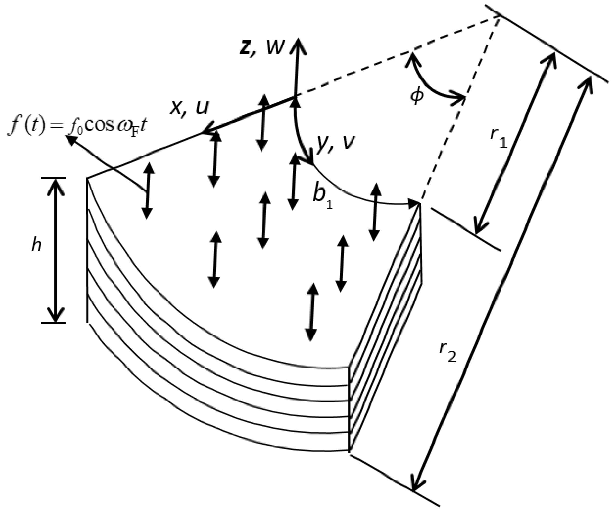
Figure 1 displays a laminated composite annular sector plate with an inner and outer radii and thicknesses
r1,
r2, and
h, respectively.
At any arbitrary point
on the sector plate, the displacement field
based on FSDT can be specified as:
where,
are the displacements of the middle surface,
and
represent the rotation of the meridional and hoop section rotations, respectively.
The nonlinear strains for the annular sector plate are taken as:
The strain field is given as:
It can be seen from Equation (3) that, in addition to the linear strain-displacement relation, the geometric nonlinearity has been incorporated through the nonlinear mid-plane membrane strain vectors. This becomes necessary if the amplitude of the deformation is the order of the sector plate’s thickness. The inclusion of nonlinearity in the formulation through the strain-displacement relation leads to more accurate restoring force dynamics as compared to linear analysis.
The stress-strain relationship is given by:
The annular sector plate comprises of
N different layers of laminas. The constitutive relations for an arbitrary layer ‘
k’ in the laminate (
x, y, z) coordinate system can be represented as:
denote the elements of the
kth layer’s transformed, reduced stiffness coefficients and are expressed in terms of the material properties and the layer’s ply-angle [
35].
The total strain energy
V is given by:
Let the annular sector plate be acted upon by a uniformly distributed external transverse harmonic force
. Then the work done by the external force (with forcing frequency (
ωF) is given by:
The total kinetic energy
T is given by:
where,
ρk is the density of the
kth layer of the laminated annular sector plate.
The total strain energy functional
V can be written as the sum of linear (
V1) and nonlinear strain energy (
V2 and
V3) functions as:
where
is the linear stiffness matrix whereas
and
represent quadratic and cubic nonlinear stiffness matrices. The elements of linear, quadratic/cubic nonlinear stiffness matrices have been defined in Reference [
36] and have not been presented here for the sake of brevity. In order to discretize the annular sector plate, an eight-noded C
0 continuous serendipity quadrilateral element consisting of five degrees of freedom is employed. The spatial interpolation of the displacement is expressed as:
The original shape functions
are smoothened using the least square method for the interpolation of the constrained strain terms for avoiding membrane/transverse shear locking [
35]. Using a standard finite element formulation, the displacement
, velocity vector
and transverse displacement
are expressed in terms of a strain displacement matrix
, the interpolation matrix
and interpolation matrix for transverse displacement
as:
is the elemental displacement vector and
is the elemental velocity vector.
Using Equation (12), the total strain energy (Equation (10)) can be written as:
The total kinetic energy is given as:
Incorporating the dissipation of energy based on Rayleigh proportional damping of the form,
(with
;
;
is the modal damping factor corresponding to the
ith mode) and applying Hamilton’s principal, the governing equation of motion can be written as:
where
represent the acceleration, velocity, and displacement vectors, respectively.
3. Solution Procedure
The solution of the governing equation of motion, to obtain the nonlinear forced vibration steady state response can be either done based on the time-domain or frequency domain methods. The direct time integration methods are unable to capture the entire nonlinear frequency response curves, especially the unstable regimes. The commonly employed frequency domain methods (harmonic/incremental harmonic balance technique) suffers from the drawback that they require participating modes to be assumed. The present work employs a modified shooting method for obtaining the nonlinear steady state response of annular sector plates. Newmark direct time integration is used to obtain the initial guess and the periodicity condition is imposed to extract the nonlinear periodic response by employing a modified shooting method. The modified shooting method preserves the banded nature of the matrices, leading to a computationally efficient scheme. The response curves post-bifurcation are estimated using an arc-length and pseudo-arc length continuation scheme [
35,
36].
In the shooting method, the state vector (
) and its solution (
) with a minimal time period is sought such that:
The solution at any time
t is obtained by integrating Equation (16) using Newmark’s direct time integration method and the Newton-Raphson iteration method after taking an initial guess of the state vector as
along with the correction
. Employing Taylor series expansion and retaining the linear terms only, we get:
Differentiating the equation of motion (Equation (16)) with respect to the state vector leads to the following.
where
represents a tangent stiffness matrix. Equation (19) is solved using Newmark’s method.
where
is step size, and
and
and are constants.
Equation (19) can be written as:
The right hand side coefficient matrix of Equation (18) is evaluated using Equations (20)–(22).
The derivative of the state vector with respect to
ωF(
and
) are obtained from the solution of
with null initial conditions for
and
.
The solution of Equation (18) is obtained iteratively by correcting the state vector until the solution converges. The simultaneous equation is solved based on the Cholesky method. The steady state response corresponding to a certain forcing frequency is obtained away from resonance. Based on the modified shooting process, the forcing frequency is increased and the steady state solution is obtained. In the modified shooting method employing frequency control, within one shooting cycle, ΔωF in Equation (18) is given a value of zero. It is noted that the shooting approach does not yield a converged stable steady state solution near the points of discontinuity in the bifurcation point neighborhood. The steady state solution in this region is obtained by switching over to the arc length/pseudo-arc length continuation method where the arc length is incremented and the converged unknown frequency is obtained.
In the arc-length continuation, using Equation (19), the arc-length increment Δ
s is specified and the increment in the frequency is obtained from:
5. Results and Discussion
The nonlinear steady state forced vibration response of a laminated composite annular sector plate was then investigated and presented. The material properties considered in the analysis are taken as (E1/E2 = 25, E2 = E3 = 1 GPa, G12/E2 = G13/E2 = 0.5, G23/E2 = 0.2, ν12 = ν23 = ν13 = 0.25, ρ = 1000 kg/m3). Based on the convergence study, the time step Δt is taken as π/100ωF.
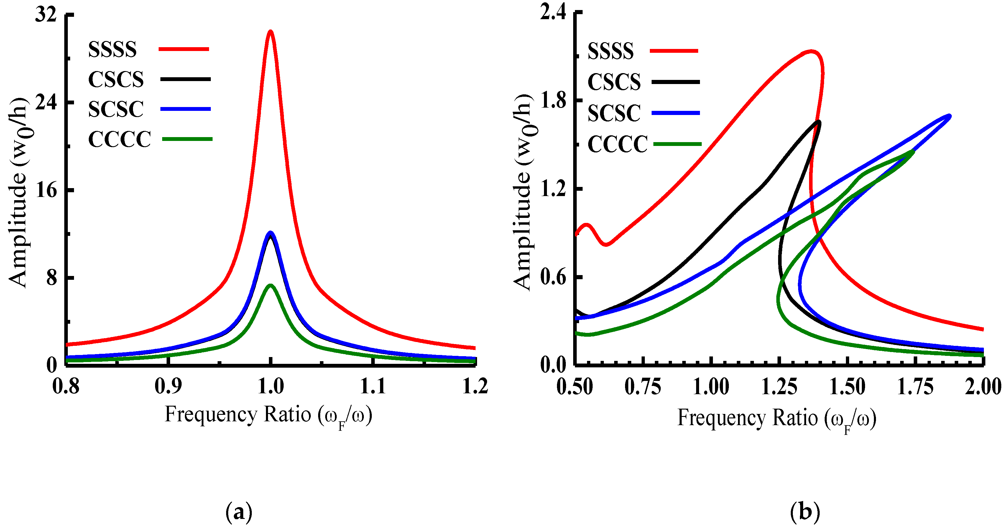
The influence of edge constraints on the linear and nonlinear steady state response of laminated composite annular sector plates ((0°/90°),
r2/
r1 = 3,
b1/
h = 100,
ϕ = 60°,
f0 = 30 Pa,
b1 = 1 m, ζ = 0.01) have been investigated and the peak amplitude at the center of the plate corresponding to variations in the forcing frequency are presented in
Figure 2. It is revealed from the linear as well as nonlinear response curves that the displacement amplitude is greatest for a laminated annular sector plate with all edges simply supported and is the minimum for all edges clamped. The annular sector plates with CSCS (radial edges clamped and circumferential edge simply supported) and SCSC (radial edge simply supported and circumferential edge clamped) boundary conditions reveal a nearly equal peak response amplitude in linear as well as nonlinear analysis. However, the forcing frequency corresponding to peak amplitude is greatest for SCSC (
ωF = 1.87
ωn1) followed by CCCC (
ωF = 1.74
ωn1) and CSCS (
ωF = 1.39
ωn1) annular sector plates. The peak non-dimensional response amplitude obtained based on the linear analysis is very large compared to those obtained based on the geometrically nonlinear analysis and this difference is greatest for the SSSS (15.83 times) boundary condition followed by SCSC (7.92 times), CSCS (7.89 times) and CCCC (5.56 times) boundary conditions.
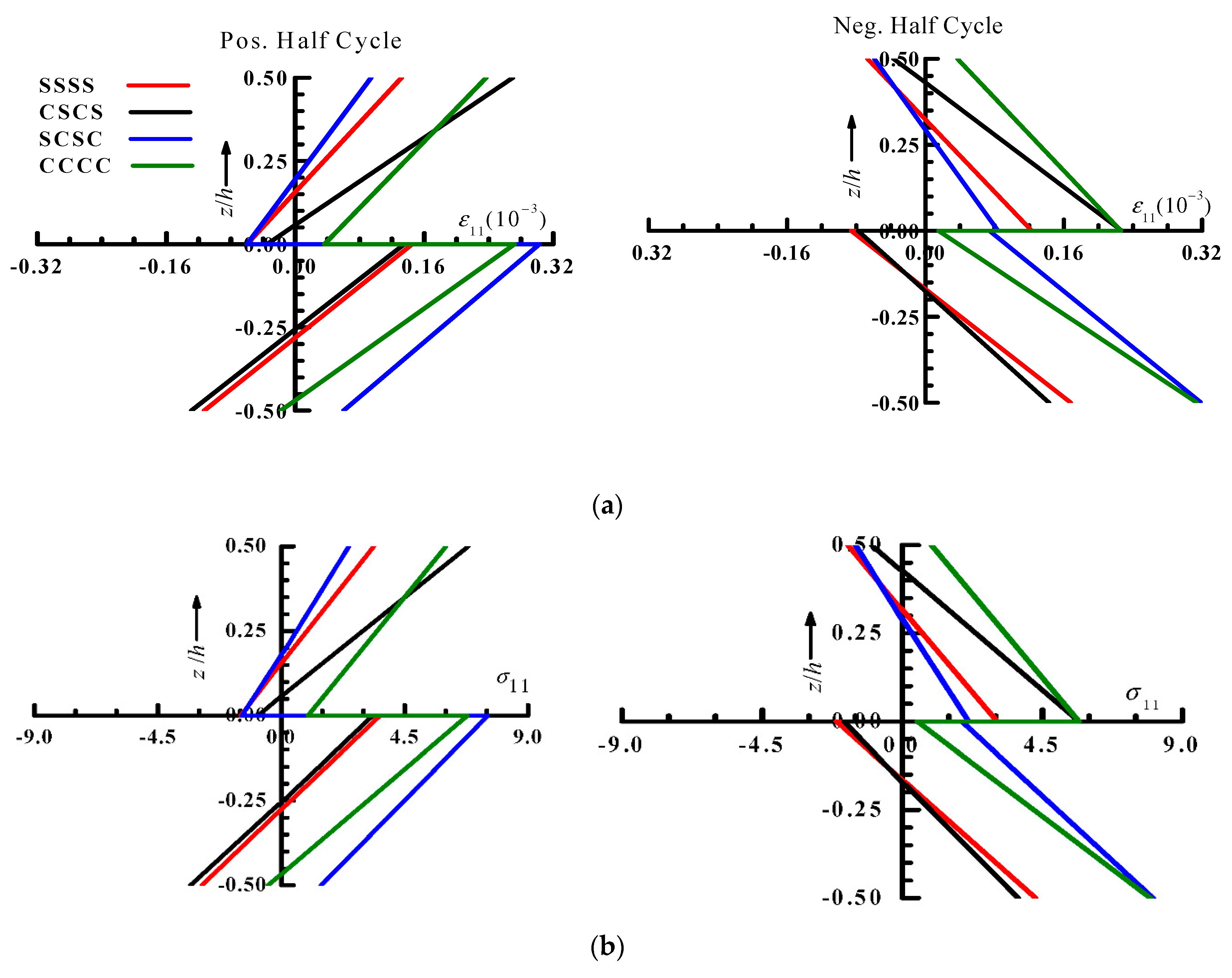
The peculiar nature of the nonlinear response for different boundary conditions (
Figure 2) have been analyzed with the help of fiber-direction normal strain and stress variations across the thickness of the laminate (
Figure 3). It can be seen from the strain/stress variations that the entire bottom layer (0°) is in tension in both the half cycles for CCCC and SCSC boundary conditions unlike CSCS and SSSS cases where the tensile portion of the bottom layer is almost 50%, leading to a greater hardening of nonlinear behavior for CCCC and SCSC laminated annular sector plates as observed in the frequency response (
Figure 2). Furthermore, the total tensile portion of laminate thickness (top and bottom layers) in both the half cycle is greatest for the CCCC boundary condition and is least for the SSSS boundary conditions, leading to the greatest peak amplitude for the SSSS boundary condition and the smallest peak amplitude for the CCCC boundary condition.
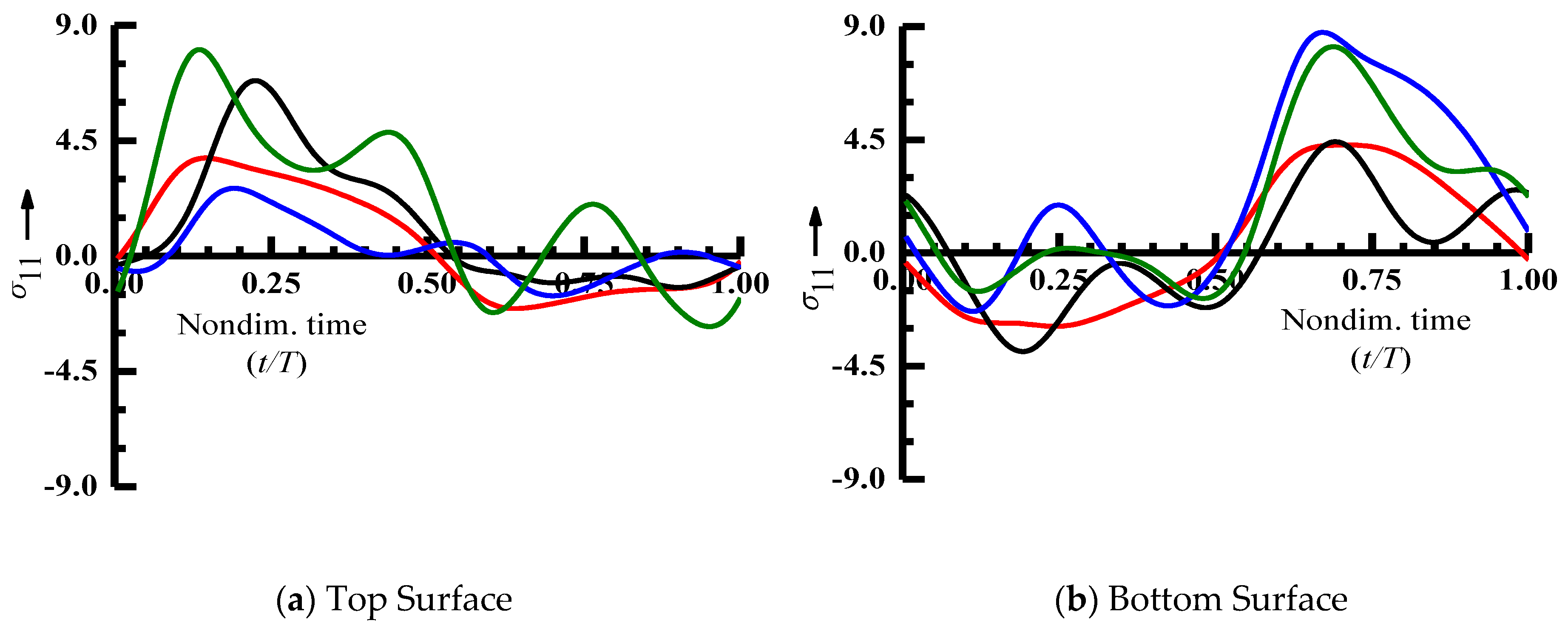
The variation of the nonlinear steady state stress (fiber-direction normal stress σ
11) within a periodic cycle corresponding to peak displacement amplitude (
Figure 2) at the center of a laminated, annular sector plate with different boundary conditions is presented in
Figure 4. It is revealed from the plots that the annular sector plate with SSSS and CSCS boundary conditions exhibit nearly equal positive and negative half cycle times with stress amplitude in tension greater than the compressive stress at the center ofboth the top and bottom surface.In case of a laminated annular sector plate with CCCC and SCSC boundary conditions, the center of top and bottom surfaces are subjected to tensile stress for a greater portion of the periodic cycle.
For all the boundary conditions, the tensile stress amplitude is greater when compared to compressive stress within a periodic cycle. The difference between the tensile and compressive stress amplitude is maximum for the annular sector plate with CCCC boundary conditions. For an annular sector plate with SCSC boundary conditions, the stress amplitude at the center of the top surface is least whereas it is at a maximum value at the center of the bottom surface compared to the other boundary conditions.
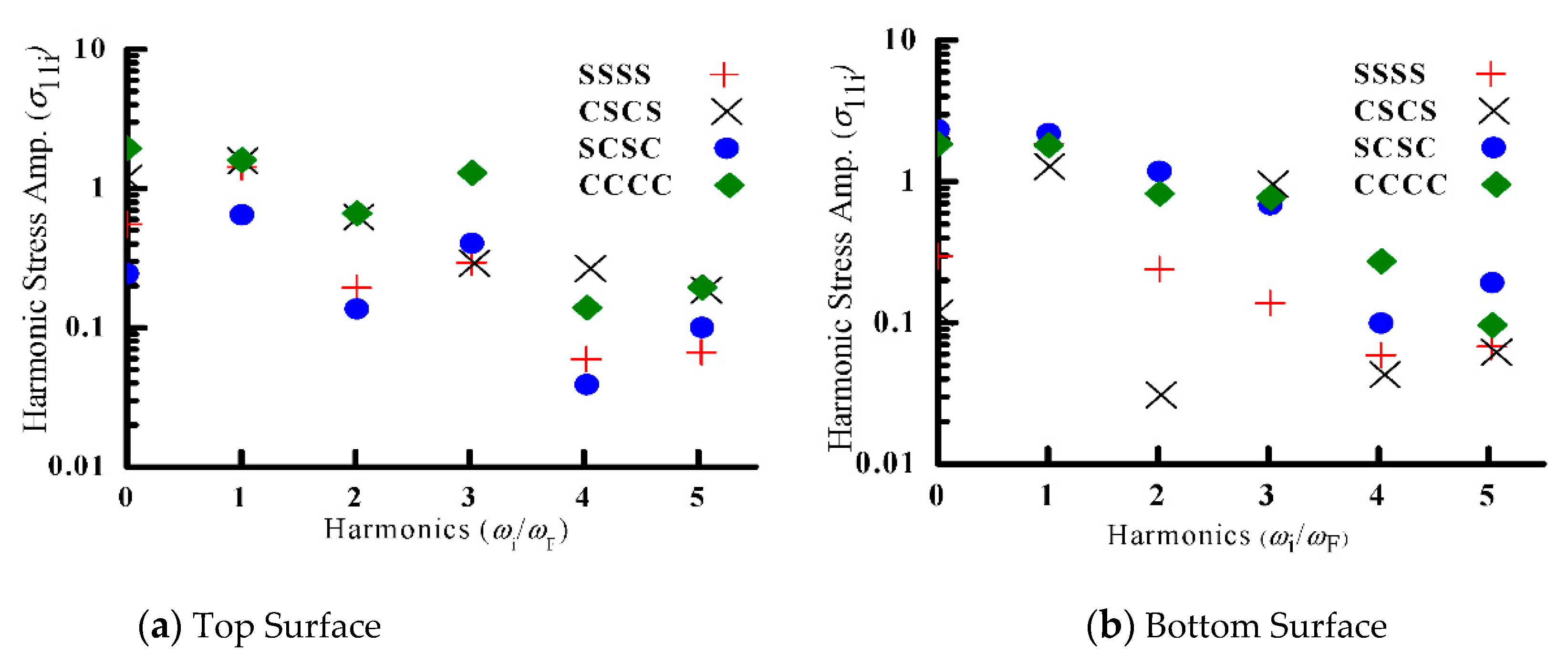
The cyclic stress variation reveals a multiple stress reversal within a loading cycle for all the boundary conditions (except SSSS), which is detrimental to fatigue design of a laminated annular sector plate. The frequency spectra of the nonlinear steady state stress (σ
11) is obtained using Fast Fourier Transform (FFT) and the results are presented in
Figure 5. The FFT reveals appreciably higher harmonic involvement in addition to the fundamental harmonics for all the boundary conditions. The third harmonic contribution is nearly equal to the fundamental harmonic at the top surface of an annular sector plate with the CCCC and SCSC boundary conditions, which is due to comparable cubic non-linear and linear restoring forces.
The role of the sector angle on the nonlinear forced vibration response of a laminated composite annular sector plate is investigated and the non-dimensional, transverse displacement at the center of the sector plate ((0°/90°),
r2/
r1 = 3,
b1/
h = 100, CCCC,
f0 = 30 Pa,
b1 = 1 m, ζ
1 = 0.01) corresponding to variations in the forcing frequency is presented in
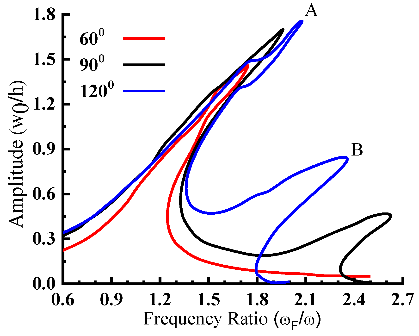
Figure 6. The nonlinear peak amplitude at the center of the sector plate increases with the rise in the sector angle. The laminated annular sector plate with sector angle 90° and 120° exhibit a prominent secondary peak in addition to the primary peak. The variations in the linear and nonlinear peak amplitude at the center of the laminated composite annular sector plate with the sector angle are presented in
Figure 7. It can be seen that the difference between the linear and nonlinear peak amplitude increases with the increase in the sector angle and this difference is 8.37 times for sector angle 120° and is 1.64 times for sector angle 30°. This is due to a greater contribution of nonlinear restoring forces with an increase in the sector angle, which limits the nonlinear peak amplitude for an increased sector angle. The percentage increase in the peak amplitude with the increase in the sector angle is significantly greater for linear analysis as compared to non-linear analysis. The non-linear steady state stress (σ
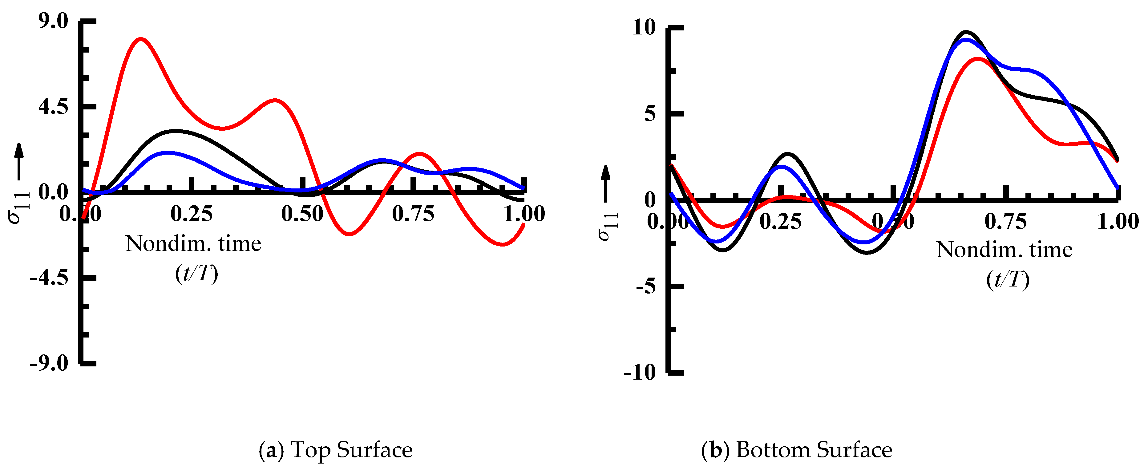
11) variation during a cycle corresponding to peak amplitude at the center of the sector plate in the frequency response curves of
Figure 6 are presented in
Figure 8. It can be seen from
Figure 8 that the center of the top surface of the annular sector plate with a sector angle of 90° and 120° is subjected to tensile stress. However, the stress amplitude is greater for the sector plate with a sector angle of 60°.
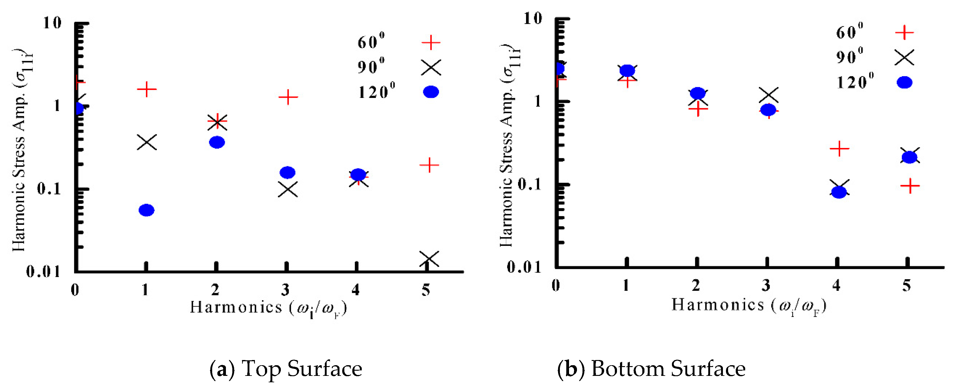
The center of the bottom surface is subjected to partly tensile and partly compressive stress during a periodic cycle with a greater tensile portion during a cycle for all the sector angles considered. The stress amplitude at the center of the bottom surface is smaller for the sector plate with a sector angle of 60° compared to a sector angle of 90° and 120°. Furthermore, there are multiple slope changes and stress reversals during a periodic cycle corresponding to a single loading cycle for laminated annular sector plates for all the sector angles considered, revealing significantly large higher harmonic contributions. The Fast Fourier Transform of the steady state stress at the center of the top and bottom surface is presented in
Figure 9. It can be seen that, at the top surface the second harmonic contribution is greater than the fundamental harmonic level for sector angle 90° and 120°, which may be due to greater involvement of quadratic nonlinear restoring forces compared to linear restoring forces. However, at the center of the top surface corresponding to the peak amplitude, the sector plate with a sector angle of 60° depicts significant odd-order harmonic contributions, which may be due to greater cubic-nonlinear restoring force contributions. The frequency spectra of the steady state stress at the bottom surface corresponding to a peak amplitude for all the sector angles considered reveal comparable second and third harmonics due to comparable quadratic and cubic non-linear restoring forces.
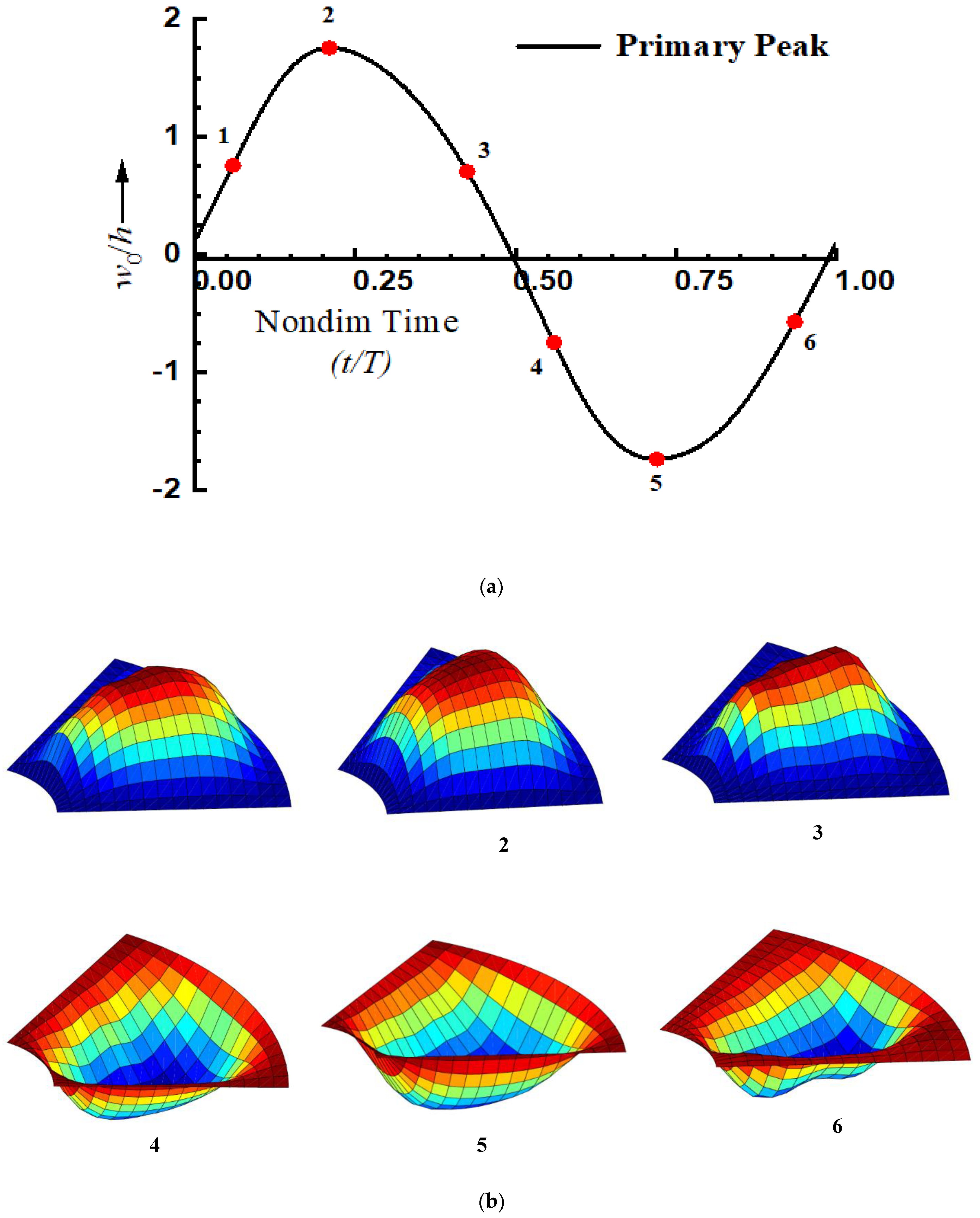
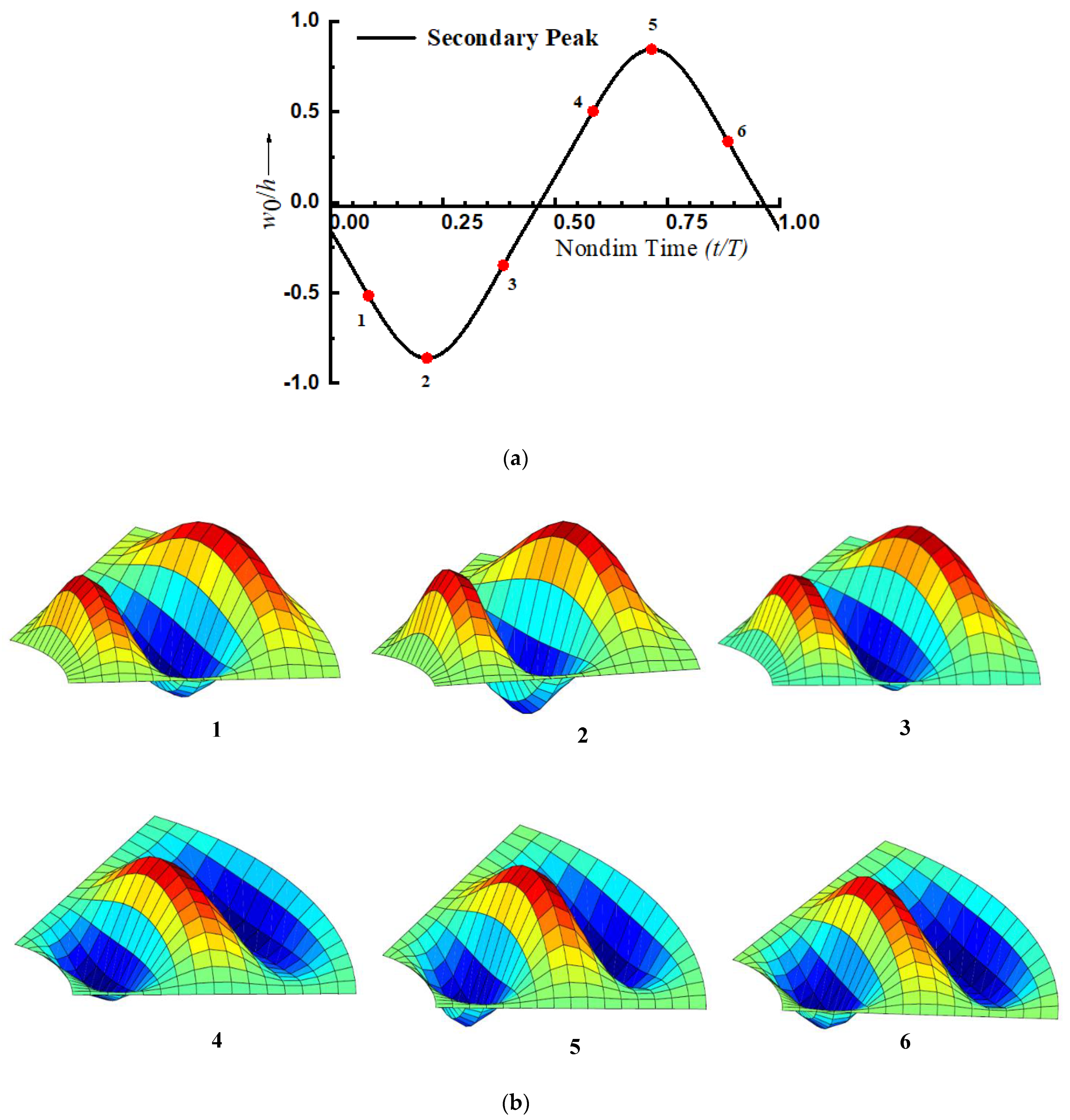
The deformed configuration of the laminated composite annular sector plate with a sector angle of 120° corresponding to primary (Point A) and secondary (Point B) peaks observed in the non-linear frequency response curve of
Figure 6 at different instants during a periodic cycle is obtained to show the modal exchange. The nonlinear steady state response corresponding to a primary peak amplitude (Point A) at the center for sector angle 120° is presented in
Figure 10a and the corresponding deformed configuration at different instants marked is shown in
Figure 10b. The nonlinear steady state response corresponding to a secondary peak amplitude (Point B) at the center for sector angle 120° is presented in
Figure 11a and the corresponding deformed configuration at different instants marked is shown in
Figure 11b. The deformed configuration corresponding to a secondary peak reveals the presence of higher modes and greater modal exchange during a periodic cycle compared to deformed configuration of the primary peak.
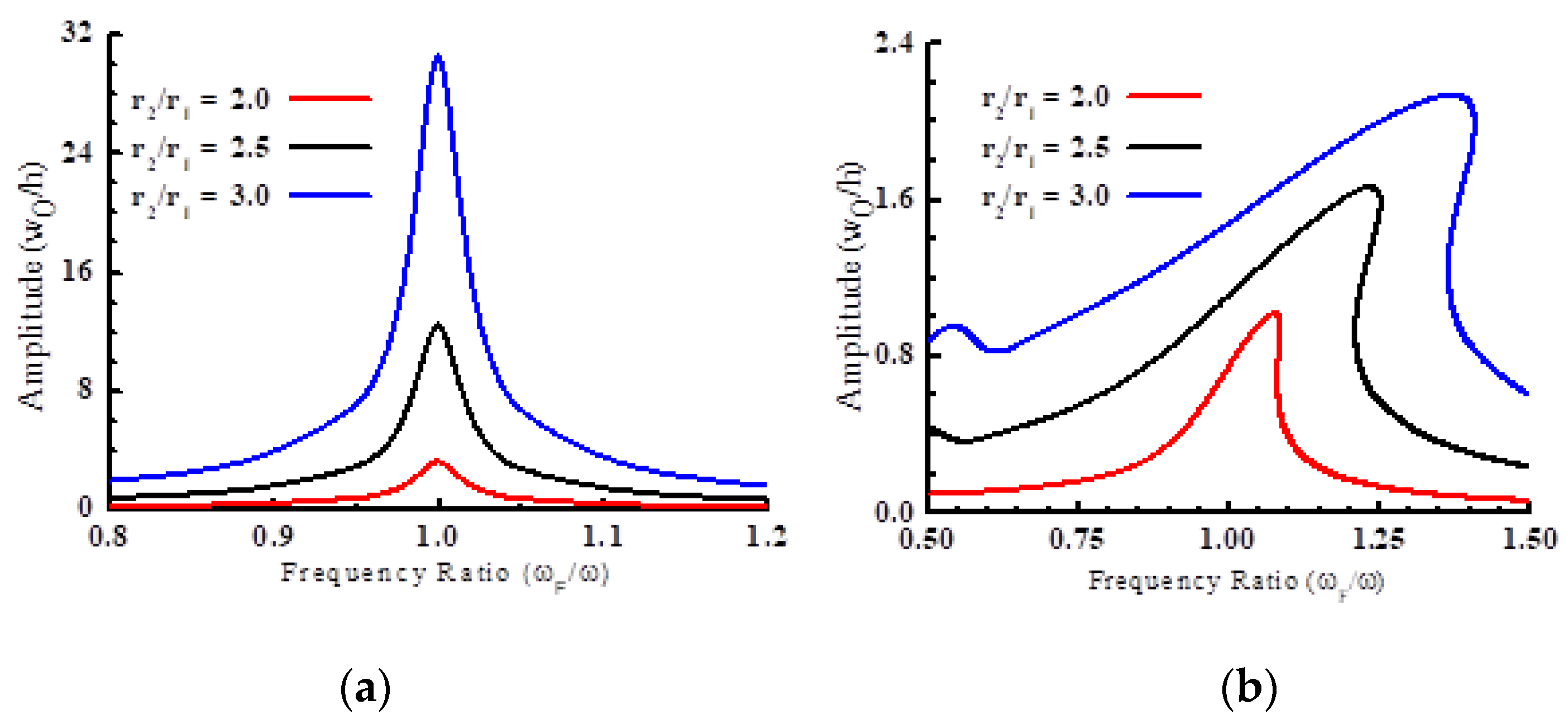
The effect of the annularity ratio (
r2/r1) on the linear and nonlinear forced vibration response is investigated next. The linear and nonlinear peak displacement amplitude corresponding to the variations in forcing frequency ratio for laminated composite annular sector plate with a different annularity ratio ((0°/90°),
b1/
h = 100,
ϕ = 60°, SSSS,
f0 = 30 Pa,
b1 = 1 m, ζ = 0.01) is presented in
Figure 12. It can be inferred from
Figure 12 that, with the inclusion of geometric nonlinearity, the frequency response curve reveals hardening nonlinearity for laminated composite annular sector plates and the degree of hardening nonlinearity increases and the peak amplitude grows with a rise in annularity (outer-to-inner radius ratio) for simply supported boundary conditions.
The forcing frequency corresponding to peak amplitude increases with a rise in the outer-to-inner radius ratio (
r2/r1) for all three cases. The degree of hardening nonlinearity for laminated, composite annular sector plates is greater for
r2/r1 = 3 followed by
r2/r1 = 2.5 and
r2/r1 = 2. It can be seen from
Figure 12 that the linear frequency also increases as the outer-to-inner radius ratio (
r2/r1) increases. The comparison of peak amplitude in the linear and nonlinear analysis reveals that the peak amplitude in linear analysis is significantly larger when compared to nonlinear analysis with the peak amplitude in the linear analysis being 15.83, 8.26, and 3.49 times the peak amplitude obtained from nonlinear analysis for
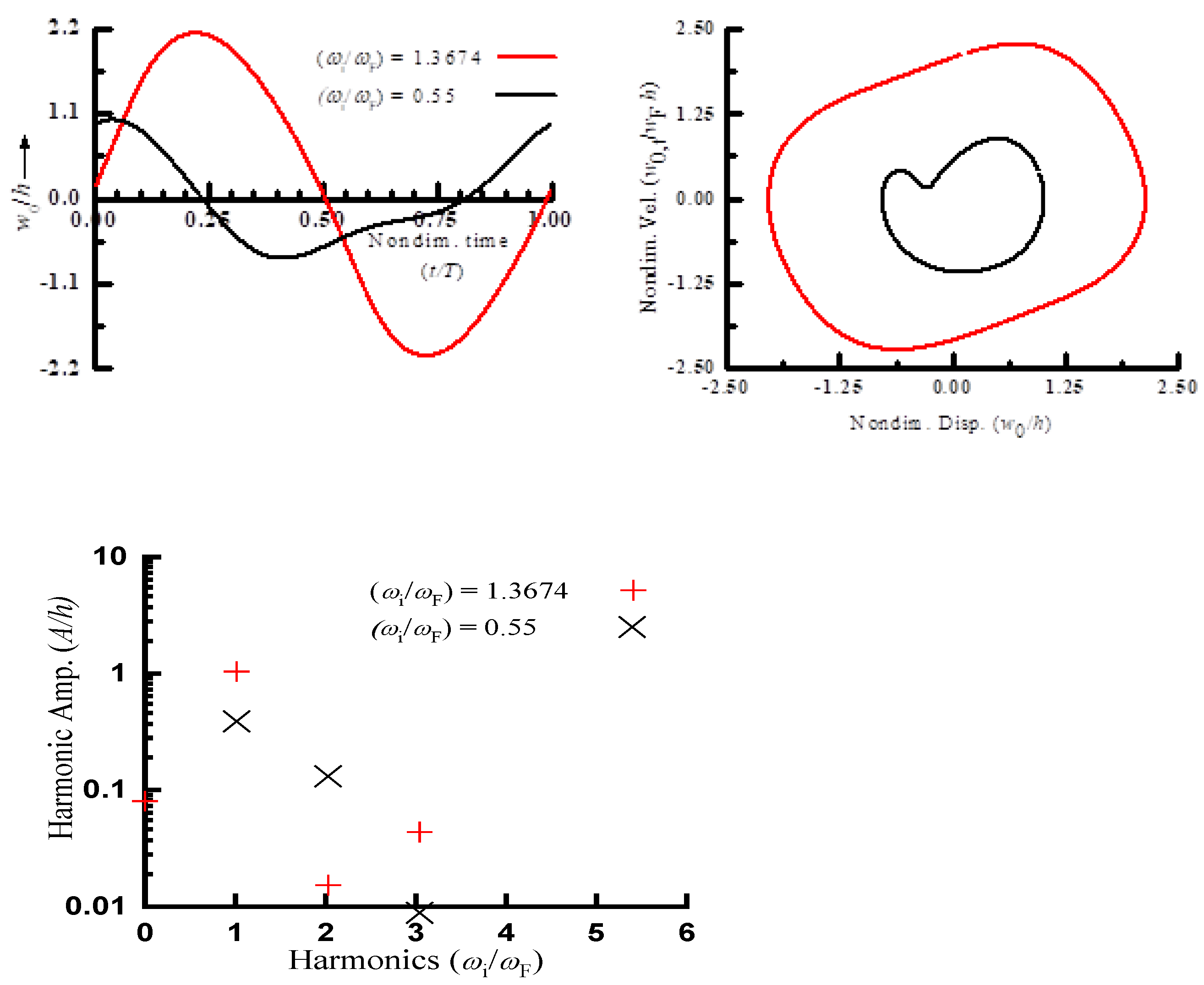
r2/r1= 3, 2.5, and 2, respectively. The reason for a spike in the nonlinear frequency response curve for annularity ratio
r2/r1= 3 corresponding to the forcing frequency ratio
ωF/
ω = 0.55 is explored using steady state response history, phase plane plot, and the FFT of the response. The results have been presented in
Figure 13.
It is revealed from the steady state response history that, at
ωF/
ω = 0.55, the center of the annular sector plate is subjected to an unequal positive/negative half cycle. Furthermore, the phase plane plot is asymmetrical for
ωF/
ω = 0.55, revealing significantly higher harmonic contributions. The frequency spectra of the nonlinear steady state displacement reveal significant even order harmonic contributions, which may be due to higher contribution of a quadratic nonlinear restoring force in addition to the linear restoring force. However, the frequency spectra at
ωF/
ω = 1.367 corresponding to peak amplitude in
Figure 12 for
r2/r1 = 3 reveal significant odd order harmonics due to a significant cubic, non-linear restoring force contributions.


