Article

Consolidation and Tow Spreading of Digitally Manufactured Continuous Fiber Reinforced Composites from Thermoplastic Commingled Tow Using a Five-Axis Extrusion System

by
Mark E. Bourgeois
and
Donald W. Radford
*
Composite Materials, Manufacture and Structures Laboratory, Colorado State University, Fort Collins, CO 80523-1374, USA
*
Author to whom correspondence should be addressed.
J. Compos. Sci. 2021, 5(3), 73; https://doi.org/10.3390/jcs5030073
Submission received: 12 January 2021 / Revised: 11 February 2021 / Accepted: 26 February 2021 / Published: 5 March 2021
(This article belongs to the Special Issue Feature Papers in Journal of Composites Science in 2020)

Abstract

:
During the development of digitally manufactured, commingled tow continuous fiber reinforced composites, consolidation force was controlled using a controlled spring force that yielded a repeatable tow width. However, the use of the extruder face to consolidate the material requires that the extruder remain perpendicular to the placement surface throughout the process. When considering more complex tool contours including sloped surfaces, more than three axes of motion are necessary to maintain the perpendicularity of the extruder tip to the surface. In this effort, a five-axis system is developed and used to demonstrate the ability to consolidate over complex contours. In addition, the nozzle face temperatures required for good consolidation and wetout result in poor tow path fidelity when complex paths are introduced. The implementation of an automated, computer-controlled localized cooling system enables both good wetout and consolidation while also enabling more accurate changes in tow path due to improvements in local tow tack. With the development of the five-axis system it is also shown that the tow width can be adjusted by rotating the existing placement nozzle to angles not equal to 90°. Thus, through a combination of controlled localized cooling and real-time control of the nozzle angle, a possible approach to control of tow width, independent of the tow placement angle and radius of curvature during tow steering, is described.

1. Introduction

A five-axis digital tow placement system is developed and used to demonstrate the ability to consolidate a high-volume fraction continuous fiber composite placed on tools with both horizontal and sloped surfaces and to utilize the multi-axis capability to adjust the placed tow width through a tow spreading operation.

Background

The current state of commercial composite manufacturing with fused deposition modeling (FDM)-based fiber placement may be considered to be the MARK TWO and MARK X from Markforged. These machines are limited to adding in-plane continuous fiber reinforcement to individual layers of thermoplastic 3D printed parts. Further, the process results in relatively low fiber volume fractions. While the addition of continuous fibers greatly increases the strength and stiffness of 3D printed thermoplastic parts, the final performance does not approach that of a traditionally manufactured, high fiber volume fraction composite material. At a research level, a number of digital approaches to incorporating continuous fiber at relatively a high fiber volume fraction, using 3D printing-based approaches, have been described.
The impregnation of a continuous reinforcing fiber tow with thermoplastic matrix materials using techniques similar to FDM 3D printing can occur in three different locations: (i) wetting out the fiber before the printing processes, (ii) wetting out the fiber in the print head, and (iii) wetting out the fiber on the component [1]. Wetting out the fiber before printing, by co-extrusion of continuous fiber and the thermoplastic matrix into a fiber reinforced thermoplastic printing filament, is a straight-forward extension of FDM printing, requiring only minor hardware changes to the 3D printer. This is the method that the MARK TWO and the MARK X use. The downside to this approach is that the fiber volume fraction is dependent on the composite filament and cannot be changed during the printing processes. Wetting out the fiber in the printhead enables the use of the least expensive form of the two constituents, dry roving and neat thermoplastic, and offers the potential of changing fiber volume fractions based on printing parameters. However, additional challenges come with wetting out thermoplastic inside the printhead, as well as handling the dry fiber in a non-rigid state. Lastly, wetting out the fiber on the component is likely the most difficult approach to achieve good results due to the added complexity of creating two systems, one that places the dry fiber and the other that places the matrix simultaneously [2].
Research groups are moving forward using the second method, creating a continuous fiber filament by combining both constituents in the placement head, with mixed success [3,4]. A system that combines fiber and plastic inside an extruder hot zone, by pulling the fiber through an extruder and then introducing the thermoplastic filament and co-extruding the resulting composite, created a composite with a fiber volume fraction of 8.6%, increasing the strength of the thermoplastic by about 400%. A slow movement speed of 1 mm/s allowed for solidification of the previously laid filament and allowed for tight corners to be taken, giving the printed material good positional fidelity [3]. Issues with the design included limited wetout of fiber and a high void percentage of the printed composite.
Alternatively, dry commingled rovings can be utilized as feedstock [5]. With these materials, the reinforcing fiber is combined with fibers of the thermoplastic matrix material by the material supplier. The commingled rovings are supplied as a dry hybrid yarn of a specified reinforcement fiber fraction. Since the commingled material is dry and the fibers move independently within the tow, the material is very flexible and since, during extrusion, only a short length of the thermoplastic matrix material flows at any given time, reinforcement fiber sliding can occur within the dry tow, better accommodating the requirements of non-linear placement paths. When using a commingled roving, the thermoplastic matrix does not have to flow long distances to wetout the fibers, making fiber wetout more effective than combining the constituents at the hot end. Commingled rovings are available with a variety of different reinforcement fibers including, but not limited to, carbon fiber and glass fiber, and different thermoplastic matrix fibers such as polyetheretherketone (PEEK), nylon, and polyethylene terephthalate (PET).
Efforts to-date to develop a continuous fiber/discrete matrix placement system utilizing commingled tow indicate that consolidation force is required in order to create a high quality, high-volume fraction composite [6,7]. Consolidation force is created by compressing the tow between the placement head and the deposition surface. In order to create a consistent force, the placement head needs to be perpendicular to the tool surface. Thus, a three-axis gantry system is limited to the production of nominally flat composite plates by this method. To improve system functionality, and enable the placement of fiber over complex contours, at least an additional two axes are needed to generate high quality, high fraction volume, geometrically complex composites. The addition of two axes to the three-axis gantry system will increase the positional fidelity of placed commingled tow on a complex tooling surface. In this research, a laboratory three-axis placement system is modified to investigate consolidation on complex contours and non-linear fiber paths and the ability to manipulate tow width using the placement nozzle inclination angle.

2. Multi-Axis Tow Placement System Development

2.1. 3D Printer

A large format gantry style 3D printer was constructed for research into the manufacture of high-volume fraction, continuous fiber reinforced thermoplastic matrix composites. The original format of the machine incorporated two separate three-axis gantries to enable investigation of the continuous commingled roving placement and neat thermoplastics in parallel. However, this arrangement limited the research performed on the equipment to a flat, horizontal surface. To address this limitation, one of the gantries was modified to enable a five-axis system that places commingled tow, while the other remains a relatively conventional three-axis FDM 3D printer. This three-axis gantry can be used to place neat thermoplastic matrix material creating tooling, or even a structural core, for more complex continuous fiber reinforced composite structures. The two gantries are independent but are calibrated so that both are on the same coordinate system/coordinate origin. To calibrate the system, the five-axis gantry is the master gantry, and the second gantry is adjusted to match the points produced by the five-axis gantry. The hot end of the three-axis gantry is capable of reaching temperatures of 500 °C. The hot end on the five-axis wrist, in the configuration used in this effort, can reach a temperature of 300 °C enabling the use of a commingled glass fiber and polyethylene terephthalate–glycol modified (PETG) fiber. The glycol modification ensures that the PETG is amorphous. The horizontal build plate, which is nominally 60 cm × 60 cm, is capable of reaching temperatures up to 300 °C. A motor on top of the Z-axis adds a rotation, the φ-axis, to the capabilities of a traditional three-axis system and an additional motor attached to a shaft of the initial φ-axis adds another degree of freedom, the θ-axis, to the system resulting in a five-axis system. A schematic of the five-axis composite placement head is shown in Figure 1.

2.2. Five-Axis System Implementation

Details of the five-axis gantry, as implemented, are shown in Figure 2. The five-axis gantry is composed of the traditional three (3) Cartesian axes with a two-axis wrist attached. The V-motor, controlling the rotation on a horizontal plane, is connected to an aluminum shaft that goes through the Z extrusion to rotate the arm that controls the W-axis rotation on a horizontal plane and holds the hot end, shown in Figure 2a. The V-motor is a high torque stepper motor which increases the amount of force that can be placed perpendicular to the hot end. The W-motor is geared down by 12:1, greatly increasing the accuracy of the W-axis and allowing a high holding torque needed to maintain the desired head angle while resisting the tension generated during the placement of the commingled feedstock. The hot end is connected to the W-axis motor with a 3D printed mount, Figure 2b, that has internal channels allowing air to flow from a compressor to two nylon tubes that direct the air flow around the nozzle, cooling the placed tow, decreasing the amount of tow shear that occurs when changing direction of the placed tow. Figure 2c shows the highest angle that the placement head can position tow in a corner without collision between the heater block and the glass print bed.

2.3. Consolidation Force

When the placement head applies consolidation pressure to the commingled roving, against a tool surface, the void content is reduced, and the processed tow takes on a rectangular shape [8]. The free body diagram for the commingled tow placement, if the tow is not already tacked to the substrate, is shown in Figure 3. The equations to find the nozzle/composite friction (P) and the composite/substrate friction (F) before any tacking to the bed occurs are as follows:
P = Pnozzle + N × μC
F = N × μS
where μC is the coefficient of friction between the composite and the nozzle, μS is the coefficient of friction between the composite and the substrate, and Pnozzle is the force required to place a composite tow. Equations (1) and (2) both include the consolidation force, N, so these equations will change in proportion to the magnitude of the consolidation force.
After the composite has been tacked down, Equation (2) changes to include the force due to the adhesive bond between the composite tow and the bed, where τ is the mean shear strength of the bond between the tow and the bed, TW is the width of the positioned tow and l is the length of the tow tacked to the surface.
F = N × μS + τ × TW × l
If the nozzle/composite friction force required to pull the fiber out of the nozzle, P, is greater than the maximum force needed to tack the fiber, F, then the composite tow pulls off the substrate. Thus, to be able to execute a change in direction, the tow must be sufficiently tacked in place to resist the pull-off forces [9].

3. Experimentation

Experiments were developed to demonstrate the challenges of generating consolidation over complex tooling contours, making high fidelity changes in tow path direction and manipulating tow width. These tests were undertaken using the custom developed five-axis system. The five-axis system was developed as a modification of an existing system used in research on digitally manufactured high-volume fraction continuous fiber reinforced composites on a flat tooling plate as described in previous sections.

3.1. Materials

The commingled feedstock used for the experiments is a continuous E-glass fiber/PETG commingled roving from Jushi America. The commingled roving has a glass fiber weight fraction of 70%, or 55% fiber volume fraction. The Tex of the roving is 2700 g per 1000 m. Stiffness information for the two constituents can be found in Table 1. A neat amorphous transparent blue PETG from ESUN, with a quoted glass transition temperature of 78 °C, was used to manufacture tooling. A sample of the commingled feedstock was tested by differential scanning calorimetry, at a heating rate of 10 °C/min, resulting in a glass transition temperature, (Tg), of 70.4 °C. Kapton tape was used as a surface material for the heated bed to enable the glass/PETG commingled tow and the neat PETG to better adhere.

3.2. Trapezoidal Tooling Geometry

The trapezoidal tool geometry, shown in Figure 4, can be defined by the height, the angle of the walls, top length, and by the width. The tool height was set to 40 mm. Two tool geometries, one with a 30° wall angle and the other with a 45° wall angle were used in the evaluation of consolidation of a sloped surface. The top length is the length of the horizontal top section of the tool and was 60 mm for these tests. The width of the trapezoidal tool was also 60 mm. The tooling was printed with a 20% honeycomb infill pattern on top of pre-placed and consolidated commingled tow, using the second three-axis printing head.

3.3. Equipment: Five-Axis Composite Placement System

Upgrading the hardware and firmware for a five-axis composite placement system was done to place continuous fiber on sloped surfaces, but still allow for the consolidation of the composite against the tool using pressure created from the tip of the nozzle. To apply consistent consolidation pressure on a tool surface, the composite placement head must be maintained perpendicular to the surface, independent of tool surface profile. More degrees of freedom than the typical three used in FDM 3D printing are required to apply consistent consolidation on both the horizontal and sloped surfaces.
Cooling air, directed as close to the point where the composite tow exits the nozzle, was expected to improve the fidelity of direction changes of placed tows [6], and to reduce the flow of the thermoplastic matrix material that resulted in the formation of flash and a variation in fiber volume fraction. Previous research had relied on a large diameter, somewhat short nozzle which reduced the ability to make rapid changes in direction as cooling was limited to several millimeters from the point the fiber exits the nozzle. To enable cooling air to contact the composite tow nearer the nozzle exit a longer, smaller diameter nozzle was developed. However, increasing the nozzle length and reducing the area of the nozzle face in contact with the tow, in combination with a continuous flow of cooling air, would likely reduce the ability to generate good consolidation. Thus, a computer-controlled cooling system was developed to allow the motion control program to switch the cooling air on and off, as needed.

3.3.1. Nozzle Geometry Development

The original geometry of the nozzle shown in Figure 5a was short, with a large flat region used to consolidate the composite strand as it was being placed on a substrate. This large flat region worked well for consolidation on flat surfaces but also resulted in a sizeable hot region at the fiber outlet which is less advantageous for creating non-linear fiber paths, as the positioned material would not remain tacked in place while turns were performed. This original nozzle was utilized in the study of consolidation on an angled plane as previous consolidation studies had used this same nozzle [8].
An updated composite nozzle was designed, shown in Figure 5b, which is longer, to improve the ability to rotate the placement head without interference with tooling surfaces. The smaller diameter allows the cooling air flow to impinge closer to the nozzle outlet enabling the tow to more rapidly become rigid, with the goal of improved fidelity of non-linear fiber paths. The increased length of the nozzle and doubling of the length of the threaded area that connects to the heater block improves heat transfer to the commingled roving, and subsequently the wetout of the reinforcing fibers in the composite tow. This longer, smaller diameter nozzle was applied to the follow-on experiments involving nozzle friction force and tow spreading.
Changing the design did have some negative effects on the composite placement process. The thick walls of the original placement nozzle offered a greater thermal mass and thus, the decrease in nozzle outlet temperature, when cooling air flow was active, was less pronounced than with the redesigned nozzle.

3.3.2. Firmware Controlled Cooling System

In previous research a system to cool newly placed composite strands was determined to be advantageous in improving positional fidelity, as tow sliding and shearing takes place during in-plane turns [6]. By cooling the continuous fiber composite, using a directed compressed air flow, the thermoplastic more rapidly becomes rigid as it is being placed and is thus capable of carrying more tension within the tow. When changing placement direction by making an arc, the fibers on the inside of the arc move a shorter distance than the fibers on the outside of the arc. Without cooling the low viscosity matrix cannot withstand this tension, allowing the outer fibers to move toward the inside of the arc. More fibers on the inside of the arc create a region that has an increased thickness and leads to manufacturing defects, as seen in Figure 6a. When continuous, directed cooling was applied during consolidation the positioned tows more closely followed the desired path, as improved tow shearing occurs, as shown in Figure 6b.
A predicted advantage of the revised nozzle design was the ability to cool the positioned tow more immediately after exiting and being consolidated by the nozzle. However, continuous cooling, as had been applied in earlier efforts, resulted in a significant decrease in the nozzle outlet temperature. The reduction in nozzle temperature, even with added heating power, negatively affected the quality of the commingled tow being placed. To address the negative effects of continuous cooling flow, a computer-controlled solution using a solenoid-controlled valve in the compressed air supply, was developed. The automated solution results in an ability to turn on, and off, cooling flow in conjunction with placement position, direction, and speed of travel. This control is predicted to maintain good interlayer consolidation while enhancing the tow positional fidelity through the ability to locally rigidize the filament as a turn is executed. To successfully implement the changes to the cooling system, hardware changes were required, as were firmware and software modifications to produce quality composites. The end effector configuration for the placement system, including the smaller diameter nozzle used in the final experiments, is shown in Figure 7.

3.4. Experimental Procedure

Three key experiments were developed to demonstrate, (i) the potential of the five-axis system to generate controllable consolidation on a complex tooling geometry, (ii) the effect of the modified nozzle, with computer-controlled cooling, on path refinement, and (iii) the effect of nozzle inclination, relative to the tool surface, on tow width. Successful implementation requires that the consolidation is consistent on both the horizontal and sloped faces of the tool, such that the tow width and thickness remain consistent on both surfaces. During direction changes in the tow path, as indicated earlier, the tow has a tendency to be pulled away from the programmed position and at the same time the tow width decreases with a corresponding increase in tow thickness. Thus, a technique that can, in real time, locally consolidate and rigidize the placed material and adjust the tow width and thickness would be valuable. The second two experiments introduce approaches to control the local path and the geometry of the positioned tow based on information gained from the first experiment.

3.4.1. Multi-Axis Fiber Placement

Glass fiber/PETG commingled roving was placed onto the horizontal top surface and the 30° and 45° sloped surfaces of the trapezoidal tools to determine the effectiveness of the five-axis modification for consolidation. The original, larger diameter nozzle was used in the consolidation study to better relate the results to previous flat plate, linear consolidation studies [13]. The programmed layer height for the placed tow was 0.3 mm while the unconsolidated tow thickness is 0.6 mm. This results in a consolidation force on the commingled tow. Based on previous trials a nominal tow spacing of 2.9 mm was used. Print speed while placing fiber was 120 mm/min, while rotations of the V- and W-axis occurred at a higher rate to decrease the total specimen manufacturing time. Hot-end temperature was maintained at 260 °C, and a nominal build plate temperature of 80 °C was utilized for the duration of the tow placement study. Each trapezoidal tool was printed onto a single layer of unidirectional continuous glass fiber reinforced PETG which had been previously positioned and consolidated from the commingled feedstock. An additional 30° wall angle trapezoidal tool was created to investigate the changing orientations of the placed fiber on flat and angled surfaces, demonstrating the functionality of the wrist on this five-axis system as well as the limitations of the large diameter extruder nozzle.

3.4.2. Nozzle Friction Force

An experiment was designed to determine the force required to pull the commingled roving through the modified, smaller diameter nozzle. This information was used to inform both the required minimum force that the wrist of the five-axis system will need to resist and the required adhesion strength of the tacked tow to the previous surface, in advance of a tow path direction change. The nozzle/composite tow friction force, P, was found by pulling the fiber, at right angles to the nozzle, as would be the case during placement and consolidation, at different speeds and temperatures. The test was accomplished by attaching the composite tow to a load cell, as shown schematically in Figure 8, and moving the composite placement head at a known rate away from the load cell. Three factors were investigated: (i) print speed, (ii) heater block temperature, and (iii) the effect of active cooling.

3.4.3. Tow Width Manipulation

As a dry tow moves over a surface, either cylindrical or round, the individual fibers will want to contact the surface and will arrange themselves to do so, spreading the tow in proportion to the distance the fiber travels on the surface curvature [14]. Composites with wider/thinner tows can exhibit better fiber packing, lower void contents, and improved mechanical properties [15]. With the additional axes of motion, the placement head can be manipulated to increase the relative nozzle angle, θ, to the tool surface, increasing the distance the fibers travel on the round tip of the nozzle, thus potentially increasing the tow width. Conservation of volume would suggest that the tow thickness will then decrease in a controllable manner. Tow spreading by this approach is somewhat separate from the applied consolidation pressure and has the potential to be applied locally during changes in the direction of the tow, to maintain a predetermined tow width. In addition, tow spreading during placement has the potential to improve fiber wetout [16].
An experiment was designed to test how much a tow of commingled material would spread in response to composite placement head nozzle inclination angle, θ. During the experiment, the placement head followed a linear path while the head rotation angle, θ, was controlled around the point the nozzle would contact the newly placed composite tow, shown in Figure 9, thus maintaining a constant height of the nozzle above the tool surface. Placement head angles, θ, of 0°, 5°, 10°, 15°, 20°, 25°, and 30° were investigated to determine the amount of tow spreading that would occur when placing the fiber on a rigid surface. Four layers of commingled roving were placed at each angle to give a more measurable difference of tow reshaping.

4. Results and Discussion

4.1. Multi-Axis Fiber Placement

The positioning of the printhead and nozzle for placement on the 30° angled surface of the trapezoidal tool is shown in Figure 10. The wrist can be seen, rotated to position the nozzle perpendicular to the tool surface. It is also clear that the nozzle is no longer directly in line with the Z-axis of the system which places a lateral load on the Z-axis components.
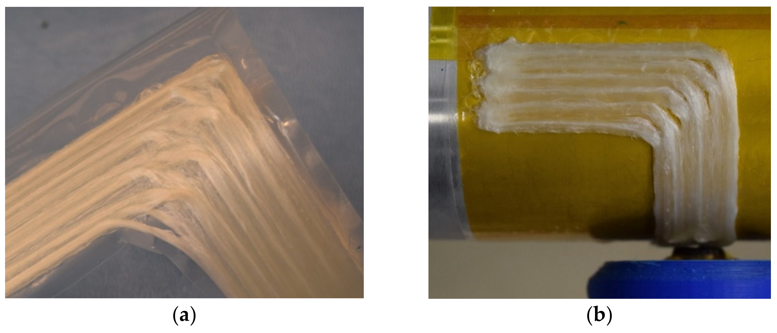
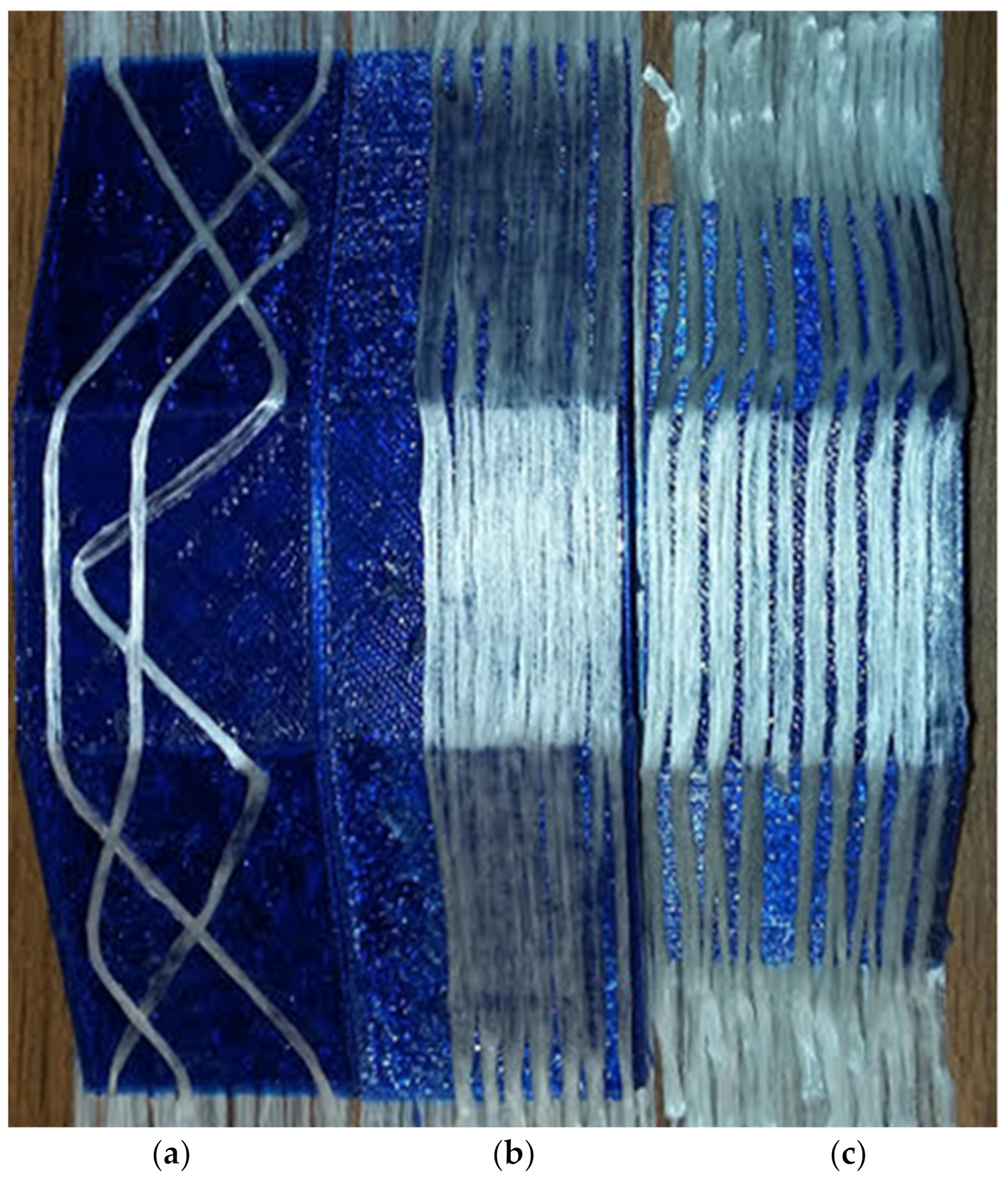
Placement and consolidation of commingled tow, following non-linear and linear paths, over the complex trapezoidal tools, is shown in Figure 11. These trials were not meant to be used to optimize tow placement parameters, but rather, to investigate areas where equipment modifications were effective and where unexpected issues might arise. The non-linear tow placement paths shown in Figure 11a demonstrate the challenges involved in simultaneously maintaining consolidation pressure and changing direction, even on the top horizontal surface. The results related to the non-linear placement paths will be discussed in conjunction with results of the automated localized cooling and tow spreading in the following section. The linear tow placement in Figure 11b on the 30° surface suggests that maintaining the nozzle perpendicular to the surface as the profile changes is successful, as the tow width is visually similar on the sloped surfaces and the top horizontal face. However, there is clearly a tow width change between that on the 45° sloped face and on the horizontal top surface, shown in Figure 11c.
The degree of consolidation on the 30° angled face, Figure 11b, is considered equivalent to that on the top horizontal surface as both show similar tow width and optical characteristics. Previous efforts have shown that well-consolidated glass fiber/PETG specimens are translucent, while poorly consolidated commingled tow will look opaque due to a difference in the optical properties of the matrix, the glass, and trapped air [7,17]. Placement on the sloped surface of the 45° trapezoidal tool did not result in consolidation of the same quality as that seen on the 30° tool. The difference seems to be related to the higher angle of the sloped tool face and radial deflection of the V- and W-axis, when pulling tow. For the 45° angled surface, the reduced consolidation force results in an increase in the tow thickness, a reduction in tow width, and a corresponding increase in the tow spacing. The increase in tow separation and tow thickness is consistent with a significant print head displacement while moving up the sloped surface. This is an indication that lateral deflection in the Z-axis, along with possible rotation in the wrist, θ, is occurring. However, since the consolidation on the horizontal surface is unaffected, the bending of the Z-axis is believed to be of greater concern than the wrist rotation under load. To overcome this problem, a more rigid gantry system will be required for future activities utilizing the five-axes system.

4.2. Non-Linear Placement Paths

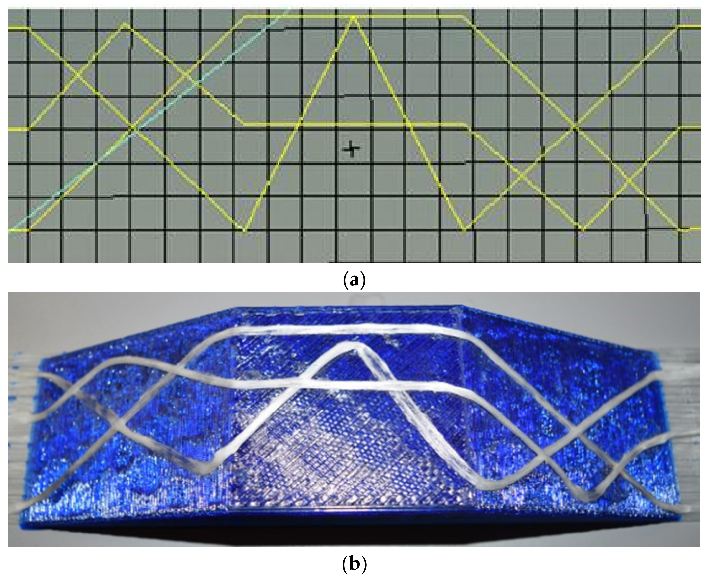
The result of the trial demonstration of non-linear placement paths is shown in Figure 12. The programmed placement paths are shown in Figure 12a and the corresponding placed tow can be seen in Figure 12b. The test specimen clearly shows that non-linear paths over complex geometries are possible with this system, allowing for a more unique approach to the design of composite structures where reinforcement can be placed along complex load paths, creating a more tailored composite. However, the positioned and consolidated tow did slide at the high angle transitions and deviations from the programed path are visible.
The root cause for this seems to be the large outer diameter of the nozzle used. The center-to-center discrepancy between where the corner was programmed to be placed and where the tow was actually positioned is approximately 5 mm, the same as the radius of the nozzle used, suggesting that a smaller nozzle and localized cooling, to increase the rigidity of the material before introducing a path transition, is needed. There is also a bias, of a few millimeters, on the placed path that favors the inside of the previous angle change. This indicates that the tow sheared toward the center of the turn and in doing so resulted in a reduced tow width and an associated build-up of thickness. The tow path turns that occurred at the transitions between the angled face and the top face showed smaller deviations from the programmed paths than those on the top horizontal surface. The reason for this is that as the head rotated making the angle transition, the cooling air stream, which normally can only cool outside the area covered by the nozzle face, could reach the fiber that was under the angled nozzle. The result was an improvement in positional fidelity at these transitions.
The tows placed on the horizontal top surface seem more well consolidated than those on the angled facets even though the nozzle was maintained perpendicular to each surface during placement. The relative lack of consolidation on the angled faces is traced to a reduced pressure that is related to deflections of the long Z-axis arm of the placement system. When consolidating on the horizontal plane, the machine is more rigid and lateral flex of the Z-axis does not play a large role. For future investigation of non-linear fiber paths over complex contours, substantial modifications to the current placement system would be needed.

4.3. Nozzle/Composite Tow Friction Force

To better understand the resistance required in the wrist and to generate process parameters for in-plane path changes, the results of nozzle/composite tow friction force experiments are presented in Figure 13. It is seen that the tow more readily pulls from the nozzle as the temperature is increased. The results also show a decrease in the friction force with reduced traverse velocity with the applied cooling flow turned off, which is consistent with the nozzle temperature effects.
Based on the measured force to pull the composite from the nozzle, a higher temperature and lower print speed with no cooling would be the lowest loading conditions, while the highest loading conditions are fast speeds and low temperatures and with active cooling turned on. The lower temperature bound is the result of the force required to pull the fiber from the nozzle exceeding the torque that the stepper motors can provide, causing the wrist to rotate or the machine to stall. For stepper motors of this design, that value is 40 N, which is well above the values measured in this experiment. When cooling is turned on the lower temperature bound is a nozzle control temperature of 240 °C. When cooling air flow is turned off the lower temperature bound is at a control temperature of 220 °C, indicating the substantial effect that the cooling flow has on the material temperature in the longer reach, smaller diameter nozzle. As the force required to pull the composite tow from the nozzle is reduced it would seem that the tacking distance required to adhere the tow to the substrate before changing path direction would be reduced, increasing the resolution of the positioned tow. However, the resistance to shearing/sliding of the fiber reinforced tow being placed over the underlying surface is also related to the nozzle temperature. Rewriting the equations related to tow tacking results in Equation (4), which describes the necessary length, l, for the placed tow to adhere sufficiently to remain in position, in terms of the force to pull the tow from the nozzle, P, the shear strength of the tow to the substrate, τ, and the width of the placed tow, TW [9].
l = P/(τ × TW)
Considering that the force required to pull the commingled roving through the nozzle has been measured and the trends have been demonstrated, the maximum shear force that the bond between the material being placed and the substrate can withstand is the only unknown. Increasing either the shear strength between the two materials, τ , or increasing the tow width, TW, will decrease the minimum placement length required for adhesion. Thus, carefully controlling the temperature and pressure in this region at the tip of the nozzle is required to reduce the required tacked length and enable more radical changes in placement path. This is the basis for incorporating automated localized cooling into the system, which is demonstrated through the manufacture of a crossply laminate on a horizontal build plate surface.

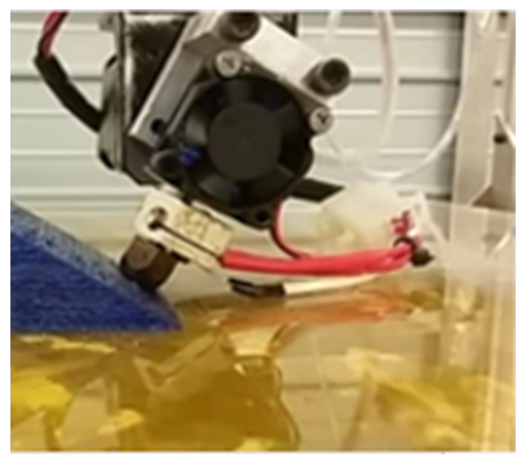
Crossply Laminate Manufacture with a Single Continuous Tow

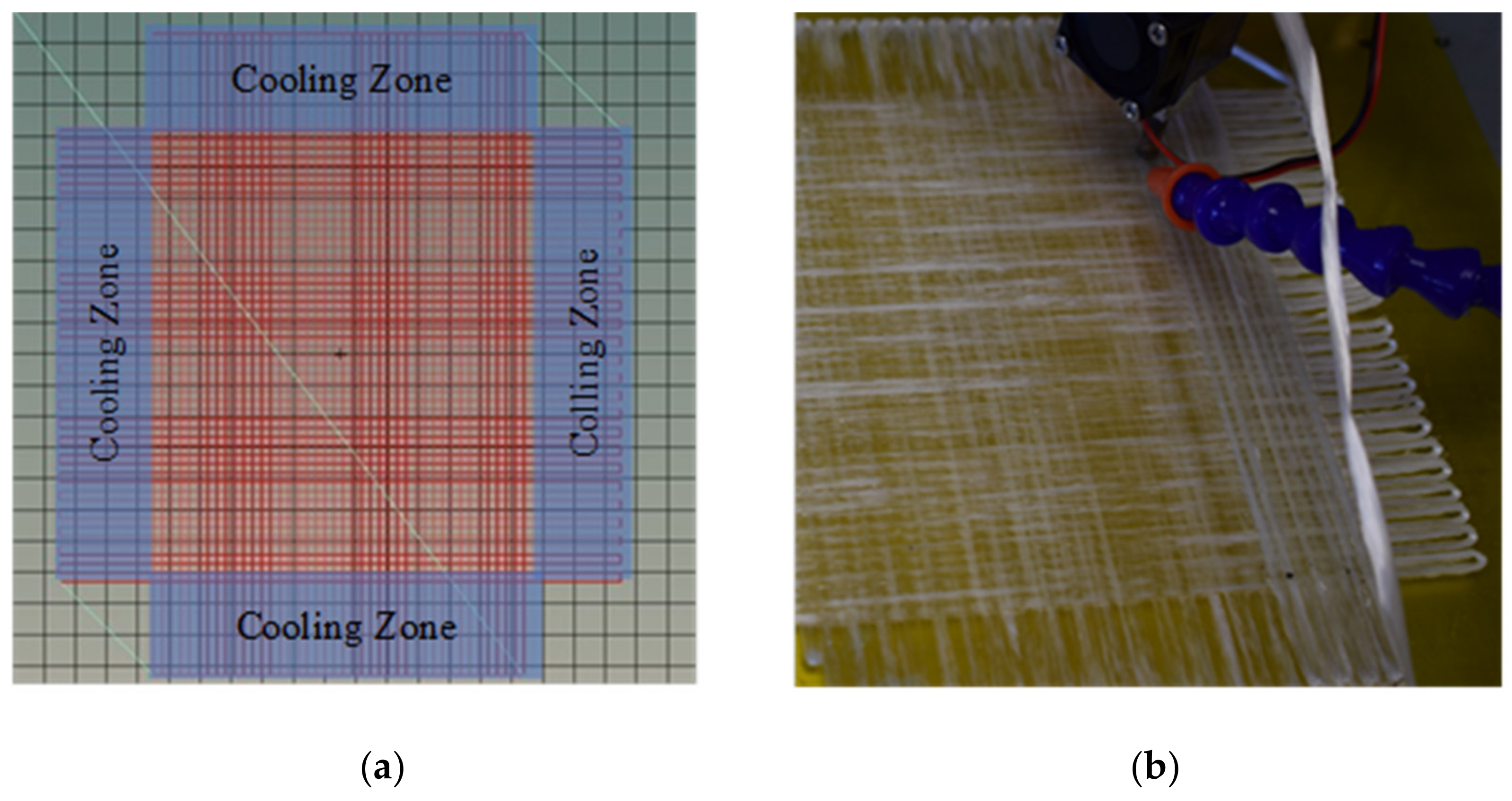
Due to the loss of consistent consolidation pressure on sloped surfaces related to inadequate stiffness of the Z-axis, experiments investigating large deviations from linear placement paths were shifted to the horizontal plane. To demonstrate the effectiveness of using programmed localized tow cooling to enable a reduced tacked length and improve positional fidelity, five (5) composite laminates were created, each from a single continuous tow of commingled material through tight, 180°, turns at the edges of the laminate. The composite placement head with the extended reach, small diameter nozzle, is heated to a temperature of 290 °C and then moved at 180 mm/min across the substrate placing the commingled tow. These process conditions were determined based on a previous study of the effect of nozzle temperature versus print speed on the void content of beams produced from the same glass fiber/PETG commingled tow [18]. Once the placement head moves into the cooling zone, just off the edge of the laminate area, as shown in Figure 14a, the pressurized air turns on, cooling the tow for the 180° turn. The cooling reduces the distance required to generate the necessary shear strength. Once the turn is complete, the cooling air is switched off and the placement head moves in the opposite direction, repeating the process at each edge on the laminate until a layer is complete. The ability to implement this 180° turn indicates the effectiveness of the cooling control in improving the placement fidelity during direction transitions. When a single high-volume fraction continuous fiber reinforced layer is complete the composite placement head starts placing the next layer in a similar fashion, but with a different fiber orientation. During the placement of the subsequent layers, the commingled tows are being placed directly onto the previous continuous fiber reinforced/PETG layer. The thermoplastic adheres to the previous layer quickly and the bond is strong enough to withstand the friction force within the nozzle enabling the tow to double back on itself, at the end of each pass, utilizing the programmed cooling control. The resulting laminate shown in Figure 14b has a stacking sequence of [0/90/0]T. The yellow color of the Kapton tape heat bed surface that shows through indicates good flow of the PETG and good consolidation of the composite where the cooling flow is turned off, while the tow in the 180° turns remains opaque indicating poor wetout, consistent with the reduced nozzle temperature. This demonstrates the effectiveness of a local cooling control which allows high temperatures and consolidation pressures when switched off, yet good tow directional fidelity when activated.
To confirm the quality of the laminate produced, with the cooling flow off, the void fractions of five representative regions of each of the five (5) laminates were measured using a combination of ASTM D792 and ASTM D3171 [19,20]. The measured void contents are given in Table 2. With the exception of the [0/90/90/0] 4-ply laminate, all void fractions were below 3.5%.
These void fraction results suggest that the automated cooling control is effective in enabling a combination of both complex path control and good consolidation.
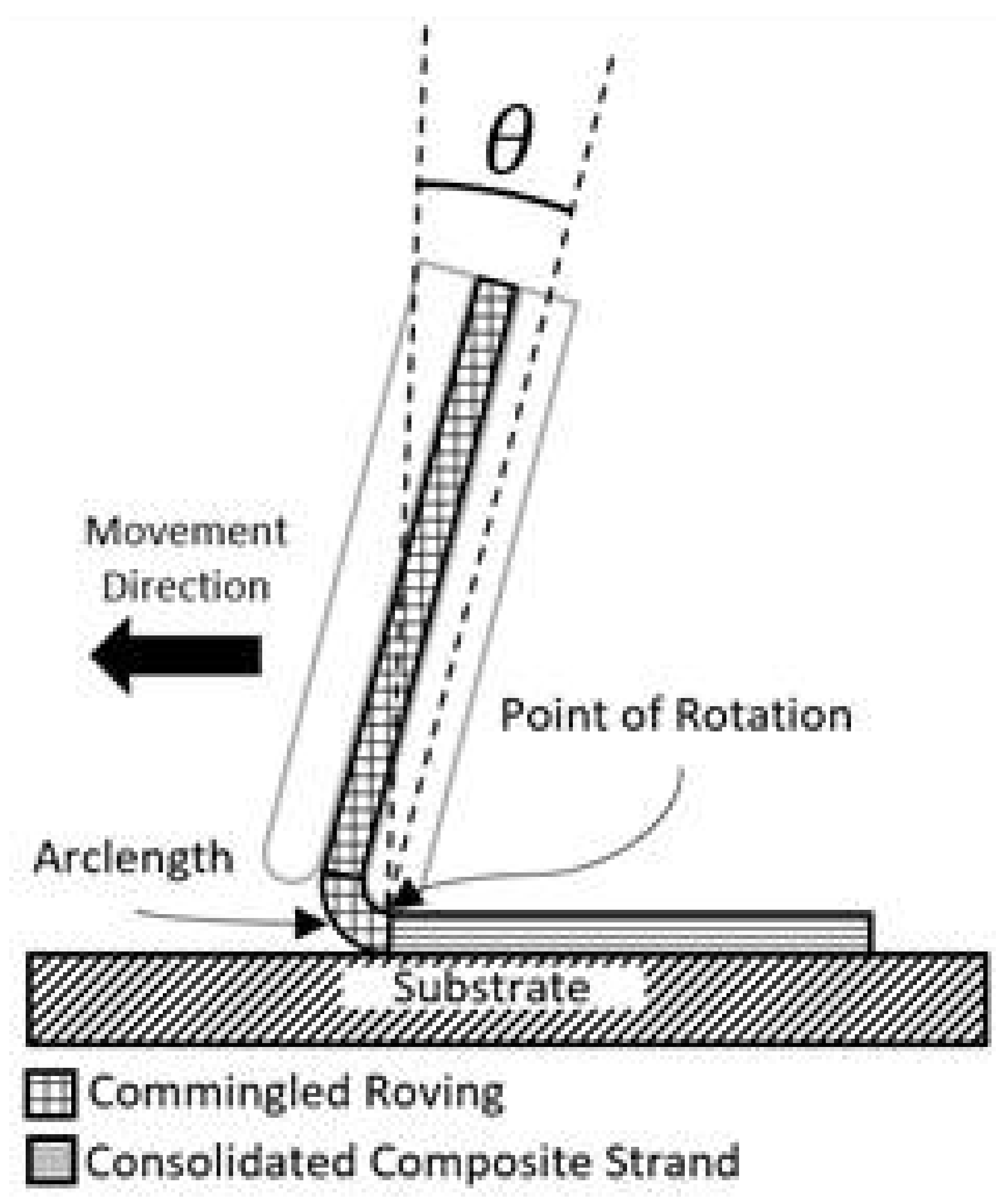
4.4. Tow Spreading

The final experiment undertaken investigated tow spreading, which varied the placement head nozzle angle with respect to the horizontal surface and measured the effect on tow width and geometry. Nozzle temperature was maintained at 260 °C. The maximum thickness, middle thickness, and tow width were measured at five points along the length of each placed tow, as shown in Figure 15.
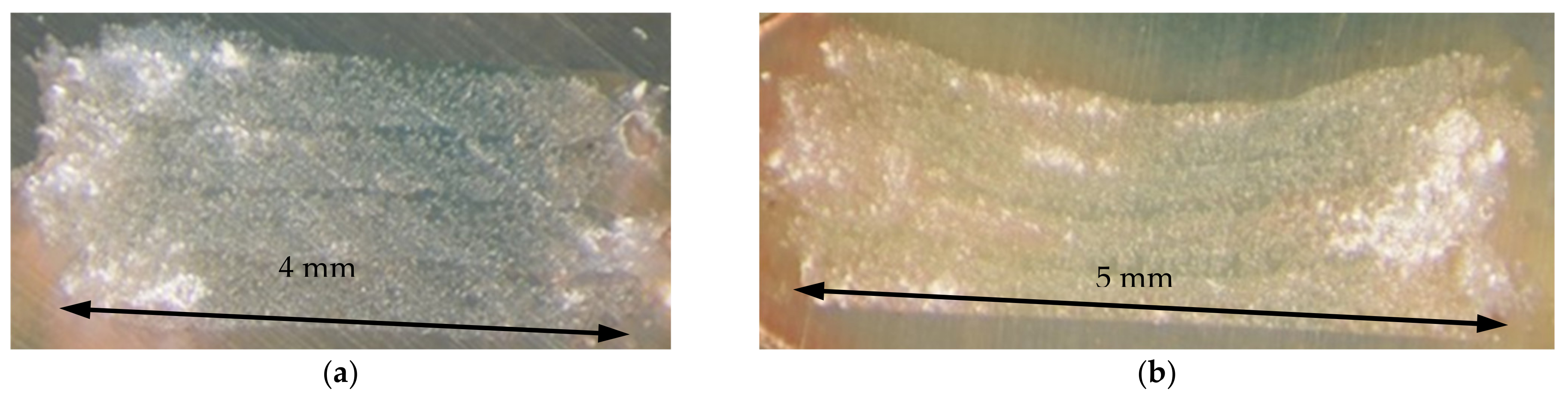
The conventional consolidation approach used throughout this study positions the nozzle perpendicular to the tool surface, which corresponds to a 0° nozzle inclination angle. This results in a consolidated tow with a flat surface as shown in Figure 16a. The concave shape created by the inclined nozzle can be seen, for the 25° nozzle inclination angle, in Figure 16b. Each layer has a thickness within the center of the consolidated tow that expands toward the edges of the sample. The measurements were made on sets of four tows placed one on top of another to improve the ability to measure the thickness changes, as shown in the micrographs of Figure 16, for 0° and 25° placement nozzle angles. Consolidation was accomplished by setting the layer height at 0.4 mm but utilizing an initial Z-offset of 0.2 mm. This forces the Z-motor to press the tip of the nozzle, and the first tow, against the stiff tooling plate, facilitating consolidation. Multiple cross-sections of each specimen were checked for quality and all were consistent with the results of Table 2 and with previous testing of unidirectional beams [18].
The results, shown in Figure 17, are tow dimensions plotted against the angle of the placement nozzle. The effect of nozzle angle on the tow width is clear, with the results showing an increase in tow width of just less than 50% at a nozzle angle of 30°, compared to the initial case of the nozzle perpendicular to the surface. The thickness decreases a similar percentage with the middle tow thickness most affected. The middle thickness decreased as the angle increased due to the shape of the nozzle, consolidation force, and the distance the fibers traveled along the surface of the nozzle. The standard deviation for the sets of five values is small, with the highest standard deviation, approximately 3%, being the measured for the widths produced in the 30° nozzle inclination angle sample.
Potentially more important than the maximum magnitude of tow spreading is the result that the effect is relatively linear with the nozzle angle change. This suggests that feedback control of the nozzle angle, based on tow width monitoring, may be an effective method for maintaining a uniform tow width, independent of placement path complexities.
Combining the results of the three experiments, it becomes clear that a multi-axis tow placement system is necessary to produce high-volume fraction continuous fiber reinforced composites on tools of changing face angle. This enables the nozzle to be maintained perpendicular to the changing tool surface. However, in addition to the implementation of multiple axes of control to position the placement nozzle, other features are necessary to enable high fidelity complex fiber path positioning. The incorporation of an automated, localized cooling system is shown to allow local tow tacking and thus, the ability to more immediately deviate from a linear path, executing tighter radius turns than otherwise possible. The effectiveness was demonstrated by 180° turns in the horizontal plane.
It was also recognized, during changes in direction, that the placed tow geometry changes. While this effect is complicated by the interrelations of consolidation pressure, the shear strength of the tacked tow, and limitations related to tow shearing, a separate method to modify tow width in real time was demonstrated through the use of the five-axis system to control the nozzle inclination angle.

5. Conclusions

Through the implementation of a five-axis commingled tow placement system it was demonstrated that maintaining the nozzle perpendicular to the tool surface resulted in similar consolidation on both the 30° sloped surface and the horizontal surface. However, due to a lack of stiffness in the Z-axis, the system failed to provide adequate consolidation on the 45° sloped tool surface. Increasing the stiffness of the Z-axis components would increase the ability to apply consolidation pressure and decrease deflections caused by the forces involved in the pultrusion of commingled materials. Through the addition of programmed local cooling and a redesigned nozzle, the tow tacking distance was reduced enabling improved path fidelity including tight, 180° turns while maintaining good consolidation, as demonstrated by void contents below 3.5% in all but one case. Finally, utilizing the capability of the five-axis system to vary the nozzle inclination angle and adjust the tow width, an increase approaching 50% in tow width over the perpendicular nozzle position was achieved. Thus, continued development, including nozzle inclination angle control for tow width modulation, has the potential to enable complex, high fidelity tow paths to be generated over complex tool surfaces while maintaining constant tow width.

Author Contributions

M.E.B. and D.W.R. were involved in Conceptualization, Methodology, Writing original draft; M.E.B. was involved in Investigation, Formal analysis; D.W.R. was involved in Writing review and editing, Project administration, Funding Acquisition. All authors have read and agreed to the published version of the manuscript.

Funding

This research was funded by the STATE OF COLORADO, ADVANCED INDUSTRY ACCELERATOR GRANT PROGRAM, grant number APP-112255.

Conflicts of Interest

The authors declare no conflict of interest.

References

  1. Prub, H.; Vietor, T. Design for Fiber-Reinforced Additive Manufacturing. J. Mech. Des. 2015, 137, 111409. [Google Scholar]
  2. Tekinalp, H.L.; Kunc, V.; Velez-Garcia, G.M.; Duty, C.E.; Love, L.J.; Naskar, A.K.; Blue, C.A.; Ozcan, S. Highly oriented carbon fiber–polymer composites via additive manufacturing. Compos. Sci. Technol. 2014, 105, 144–150. [Google Scholar] [CrossRef] [Green Version]
  3. Bettini, P.; Alitta, G.; Sala, G.; Di Landro, L. Fused Deposition Technique for Continuous Fiber Reinforced Thermoplastic. J. Mater. Eng. Perform. 2017, 26, 843–848. [Google Scholar] [CrossRef]
  4. Invernizzi, M.; Natale, G.; Levi, M.; Turri, S.; Griffini, G. UV-Assisted 3D Printing of Glass and Carbon Fiber-Reinforced Dual-Cure Polymer Composites. Materials 2016, 9, 583. [Google Scholar] [CrossRef] [PubMed] [Green Version]
  5. Eichenhofer, M.; Wong, J.C.; Ermanni, P. Continuous lattice fabrication of ultra-lightweight composite structures. Addit. Manuf. 2017, 18, 48–57. [Google Scholar] [CrossRef]
  6. Warlick, K.M. The Effect of Tow Shearing on Reinforcement Positional Fidelity in the Manufacturing of a Continuous Fiber Reinforced Thermoplastic Matrix Composite Via Pultrusion-like Processing of Commingled Feedstock. Master’s Thesis, Colorado State University, Fort Collins, CO, USA, 2017. [Google Scholar]
  7. Radford, D.W.; Hedin, K.M. Fused Deposition Technology Applied to Thermoplastic Matrix Placement and Wetout in Filament Winding. In Proceedings of the 20th International Conference on Composite Materials, Copenhagen, Denmark, 19–24 July 2015. [Google Scholar]
  8. Rodriguez, P.A.; Radford, D.W. Effect of Applied Consolidation Pressure in Direct Digital Manufacture of Continuous Fiber Reinforced Composites. In Proceedings of the CAMX Conference Proceedings, Orlando, FL, USA, 12–14 December 2017. [Google Scholar]
  9. Bourgeois, M.E. Toolless Out of Build Plane Manufacturing of Intricate Continuous Fiber Reinforced Thermoplastic Composites with a 3D Printing System. Master’s Thesis, Colorado State University, Fort Collins, CO, USA, 2019. [Google Scholar]
  10. Glycol-Modified Polyethylene Terephthalate. 20 September 2018. Available online: https://www.makeitfrom.com/material-properties/Glycol-Modified-Polyethylene-Terephthalate-PETG-PET-G (accessed on 1 June 2019).
  11. ASoM, AZO Materials E-Glass Fiber. 30 August 2001. Available online: https://www.azom.com/article.aspx?ArticleID=764 (accessed on 1 June 2019).
  12. Warlick, K.M.; Radford, D.W. Tow Positional Fidelity in a Continuous Fiber/3D Printing Approach on a Curved Surface. In Proceedings of the CAMX 2017, Orlando, FL, USA, 13 December 2017. [Google Scholar]
  13. Rodriguez, P.A.; Bourgeois, M.E.; Radford, D.W. Direct Manufacture of Continuous Fiber Reinforced Composites through a Combination of Fiber Placement and 3D Printing. In Proceedings of the CAMX Conference Proceedings, Anaheim, CA, USA, 27–29 September 2016. [Google Scholar]
  14. El-Dessouky, H.; Lawrence, C.; McGrail, T.; Broughton, B. Ultra-Light Weight Thermoplastic Composites: Tow-Spreading Technology. In Proceedings of the European Conference on Composite Materials, Venice, Italy, 24–28 June 2012. [Google Scholar]
  15. El-Dessouky, H.; Lawrence, C. Ultra-lightweight carbon fiber/thermoplastic composite material using spread tow technology. Compos. Part B 2013, 50, 91–97. [Google Scholar] [CrossRef]
  16. Harukazu, U. JEC Composites. May 2005. Available online: http://www.jeccomposites.com/print/knowledge/international-composites-news/innovative-technology-carbon-and-aramid (accessed on 1 June 2019).
  17. Rodriguez, P.A.; Radford, D.W. A Dynamic Mechanical Analysis Approach to Quality Evaluation of Additively Manufactured Continuous Fiber Reinforced Thermoplastics. In Proceedings of the CAMX 2019, Anaheim, CA, USA, 24 September 2019. [Google Scholar]
  18. Rodriguez, P.A. Dynamic Mechanical Analysis for Quality Evaluation of Additively Manufactured Continuous Fiber Reinforced Thermoplastic Matrix Composites subject to Manufacturing Defects. Master’s Thesis, Colorado State University, Fort Collins, CO, USA, 2019. [Google Scholar]
  19. ASTM D792-20. Standard Test Methods for Density and Specific Gravity (Relative Density) of Plastics by Displacement; ASTM International: West Conshohocken, PA, USA, 2020; Available online: www.astm.org (accessed on 29 December 2020).
  20. ASTM D3171-15. Standard Test Methods for Constituent Content of Composite Materials; ASTM International: West Conshohocken, PA, USA, 2015; Available online: www.astm.org (accessed on 29 December 2020).
Figure 1. Schematic of the five-axis composite placement system.
Jcs 05 00073 g001
Figure 2. (a) Five-axis system; (b) W-axis armature; (c) max placement angle of W-axis.
Jcs 05 00073 g002
Figure 3. Forces involved in fiber extrusion.
Jcs 05 00073 g003
Figure 4. 30° trapezoid tool geometry.
Jcs 05 00073 g004
Figure 5. Nozzle designs for the composite placement head. (a) Original composite nozzle design; (b) improved composite nozzle design.
Jcs 05 00073 g005
Figure 6. An L bracket produced (a) without local air cooling and (b) with local air cooling, demonstrating the effectiveness of the cooling manifold. [12]
Jcs 05 00073 g006
Figure 7. Composite placement system anatomy.
Jcs 05 00073 g007
Figure 8. Nozzle/composite tow friction force testing setup.
Jcs 05 00073 g008
Figure 9. Tow spreading schematic.
Jcs 05 00073 g009
Figure 10. Nozzle rotation for tow placement/consolidation on a 30° angled tool face.
Jcs 05 00073 g010
Figure 11. (a) Non-linear, (b) linear paths on 30°, and (c) 45° trapezoidal tool sloped surfaces.
Jcs 05 00073 g011
Figure 12. Non-linear placement path.
Jcs 05 00073 g012
Figure 13. Nozzle/composite friction force of pulling the composite tow through the nozzle.
Jcs 05 00073 g013
Figure 14. Manufacturing of a continuous fiber laminate; (a) G-code with cooling zones and (b) the manufactured laminate.
Jcs 05 00073 g014
Figure 15. Resulting tow cross-section schematic.
Jcs 05 00073 g015
Figure 16. Cross-sections of (a) 0° and (b) 25° nozzle inclination angle specimens.
Jcs 05 00073 g016
Figure 17. Change in thickness and width with Nozzle Inclination Angle.
Jcs 05 00073 g017
Table 1. Commingled roving constituent material properties.
PropertyAmorphous PETG [10]Glass Fiber [11]
Elastic Modulus2.83 GPa72.4 GPa
Flexural Modulus1.98 GPa30.0 GPa
Density1.27 g/cm32.55 g/cm3
Table 2. Void fractions of continuous fiber laminates.
Laminate Stacking SequenceNumber of PliesAverage Void Fraction (%)Void Fraction Standard Deviation (%)
[0]13.11.6
[0/90]22.10.5
[0/90/0]31.91.1
[0/90/90/0]47.02.0
[0/90/0/90/0]53.41.4
Publisher’s Note: MDPI stays neutral with regard to jurisdictional claims in published maps and institutional affiliations.

