Article

Using Graphene Nanoplatelets Nanofluid in a Closed-Loop Evacuated Tube Solar Collector—Energy and Exergy Analysis

1
Center of Advanced Materials, Department of Mechanical Engineering, Faculty of Engineering, University of Malaya, Kuala Lumpur 50603, Malaysia
2
School of Mechanical Engineering, The University of Adelaide, Adelaide, SA 5005, Australia
3
Department of Chemical Engineering, Faculty of Engineering, University of Malaya, Kuala Lumpur 50603, Malaysia
4
Faculty of Engineering and Information Technology, University of Technology Sydney, Sydney, NSW 2007, Australia
*
Authors to whom correspondence should be addressed.
J. Compos. Sci. 2021, 5(10), 277; https://doi.org/10.3390/jcs5100277
Submission received: 13 August 2021 / Revised: 16 September 2021 / Accepted: 8 October 2021 / Published: 15 October 2021

Abstract

:
Recently, nanofluid application as a heat transfer fluid for a closed-loop solar heat collector is receiving great attention among the scientific community due to better performance. The performance of solar systems can be assessed effectively with the exergy method. The present study deals with the thermodynamic performance of the second law analysis using graphene nanoplatelets nanofluids. Second law analysis is the main tool for explaining the exergy output of thermodynamic and energy systems. The performance of the closed-loop system in terms of energy and exergy was determined by analyzing the outcome of field tests in tropical weather conditions. Moreover, three parameters of entropy generation, pumping power and Bejan number were also determined. The flowrates of 0.5, 1 and 1.5 L/min and GNP mass percentage of 0.025, 0.5, 0.075 and 0.1 wt% were used for these tests. The results showed that in a flow rate of 1.5 L/min and a concentration of 0.1 wt%, exergy and thermal efficiencies were increased to about 85.5 and 90.7%, respectively. It also found that entropy generation reduced when increasing the nanofluid concentration. The Bejan number surges up when increasing the concentration, while this number decreases with the enhancement of the volumetric flow rate. The pumping power of the nanofluid-operated system for a 0.1 wt% particle concentration at 0.5 L/min indicated 5.8% more than when pure water was used as the heat transfer fluid. Finally, this investigation reveals the perfect conditions that operate closest to the reversible limit and helps the system make the best improvement.

1. Introduction

Nowadays, different types of solar systems can provide energy for many high-energy demand applications [1]. Various solar collectors have been available, but low energy conversion efficiency is the main reason for further investigations [2]. Water as a conventional fluid is commonly applied in heat transfer applications, but it has low thermophysical properties and heat transfer coefficient. A researcher found that this liquid’s thermal properties and heat capacity will improve by immersing nanoparticles into the water. This solution has received lots of attention from researchers [3,4,5,6,7]. Consequently, several parameters have had an impact on the performance of nanofluids, such as their stability, agglomeration, viscosity, interfacial nanomaterial layering, Brownian motion and nanomaterial size [8]. According to many findings, in the “Nano-age”, there will be an extensive revolution in many industrialized processes such as water treatment, agriculture and solar heating–cooling systems [9].
The nanofluid’s most significant benefit is that it is superior operating in characterizations such as a thermal energy storage capacity, friction reduction and heat transfer coefficients [10,11]. Graphene is used in various forms, such as a single-atom-thick sheet of hexagonally arranged, multi-layer graphene (MLG), graphene quantum dots (GQD), graphene oxide (GO), reduced graphene oxide (rGO) and graphene nanoplatelets (GNP) [12,13,14,15]. Graphene provides several advantages in the case of using nanoparticles. Within the past decade, it was studied widely. Graphene is easy to synthesize, has a longer suspension time and larger surface (1000 times larger than other nanoparticles), with higher carrier mobility, high stability, low erosion and corrosion and high thermal conductivity [16]. Graphene-based nanofluids have found applications such as heat transfer, biomedical and cosmetics [17]. Borode et al. [18] reviewed several research papers published before 2019 and summarized that carbon-based low concentration nanofluids—under specified conditions—improved the efficiency of different types of solar heat collectors.
Mansour [19] concluded that an evacuated tube solar collector (ETSC) has better energetic and exegetic efficiencies in comparison with a flat plate solar collector (FPSC). Al-Tahaineh and Damseh [20] have worked on an ETSC with a single-ended direct flow. According to the outcomes, the exergetic efficiency is directly proportional to the fluid’s inlet/outlet temperature difference. Generally, at higher temperature differences, the ETSC shows good exergetic efficiencies [21,22]. Pandey [23] conducted an experiment test on an ETSC-based solar air heater and found that the average energy and exergy efficiencies will improve by 66.57 and 13.38%, respectively.
Exergy and entropy generation analysis is a crucial parameter through thermodynamic transformations for explaining a system’s irreversibility influence [24]. The exergy analysis is required to appropriately design the energy transformation processes of changing quality levels [25]. In recent years, exergy analysis has become an effective technique to optimize thermodynamic systems led toward sustainable development and maximizing energy saving [26]. The inner losses cannot be identified by the first law of thermodynamics to calculate the heat transfer efficiency. According to the second law of thermodynamics, the exergy analysis of a system and sources of thermodynamic imperfection can be estimated [27]. Recently, the exergy concept has drawn considerable attention in the thermodynamic examination of thermal processes [28,29]. The entropy generation minimization method is one of the powerful tools to optimize the thermal management system’s performance and find the solution to deduct the lost work in a process [30]. The entropy generation rate (irreversibility) analysis measures entropy created by irreversibility corresponding to thermal and frictional loss [31].
Alous et al. [32] investigated the energetic and exergy analysis of a photovoltaic thermal collector (PVT) when using graphene nanoplatelets and multi-walled carbon nanotubes (MWCNT) with the base of water. Tests indicated that adding the thermal unit to the photovoltaic (PV) module helps to enhance the total energetic efficiency (exergy efficiency) by 53.4% (11.2%) for distilled water, 57.2% (12.1%) for MWCNT-water and 63.1% (20.6%) for graphene-water. Alawi et al. [33] tested the effects of using a water-based nanofluid with the presence of Pentaethylene Glycol-Treated Graphene Nanoplatelets on the thermal performance of an FPSC. Tests were carried out with different concentrations, inlet temperature, flow rates and flux intensity. They found that using this new nanofluid helps to increase the FPSC efficiency by up to 13.3% for these nanofluids.
Bahiraei et al. [34] studied the exergy of a novel rotary coaxial cross double-twisted tape (RCCDTT) when using an eco-friendly graphene-based nanofluid. Active and passive heat transfer enhancement methods were examined at the same time. With a higher concentration, the irreversibility is reduced, and the least exergy destruction rate is about 24%. Yarmand et al. [35] studied several parameters of a functionalized graphene nanoplatelets (f-GNP) nanofluids. A square pipe with a constant input heat flux was chosen for this test. They found that thermal enhancement is proportional to the temperature and weight concentration of nanoparticles. Sarafraz and Safaie [36] filled a heat pipe in an ETSC with a graphene–methanol nanofluid. The tilt angle of the collector, filling ration and the mass fraction of the nanofluid are some of the studied parameters. The nanofluid increases the thermal efficiency by 19% at 0.1% wt.
This research began with the optimization of the thermal conductivity and viscosity of GNP nanofluids by using Design of Expert (DOE) [8]. Three influential parameters including the concentration, temperature and specific surface area of graphene nanosheets were investigated, which are the effective parameters on the viscosity and thermal conductivity of aqueous graphene nanosheets (GNP) nanofluids. We follow our research by applying this nanofluid on the evacuated tube solar collector (ETSC) to investigate the thermal efficiency enhancement [37]. The thermal efficiency tests on the solar collector were carried out for varying volumetric flow rates of 0.5, 0.1 and 1.5 L/min, while the ASHRAE standard 93-2003 was considered to calculate the efficiency of the collector. In this study, we focus on evaluating the expanded energy collection, exergy, entropy generation and pumping power performance of the evacuated heat pipe solar collector based on our previous research under given operating conditions for thermal performance assessment under actual field conditions in a tropical region of Malaysia.

2. Analytical Methodology

Three mathematical equations are employed to determine the energy, exergy, pumping power and entropy generation.

2.1. Energy Efficiency

The heat transfer ( Q . u ) to the nanofluid is determined from the following equation:
Q . u = m . c p ( T . o u t T . i n )
where c p is specific heat capacity, T . i n is inlet temperature, T . o u t is outlet temperature and m . is the mass flow rate.
The solar energy absorption by collector ( Q . i n ) as input energy is calculated from the following equation:
Q . i n = A C S .
where A C is the solar energy collection area of ETSC and S . presents the solar radiation.
The total energy efficiency of the system (η) is determined by dividing the heat transfer to nanofluid and energy input as follows [38]:
η = Q u Q i n

2.2. Exergy Efficiency

The exergy has different behavior depending on the operation condition. It can be determined by using the first and second thermodynamic laws. There are a few assumptions in this experiment.
  • The potential energy is negligible.
  • The kinetic energy is negligible.
  • The thermophysical properties of the nanofluids are constant.
  • The work transfer from the system is a positive value.
  • The flow rate is steady.
  • The system is in steady-state conditions.
Therefore, the exergy balance of the system is expressed as follows:
E . i n E . o u t = E . d e s t
where ( E . i n )   and   ( E . o u t ) are the exergy input and output, respectively, and ( E . d e s t ) is the destruction rate. Δ E . is the exergy rate and can be defined as follows:
Δ E . = m . b f [ ( h . o u t h . i n ) T . a ( s . o u t s . i n ) ]
The specific enthalpy of the fluid at the outlet and inlet are h . i n and h . o u t (J/kg). The entropy generation of the nanofluid at outlet and inlet are s . i n and s . o u t (J/kg·K), respectively. The ambient temperature is T . a (K). Moreover, it is equal to 300 K in this study.
The changes in the entropy and enthalpy of the solar collector are expressed as follows:
Δ h . = h . o u t h . i n = c p , n f ( T . f , o u t T . f , i n )
Δ s . = s . o u t s . i n = c p , n f l n T . f , o u t T . f , i n R f l n P . o u t P . i n
Equations (5)–(7) can be established as follows:
E . d e s t = m . b f [ c p , n f ( T . f , o u t T . f , i n ) T . a ( c p , n f l n T . f , o u t T . f , i n R f l n P . o u t P . i n ) ]
Equation (8) is reordered due to P i n and P o u t pressures being equal as follows:
E . d e s t = m . f c p , n f [ ( T . f , o u t T . f , i n ) T . a l n T . f , o u t T . f , i n ]
The total rate of the exergy ( E . s ) received from the solar radiation is defined as follows:
E . s = S . A c ( 1 T a . T . s )
where Ta and Ts stand for ambient temperature and apparent sun temperature, respectively. The heat transfer process from the sun to the collector’s working fluid consists of two main parts, absorbing the solar radiation by the absorber plate and heat transfer from the absorber plate to the working fluid.
Therefore, the total exergy efficiency ( η e x ) is defined as follows:
η e x = 1 E . d e s t E . s

2.3. Pressure Drop

The pump carries out the circulation of nanofluid through the system. The pressure drop was estimated as follows [39]:
Δ P . = f ρ V . 2 2 Δ l d + K ρ V . 2 2
where K is the loss coefficient and regularly derived from tables estimated via formulas. The velocity ( V . ) is calculated as follows:
V . = m . ρ n f π D H 2 / 4    
The density of nanofluid ( ρ n f ) can be calculated as follows [40]:
ρ n f = φ ρ n p + ( 1 φ ) ρ b f
For assuming Reynolds number, the following relation can be used:
R e = ρ V D H μ

2.4. Pumping Power

The following relation can be used to estimate the pumping power ( P p u m p ) [41]:
p u m p i n g   p o w e r = ( m . ρ n f ) × Δ p

2.5. Entropy Generation

The entropy generation can be estimated through the following equation [42]:
S . g e n = η o G A C ( 1 T ˙ p 1 T ˙ s ) + m . c p , n f ( ln ( T ˙ o u t T ˙ i n ) ( T ˙ o u t T ˙ i n ) T p ) + U L A C ( 1 T ˙ a T ˙ p ) ( T ˙ p T ˙ a 1 ) S . g e n Δ T + m . Δ P ˙ ρ n f ln ( T ˙ o u t T ˙ a ) ( T ˙ o u t T ˙ i n ) S . g e n Δ P
where Δ P is the pressure drop (Pa), and A C is the surface area (m2) of the solar collector. Moreover, T . s is the apparent sun temperature, T . s is the mean temperature of the absorber plate, T . a is the ambient temperature, m . is the mass flow rate of nanofluid (L/min) and T . i n and T . o u t are the inlet and outlet temperatures of the working fluid, respectively.

2.6. Bejan Number

Bejan number can be described as follows [43]:
B e = S . g e n Δ T S . g e n Δ T + S . g e n Δ P

3. Experimental Procedures

3.1. Material

In this experimental investigation, GNP nanosheets powder (Grade C, XG Sciences, Inc., Lansing, MI, USA) with a carbon content of >99.5, an average diameter of 2 nm and a specific surface area of 750 m2/g was used. The granular form of graphene nanoplatelets is soluble in water. Therefore, distilled water was used as a base fluid.

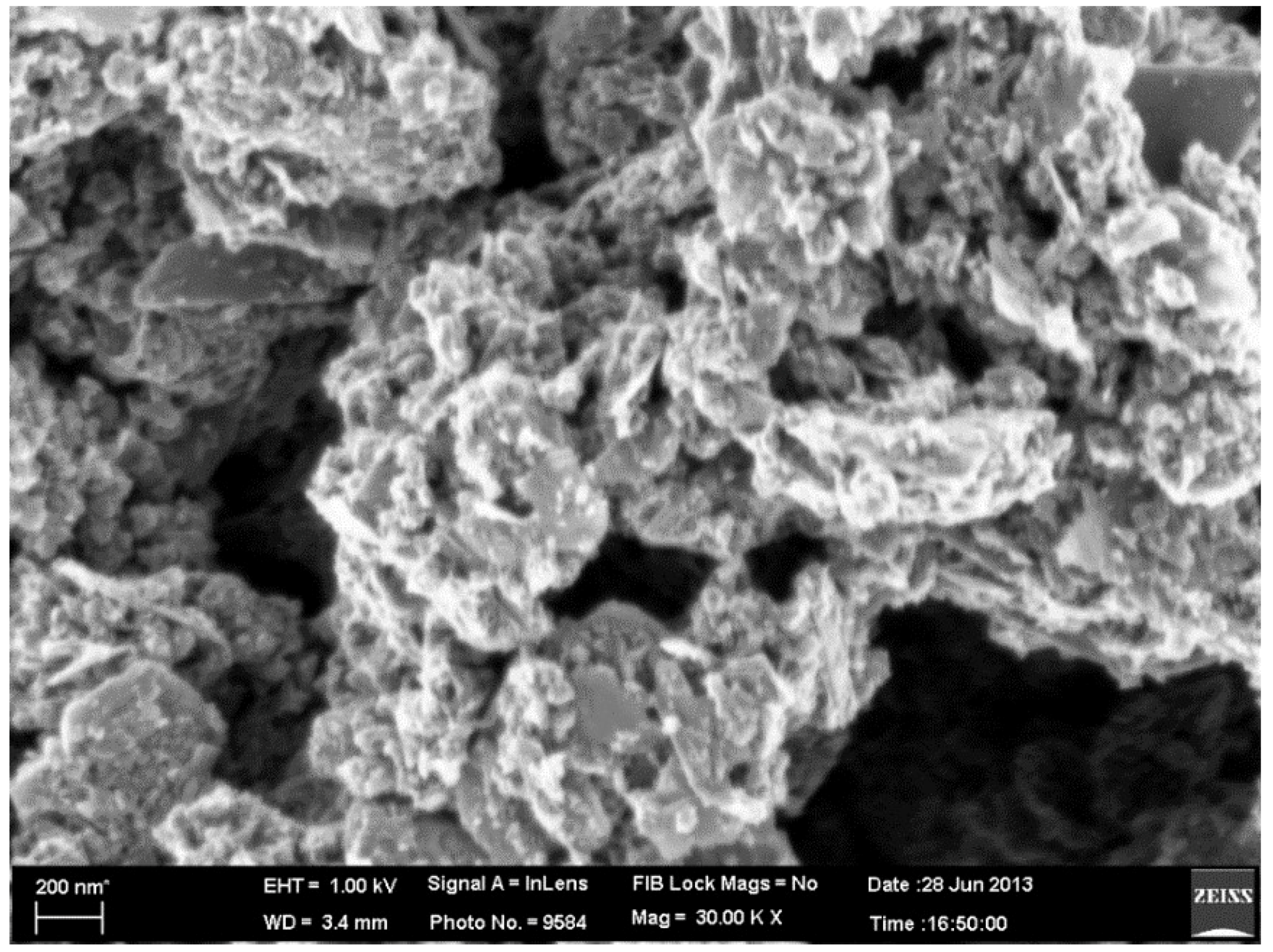
3.2. Nanofluid Preparation and Stability

One of the most important practical issues is the long-term stability of nanofluids. The aggregation of nanoparticles leads to non-homogeneous nanofluids due to robust Van der Waal’s interactions. Therefore, some physical and chemical techniques have been used to stabilize the nanofluids, such as using surfactants and impacting solid force on the cluster of the suspended particle. For reducing the sedimentation and aggregation of GNP suspended in distilled water (DW), an ultrasonication probe with a 20 kHz frequency power supply and 1200 W output power was employed to optimize the dispersion. Based on the stability tests, the nanofluids’ concentrations were stable after three months of initial preparation (see Figure 1).
This investigation further examined the detailed microstructure and morphological characterization of graphene nanoplatelets using the field emission scanning electron microscopy (FESEM) microscope. As it is shown in Figure 2, FESEM images prove that GNP nanosheets are in nano size.

3.3. Experimental Setup

The setup consists of an ETSC, pipes, pyranometer, anemometer, nanofluid tank, flowmeter, heat exchanger, pump, thermocouples, controller and cooling water tank (50 L). Four thermocouples (RTD PT-100) were prepared and placed on the system to measure temperatures at entry/exit of the water pipe in the manifold, inlet/outlet of the storage tank and surroundings. All thermocouples and other sensors were connected to a data logger. Table 1 contains details and dimensions of the ETSC. The experimental setup is shown in Figure 3. The performance of heat pipes mainly depends on their tilt from the horizon due to their gravitational specifications.
The tilt angle is fixed at 30° to maximize the heat pipe’s performance and solar energy absorption. The volumetric flow rates are set in three cases of 0.5, 1.0 and 1.5 L/min.

3.4. Testing Method

The calibration of all measuring instruments was confirmed before use. To establish a steady-state condition for setup and data collection, ASHRAE 93-2003 standard was used (see Table 2). Experimental data collection was carried out from early January until the end of September. Different types of weather conditions were considered in the test days. The data recording was from 9:30 am to 5:00 pm. The daily average recorded solar radiation (G) was 1134.784 W/m2.

3.5. Uncertainties in Measurements

All devices and sensors have a level of inaccuracy. The inaccuracy was generated from the thermocouples, pyranometer, anemometer, flow meter and pump. In this experiment, inaccuracy is 1% in pyranometer, 0.3% in pressure transducer at 25 ± 0.1 °C in RTD sensors, 2% inflow meter and 3% in anemometer.

4. Results and Discussion

To determine the optimum particle concentration and flow rate for maximizing solar collector thermal efficiency, several factors have been determined, which will be explained in this section.

4.1. Efficiencies

From the result, it can be observed that by increasing the flow rate and particle concentration, the thermal efficiency of the collector is enhanced as shown in Figure 4a. The collector has its maximum energy efficiency for each type of flow at the volumetric flow rate of 1.5 L/min. Figure 4a shows that the nanofluid with a 0.1 wt% concentration provides the highest range of energy efficiency, reaching over 90% in 1.5 L/min (36% higher than distilled water).
The inlet/outlet temperature difference of the fluid is reduced by increasing the flow rate. This causes a reduction in energy efficiency. Due to the high thermal conductivity of nanofluids, the concentration of GNP nanosheets directly proportions the temperature difference [37]. The maximum value was recorded at 23.6 °C for GNP nanofluid at 0.1 wt%. The main reason for improving the heat transfer properties is the stochastic motion of the GNP nanosheets. Generally, an enhancement of thermal conductivity causes the improvement of the convective heat transfer coefficient, and these two results increment in energy efficiency.
The result presented in Figure 4b shows how exergy efficiency enhances particle concentration and simultaneously decreases with flow rate. Based on the results, it is observed that the optimum exergy efficiency is 91%, which occurred in 0.1 wt% and 0.5 L/min volumetric flow rate. Referring to Equation (9), the interaction of flow rate and heat capacity significantly affect exergy efficiency.

4.2. Exergy Destruction and Entropy Generation

Based on the maximum second law efficiency, it is essential to estimate the exergy analysis of the system, which is related to the viscous friction loss and heat transfer parameters. It is obvious from Figure 5a that exergy destruction has a similar pattern to compare to entropy generation in Figure 5b. According to Equation (17), entropy generation plays the main role in analyzing the exergy destruction of the collector and is the primary tool for explaining the irreversible influence of a system. The maximization output power in the solar collector can be achieved by minimizing the entropy generation. Figure 5a shows that the exergy destruction decreased with nanofluid concentration enhancement, which can be explained by the viscosity, entropy generation and irreversibility. Additionally, the exergy destruction effect can be reduced with the flow rate enhancement, and entropy generation decreases.
The Bejan number has a substantial role in thermal systems, primarily where entropy generation occurs, related to internal irreversibility and fluid flow rates. It can be explained as the ratio of heat transfer irreversibility to total irreversibility due to heat transfer and fluid friction. Figure 6a displays the effect of different volumetric flow rates and particle concentrations on the Bejan number. It can be observed that the Bejan number enhances when increasing the particle concentration at a constant flow rate. It was found that total entropy generation increases by particle loading. A low particle concentration nanofluid (0.025 wt%) causes a weak Brownian interaction between the GNP nanosheets and the base fluid. This leads to the face similar behavior of the nanofluid and base fluid. Figure 6b illustrates the Bejan number variations at the different GNP nanofluid concentrations and flow rates. With an increase in the flow rate, the Bejan number drops dramatically. It indicates the effectiveness of a higher flow rate on the reduction in the contribution of heat transfer to total irreversibility.

4.3. Pumping Power

The increment of pumping power has an adverse effect on thermal and exergetic efficiency. Figure 7 shows that logically, the pumping power rises by increasing the flow rate and nanofluid concentration. However, this surge is not that imposing. In 1.5 L/min, the pump power increment is 1.1 and 5.8% for a 0.025 and 0.1 wt% particle concentration, respectively.

5. Conclusions

The performance of a closed-loop ETSC was experimentally studied when using GNP nanofluids instead of distilled water. The analysis was performed according to the second law of thermodynamics. The following conclusions could be drawn from the result of applying GNP nanofluids with different flow rates and particle concentrations in the collector:
  • The outcome reveals the significant enhancement in the thermal efficiency of the setup using GNP nanofluid by 35.8% for 0.1 wt% nanoparticle concentration and volumetric flow rate at 1.5 L/min.
  • The outcome reveals that by applying a GNP nanofluid in the setup, the exergetic efficiency was boosted about 20.5% in comparison with water under the same conditions.
  • Pumping power increases when the concentration increases or the flow rate rises, which is not preferable. However, its impact is less noticeable compared with the rise of thermal efficiency and exergy.
  • The entropy number decreases when increasing the nanofluid concentration and flow rate, which is desirable.
  • The Bejan number has been observed to rise by adding nanoparticles to the base fluid.
The findings pave the way for improving the thermal efficiency of solar collectors by replacing water with nanofluids. Although researchers have conducted many theoretical and experimental investigations, a specific obstacle needs to be solved for commercial heat transfer applications such as agglomeration, erosion, corrosion and instability. Scientists should explore the optimization of the interaction between nanoparticles and water and the effect of temperature on the operation of nanofluids in future research.

Author Contributions

Formal analysis, S.I. and A.E.; Methodology, A.E.; Supervision, M.S., B.C.A. and H.C.O.; Validation, M.S.N.; Writing—original draft, S.I.; Writing—review & editing, M.S. and M.S.N. All authors have read and agreed to the published version of the manuscript.

Funding

This research received no external funding.

Institutional Review Board Statement

Not applicable.

Informed Consent Statement

Not applicable.

Conflicts of Interest

The authors declare no conflict of interest.

Terminology

Aabsorbance area, m2
BeBejan number
Cpspecific heat, J/kg K
E . exergy, W
hspecific enthalpy, J/kg
kthermal conductivity, W/m K
mass flow rate, kg/s
Qenergy, W
ReReynolds number
Sreceived solar radiation to the plate, W/m2
entropy rate, W/K
Ttemperature, °C
wt%weight percentage
Subscripts
iinlet
ccollector
ooutlet
ininput
outoutput
uuseful
aambient
pnanoparticle
nfnanofluid
bfbase fluid
gengeneration
destdestruction
Greek symbols
ηefficiency (%)
Δdifference
ρdensity, kg/m3
φnanoparticle volume fraction, vol.%
μviscosity, mPa.s

References

  1. Bellos, E.; Tzivanidis, C.; Antonopoulos, K.; Gkinis, G. Thermal enhancement of solar parabolic trough collectors by using nanofluids and converging-diverging absorber tube. Renew. Energy 2016, 94, 213–222. [Google Scholar] [CrossRef]
  2. Kasaeian, A.; Eshghi, A.T.; Sameti, M. A review on the applications of nanofluids in solar energy systems. Renew. Sustain. Energy Rev. 2015, 43, 584–598. [Google Scholar] [CrossRef]
  3. Gangacharyulu, D. Preparation and Characterization of Nanofluids and Some Investigation in Biological Applications. Ph.D. Thesis, Thapar University, Patiala, India, 2010. [Google Scholar]
  4. Said, Z.; Sajid, M.; Saidur, R.; Kamalisarvestani, M.; Rahim, N. Radiative properties of nanofluids. Int. Commun. Heat Mass Transf. 2013, 46, 74–84. [Google Scholar] [CrossRef]
  5. Saidur, R.; Meng, T.; Said, Z.; Hasanuzzaman, M.; Kamyar, A. Evaluation of the effect of nanofluid-based absorbers on direct solar collector. Int. J. Heat Mass Transf. 2012, 55, 5899–5907. [Google Scholar] [CrossRef]
  6. Colangelo, G.; Favale, E.; de Risi, A.; Laforgia, D. A new solution for reduced sedimentation flat panel solar thermal collector using nanofluids. Appl. Energy 2013, 111, 80–93. [Google Scholar] [CrossRef]
  7. Otanicar, T.P.; Phelan, P.E.; Prasher, R.S.; Rosengarten, G.; Taylor, R.A. Nanofluid-based direct absorption solar collector. J. Renew. Sustain. Energy 2010, 2, 033102. [Google Scholar] [CrossRef] [Green Version]
  8. Iranmanesh, S.; Mehrali, M.; Sadeghinezhad, E.; Ang, B.C.; Ong, H.C.; Esmaeilzadeh, A. Evaluation of viscosity and thermal conductivity of graphene nanoplatelets nanofluids through a combined experimental–statistical approach using respond surface methodology method. Int. Commun. Heat Mass Transf. 2016, 79, 74–80. [Google Scholar] [CrossRef]
  9. Bait, O.; Si-Ameur, M. Enhanced heat and mass transfer in solar stills using nanofluids: A review. Sol. Energy 2018, 170, 694–722. [Google Scholar] [CrossRef]
  10. Sadeghinezhad, E.; Mehrali, M.; Rosen, M.A.; Akhiani, A.R.; Latibari, S.T.; Mehrali, M.; Metselaar, H.S.C. Experimental investigation of the effect of graphene nanofluids on heat pipe thermal performance. Appl. Therm. Eng. 2016, 100, 775–787. [Google Scholar] [CrossRef] [Green Version]
  11. Esmaeilzadeh, A.; Silakhori, M.; Nik Ghazali, N.N.; Metselaar, H.S.C.; Bin Mamat, A.; Naghavi Sanjani, M.S.; Iranmanesh, S. Thermal Performance and Numerical Simulation of the 1-Pyrene Carboxylic-Acid Functionalized Graphene Nanofluids in a Sintered Wick Heat Pipe. Energies 2020, 13, 6542. [Google Scholar] [CrossRef]
  12. Bahiraei, M.; Heshmatian, S. Graphene family nanofluids: A critical review and future research directions. Energy Convers. Manag. 2019, 196, 1222–1256. [Google Scholar] [CrossRef]
  13. Khosravi, R.; Rabiei, S.; Khaki, M.; Safaei, M.R.; Goodarzi, M. Entropy generation of graphene–platinum hybrid nanofluid flow through a wavy cylindrical microchannel solar receiver by using neural networks. J. Therm. Anal. Calorim. 2021, 145, 1949–1967. [Google Scholar] [CrossRef]
  14. Sarafraz, M.M.; Tlili, I.; Tian, Z.; Bakouri, M.; Safaei, M.R.; Goodarzi, M. Thermal Evaluation of Graphene Nanoplatelets Nanofluid in a Fast-Responding HP with the Potential Use in Solar Systems in Smart Cities. Appl. Sci. 2019, 9, 2101. [Google Scholar] [CrossRef] [Green Version]
  15. Goodarzi, M.; Kherbeet, A.S.; Afrand, M.; Sadeghinezhad, E.; Mehrali, M.; Zahedi, P.; Wongwises, S.; Dahari, M. Investigation of heat transfer performance and friction factor of a counter-flow double-pipe heat exchanger using nitrogen-doped, graphene-based nanofluids. Int. Commun. Heat Mass Transf. 2016, 76, 16–23. [Google Scholar] [CrossRef]
  16. Arshad, A.; Jabbal, M.; Yan, Y.; Reay, D. A review on graphene based nanofluids: Preparation, characterization and applications. J. Mol. Liq. 2019, 279, 444–484. [Google Scholar] [CrossRef]
  17. Sadeghinezhad, E.; Mehrali, M.; Saidur, R.; Mehrali, M.; Latibari, S.T.; Akhiani, A.R.; Metselaar, H.S.C. A comprehensive review on graphene nanofluids: Recent research, development and applications. Energy Convers. Manag. 2016, 111, 466–487. [Google Scholar] [CrossRef]
  18. Borode, A.; Ahmed, N.; Olubambi, P. A review of solar collectors using carbon-based nanofluids. J. Clean. Prod. 2019, 241, 118311. [Google Scholar] [CrossRef]
  19. Mansour, M.K. Thermal analysis of novel minichannel-based solar flat-plate collector. Energy 2013, 60, 333–343. [Google Scholar] [CrossRef]
  20. Al-Tahaineh, H.; Damseh, R. Exergy Analysis of A Single-Ended Glass Direct Flow Evacuated Tube Solar Collector. Int. J. Adv. Res. Eng. Technol. (IJARET) 2013, 4, 1–9. [Google Scholar]
  21. Ismail, K.; Abogderah, M. Performance of a heat pipe solar collector. J. Sol. Energy Eng. 1998, 120, 51–59. [Google Scholar] [CrossRef]
  22. Liu, Z.-H.; Hu, R.-L.; Lu, L.; Zhao, F.; Xiao, H.-S. Thermal performance of an open thermosyphon using nanofluid for evacuated tubular high temperature air solar collector. Energy Convers. Manag. 2013, 73, 135–143. [Google Scholar] [CrossRef]
  23. Pandey, A.K. Exergy Analysis and Exergoeconomic Evaluation of Renewable Energy Conversion Systems. 2014. Available online: http://hdl.handle.net/10603/16319 (accessed on 22 July 2021).
  24. Ersöz, M.A. Effects of different working fluid use on the energy and exergy performance for evacuated tube solar collector with thermosyphon heat pipe. Renew. Energy 2016, 96, 244–256. [Google Scholar] [CrossRef]
  25. Nguyen, M.; Ziemski, M.; Vink, S. Application of an exergy approach to understand energy demand of mine water management options. J. Clean. Prod. 2014, 84, 639–648. [Google Scholar] [CrossRef] [Green Version]
  26. Meibodi, S.S.; Kianifar, A.; Mahian, O.; Wongwises, S. Second law analysis of a nanofluid-based solar collector using experimental data. J. Therm. Anal. Calorim. 2016, 126, 617–625. [Google Scholar] [CrossRef]
  27. Mahian, O.; Kianifar, A.; Sahin, A.Z.; Wongwises, S. Heat Transfer, Pressure Drop, and Entropy Generation in a Solar Collector Using SiO2/Water Nanofluids: Effects of Nanoparticle Size and pH. J. Heat Transf. 2015, 137, 061011. [Google Scholar] [CrossRef]
  28. Said, Z.; Saidur, R.; Rahim, N. Energy and exergy analysis of a flat plate solar collector using different sizes of Aluminium oxide based nanofluid. J. Clean. Prod. 2016, 133, 518–530. [Google Scholar] [CrossRef]
  29. Saidur, R.; BoroumandJazi, G.; Mekhlif, S.; Jameel, M. Exergy analysis of solar energy applications. Renew. Sustain. Energy Rev. 2012, 16, 350–356. [Google Scholar] [CrossRef]
  30. Mehrali, M.; Sadeghinezhad, E.; Rosen, M.A.; Akhiani, A.R.; Latibari, S.T.; Mehrali, M.; Metselaar, H.S.C. Heat transfer and entropy generation for laminar forced convection flow of graphene nanoplatelets nanofluids in a horizontal tube. Int. Commun. Heat Mass Transf. 2015, 66, 23–31. [Google Scholar] [CrossRef]
  31. Mehrali, M.; Sadeghinezhad, E.; Akhiani, A.R.; Latibari, S.T.; Metselaar, H.S.C.; Kherbeet, A.S.; Mehrali, M. Heat transfer and entropy generation analysis of hybrid graphene/Fe3O4 ferro-nanofluid flow under the influence of a magnetic field. Powder Technol. 2017, 308, 149–157. [Google Scholar] [CrossRef]
  32. Alous, S.; Kayfeci, M.; Uysal, A. Experimental investigations of using MWCNTs and graphene nanoplatelets water-based nanofluids as coolants in PVT systems. Appl. Therm. Eng. 2019, 162, 114265. [Google Scholar] [CrossRef]
  33. Alawi, O.A.; Mohamed Kamar, H.; Mallah, A.R.; Kazi, S.N.; Sidik, N.A.C. Thermal efficiency of a flat-plate solar collector filled with Pentaethylene Glycol-Treated Graphene Nanoplatelets: An experimental analysis. Sol. Energy 2019, 191, 360–370. [Google Scholar] [CrossRef]
  34. Bahiraei, M.; Mazaheri, N.; Moayedi, H. Entropy generation and exergy destruction for flow of a biologically functionalized graphene nanoplatelets nanofluid within tube enhanced with a novel rotary coaxial cross double-twisted tape. Int. Commun. Heat Mass Transf. 2020, 113, 104546. [Google Scholar] [CrossRef]
  35. Yarmand, H.; Gharehkhani, S.; Shirazi, S.F.S.; Amiri, A.; Alehashem, M.S.; Dahari, M.; Kazi, S.N. Experimental investigation of thermo-physical properties, convective heat transfer and pressure drop of functionalized graphene nanoplatelets aqueous nanofluid in a square heated pipe. Energy Convers. Manag. 2016, 114, 38–49. [Google Scholar] [CrossRef]
  36. Sarafraz, M.M.; Safaei, M.R. Diurnal thermal evaluation of an evacuated tube solar collector (ETSC) charged with graphene nanoplatelets-methanol nano-suspension. Renew. Energy 2019, 142, 364–372. [Google Scholar] [CrossRef]
  37. Iranmanesh, S.; Ong, H.C.; Ang, B.C.; Sadeghinezhad, E.; Esmaeilzadeh, A.; Mehrali, M. Thermal performance enhancement of an evacuated tube solar collector using graphene nanoplatelets nanofluid. J. Clean. Prod. 2017, 162, 121–129. [Google Scholar] [CrossRef]
  38. Tong, Y.; Kim, J.; Cho, H. Effects of thermal performance of enclosed-type evacuated U-tube solar collector with multi-walled carbon nanotube/water nanofluid. Renew. Energy 2015, 83, 463–473. [Google Scholar] [CrossRef]
  39. Rea, U.; McKrell, T.; Hu, L.-W.; Buongiorno, J. Laminar convective heat transfer and viscous pressure loss of alumina–water and zirconia–water nanofluids. Int. J. Heat Mass Transf. 2009, 52, 2042–2048. [Google Scholar] [CrossRef]
  40. Ijam, A.; Saidur, R.; Ganesan, P.; Golsheikh, A.M. Stability, thermo-physical properties, and electrical conductivity of graphene oxide-deionized water/ethylene glycol based nanofluid. Int. J. Heat Mass Transf. 2015, 87, 92–103. [Google Scholar] [CrossRef]
  41. Said, Z.; Sajid, M.; Alim, M.; Saidur, R.; Rahim, N. Experimental investigation of the thermophysical properties of Al2O3-nanofluid and its effect on a flat plate solar collector. Int. Commun. Heat Mass Transf. 2013, 48, 99–107. [Google Scholar] [CrossRef]
  42. Mahian, O.; Kianifar, A.; Sahin, A.Z.; Wongwises, S. Performance analysis of a minichannel-based solar collector using different nanofluids. Energy Convers. Manag. 2014, 88, 129–138. [Google Scholar] [CrossRef]
  43. Mahian, O.; Kianifar, A.; Sahin, A.Z.; Wongwises, S. Entropy generation during Al2O3/water nanofluid flow in a solar collector: Effects of tube roughness, nanoparticle size, and different thermophysical models. Int. J. Heat Mass Transf. 2014, 78, 64–75. [Google Scholar] [CrossRef]
Figure 1. Photograph image of prepared sample of GNP nanofluid after three months.
Jcs 05 00277 g001
Figure 2. FESEM image of GNP with 30 KX magnification.
Jcs 05 00277 g002
Figure 3. Schematic and picture of the evacuated tube solar collector (ETSC) system.
Jcs 05 00277 g003
Figure 4. Impact of volumetric flow rate and particle concentration on (a) energy efficiency and (b) exergy efficiency.
Jcs 05 00277 g004
Figure 5. (a) Variation of exergy destruction with respect to mass flow and concentration and (b) effect of volumetric flow rate on entropy generation.
Jcs 05 00277 g005
Figure 6. (a) Effect of volumetric flow rate on Bejan number and (b) Effect of nanofluid concentration (wt%) on Bejan number.
Jcs 05 00277 g006
Figure 7. Effect of volumetric flow rate on pumping power and pressure drop at varying particle concentration.
Jcs 05 00277 g007
Table 1. Specifications of the experimental setup.
ItemDimension
Inner tube diameter47 mm (0.047 m)
Outer tube diameter58 mm (0.058 m)
Length1800 mm (1.8 m)
MaterialBorosilicate glass 3.3
Absorbance area1.14 m2
Absorbance coefficient0.93
Transmittance0.89
Solar tubes interval7.5 cm
Heat transfer coefficient2.360 W/(m2·K)
Thickness of the glass1.6 mm
Table 2. ASHRAE standard parameters for steady-state conditions.
VariableAbsolute LimitsUnits
Required ambient conditions
Incidence angle modifier98% < normal incident value < 102%
Total solar irradiance (normal to sun)790 (average)W/m2
Diffuse fraction20%
Wind speed, u2.2 < u < 4.5m/s
Maximum variation of key variable
Incident angle±2.5Degree (°)
Ambient temperature±1.5K
Inlet temperature1K
Volume flow rate±0.005GPM
Total solar irradiance (normal to the surface)±32W/m2
Publisher’s Note: MDPI stays neutral with regard to jurisdictional claims in published maps and institutional affiliations.

