Abstract
In the current research, the effect of cyclic temperature variation on the mechanical and thermal properties of woven carbon-fiber-reinforced polymer (CFRP) composites was investigated. To this, carbon fiber textiles in twill 2/2 pattern were used as reinforced phase in epoxy, and CFRPs were fabricated by vacuum-assisted resin-infusion molding (VARIM) method. Thermal cycling process was carried out between −40 and +120 °C for 20, 40, 60 and 80 cycles, in order to evaluate the effect of thermal cycling on mechanical and thermal properties of CFRP specimens. In this regard, tensile, bending and short beam shear (SBS) experiments were carried out, to obtain modulus of elasticity, tensile strength, flexural modulus, flexural strength and inter-laminar shear strength (ILSS) at room temperature (RT), and then thermal treated composites were compared. A dynamic mechanical analysis (DMA) test was carried out to obtain thermal properties, and viscoelastic properties, such as storage modulus (E’), loss modulus (E”) and loss factors (tan δ), were evaluated. It was observed that the characteristics of composites were affected by thermal cycling due to post-curing at a high temperature. This process worked to crosslink and improve the composite behavior or degrade it due to the different coefficients of thermal expansion (CTEs) of composite components. The response of composites to the thermal cycling process was determined by the interaction of these phenomena. Based on SEM observations, the delamination, fiber pull-out and bundle breakage were the dominant fracture modes in tensile-tested specimens.
1. Introduction
Carbon-fiber-reinforced composites are widely used in aeronautic applications, such as spacecraft structures, because of their superior mechanical properties, such as specific modulus of elasticity, high mechanical properties and low density of carbon fibers [1,2]. These components are exposed to various environmental conditions, such as cyclic thermal variation, and are degraded over time. Frequently, temperature variation between two degrees is called thermal shock cycling [3]. The specimens which are at an ambient temperature of 20 °C are placed in a heat oven whose temperature is close to 120 °C. In this process, the temperature of the specimen is gradually increased for 10 min. It rises and eventually reaches 120 °C. After 10 min, the specimens are taken out and placed in an industrial freezer with a temperature of −40 °C. In this process, the temperature of tested specimens gradually decreases and finally reaches −40 °C. A cycle of heat treatment of specimens consists of two processes for 10 min of gradual heating to 120 ° C and immediate cooling to −40 °C.
Thermal-shock cycling process produces a large thermal gradient in composite structures [4]. During the quenching process, the specimen is cooled from elevated to cryogenic temperatures, generally leading to tensile thermal stress at the surface of specimen and compressive stress at the interior sections [5]. The selection of appropriate materials in the structure of composite material is very important, since the nature of thermal stresses is from compressive type in the fibers and from tensile type in the matrix [6]. Different coefficients of thermal expansion (CTEs) of composite components may develop different strain and mismatch in the structure of composite [7,8,9]. The interface of fibers/matrix is considered to be the critical region, since the stress concentration is high [10]. When the temperature changes are repeated, frequently, mismatch of strain in the structure of composite is repeated too, and the stress concentration in the interface intensifies because of reducing the stress transition between matrix and reinforcement phase [11]. This phenomenon nucleates microcracks in the interface and initiation of delamination in this region. Delamination is one of the inherent weaknesses of laminated composites degrading their structure. On the other hand, thermal residual stress severely reduces the load-tolerating capacity in composites [12]. There are a number of research studies about the effect of thermal-shock cycling on mechanical and thermal properties of composite materials. For instance, Ray [4] studied the effect of thermal shock on interlaminar strength of glass-fiber-reinforced epoxy composites and concluded that the debonding effect of thermal cycling is not noticeable at low temperatures, and there is a possibility to improve the inter-laminar shear strength (ILSS) due to dominating post-curing phenomenon. Russell-Stevens et al. [13] evaluated the effect of thermal cycling on the properties of carbon-fiber-reinforced magnesium composites. The results of their studies showed that there was no change in the bending strength of these composites during thermal cycling. Azimpour et al. [14] studied the effects of thermal cycling on mechanical and thermal properties of basalt-fiber-reinforced polymer composites. In their studies, basalt fiber textiles have been used to fabricate BFRPs, and fabricated composites have been exposed to thermal cycling. Based on the findings of these authors, the mechanical properties of BFRPs were firstly improved; however, after 40 cycles, cracks nucleated and delamination occurred due to mismatch in CTE of fibers and formation of matrix microcracks. Wang et al. [15] investigated the effect of thermal cycling on the properties of paraffin/expanded graphite composites. They also added a suitable proportion of expanded graphite (EG) into the paraffin, to enhance the heat-transfer rate and improve the thermal efficiency of the whole heat-storage system. The effect of space environment temperatures on specific carbon fiber/bismaleimide composite laminates has been evaluated by Yang et al. [16]. They applied the simulated environment test method and performed experiments at −120 °C, room temperature, 150 °C, 170 °C and 200 °C. In this way, the material properties were characterized by using mechanical tests, including tensile, compressive, and in-plane shear. According to the results of research, matrix fracture and delamination was more likely to happen at high temperatures, while the interface strength was higher at low temperatures. Shin et al. [17] investigated the behavior of carbon-fiber-reinforced epoxy composites under thermal cycling between −70 and +100 °C. According to the results, thermal cycling decreased the strength and stiffness of the composites. Furthermore, the transverse flexural strength and stiffness of composites were affected more than other properties. In this research, the effect of thermal cycling on mechanical and thermal properties of woven carbon-fiber-reinforced epoxy composites was investigated. These types of composites are used in aeronautical applications in which the instruments are exposed to continuously changing of temperature. This condition may affect the mechanical properties of used composites, causing probable catastrophic events. Therefore, the evaluation of these processes is necessary. Few researches have been carried out on evaluation of these processes in the twill-carbon-fiber-reinforced epoxy composite materials. The current research tried to experimentally evaluate the effects of continuously changing of temperature in thermal testing laboratory according to in service conditions of the composites.
The main objective of this research was to investigate the effect of cyclic temperature variation on mechanical and thermal properties of woven carbon-fiber-reinforced polymer (CFRP). Moreover, modulus of elasticity, tensile strength, flexural modulus, flexural strength and inter-laminar shear strength (ILSS) were obtained by using tensile, bending and short beam shear (SBS) experiments at room temperature. Finally, thermal properties and viscoelastic properties were evaluated by using the dynamic mechanical analysis (DMA) test.
2. Experimental Procedure
2.1. Materials and Specimen Preparation
Used CFRP textiles were in a 2/2 twill pattern and were purchased from Spinteks Textile Co. Denizli, Turkey. Homogenous CFRP composites were fabricated by using VARIM method (Figure 1a). In this type of pattern, fibers were weaved in 0° and 90° angles (Figure 1b) and identified by its diagonal parallel lines known as wales. Designated 2/2 numerator indicated threads of fibers as warp and weft, one bundle as weft thread passing over two bundles as warp threads and then under two other threads. Areal mass of carbon fabrics was 212 gr/m² ± 5%with a thickness of 0.25 mm. Fabricated composite plates were 700 × 700 cm2 and were cut with water jet, according to ASTM standards of reinforced plastic materials. Mechanical and physical properties of used materials were given in Table 1.
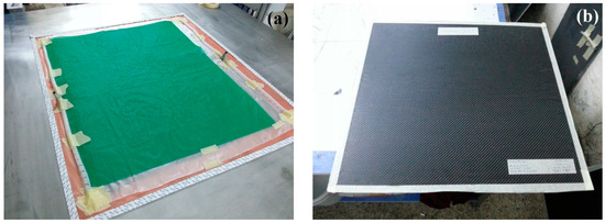
Figure 1.
Carbon-fiber-reinforced polymer (CFRP) composites: (a) VARIM method and (b) fabricated CFRP plate.

Table 1.
Mechanical and physical properties of used materials as components in the composite structure.
The used epoxy matrix was Huntsman Araldite 1564 mixed with Aradur 3487 as hardener and was prepared from Huntsman Advanced Materials in the USA. The modulus of elasticity and tensile strength of used epoxy were 3300 and 92 MPa, respectively. The CFRP homogenous composites were fabricated in Fibermak composites Ltd. CO., Izmir, Turkey. The curing process of the composites was carried out at −1 atm pressure and 80 °C, for 8 h. The schematic of the curing process is shown in Figure 2. The composite fabrication process (VARIM) and fabricated CFRP plate are shown in Figure 1.
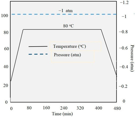
Figure 2.
Schematic of curing process of fabricated CFRP composites.
2.2. Thermal-Cycling Process
In the thermal-cycling process, one cycle was determined as a sequence which was started from room temperature and increased to +120 °C, then decreased to −40 °C and finally returned to room temperature. As Figure 3 shows, the whole thermal-cycling process time was 20 min. This sequence was repeated for 20, 40, 60 and 80 cycles.
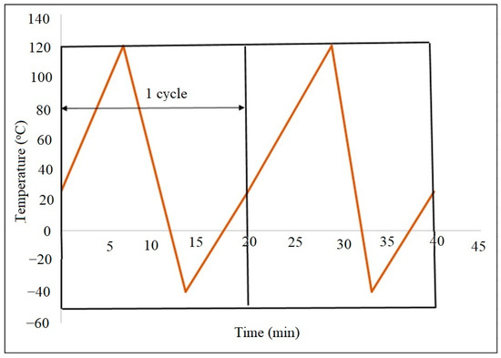
Figure 3.
Temperature profile of thermal-cycling process for two cycles.
2.3. Mechanical Tests
Mechanical experiments, such as tensile, bending and SBS tests, were carried out to investigate the effect of thermal cycling on the mechanical properties of CFRP composites by using a rectangular specimen (see Figure 4 and Table 2). Therefore, tensile strength, modulus of elasticity, flexural modulus, flexural strength and ILSS were compared for different cycled specimens at room temperature.
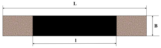
Figure 4.
Geometry of mechanical-test specimens.
Table 2.
Dimensions of test specimens for mechanical tests.
All the mechanical tests were carried out by using AGIS100 Shimadzu, Shimadzu Corporation/Japan instrument in mechanical engineering laboratory of Ataturk University, Turkey. The loading capacity of test instrument was 10 kN, and all mechanical experiments were accomplished at room temperature. According to ASTM standard, D3039, D790 and D2344 for tensile, bending and SBS tests, respectively, the cross-head speed of instrument during tensile and bending tests was 1 mm/min and for SBS test was 1.3 mm/min (see Figure 5a–c).
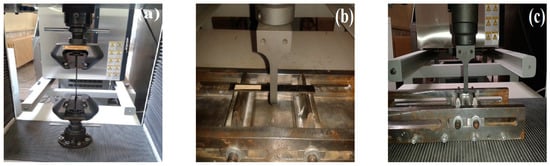
Figure 5.
Mechanical tests of fabricated composites: (a) tensile test, (b) bending test and (c) inter-laminar shear strength (ILSS) test.
The tensile strength, flexural modulus and flexural strength were calculated from Equations (1)–(3), respectively. Moreover, Equation (4) was used to calculate the ILSS from the SBS test.
where P, b and t were the maximum applied load (N), width and thickness of samples. Moreover, according to ASTM D5379, m was the slope of force-deflection diagram in the bending test. Geometrical dimensions of the test specimen, such as L, b and t, were shown in Table 2, and the maximum force was extracted from experimental tests results.
2.4. Dynamic Mechanic Analyzes (DMA)
Perkin Elmer Pyris Diamond Dynamic Mechanic Analysis instrument was used to carry out DMA test for room temperature (RT) specimens and thermal-cycling-exposure-fabricated woven CFRP composites. The DMA test is an effective technique for characterization of viscoelastic behavior of composite materials. This technique assesses the viscoelastic properties of the materials, especially composites in response to the vibrational loads. Homogenous CFRP composites were tested under three-points bending mode at 1 Hz frequency, in the temperature range between 25 and 200 °C. The heat rate in this process is 2 °C/min, and the maximum mechanical load is 18 N. The test is carried out according to ASTM D7028 standard, where the dimensions of used square samples are 7 × 7 mm2. The curves of viscoelasticity parameters, such as storage modulus (E’), loss modulus (E’’) and damping ratio (tan δ), are plotted versus temperature and evaluated by Pyris software. The viscoelastic properties, glass transition at fabricated RT and thermal exposure CFRP composites are determined by this test, as well as.
2.5. Hydrophobicity Test
The water-absorption characteristic of the fabricated CFRP composite before and after thermal cycling exposure was evaluated by using a hydrophobicity test. The water-absorption nature of the composite materials is a very important characteristic of composite materials, especially for those working in humid conditions or in direct contact with water, such as marine or aeronautic instruments. The hydrophobicity test was carried out by a KSV CAM 101 goniometer, and the contact angle for each specimen was determined at Chemical Laboratory of Kazim Karabekir Faculty of Ataturk University in Erzurum/Turkey. According to Figure 6, the material with contact angle (Ɵ) higher than 90° is from the hydrophobic type, unless it is from the hydrophilic type.
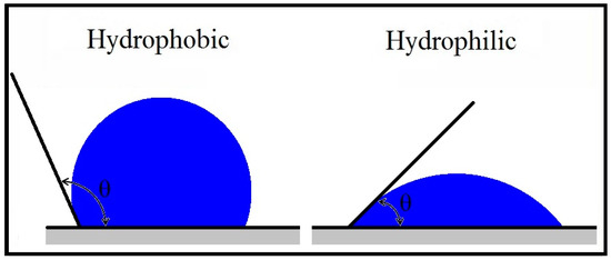
Figure 6.
Contact angle in hydrophobicity test.
3. Results and Discussion
3.1. Mechanical Tests
As mentioned in the experimental tests section, the mechanical properties of fabricated CFRP composites were evaluated by using tensile, bending and SBS tests.
3.1.1. Tensile Test
The modulus of elasticity and tensile strength of CFRP composites before and after thermal exposure are shown and compared in Figure 7.
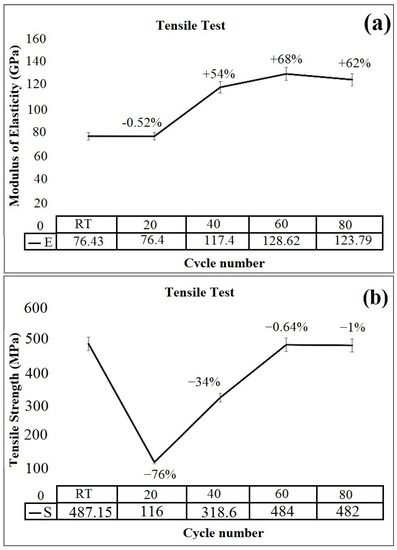
Figure 7.
Tensile test results of room temperature (RT) and thermal exposure CFRP composites, (a) modulus of elasticity, (b) tensile strength.
As illustrated in Figure 7a, the modulus of elasticity of CFRP composites was slightly declined by the initiation of the thermal-cycling process from 76.43 to 76.4 GPa. The degradation effect of thermal cycling due to CTE difference between composite components reduced modulus of elasticity by 0.52% in CFRPs after 20 cycles of exposure between −40 and +120 °C. After that, the high-temperature effects of the thermal-cycling process made a dominant behavior of thermal-cycling process and increased crosslinking. This phenomenon improved properties of CFRPs, increasing by 68% in modulus of elasticity up to 128.616 GPa for 60 cycles. After this point, the effect of degradation was dominated due to CTE difference and modulus of elasticity reduced with the amount of 3.91 GPa after 80 cycles. About the tensile strength, as shown in Figure 7b, initiation of thermal-cycling process caused to a sharp decrease from 487.15 to 116 MPa. The stress–strain curves of fabricated CFRP composites before and after 20, 40, 60 and 80 cycles were plotted in Figure 8.
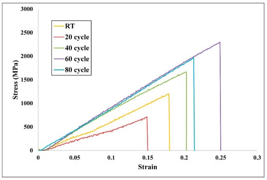
Figure 8.
Stress–strain curves of fabricated CFRP composites before and after 20, 40, 60 and 80 cycles.
Initiation of microcracks in the structure of composite due to stress concentration in the interface of composite is an important reason for this reduction. By increasing the cycles number similar to modulus of elasticity, the dominant effect of post-curing improved the mechanical properties of CFRPs. Thus, the tensile strength of the composite was increased by 75.93% up to 60 cycles. Although, after this point, the post-curing effects were subsided, and microcracks started to grow and join together. This phenomenon caused delamination occurrence and decreased the tensile strength by about 41% in 80 cycles.
3.1.2. Bending Test
To study the effect of thermal cycling on the flexural modulus and flexural strength, the flexural modulus and strength variations were investigated in RT and thermal-exposure CFRPs (see Figure 9). As shown in Figure 9a, the bending modulus was decreased by 7.45% in the beginning of the thermal-cycling process. The reduction for the 20 cycles may be related to the debonding effect of thermal cycling. In this condition, the weakening effect of thermal cycling is dominant due to the lack of the conditioning time. Thereafter, when the conditioning time increased, the flexural modulus increased, as well, which may be due to greater post-curing effects of thermal conditioning. Moreover, the elasticity modulus increased by 8.27% up to 53.8 GPa after 60 cycles. The enhancement of flexural modulus did not continue up to 80 cycles of exposure. This could be related to higher thermal stresses that started dominating over the cryogenic compressive stresses for the longer conditioning of the thermal-cycling process. In the case of flexural strength, similar to the flexural modulus, initiation of thermal cycling decreased it from 489.6 MPa for RT condition to 426.94 MPa after 20 cycles of exposure. Thereafter, the post-curing effects started to dominate and increased the flexural strength by 16.48% after 60 cycles of exposure. At the longer conditioning of thermal cycling, the effect of post-curing, due to the high temperature in the cycling process, enhanced the crosslinking and led to increasing the flexural strength up to 495.21 MPa.
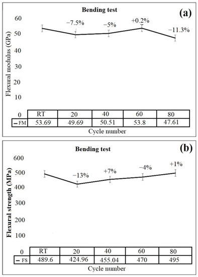
Figure 9.
Bending test results of RT and thermal exposure CFRP composites, (a) flexural modulus, (b) flexural strength.
3.1.3. SBS Test
Voids or porosities are created if air is trapped inside the molded part. Such voids considerably deteriorate the ILSS magnitudes of fabricated composites. The ILSS values of CFRP composites at RT and after thermal cycling exposure are shown in Figure 10.
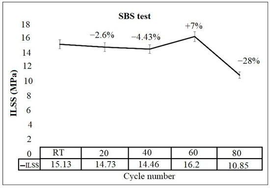
Figure 10.
ILSS values of RT and thermal-cycling-exposure CFRP composites.
As shown in Figure 10, the shear strength was decreased slightly by the initiation of the thermal-cycling process up to 40 cycles. There was an initial reduction in ILSS for conditioning time up to 40 cycles and then an increment with increasing thermal-cycle numbers. In this condition, thermal cycling caused debonding, which resulted in the reduction of ILSS values. A low degree of post-curing strengthening was the result of the low conditioning time. When the thermal-cycles number increased to 60 cycles, the ILSS raised up to 16.2 MPa. Growing the ILSS value by rising cycle numbers may be due to the higher order of further polymerization. Development of stronger bonds at the fiber/matrix interface due to high-temperature conditioning during the thermal-cycling process, which increased the shear strength, may be the other reason for the ILSS enhancement [4]. After 60 cycles, development of compressive stresses due to quenching and also the debonding effect of thermal cycling caused the manifestation of residual stresses in the interface and reduced the stress transmissibility. This phenomenon increased thermal stress concentration in the interface region and decreased shear strength by 33.02%.
3.2. Thermal Test
3.2.1. DMA Test
The evaluation of the viscoelastic properties of RT and thermal-exposure CFRP composites was carried out by a DMA test. To this, the curves of viscoelastic properties, such as storage modulus, loss modulus and loss factor (tan δ), were plotted for fabricated RT and thermal-treated CFRP samples in Figure 11.
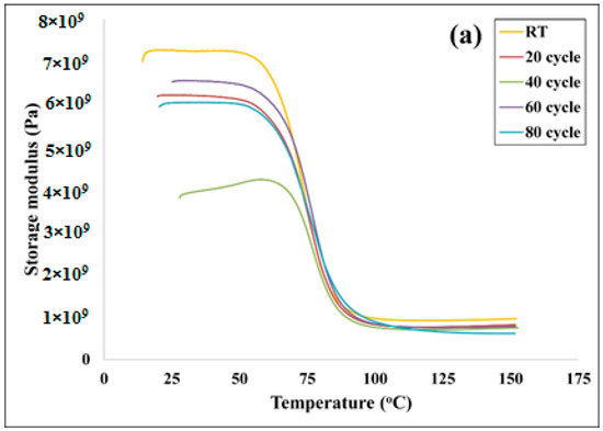
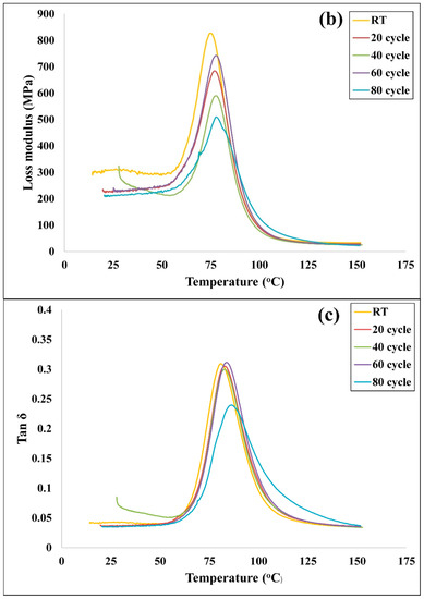
Figure 11.
DMA results of RT and thermal-cycling-exposure CFRP samples: (a) storage modulus, (b) loss modulus and (c) loss factor.
The composite materials subjected to the DMA test are categorized in three states, namely glass, glass transition and rubbery states. In the glassy state, segmental mobility is limited in the structure of material, and the material has the highest storage modulus. In the glass transition state, the storage modulus is decreased steeply by partially changing in temperature. Glass transition temperature, which is known as one of the most important characteristics of polymeric composites, is determined by the analysis of the transition region. Moreover, the data attained from this state are used to characterize the viscoelastic properties of polymer composites. The final section of the DMA curve includes a rubbery state, where the storage modulus does not have considerable variation [18]. As shown in Figure 11a, the original sample of CFRPs gained the highest storage modulus in the glassy state. As it is clear, the loss modulus shows the viscous properties of a polymeric based material and is a criterion for energy loss as heat or dissipated during one cyclic load as well. It is worth mentioning that the loss modulus was almost steady at a low temperature and reached a peak value at the onset temperature, showing the maximum heat dissipated per unit deformation. The values of glass transition temperature and the maximum value of tanδ for CFRP composites in different thermal cycles extracted from the DMA traces are given in Table 3. It is observed that the Tg and tanδ for 40 cycles is the lowest. On the other hand, the sample exposed to 80 cycles gained the highest Tg. This phenomenon is similar to the results of flexural test, where the sample exposed to 80 cycles and gained the highest flexural strength because of the further effect of crosslinking [19].
Table 3.
Glass transition temperature and loss factors of RT and thermal-exposure CFRP composites.
3.2.2. Hydrophobicity Test
The hydrophobicity test results of original RT and thermal-cycle-exposure CFRP composites are shown in Figure 12 and Table 4. According to the results, the contact angle of original CFRP is 80.87°, indicating that the CFRP is from hydrophilic type and tends to be hydrophobic in nature due to the high hydrophobicity of carbon fibers. The contact angle of CFRP samples is slightly reduced by increasing the thermal cycles and the water-absorption capability. This phenomenon occurs due to evaporation of solvents of epoxy and increasing water-absorption nature of the matrix material. According to Figure 12, by increasing cycle numbers, especially from 60 to 80 cycles, the water-absorption desire of composite is reduced. The results reveal that the thermal-cycling process not only does not change the water-absorption nature of CFRP composites but also intensifies their hydrophilic nature.
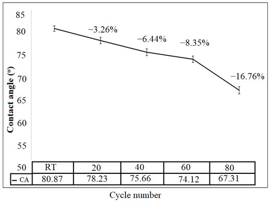
Figure 12.
The contact angles and changing of them by increasing cycle numbers in thermal-cycling process.
Table 4.
Contact angle and nature of RT and thermal-cycling-exposure CFRP composite materials.
3.3. Scanning Electron Microscopy (SEM)
The effect of thermal-cycling shock on microstructure of CFRP composite was evaluated by SEM micrographs (Figure 13).
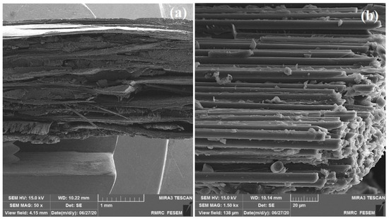
Figure 13.
SEM micrographs of fracture surfaces of CFRP composites: (a) 50× and (b) 1.5k×.
SEM was also used to see the fracture surfaces. A small section of cross-section of composite laminates exposed to tensile test after thermal cycling was prepared for SEM observation. As shown in Figure 13, different failure modes were observed in tested specimens after 80 cycles between −40 and 120 °C. The fracture surfaces showed a macroscopic brittle character. According to Figure 13a, layer delamination is obvious, which occurred due to thermal cycling and difference of CTE for carbon fiber and epoxy matrix. This delamination nucleated and propagated some microcracks. In the other words, delamination was created during deformation due to the temperature variation and different behaviors of matrix and fiber. This phenomenon acted as a stress concentrator to initiate and propagate cracks under tensile loading. According to fracture surfaces, as shown in Figure 13, the delamination in composite layers, fiber pull-out due to weakness of bonds between fibers and polymer and bundle breakage were the dominant modes for the fracture in tensile-tested specimens.
4. Conclusions
The effect of thermal cycling on the mechanical and thermal properties of CFRP composites were studied. Mechanical tests such as tensile, bending and SBS were carried out, to characterize the mechanical properties, and a DMA test was also done, to evaluate the thermal effect of thermal cycling. It was concluded that the thermal cycling affected the polymer composites in two ways. First, it caused degradation because of CTE difference in composite components and manifestation of thermal-residual stress in the interface region that caused a debonding effect. Second, it increased crosslinking due to polymerization, which improved the interface behavior and mechanical characteristics of composite materials. As a result, the interaction of these mechanisms was very complex and indicated the material behavior at this condition. According to the results of the DMA test, the viscoelastic properties of CFRPs were not significantly affected by the increasing of thermal cycles. According to the hydrophobicity test results, the CFRP had hydrophilic nature, and its exposure to thermal cycling did not affect the nature of composite. In this regard, the contact angle of thermal-treated materials was slightly decreased by increasing cycle numbers. According to the SEM micrographs delamination, fiber pull-out and bundle breakage were the dominant modes for the fracture in the tensile test for CFRP composites.
Author Contributions
F.A.-S., conceptualization, investigation, methodology, data curation and writing—original draft; H.A., supervision; M.A.M.-B., investigation, data curation, formal analysis and writing—review and editing. All authors have read and agreed to the published version of the manuscript.
Funding
This research was financially supported by the Scientific and Technological Research Council of Turkey (TUBITAK), Project No. 213M600, and Ataturk University Scientific Research Grant, BAP 2012/448.
Data Availability Statement
The data presented in this study are available on request from the corresponding author.
Acknowledgments
The authors would like to thank Özgür Seydibeyoğlu and Volkan Acar for their scientific contributions.
Conflicts of Interest
The authors declare no conflict of interest.
References
- Liu, Z.; Chen, P.; Han, D.; Lu, F.; Yu, Q.; Ding, Z. Atmospheric air plasma treated PBO fibers: Wettability, adhesion and aging behaviors. Vacuum 2013, 92, 13–19. [Google Scholar] [CrossRef]
- Bora, M.O.; Çoban, O.; Sinmazcelik, T.; Gunay, V. Effect of Fiber Orientation on Scratch Resistance in Unidirectional Carbon-Fiber-Reinforced Polymer Matrix Composites. J. Reinf. Plast. Compos. 2009, 29, 1476–1490. [Google Scholar] [CrossRef]
- Segerström, S.; Ruyte, E. Effect of thermal cycling on flexural properties of carbon-graphite fiber-reinforced polymers. Dent. Mater. 2009, 25, 845–851. [Google Scholar] [CrossRef] [PubMed]
- Ray, B.C. Effect of thermal shock on interlaminar strength of thermally aged glass fiber-reinforced epoxy composites. J. Polym. Sci. 2006, 100, 2062–2066. [Google Scholar] [CrossRef]
- Kot, P.; Baczmański, A.; Gadalińska, E.; Wroński, S.; Wroński, M.; Wróbel, M.; Bokuchava, G.; Scheffzük, C.; Wierzbanowski, K. Evolution of phase stresses in Al/SiCp composite during thermal cycling and compression test studied using diffraction and self-consistent models. J. Mater. Sci. Technol. 2020, 36, 176–189. [Google Scholar] [CrossRef]
- Mikata, Y.; Taya, M. Stress Field in a Coated Continuous Fiber Composite Subjected to Thermo-Mechanical Loadings. J. Compos. Mater. 1985, 19, 554–578. [Google Scholar] [CrossRef]
- PapanicolaouK, G.C.; Xepapadaki, A.G.; Pavlopoulou, S.; Zaoutsos, S.P. On the investigation of the stress threshold from linear to nonlinear viscoelastic behaviour of polymer-matrix particulate composites. Mech. Time Depend. Mater. 2009, 13, 261–274. [Google Scholar] [CrossRef]
- Grzegorz, K.; Tomasz, N.; Robert, S. Modeling and Prediction of Thermal Cycle Induced Failure in Epoxy-Silica Composites. Appl. Compos. Mater. 2012, 19, 65–78. [Google Scholar]
- Chu, I.; Lee, Y.; Amin, M.N.; Jang, B.-S.; Kim, J.-K. Application of a thermal stress device for the prediction of stresses due to hydration heat in mass concrete structure. Constr. Build. Mater. 2013, 45, 192–198. [Google Scholar] [CrossRef]
- Chen, J.; Chen, J.J.; Jin, W.L. Experiment investigation of stress concentration factor of concrete-filled tubular T joints. J. Steel Res. 2010. [Google Scholar] [CrossRef]
- Ramanujam, N.; Vaddadi, P.; Nakamura, T.; Singh, R.P. Interlaminar fatigue crack growth of cross-ply composites under thermal cycles. Compos. Struct. 2008, 85, 175–187. [Google Scholar] [CrossRef]
- Guerrero, J.; Mayugo, J.A.; Costa, J.; Turon, A. Failure of hybrid composites under longitudinal tension: Influence of dynamic effects and thermal residual stresses. Compos. Struct. 2020, 233, 111732. [Google Scholar] [CrossRef]
- Russell-Stevens, M.; Todd, R.; Papakyriacou, M. Microstructural analysis of a carbon fibre reinforced AZ91D magnesium alloy composite. Surf. Interface Anal. 2005, 37, 336–342. [Google Scholar] [CrossRef]
- Azimpour-Shishevan, F.; Akbulut, H.; Mohtadi-Bonab, M.A. Effect of thermal cycling on mechanical and thermal properties of basalt fibre-reinforced epoxy composites. Bull. Mater. Sci. 2020, 43, 1–10. [Google Scholar] [CrossRef]
- Wang, Q.; Zhou, D.; Chen, Y.; Eames, P.; Wu, Z. Characterization and effects of thermal cycling on the properties of paraffin/expanded graphite composites. Renew. Energy 2020, 147, 1131–1138. [Google Scholar] [CrossRef]
- Yang, B.; Yue, Z.; Wang, P.; Gan, J.; Liao, B. Effects of space environment temperature on the mechanical properties of carbon fiber/bismaleimide composites laminates. Proc. Inst. Mech. Eng. Part G J. Aerosp. Eng. 2017, 232, 3–16. [Google Scholar] [CrossRef]
- Shin, Y.C.; Novin, E.; Kim, H. Electrical and thermal conductivities of carbon fiber composites with high concentrations of carbon nanotubes. Int. J. Precis. Eng. Manuf. 2015, 16, 465–470. [Google Scholar] [CrossRef]
- Wang, C.; Smith, L.M.; Wang, G.; Shi, S.Q.; Cheng, H.; Zhang, S. Characterization of interfacial interactions in bamboo pulp fiber/high-density polyethylene composites treated by nano CaCO3 impregnation modification using fractal theory and dynamic mechanical analysis. Ind. Crop. Prod. 2019, 141, 111712. [Google Scholar] [CrossRef]
- Azimpour-Shishevan, F.; Akbulut, H.; Mohtadi-Bonab, M.A. Low Velocity Impact Behavior of Basalt Fiber-Reinforced Polymer Composites. J. Mater. Eng. Perform. 2017, 32, 337–2900. [Google Scholar] [CrossRef]
Publisher’s Note: MDPI stays neutral with regard to jurisdictional claims in published maps and institutional affiliations. |
© 2021 by the authors. Licensee MDPI, Basel, Switzerland. This article is an open access article distributed under the terms and conditions of the Creative Commons Attribution (CC BY) license (http://creativecommons.org/licenses/by/4.0/).