Abstract
Taking into consideration the seismic vulnerability of older buildings and the increasing need for reducing their carbon footprint and energy consumption, the application of an innovative system is investigated; the system is based on the use of textile-reinforced mortar (TRM) and thermal insulation as a means of combined seismic and energy retrofitting of existing masonry walls. Medium-scale tests were carried out on masonry walls subjected to out-of-plane cyclic loading. The following parameters were investigated experimentally: placement of the TRM in a sandwich form (over and under the insulation) or outside the insulation, one-sided or two-sided TRM jacketing and/or insulation, and the displacement amplitude of the loading cycles. A simple analytical method is developed and found in good agreement with the test results. Additionally, numerical modeling is carried out and also found in good agreement with the test results. From the results obtained in this study, the authors believe that TRM jacketing may be combined effectively with thermal insulation, increasing the overall strength and energy efficiency of the masonry panels in buildings.
1. Introduction
Masonry walls represent a significant hazard to life safety because they are prone to failure during high- or moderate-intensity earthquakes. In addition, structural decay due to cumulative seismic-induced damage or to ageing poses a threat to the preservation of masonry structures that comprise a significant part of the cultural heritage in many countries. Therefore, there is a pressing need for upgrading existing masonry structures, both in non-seismic regions, e.g., due to the introduction of more stringent design requirements and/or change of usage, and in seismic regions, where they have to meet higher performance levels demanded by current seismic design codes.
A number of methods have been developed aiming at increasing the strength and/or deformation capacity of masonry walls. The relatively new class of composite materials, named textile-reinforced mortar (TRM), are quite promising, as they combine the favorable properties offered by fiber-reinforced polymers (FRP) (e.g., ease and speed of application, minimal change in the geometry, corrosion resistance, high strength and stiffness to weight ratio, high deformation capacity) while addressing most of the issues associated with the application of epoxy resins, e.g., [1,2,3,4,5,6].
In addition to seismic retrofitting, there is a strong need for effective solutions for the energy retrofitting of the building envelope; this is attributed to the vast energy consumption associated with the old building stock, and hence to the high environmental impact of old buildings. TRM jacketing has minimal, if any, thermal insulation capacity, while external or internal insulation has no load bearing capacity. In this study, we propose the integration of the two systems into a single unit, which provides both energy and seismic upgrading. In this integrated system (Figure 1), the insulating material is combined with the TRM as a single unit, which may be either constructed in situ or in the form of a prefabricated board. Depending on the constructability requirements and the aesthetics, the system may be placed either on one side of existing masonry walls or on both [7]. The TRM may be placed between the insulation and the masonry wall or outside the insulating material. These concepts are investigated experimentally, analytically, and numerically in the present study, for the case of masonry walls subjected to out-of-plane cyclic loading. More details on the experimental part for the case of out-of-plane loading, and also related to in-plane loading, are given in [8,9]. The experimental results are found in good agreement with analytical modeling as well as finite element modeling; both modeling approaches may be used in future studies to perform detailed parametric analyses. Further studies on the proposed technique are reported in [10,11].
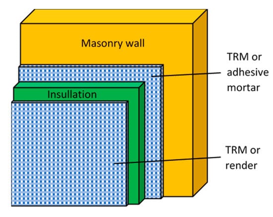
Figure 1.
Schematic view of combined structural and energy retrofitting system on one side of the masonry wall.
2. Experimental Work
2.1. Οut-of-Plane Loading
A total number of 12 wall specimens with a length of 1500 mm, a width of 400 mm, and a thickness of 85 mm were constructed using ridge-faced, 12-hole, horizontally perforated clay bricks and a general-purpose masonry cement mortar. One specimen was used as control (M), without TRM or insulation (Figure 2a). The TRM was made of a balanced textile with polymer-coated glass fiber rovings in two orthogonal directions and a cementitious mortar. The insulation material was made of EPS plates at a thickness of 20 mm. All details about the material properties and method of application are given in [8].
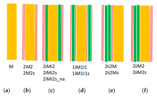
Figure 2.
Cross section of specimens for out-of-plane loading: (a) M; (b) 2M2 or 2M2s; (c) 2iMi2 or 2iMi2s or 2iMi2s_na; (d) 1i1M1i1 or 1i1M1i1s; (e) 1ii1M or 2ii2Ms; and (f) 2iiM2 or 2iiM2s.
Six different specimen designs were made:
(1) Specimens 2M2 and 2M2s retrofitted on both sides with TRM containing two layers of textile and no insulation (Figure 2b).
(2) Specimens 2iMi2 and 2iMi2s retrofitted on both sides with one layer of insulating material and TRM containing two layers of textile; the insulation was placed between the masonry and the TRM (Figure 2c).
(3) Specimens 1i1M1i1 and 1i1M1i1s retrofitted on both sides with TRM containing one layer of textile on the wall, one layer of insulating material, and a second TRM with one layer of textile placed outside the insulation (Figure 2d).
(4) Specimens 2ii2M and 2ii2Ms retrofitted on one side only, with a sandwich system comprising a core with two layers of insulation material and TRM faces with two layers of textile (Figure 2e).
(5) Specimens 2iiM2 and 2iiM2s with two layers of insulation material on one side and TRM with two layers of textile on the outside (Figure 2f).
(6) Specimen 2iMi2_na as in (2) above (Figure 2c), but with retrofitting materials non-anchored, that is, not extending all the way to the end of the walls, so that they were not clamped between the end supports and the masonry.
All specimens, except the ones in design (6), were tested in pairs, corresponding to two different displacement amplitudes of the loading cycles (1 and 2 mm).
The notation of specimens comprises a series of letters and numbers. The numbers “1” or “2” indicate the number of layers in the textile, “M” stands for masonry, and “i” stands for insulation. The sequence of letters and numbers represents the sequence of the different materials in each specimen. The symbol “s” at the end of the notation stands for “small” displacement amplitude (1 mm). The control specimen is denoted as M.
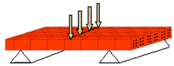
2.1.1. Test Setup, Instrumentation, and Procedure for Out-of-Plane Loading
All specimens were subjected to cyclic out-of-plane loading using a stiff steel frame. The walls were laid horizontal and were loaded in three-point bending at a span of 1.30 m (Figure 3). Two pairs of steel hinges were placed at each support (along the specimens’ width, at top and bottom), and a third pair was placed at mid-span, along the load application line.
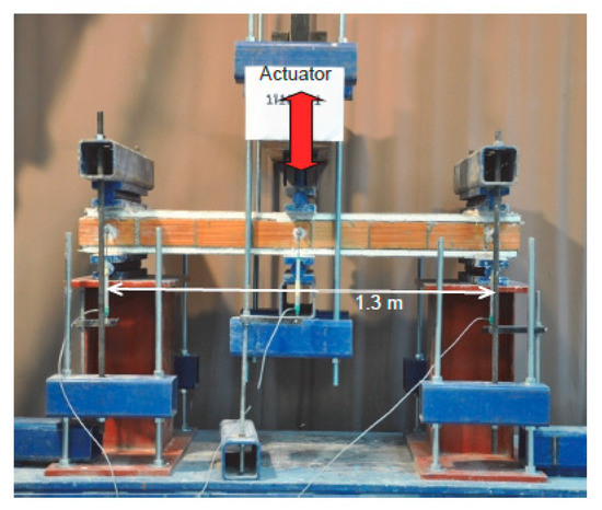
Figure 3.
Experimental setup for out-of-plane testing.
The specimens were tested by applying the load in a quasi-static cyclic pattern of controlled displacements, at a rate of 0.1 mm/sec. The loading scenario consisted of cycles at a series of progressively increasing displacement amplitudes in both the push and pull directions. The displacement amplitude increment was either 2 or 1 mm, and a single loading cycle was applied for each amplitude level.
2.1.2. Experimental Results for Out of-Plane Loading
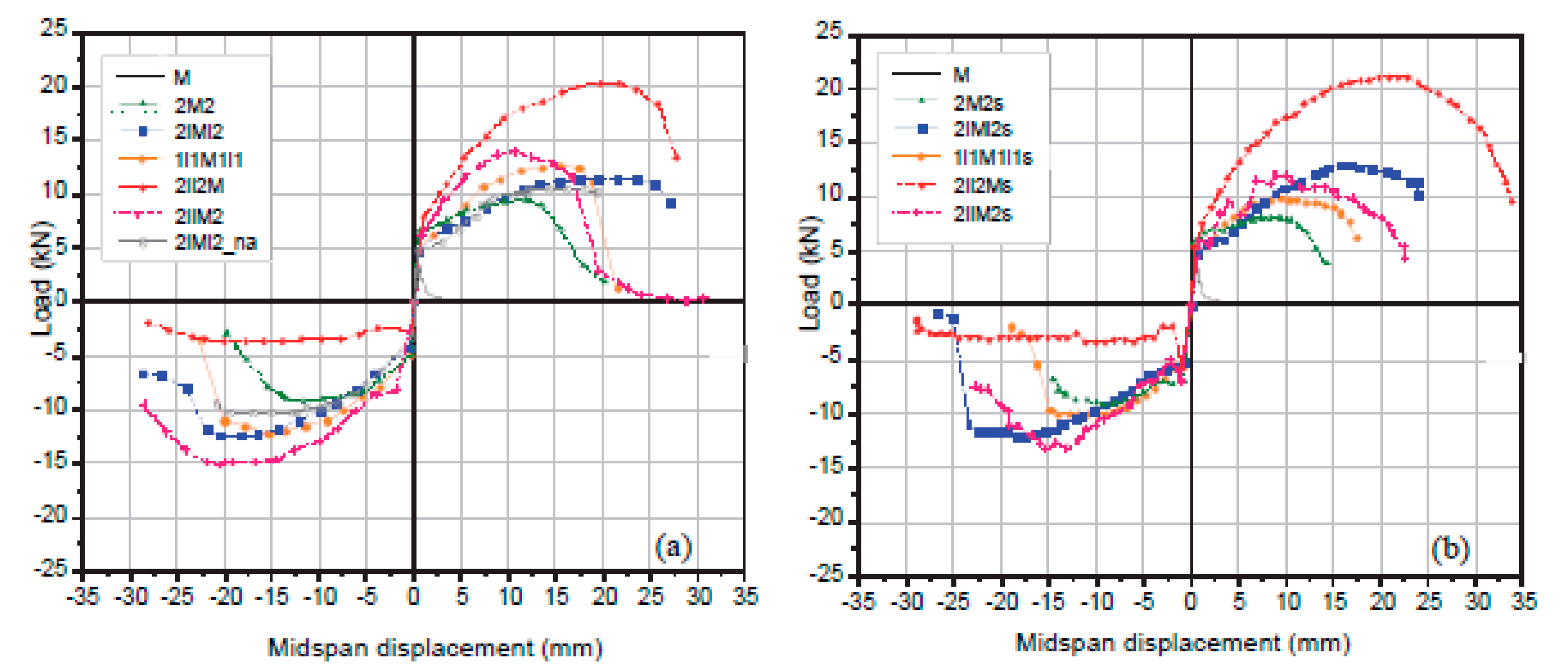
The load versus displacement envelope curves of the hysteresis loops for specimens are given in Figure 4. Typical photographs of failure mechanisms are given in Figure 5. Peak load values in the push and pull directions, mid-span displacements at failure, cumulative energy dissipation capacity, and observed failure modes are given in Table 1, for all specimens. Failure was defined at the point of the load versus mid-span displacement envelope curve where a 20% reduction in load was recorded.
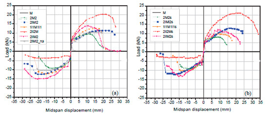
Figure 4.
Envelope curves for out-of-plane loading: (a) 2 mm displacement increment; (b) 1 mm displacement increment.
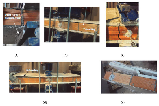
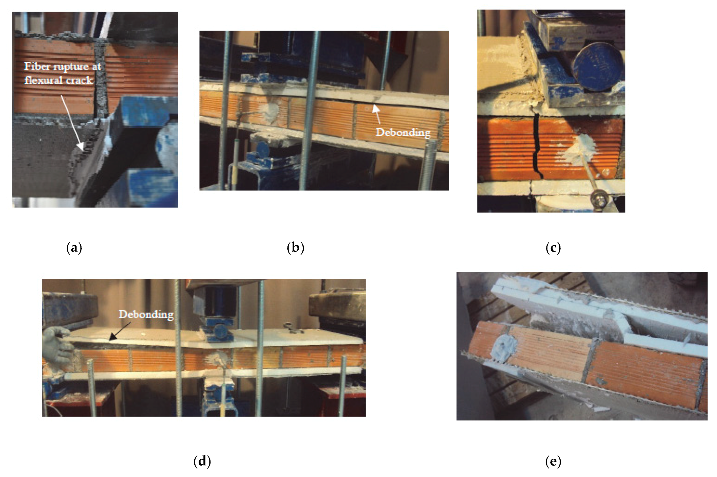
Figure 5.
(a) Fiber rupture at mid-span; (b) debonding at the interface between the masonry and the insulation; (c) flexural cracking through the insulating material; (d) debonding, as a result of unfavorable anchorage conditions; and (e) debonding at the insulation–masonry interface propagates through the two insulation layers.

Table 1.
Summary of three-point bending tests.
From the test results, it is concluded that the combined TRM/thermal insulation retrofitting scheme is highly effective. In terms of strength and deformation capacity, the combination of TRM with an insulation material yields better results than the use of TRM alone. The use of TRM without insulation increased the strength by approximately 170% (specimen 2M2), whereas this increase varied from 200% to 340% when the (double-sided) TRM was combined with thermal insulation, due to the increased lever arm of the tension reinforcement. The respective numbers for specimens type “s” (small displacement amplitude increment) are 135%, 190%, and 285%. Jackets with unfavorable bond conditions (specimen 2iMi2_na) were less effective, as expected. They increased the strength by at about 200%, whereas the strength increase in the case of favorable bond conditions (specimen 2iMi2) was about 235%.
With regard to deformation capacity, as quantified by the mid-span displacement at failure, thermal insulation combined with TRM jacketing was much more effective than the TRM system alone in all cases, by up to 140–145%.
2.2. Bond Tests
For the investigation of bond-related failure modes, bond–slip tests were carried out, according to the setup described in [12]. Masonry specimens were constructed using the same (as described above) 12-hole, horizontally perforated clay bricks and a general-purpose masonry cement mortar covered with EPS insulation and TRM reinforcement on the outer surface (Figure 6a). A total of 8 different bond lengths of the reinforcement insulation were tested (Figure 6b). The specimens had lengths of 150, 190, 255, 300, 355, 410, 520, and 640 mm, with common width for all specimens equal to 85 mm. The thickness of masonry, insulation material, and TRM was equal to 85, 20, and 10 mm, respectively.
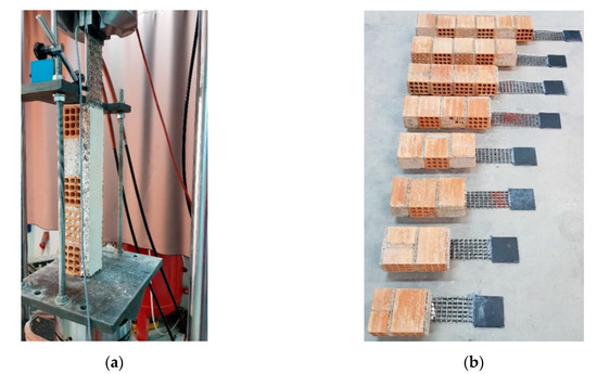
Figure 6.
Shear testing: (a) bond–slip testing of the retrofiting system; (b) specimen geometry.
A total of 24 tests were performed in an attempt to identify the failure modes, estimate the effective bond length of the retrofitting system, and calculate the mean bond strength. The TRM was intentionally over-designed with 3 layers of glass textile, so as to avoid fiber rupture and result in debonding failure. The glass fiber textile had a density of 435 g/m2 and nominal thickness (i.e., based on smeared distribution of fibers) equal to 0.18 mm; these values were calculated from the total volume of fibers in the loading direction. The same mortar used to impregnate the textile was also used to bond the insulation on the masonry. The EPS insulation used had σ10% = 200 kPa compressive strength at 10% strain and the TRM tension strength was fTRM,t = 550 MPa.
The bond tests were performed with the load and displacement measured using a load cell and digital image correlation (DIC); an extra linear variable differential transformer (LVDT) was added at the tip of the TRM (Figure 6a). The average shear stress was calculated by taking into account the full contact area between the insulation and masonry.
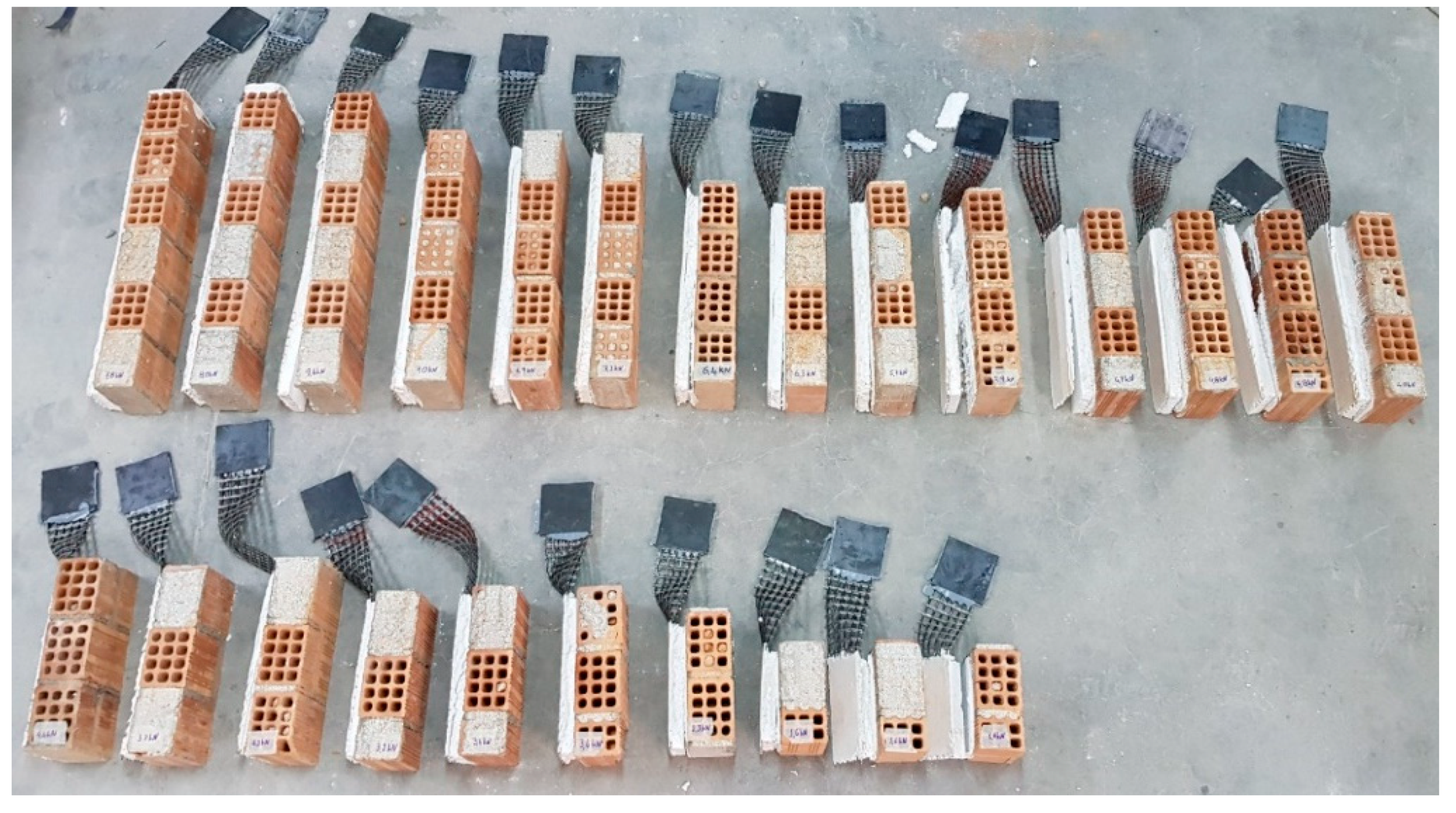
The failure modes recorded during testing (Figure 7) were as follows: (a) cohesive failure of the insulation; (b) debonding at the TRM–insulation interface; and (c) debonding at the mortar adhesive (placed on masonry)–insulation interface.

Figure 7.
Bond test specimens after testing.
Cohesive failure of the insulation was the most common failure mode. Notably, this mechanism is the most desirable too, since all others are associated with an inadequate or unsuitable bonding material for the insulation foam. The experimental results, summarized in Table 2 and Figure 8, show that the bond strength is more or less independent of the bond length, even if this length reaches relative high values. This is particularly so for bond lengths higher than approximately 250 mm. The explanation for this lies in the fact that the modulus elasticity of EPS foam (EEPS = 2–20 MPa) is much lower compared to the moduli of TRM (Etrm = 2000–3000 MPa) and masonry walls (Ew = 2000–3000 MPa), and hence shear stress in the EPS may be taken as nearly constant.
Table 2.
Average shear strength of bond specimens.
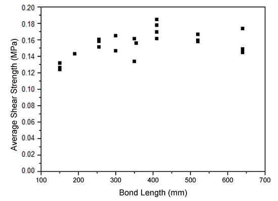
Figure 8.
Average shear strength for different bonded lengths of the retrofitting system.
3. Simplified Failure Analysis for Specimens Subject to Out-of-Plane Bending
The retrofitted wall is considered a sandwich panel that is analyzed on the basis of the simplifying assumption of Euler–Bernoulli beam theory with full shear connection [13]. For failure analysis, the section is considered cracked and the tensile strength of the masonry is neglected. The analysis accounts for three failure mechanisms: (a) tension failure of TRM in the tension zone; (b) compression failure of masonry in the compression zone, before or after the TRM fails in compression; and (c) debonding. The dominant failure mode is the one that corresponds to the lowest load. Other failure mechanisms, such as transverse shear or local buckling, were not considered, since they were not recorded in the experimental campaign.
3.1. Tension Failure of TRM or Compression Failure of Masonry
This type of failure occurs when the compression strength of the brick or TRM layer is reached or when the tension strength of the TRM is reached. The moment of resistance of the mid-span section of each specimen is calculated using classical bending theory considering linear strain distribution and force equilibrium. This theory assumes the plane section and neglects shear deformations. An example of cross-section strain and stress profiles analysis is given in Figure 9 (the location of the neutral axis is indicative, at an arbitrary depth).
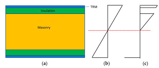
Figure 9.
(a) Cross-section, (b) strain profile, and (c) stress profile.
Masonry is assumed linear elastic in compression up to a failure strain εwu. The contribution of mortar to the tensile capacity of TRM is neglected; hence, TRM is modeled as linear elastic in tension up to a failure strain εtu, controlled by the capacity of the fibers. The contribution of fibers in TRM subject to compression is neglected; hence, TRM in compression is modeled as plain mortar, which behaves as a linear elastic material up to a failure strain εmu. The cross-section analysis was run in this study by considering the following experimentally obtained values for ultimate strains (average values from at least six specimens for each case): εwu = 0.043, εtu = 0.015, and εmu = 0.05.
3.2. Debonding
Bond mechanisms allow transferring forces from the masonry to the foam insulation and to TRM, and hence bond failure modes have to be taken into account. In the case of TRM being applied on insulation foam panels that are pasted on masonry, bond failure mostly, but not exclusively, occurs at the foam–masonry interface and implies the complete loss of bond between the two materials. Commonly, the mortar used for the reinforcement of the textile is the same one used also for the bonding of the foam insulation panel boards on the masonry and one could expect that both these surfaces are prone to debonding. In practice, because of the way the retrofitting is applied, the masonry–insulation interface can be weaker compared to the TRM–insulation interface because of technical obstacles and manual labor imperfections that result in air pockets, material discontinuities, unequal mortar spreading and leveling, or mortar water loss due to masonry absorption. On the other hand, the TRM layer is troweled evenly on the insulation boards and a full-blown cover is easier achieved which results in a much better and effective bonding.
Usually, debonding initiates in a limited area of the strengthened element and then propagates until the composite action is lost over a major part of the length of the TRM reinforcement. Localized debonding means a reduction in the bond performance between the masonry and TRM or insulating material limited to a small area, e.g., a loss in bond length a few millimetres next to a flexural or shear crack. Therefore, localized debonding is not, in itself, a failure mode that causes a significant loss of the load carrying capacity. However, when localized debonding propagates and the composite action is lost in such a way that the TRM reinforcement is not able to carry loads anymore, bond failure is obtained. In general terms, this is also referred to as peeling off. This interfacial debonding can initiate either from the end of the reinforcement or by an intermediate flexural or flexural–shear crack.
Debonding in practice is rarely a problem because the TRM layer in a retrofitted building is continuous all over the building, covering large areas and lengths with bends around corners or doors and window openings, creating a kind of anchorage that prevents slippage or making this failure mode subsidiary. If needed, debonding may also be prevented by using mechanical anchors.
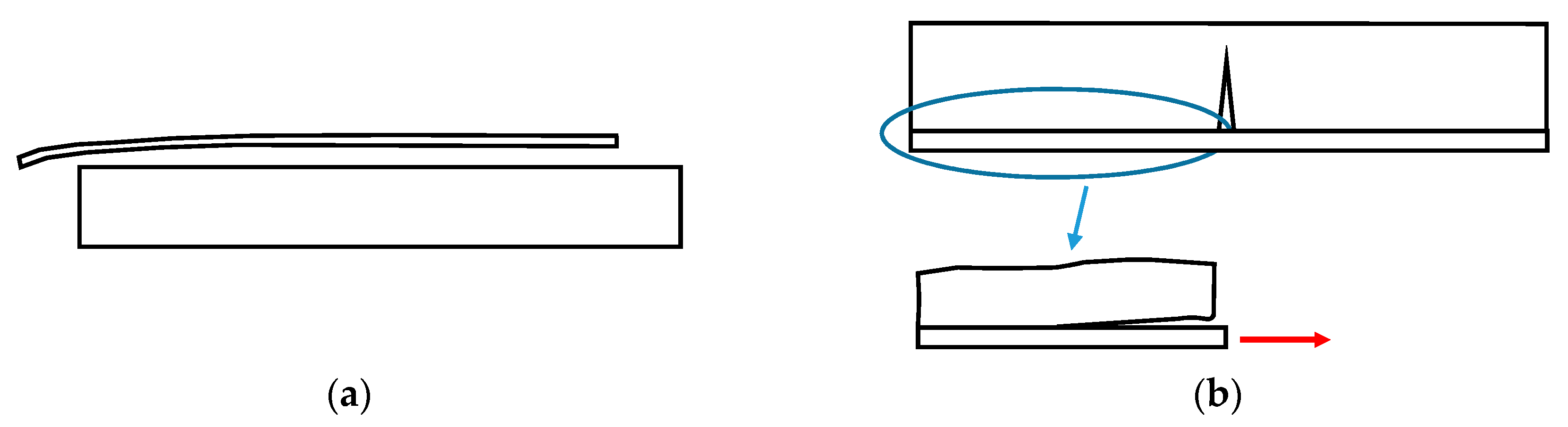
At the beam level, bond failure may occur at different TRM–insulation–masonry interfaces. Two debonding mechanisms were observed in the experimental study (Figure 10): (a) end debonding and (b) intermediate crack debonding.
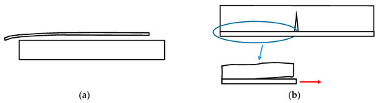
Figure 10.
Debonding mechanisms: (a) end debonding, (b) intermediate crack debonding.
In a simplified approach, end debonding may be associated with the shear strength of the weakest material, namely, the thermal insulation, and the failure load may be estimated by equating the shear stress to the bond strength obtained from bond tests (0.154 MPa in this study, see Table 2).
In another simplified approach, failure due to intermediate crack debonding may be assumed when the tensile force in the TRM at a cracked section produces a uniform distribution of shear stresses in the insulation layer along the length from the cracked section to the end support, equal to the shear strength (0.154 MPa in this study). Using this approach, cross-section analysis for a given tensile force in the TRM can yield the acting moment and hence the external load at the member failure.
3.3. Comparison of Analytical and Experimental Results
In order to calculate the theoretical load capacity of the wallettes described in the experimental part, a specialized algorithm in “MATLAB-MathWorks” was developed that runs all the failure modes described above. The results are summarized in Table 3. In this table, the experimental maximum load for each specimen is calculated for the weaker bending direction, except for the two asymmetric specimens 2ii2M and 2ii2Ms, where results are those for the strong bending direction.
Table 3.
Summary of experimental failure loads and analytical predictions.
The comparison between experimental results and analytical predictions indicates an overall good agreement. A weakness of the simplified approach is the failure to capture the mechanism of debonding in two cases (specimens 2iMi2 and 2iMi2_na).
4. Numerical Simulation
Numerical simulations for the walls tested experimentally were carried out using the finite element code ANSYS release 14.5. The analysis was monotonic, and hence the numerically obtained load–displacement results will be compared to envelope curves obtained in experimental testing.
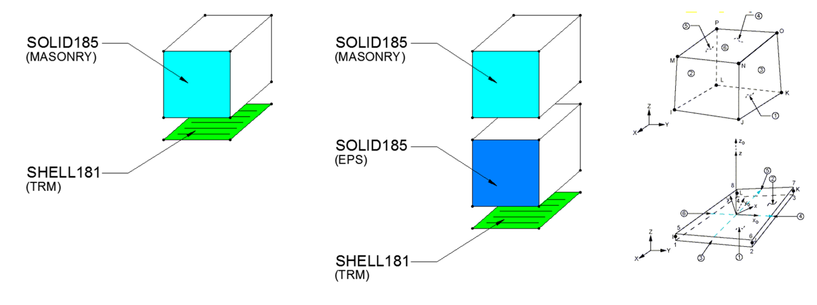
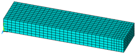
Standard SOLID185 brick elements of the ANSYS element library were used to simulate the masonry walls and the insulation panels, while SHELL181 shell elements were used for the TRM matrix. The elements arrangement and the geometry of the models for each case are presented in Figure 11 and Figure 12.
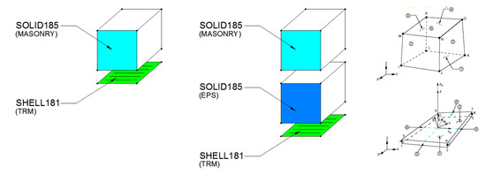
Figure 11.
Schematic of the reinforced specimen arrangement using ANSYS SOLID185 and SHELL181 elements.

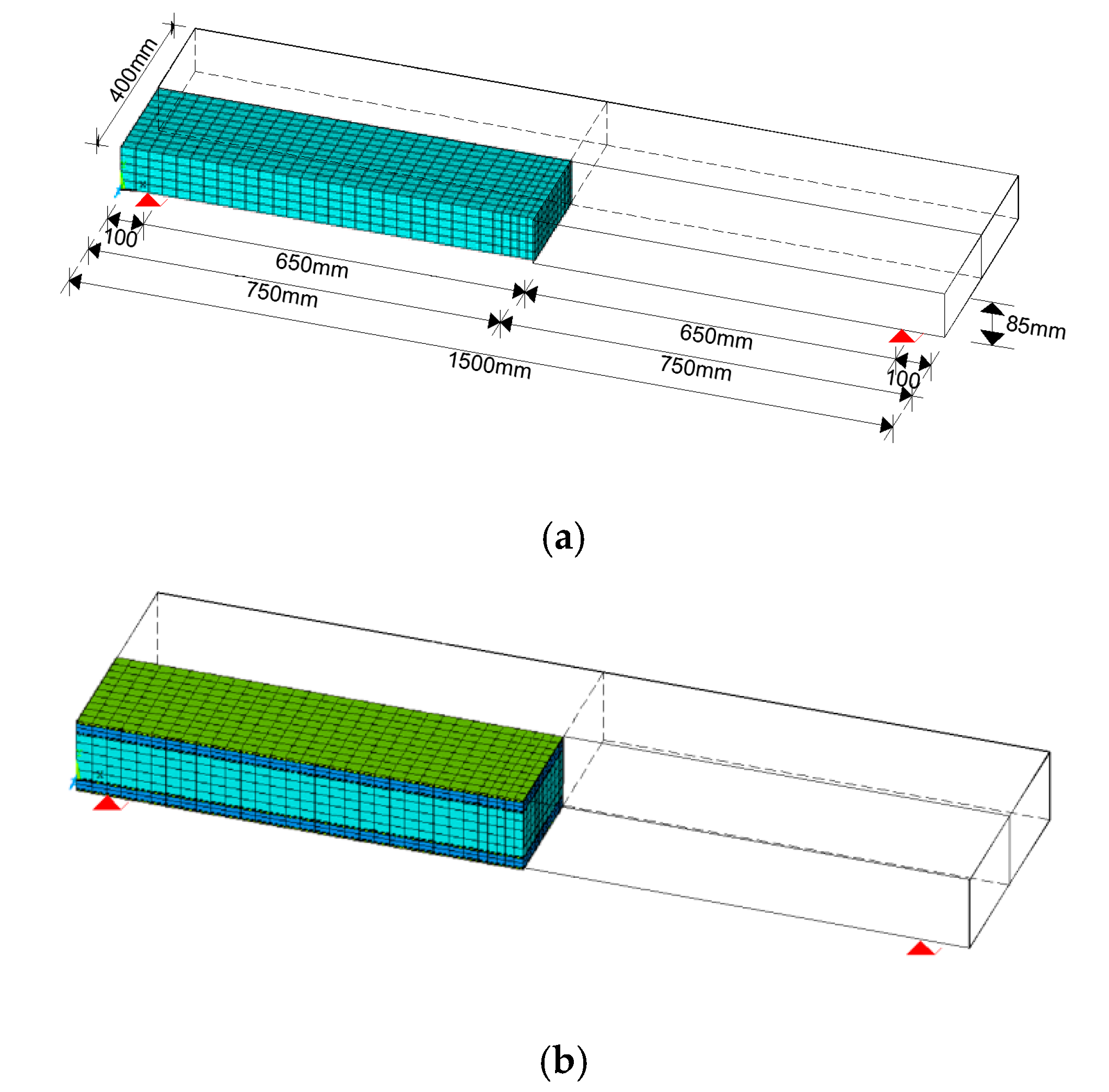
Figure 12.
(a) Schematic arrangement and geometry of control specimen and (b) model for specimen 2iMi2.
For simplicity, both the masonry wall and the insulation panels were modeled assuming isotropic homogeneous behavior (macro-model approach), while for the TRM, an orthotropic (in tension only) membrane behavior was assumed. Fully bonded interfaces were assumed between the elements. Finally, brick elements (SOLID185) with reduced integration were introduced to simulate the boundary conditions (application of loads through steel plates, see Figure 5, to avoid stress concentrations).
For analysis of the time efficiency and computational effort, a quarter of the whole specimen was constructed using the proper degree-of-freedom (DOF) constraints for symmetric conditions. A monotonic increasing vertical displacement was applied at the middle nodes in all specimens. The models that were analyzed are summarized at Table 4.
Table 4.
Out-of-plane loaded specimens and finite element models.
4.1. Mechanical Parameters
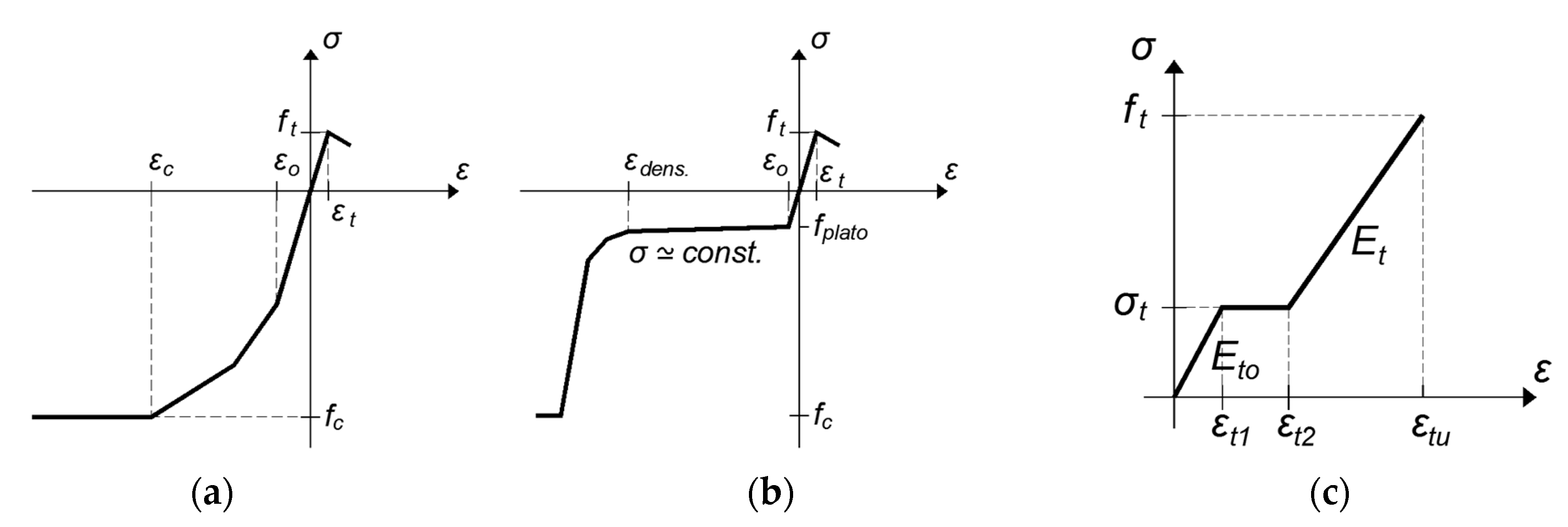
To implement the asymmetric behavior in tension and compression of the brick wall, the Cast-Iron (TB, CAST) material model expanded for brittle materials was used in ANSYS, and thus different tension and compression curves were constructed (Figure 13a). For the insulation material, the same approach was followed, treating the insulation as a cellular material with the yield point in compression followed by a long plateau with almost stable stress until very large strains leading to the densification area, as illustrated in Figure 13b.

Figure 13.
Material models for (a) masonry, (b) insulation panels, and (c) textile-reinforced mortar (TRM).
The critical behavior parameters for the masonry wall were extracted from experimental tests on masonry prisms loaded in compression, while in tension, a fraction of 10% of the compression strength was assumed. Due to the adjective limitations to simulate brittle materials, such as masonry, in tension, a calibration model for the un-reinforced specimen (M) was initially developed to fit to the experimental data the initial stiffness of un-reinforced masonry. Material parameters for the insulation panels were obtained by the materials supplier. For the TRM matrix, a multi-linear kinematic hardening (TB, MKIN) material model was adopted to capture the nonlinear behavior (Figure 13c), based on mean values from tests on TRM coupons in tension, tested for different numbers of layers and thicknesses according to each experimental group case.
The critical parameters for the constitutive law of TRM were: the initial Young modulus (Eto), the “yielding” (cracking) stress (σt), the “yielding” (cracking) strain (εt1), and the strain (εt2) where sliding of the yarns occurs until the failure of the coupon (εtu, ft).
The mechanical properties introduced in ANSYS for each material are listed in Table 5, Table 6 and Table 7. No damage criteria were introduced, and all simulations were stopped after reaching the pre-defined displacement levels.
Table 5.
Mechanical properties of the masonry wall.
Table 6.
Mechanical properties of extruded polystyrene (EPS).
Table 7.
Mechanical properties of TRM coupons.
4.2. Numerical Results and Discussion
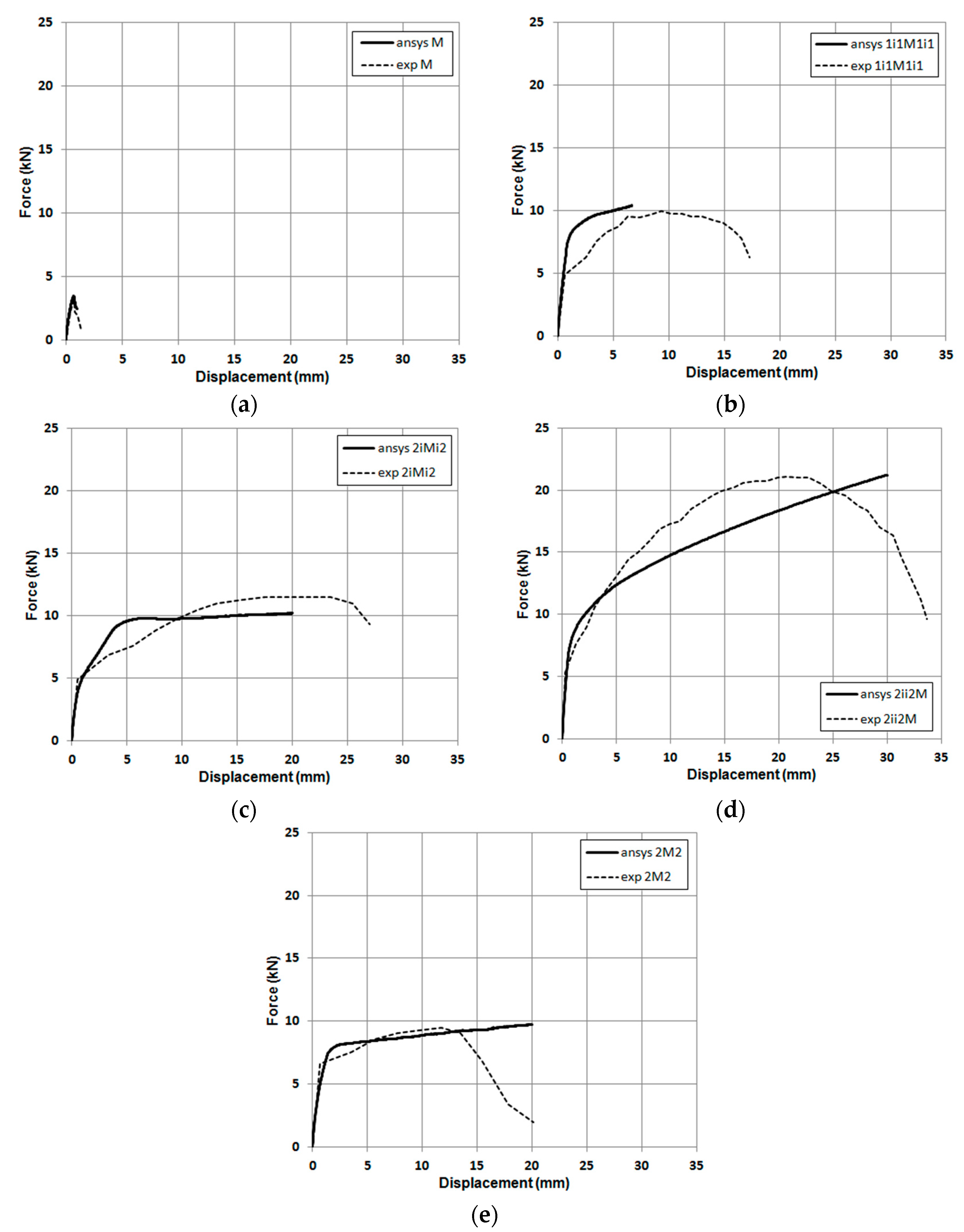
Plots of the numerical and experimental force–displacement envelope curves for the out-of-plane loaded masonry walls are presented in Figure 14.
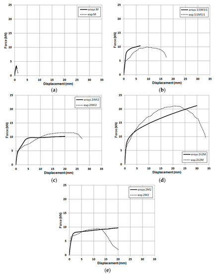
Figure 14.
Force–displacement envelope curves for the experimental versus numerical results: (a) specimen M, (b), specimen 1i1M1i1, (c) specimen 2iMi2, (d) specimen 2ii2M, (e) specimen 2M2.
Overall, despite the simplicity of the numerical approach, the numerical results showed reasonably good agreement with the experimental data, indicating that the numerical analysis is capable to reproduce the observed behavior with the exception of the post-peak reduction in strength, due to constraints of the numerical approach to simulate stress–strain curves with negative slopes. It was confirmed that all retrofitted specimens exhibited an increase in their strength and deformation capacity compared to the control. It was also confirmed that the positioning of the TRM outside the insulation panel, instead of directly on the wall, increases the lever arm of the tension reinforcement; thus, the insulated specimens showed a relatively greater increase in their strength and deformation capacity.
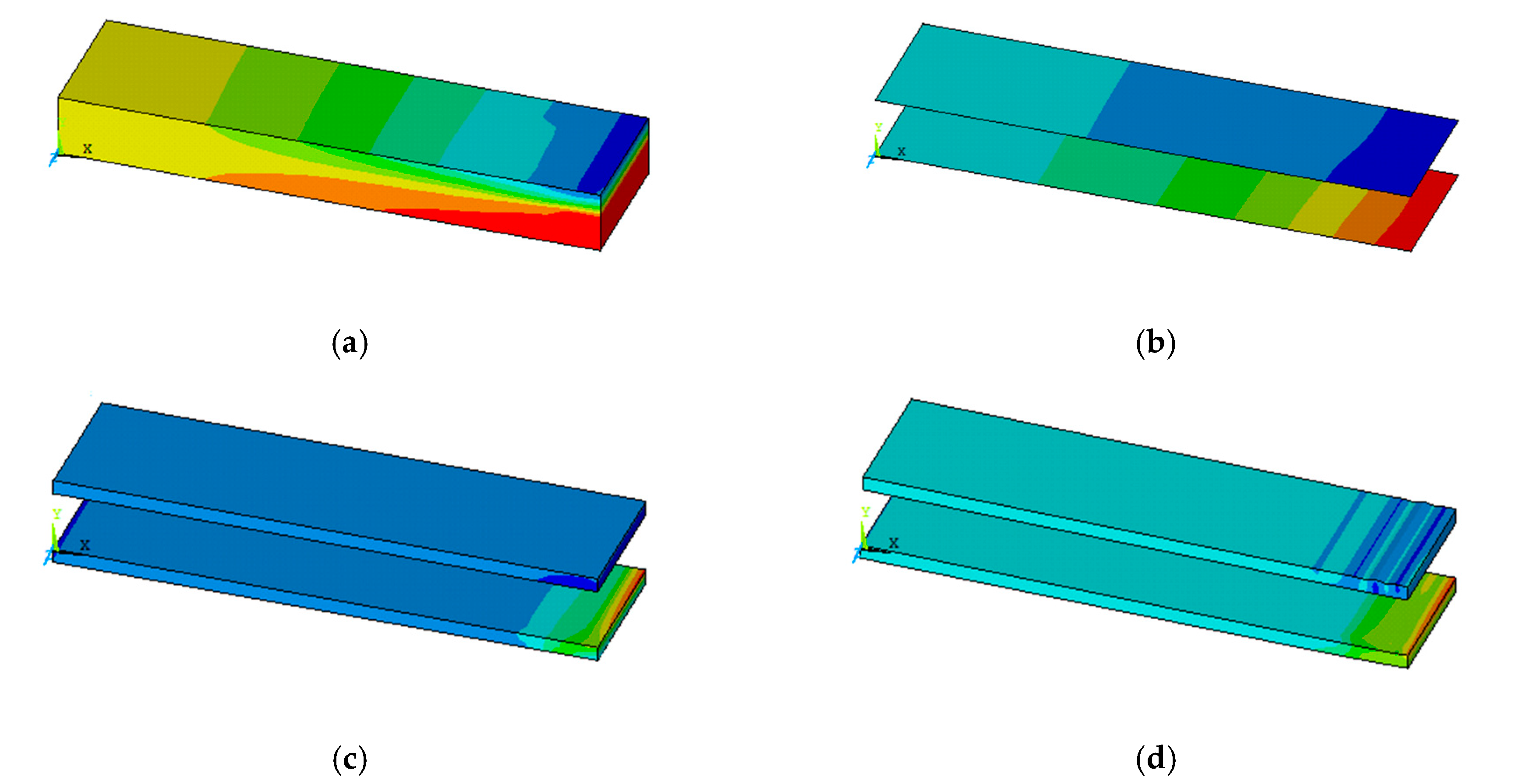
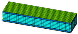
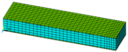
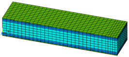
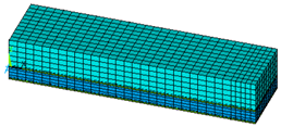
Figure 15, Figure 16 and Figure 17 illustrate, qualitatively, the strain map of the brick wall, the TRM, and the insulation panels at various displacement steps of the loading history for some of the specimens. It can be seen that the presence of TRM affects the stress distribution along the specimens, by absorbing significant amount of stress, thus leading to the increase in the overall strength and deformation capacity. Thus, the final response is more ductile compared to the brittle behavior of unretrofitted walls. The insulation panels develop significant deformations without contributing to the overall strength; their contribution is indirect, as they separate the TRM from the wall.
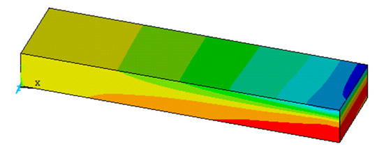
Figure 15.
Principal strain map for specimen M.
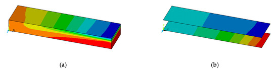
Figure 16.
Principal strain map for specimen 2M2: (a) masonry, (b) TRM.

Figure 17.
Principal strain map for specimen 2iMi2: (a) masonry, (b) TRM, (c) insulation in early loading stage, (d) insulation at the end of loading.
5. Conclusions
An innovative system for the combined seismic and energy upgrading of masonry walls is presented in this study. The system is based on the combination of textile-reinforced mortar (TRM) composites and thermal insulation materials. Testing of the system was carried out by subjecting brick masonry wallettes to out-of-plane cyclic loading, and the results were verified based on a simple analytical method as well as numerically, by simple finite element analysis.
It is concluded that, in addition to improving the thermal performance of masonry walls, the combined TRM/insulation scheme is quite effective in their seismic retrofitting for the case of out-of-plane loading, provided that proper bonding between the different layers is achieved. According to the experimental results, positioning the reinforcement outside the thermal insulation substantially improves the strength and deformation capacity when compared to TRM jacketing alone. Analytical and experimental results confirm that the prevailing failure mode is TRM tensile failure with fiber rupture. Another possibility is debonding, which could be avoided in practice through the provision of mechanical anchorage.
Simple analytical modeling based on cross-section analysis and easy to implement finite element simulations are both capable of capturing basic response characteristics. These methods could be used in future studies to optimize the proposed system and to carry out parametric studies.
Author Contributions
Conceptualization, K.K. and T.T.; methodology, K.K. and A.T.; software, A.T.; validation, K.K., A.T., and T.T.; formal analysis, K.K.; investigation, K.K.; resources, K.K.; data curation, K.K.; writing—original draft preparation, K.K.; writing—review and editing, K.K.; visualization, T.T. and A.T; supervision, T.T.; project administration, T.T.; funding acquisition, T.T. All authors have read and agreed to the published version of the manuscript.
Funding
This research was funded by European Social Fund and by Greek national funding with MIS: 5005689.
Conflicts of Interest
The authors declare no conflict of interest.
References
- Papanicolaou, C.G.; Triantafillou, T.C.; Papathanasiou, M.; Karlos, K. Textile reinforced mortar (TRM) versus FRP as strengthening material of URM Walls: Out-of-plane cyclic loading. Mater. Struct. 2008, 41, 143–157. [Google Scholar] [CrossRef]
- Harajli, M.H.; ElKhatib, H.; San-Jose, J.T. Static and cyclic out-of-plane response of masonry walls strengthened using textile-mortar system. J. Mater. Civ. Eng. 2010, 22. [Google Scholar] [CrossRef]
- Babaeidarabad, S.; De Caso y Basalo, F.; Nanni, A. Out-of-plane behavior of URM walls strengthened with fabric-reinforced cementitious matrix composite. J. Compos. Constr. 2013, 18. [Google Scholar] [CrossRef]
- De Santis, S.; De Canio, G.; de Felice, G.; Meriggi, P.; Roselli, I. Out-of-plane seismic retrofitting of masonry walls with Textile Reinforced Mortar composites. Bull. Earthq. Eng. 2019, 17, 6265–6300. [Google Scholar] [CrossRef]
- Meriggi, P.; de Felice, G.; De Santis, S. Design of the out-of-plane strengthening of masonry walls with fabric reinforced cementitious matrix composites. Constr. Build. Mater. 2020, 240. [Google Scholar] [CrossRef]
- De Risi, M.T.; Furtado, A.; Rodrigues, H.; Melo, J.; Verderame, G.M.; Antonio, A.; Varum, H.; Manfredi, G. Experimental analysis of strengthening solutions for the out-of-plane collapse of masonry infills in RC structures through textile reinforced mortars. Eng. Struct. 2020, 207. [Google Scholar] [CrossRef]
- Kolaitis, D.; Malliotakis, E.; Kontogeorgos, D.; Mandilaras, I.; Katsourinis, D.; Founti, M. Comparative assessment of internal and external thermal insulation systems for energy efficient retrofitting of residential buildings. Energy Build. 2013, 64, 123–131. [Google Scholar] [CrossRef]
- Triantafillou, T.C.; Karlos, K.; Kefalou, K.; Argyropoulou, E. An innovative structural and energy retrofitting system for URM walls using textile reinforced mortars combined with thermal insulation: Mechanical and fire behavior. Constr. Build. Mater. 2017, 133, 1–13. [Google Scholar] [CrossRef]
- Triantafillou, T.C.; Karlos, K.; Kapsalis, P.; Georgiou, L. Innovative structural and energy retrofitting system for masonry walls using textile reinforced mortars combined with thermal insulation: In-plane mechanical behaviour. J. Compos. Constr. 2018, 22, 04018029. [Google Scholar] [CrossRef]
- Gkournelos, P.D.; Bournas, D.A.; Triantafillou, T.C. Combined seismic and energy upgrading of existing reinforced concrete buildings using TRM jacketing and thermal insulation. Earthq. Struct. 2019, 16, 625–639. [Google Scholar] [CrossRef]
- Gkournelos, P.D.; Triantafillou, T.C.; Bournas, D.A. Integrated structural and energy retrofitting of masonry walls: The effect of in-plane damage on the out-of-plane response. J. Compos. Constr. 2020, 24, 04020049. [Google Scholar] [CrossRef]
- Askouni, P.D.; Papanicolaou, C.G. Experimental investigation of bond between TRM overlays and masonry. In Proceedings of the 10th International Conference on Structural Analysis of Historical Constructions, SAHC, Leuven, Belgium, 13–15 September 2016; pp. 315–321. [Google Scholar]
- Allen, H.G. (Ed.) CHAPTER 2-SANDWICH BEAMS. In Analysis and Design of Structural Sandwich Panels; Pergamon Press: Oxford, UK, 1969; pp. 8–47. ISBN 978-0-08-012870-2. [Google Scholar]


Publisher’s Note: MDPI stays neutral with regard to jurisdictional claims in published maps and institutional affiliations. |
© 2020 by the authors. Licensee MDPI, Basel, Switzerland. This article is an open access article distributed under the terms and conditions of the Creative Commons Attribution (CC BY) license (http://creativecommons.org/licenses/by/4.0/).