Article

Characterization and Numerical Modelling of Through-Thickness Metallic-Pin-Reinforced Fibre/Thermoplastic Composites under Bending Loading

Institute of Lightweight Engineering and Polymer Technology, Technische Universität Dresden, 01062 Dresden, Germany
*
Author to whom correspondence should be addressed.
J. Compos. Sci. 2020, 4(4), 188; https://doi.org/10.3390/jcs4040188
Submission received: 16 November 2020 / Revised: 9 December 2020 / Accepted: 15 December 2020 / Published: 16 December 2020
(This article belongs to the Special Issue Through Thickness-Reinforced Composites)

Abstract

:
Through-Thickness Reinforcement (TTR) technologies are well suited to improving the mechanical properties in the out-of-plane direction of fibre-reinforced composites. However, besides the enhancement of delamination resistance and thus the prevention of overall catastrophic failure, the presence of additional reinforcement elements in the composite structure affects also the mechanical properties in in-plane direction. In this work, the flexural behaviour of a glass-polypropylene (GF/PP) hybrid yarn-based composite with TTR in form of metallic pins has been investigated experimentally and numerically. The insertion of the metallic pins is realized via thermoactivated pinning technology (TAP). In four-point-bending tests, it is shown that the flexural stiffness and strength decreases with an increase of the overall pin density. Hereby, it is observed that the pins act as crack initiators. For numerical modelling on specimen level, a continuum damage mechanic (CDM) model is used to predict the nonlinear deformation response of the composite, as well as fibre fracture and matrix cracking. A debonding and slipping phenomena of the pin in the composite is modelled by a cohesive zone modelling approach for the interface between pin and composite.

1. Introduction

Since recent years, fibre reinforced composites based on thermoplastic matrices are in the research focus of the mechanical engineering, automotive and aerospace industries. Due to their advantages in terms of short processing times, they enable a highly productive manufacturing process and excellent specific mechanical properties in in-plane direction [1,2,3]. In contrast to conventional thermoset composites, thermoplastic composites offer a repeatable meltability of the polymer matrix material, which offers new opportunities and challenges for production and post-production processes. In particular, the application of material specific joining technologies plays an essential role for the exploitation of the load-bearing capacity of thermoplastic composites. Main technologies for joining thermoplastic composites are based on adhesive joining [4], fusion bonding [5] and mechanical fastening [6,7,8,9]. However, their application is challenging due to their sensitivity to delamination failure caused by typically very low through-thickness strength dominated by the thermoplastic matrix material [10]. The delamination resistance and the corresponding properties can be improved by using several TTR techniques [11,12]. The z-pinning technology, where a pin is integrated in through-thickness direction of the composite shows large analogies to pin-supported mechanical joining with regard to the strengthening mechanism and is applied as well in joints [13,14,15,16].
In the past, the research focus of z-pin technology was mainly on the improvement of the mode I interlaminar fracture toughness for thermoset composites (based on prepreg material systems) via z-pins made of unidirectional composite fibres. However, the performance of composite z-pins shows a high sensitivity to mode mixity ratios and large disparities between the mode I and mode II of loading [17]. In comparison, z-pins made of metal shows a less sensitivity to mode II loading due to their capability to absorb large amounts of fracture energy via plastic deformation. However, the performance under mode I loading is affected by their poor interfacial properties caused e.g., by the high thermal mismatch between metallic z-pin and polymer composite [18,19]. It should be noted that the insertion of z-pins disrupts the alignment of the reinforcement fibres and may lead to a degradation of in-plane and flexural properties of the composite [20,21,22,23]. Here, the flexural strength decreases with increasing pin content and pin diameter, in contrast the flexural and tensile modulus are not changed for z-pinned carbon/epoxy laminates [24,25].
In last decades, various continuum damage mechanics (CDM) based models were developed for damage and failure analysis of fibre reinforced composites materials [26,27]. In recent years, these models were further extended to incorporate the strong non-linearities observed in thermoplastic materials like the CDM model developed by Böhm [28]. The model is based on the failure mode concept of Cuntze [29] which was already successfully applied for high-dynamic crash loaded composite structures [30]. The numerical modelling of the delamination resistance of the z-pinned composite in finite element analysis is mostly characterized by a cohesive zone model where the z-pin bridging force is governed by traction-separation laws derived from mechanical models on micro scale [31,32]. Moreover, numerical methods based on detailed discretization of the individual z-pins on meso or macro scale using enhanced continuum damage mechanic models and cohesive zone models for z-pin slipping-out phenomena enable a detailed simulation of various damage modes and the detection of damage initiation of composites with and without z-pin reinforcement [33].
In this work, the flexural behaviour of reinforced glass-polypropylene (GF/PP) hybrid yarn-based composite with metallic pin reinforcement, realized by the innovative thermoactivated pinning technology, is investigated experimentally and numerically.

2. Materials and Methods

2.1. Material Specification

In this study, a glass-polypropylene (GF/PP) hybrid yarn based textile composite material is considered, namely a woven fabric (Twintex® TPP 60745) supplied by Saint Gobain-Vetrotex. It is a 2/2-twill weave offering an area density of 745 g/m² with a fibre volume fraction of 35% after consolidation. The specimens for bending tests were cutting from the 10 layers of fabric material and stacked in 0°/90° orientation. The stack of layers was then vacuumed and consolidated in an autoclave at a temperature above the melting temperature of the polypropylene (more than 200 °C) under a pressure of 5 bar. Afterwards, the specimens are cut by water jet. The specimen has a length of 120 mm, a width of 12 mm and a thickness of 5 mm. The material structure of the GF/PP material before and after the consolidation is shown in Figure 1.

2.2. Specimen Configuration

In the study, the TAP process for thermoplastic composites is applied for z-pin reinforcement. This joining process combines the principle of classic nailing technology and innovative z-pin technology. Here, metallic pins are inductively heated up to a temperature above the melting point of the matrix material and pressed lengthwise into the thermoplastic material, softening it locally to enable an adequate insertion of the pin. The reinforcement pin is made of X10CrNi18 stainless steel, has a total length of 20 mm and a diameter of 0.99 mm. The pins were inserted perpendicular to the top surface of the specimen resulting in a maximum deviation of about 10° resulting from inhomogeneities in the composite material. After insertion, the pins are shorter to length with regard to the specimen thickness of 5 mm. Softened polymer material which is pressed out of the pin area at the beginning and at the end of the insertion process is finally removed. In this study, four reinforcement configurations (A–D) are in focus, which exhibit a pin density from 0.05 (A) to 0.59 (B) up to 1.18% (C and D) in the overall specimen section (Figure 2).

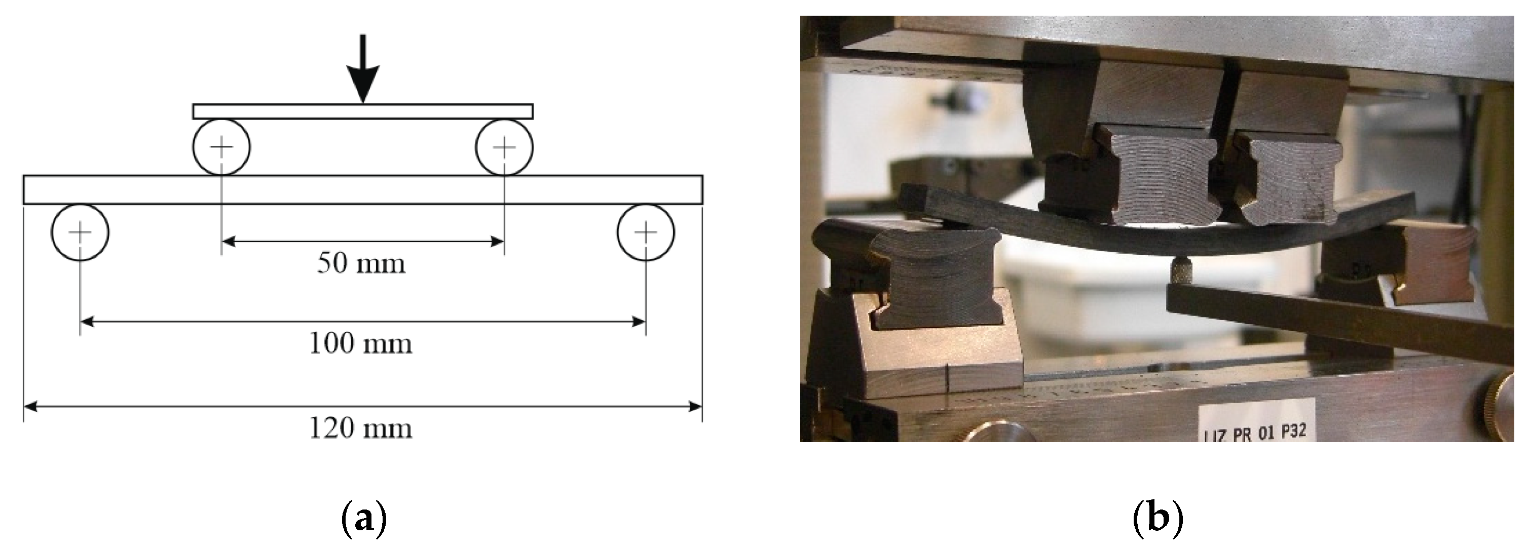
2.3. Experimental Setup and Measurement Techniques

Experimental mechanical tests were performed under four point bending in order to obtain both flexural strength and flexural stiffness. A Zwick/Roell 1475 universal testing machine with a 10 kN load cell was used for the experiments. Four-point bending tests were performed referring to standard DIN 53293 under quasi-static conditions with a testing velocity of 3.5 mm/s. The specimen was placed on two support elements with a radius of 2 mm and a distance of 100 mm between each other. The load was centrally applied via two loading elements with a radius of 2 mm and a distance of 50 mm between each other. The experimental setup of the four-point bending test is shown in Figure 3. The maximum deflection was measured at the centre on the underside of the specimen by a Zwick/Roell digital displacement transducer. Two specimens for each pin configuration were tested.

3. Experimental Results

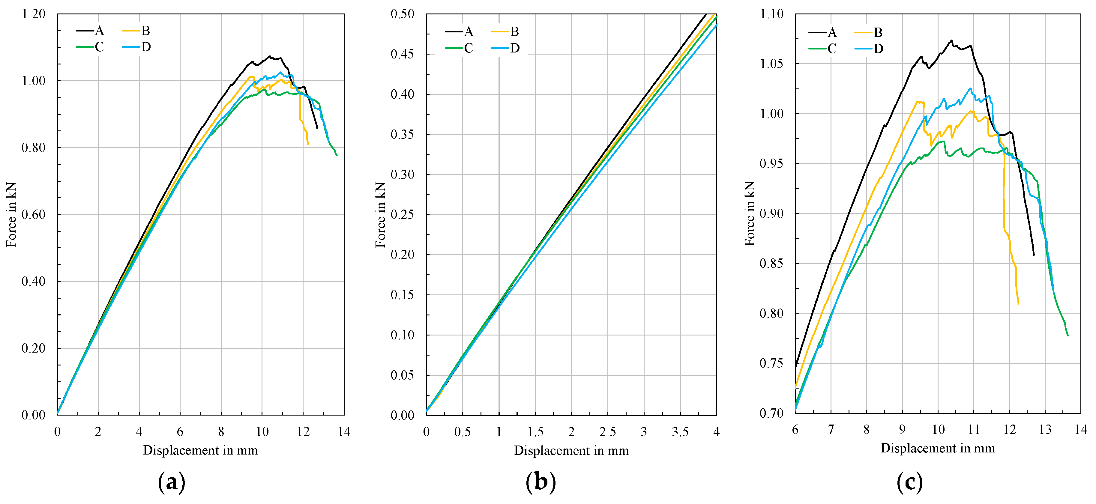
3.1. Force-Displacement Curves

The mean curves of the measured force-displacement behaviour for all tested specimens are shown in Figure 4. The behaviour is initially linear up to a displacement of about 2 mm. Afterwards, the behaviour is clearly non-linear and characterized by a decrease in stiffness until the maximum force is reached. The reduction in stiffness is related to the increase in pin content and is most significant for configuration D with a 1.18% pin volume content compared to configuration A (Figure 4b). As expected, the configuration A with the lowest pin volume content of 0.05% exhibits the highest maximum load. In case of a regular pin pattern as it is for configurations A, B and C where pins are located in the middle of the specimen, which is the area of the greatest bending load, the maximum load decreases as the pin volume content increases (Figure 4c). The specimens of configuration D, which exhibits a zigzag pin pattern, show a significantly lower decrease in stiffness and strength than configuration C with the same pin volume content of 1.18%. In contrast to configurations C, the zigzag pin pattern shows only one single pin in the area of the largest bending load, which in turn leads to a lower structural weakness in this area causing this effect.

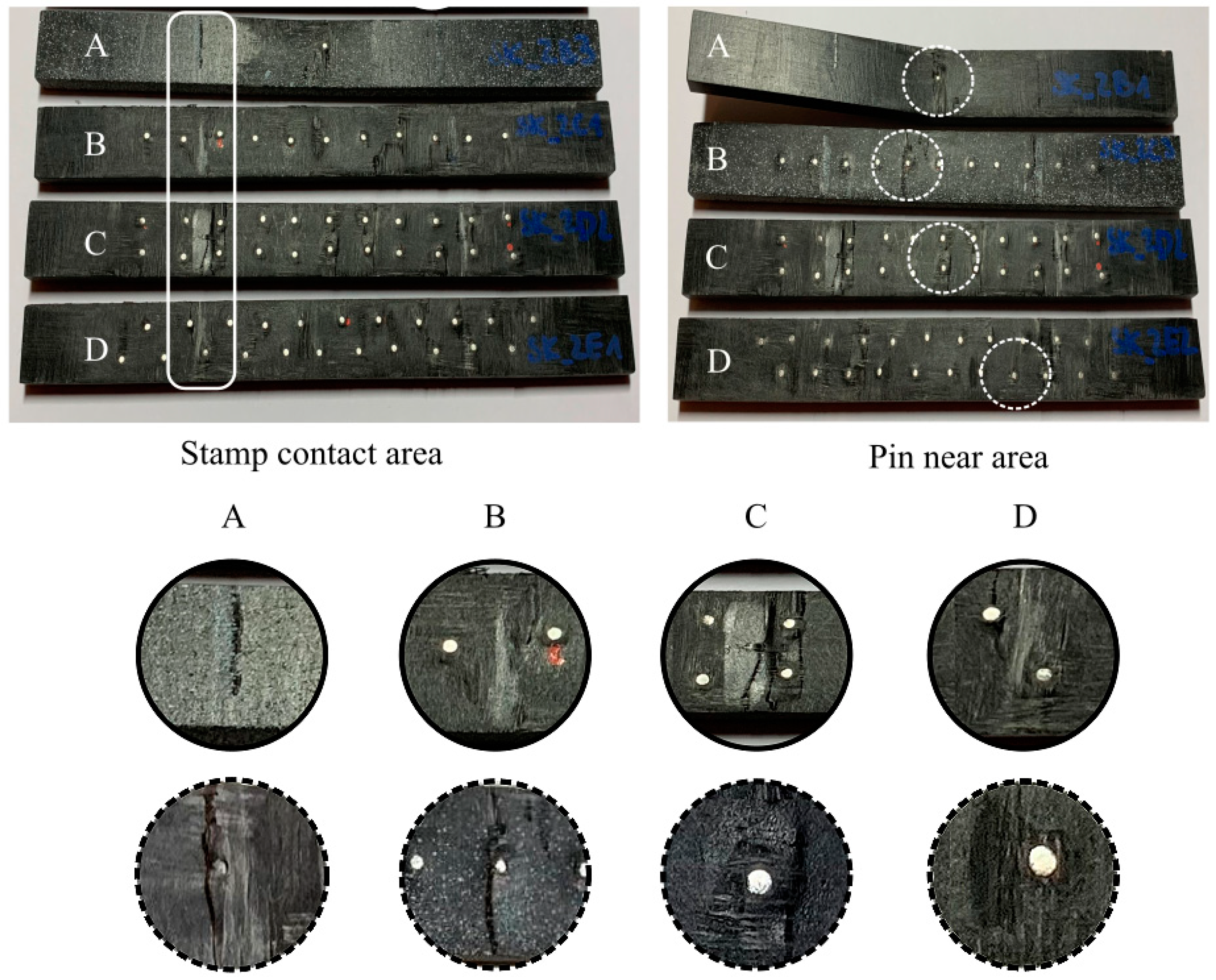
3.2. Failure Pattern

The identification and evaluation of the damage and failure patterns of the tested specimens are essential for the intended establishment of an appropriate simulation method of metallic pin reinforced thermoplastic composites. In Figure 5, selected specimens for each configuration after testing are shown. All specimens exhibit a compression damage on the upper specimen side in the contact area to the stamps. The specimens of configurations C and D show that if a pin is present in this area, such a localized loading causes the formation of a transverse cracks starting from the pins. Since all test specimens show this compression damage to the same extent, it is obvious that the initiation of such a damage is associated with the beginning of the non-linearity of all force-displacement curves. Subsequently, as force and displacement increase, the pins act as damage and crack initiators in the composite material. Figure 5 shows these cracks after testing in pin near areas. As to be expected, a crack formation occurs starting from the pins in the middle of the specimen for configurations A, B and C with regular pin pattern. For configuration D, which has no pin located in the area of largest bending load, no such crack occurs. A detachment of the pin from the composite specimen and the formation of a gap is hardly noticeable.

4. Numerical Analysis

4.1. Finite Element Model

In ABAQUS/Explicit, a finite element model was developed for the numerical analysis of the quasi-static four-point bending test of each pin configuration. The model, illustrated in Figure 6, contains the rectangular specimen, two rigid support and two loading elements corresponding to the experimental set-up. The support elements are fixed in all eligible degrees of freedom. The loading elements are subjected with a uniform motion according to the quasi-static conditions of the test. In order to enable reasonable computing times of the model for a time of 0.05 s, the time step was manually adjusted using certain mass scaling under the condition that the resulting kinetic energy is less than 10% of the total energy. The specimen and the pins are modelled by using eight-node continuum solid elements (C3D8R) with reduced integration. In order to ensure suitable finite element sizes, especially in the areas around the pin, sensitivity studies for four different mesh sizes were performed. Mesh sizes with in-plane element lengths of 0.8 mm, 0.3 mm, 0.15 mm and 0.08 mm were applied to predict accurately the stress concentration in the pin near area. The results show that the maximum in-plane stress begins to converge from a mesh size of 0.15 mm. The final chosen minimal element size of the pin is 0.08 mm × 0.08 mm × 0.32 mm. The element size of the composite specimen around the pins ranges from 0.15 mm × 0.14 mm × 0.625 mm in pin near area, up to 1.0 mm × 0.75 mm × 0.625 mm in edge area. It is assumed that due to the heat-treated manufacturing process a thin polypropylene layer without fibres exists around the pin. As the thermal conductivity of the polymer and glass are comparatively low, the size of the plasticized zone is limited to a few tenths of millimetres. The thickness of the layer is hard to measure as the molten zone decreases with rising penetration depth due to the pin cools down during insertion. For numerical reasons in regard of mesh density and contact stability, the mesh structure ensures a 0.3 mm layer of polypropylene, which is build up via two elements with a length of 0.15 mm. Debonding and subsequent slipping of the pin is realized using a cohesive contact formulation between pin and polypropylene layer. The damage and failure of the bond is modelled based on bi-linear elastic traction-separation law [34]. Due to the absence of the specific interface properties, the intralaminar properties of a comparable glass-polypropylene (GF/PP) hybrid yarn-based composite are used for the analysis (Table 1) [35]. The according friction behaviour after the pin is detached from the polypropylene layer is very demanding to characterize experimentally. It is largely dependent on the TAP process and its resulting local material structure. Coulomb friction, using a constant coefficient of 0.35, was used in the analysis, which is in the range for most polymers. It should be noted, that no extensive slipping of the pins occurred in the experiments so that the friction condition between pin and composite does not seem to be a governing factor.

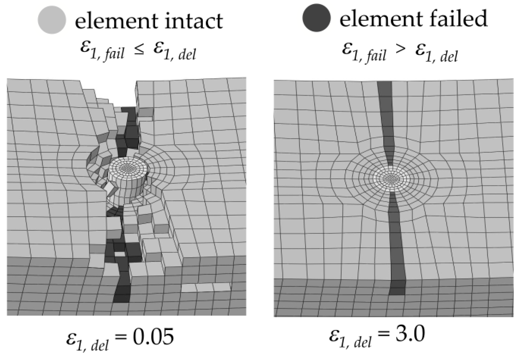
4.2. Material Modelling

A linear elastic material behaviour was assumed for the pin material with a Young’s modulus of 210 GPa and Poisson’s ratio of 0.3, same for the thin polypropylene layer around the pins by using a Young’s modulus of 1500 MPa and a Poisson’s ratio of 0.43 [36,37]. The composite CDM model is implemented in ABAQUS/Explicit as a user-defined subroutine VUMAT. This phenomenological material model enables the prediction of mode-related and direction-dependent failure based on the concept of Cuntze [26,29]. A successive stiffness degradation of the composite is achieved via an accumulative and mode related damage evolution. It is based on the assumption of linear-elastic material behaviour up to an initial damage threshold characterized by the damage strength Rdij t/c for each loading direction (i,j = 1, 2, 3), with t denoting tension and c compression. The damage surface in stress space using a variable function H is described by the following condition by means of nominal stresses σi and τij:
H n = ( σ 1 + R d 1 t ) n + ( σ 1 R d 1 c ) n + ( σ 2 + R d 2 t ) n + ( σ 2 R d 2 c ) n + ( σ 3 + R d 3 t ) n + ( σ 3 R d 3 c ) n + ( τ 12 R d 12 ) n + ( τ 31 R d 31 ) n + ( τ 23 R d 23 ) n = 1 .
The rounding-off coefficient n defines the failure envelope. In this study, n was fixed to a value of 2. A pragmatic non-interactive strain based failure conditions F for tension, compression and shear loading with the failure threshold εit/c,fail and γij,fail were used:
F t , c = ( ε i ε i t / c f a i l ) = 1   and   F s = ( γ i j γ i j , f a i l ) = 1 .
Here, after fracture is predicted, only for tensile failure mode the failed element is deleted. As load can still be transmitted, a residual strength for compressive mode and shear mode is retained until a deletion strain εi,del and γij,del is reached and the element is finally deleted. The required material parameters result from previous experimental works by means of basic characterization tests under tensile, compression and shear loading [3,38,39,40]. For simplification, the layup of the specimens with consistent hybrid yarns in both reinforcement direction, the balanced textile architecture and the symmetric lay-up result in a bidirectional layer with almost same in-plane engineering constants. Via the experimental determined parameters and corresponding stress-strain-relationship, the material input parameter for the CZM model were determined by single-element-tests. The engineering constants (Young’s moduli Ei, shear moduli Gij and Poisson’s ratios vij), onset of damage in terms of strengths Rdij t/c, and failure strains εit/c,fail and γij,fail for the GF/PP composite material for each loading direction (i,j = 1, 2, 3) are listed in Table 2.
Within this study, the determination and calibration of the required eroding strain and residual strength parameter (Rd for compression and Rs for shear loading) for the post-failure behaviour was carried out based on specimens with a single pin reinforcement (configuration A) in regard to its failure pattern and force-displacement behaviour. The final parameters for element deletion are listed in Table 3. The relevance of these non-physical parameter for the global failure pattern accompanied by the global structural response is shown in Figure 7. Especially, the element deletion in the contact area below the stamps was addressed here.

4.3. Results and Discussion

Figure 8 compares the calculated and measured force-displacement curves for the pinned specimen and shows a good agreement of the successive stiffness degradation for all pin configuration. It can be assumed that the pin, with the densities considered in this study, only change a little or not at all the flexural stiffness at the beginning. This is changing as the load increases, with the pins acting as crack initiators and thus earlier or later can be responsible for a subsequent stiffness degradation (Figure 8b). This assumption is confirmed by the results of the configuration A, with only one single pin, indicating a much less stiffness degradation than the other configurations with at least seven pins in the bending area. The maximum force and its associated displacement for the configuration A agrees well with the experimental data (Figure 8c). For configurations B, C and D there exist small deviations in force and timing. This agreement and these differences probably result from the cohesive properties of the interface between pin and composite which were assumed according to the intralaminar properties of the composite. With regard to the effect of the TTR, a further characterization of the pin-composite interface is essential, especially if extended pin slipping until a pin pullout occurs.
The calculated damage and failure pattern correspond well with the observed phenomena in the experiments. The damage onset, first element failure and final failure pattern for configuration are illustrated in Figure 9. It is shown that the damage onset starts in from the pins, which are located in the area of the largest bending stress. As the load increases, a crack propagates to the edge of the specimen. Such material damage and failure states are visualized via predefined user-defined state variables, here, e.g., the material failure in longitudinal direction of the test specimen. At the same time, further damage and cracks are initiated from the remaining pins. This is accompanied with the compression failure on the upper side of the specimen in the contact area to the stamp elements. The configurations A, B and C with a regular pin pattern show an earlier damage and failure initiation with increasing pin density. This clearly shows that the pin density and the corresponding strengthening effect of the TTR are limited by the accompanying weakening of the in-plane material properties. The zigzag pin pattern shows a delay both in damage onset and failure in comparison with the regular pin pattern. Due to the unregular pin pattern of configuration D regarding to the direction of the main load, the linkage of cracks initiated at the pins is not possible. Thus, a load or damage and failure adapted positioning of the pin pattern enables a more extensive exploitation of the TTR potential.

5. Conclusions

In this study, the four-point bending behaviour of through-thickness metallic pin reinforced glass-fibre/thermoplastic composite is experimentally characterized and numerical modelled. Hereby, four pin configurations with various pin density and pattern were in focus of the research and realized by the novel thermoactivated pinning technology. A validated finite element model has been developed which enables the analysis of the flexural behaviour, damage and failure behaviour of pin reinforced thermoplastic composites. With the presented model, using a phenomenological material model for the composite material, the damage onset and propagation up to the final failure are shown. A surface-based cohesive zone behaviour were applied to the interface between pin and composite to handle debonding and possible slipping of the pin. The modelling approach was able to predict well the force-displacement curve and the successive stiffness degradation of the specimens due to the pin reinforcement. The damage and failure pattern corresponds well with the experimental data observed. It has been shown that the pins act as crack initiators and this essentially affect the flexural and in-plane properties of the reinforced composite. With increasing pin density, the damage onset and initial failure starts earlier for specimens with a regular pin pattern. This limits the number of pins used by weakening the in-plane properties of the composite. However, an unregular zigzag pin pattern compared to a regular pattern with same pin density shows a delayed damage onset. The damage onset can thus be reduced by a damage and failure adapted pin pattern.

Author Contributions

Conceptualization, H.B. and B.G.; methodology, H.Z. and H.B.; software, H.Z.; validation, H.Z.; formal analysis, H.Z.; investigation, H.Z.; resources, H.B. and B.G.; data curation, H.B.; writing—original draft preparation, H.B., H.Z. and B.G.; writing—review and editing, H.B., A.H. and M.G.; visualization, H.B.; supervision, A.H. and M.G.; project administration, A.H. and M.G.; funding acquisition, M.G. All authors have read and agreed to the published version of the manuscript.

Funding

This research was funded by the German Research Foundation (DFG) within the project Transregional Collaborative Research Centre 285 (TRR 285) (project number 418701707) sub-project A03.

Acknowledgments

The authors would like to thank Stefan Kahlenberg, who contributed significantly to the experimental work, in particular to the manufacturing of the test specimens within the scope of his student work. Furthermore, we would like to thank Hailun Zhang for his active support of the numerical work during his diploma thesis.

Conflicts of Interest

The authors declare no conflict of interest.

References

  1. Bourban, P.E.; Bögli, A.; Bonjour, F.; Månson, J.A. Integrated processing of thermoplastic composites. Compos. Sci. Technol. 1998, 58, 633–637. [Google Scholar] [CrossRef]
  2. Vaidya, U.K.; Chawla, K.K. Processing of fibre reinforced thermoplastic composites. Int. Mater. Rev. 2008, 53, 185–218. [Google Scholar] [CrossRef]
  3. Hufenbach, W.; Böhm, R.; Thieme, M.; Winkler, A.; Mäder, E.; Rausch, J.; Schade, M. Polypropylene/glass fibre 3D-textile reinforced composites for automotive applications. Mater. Des. 2011, 32, 1468–1476. [Google Scholar] [CrossRef]
  4. Budhe, S.; Banea, M.D.; De Barros, S.; Da Silva, L.F.M. An updated review of adhesively bonded joints in composite materials. Int. J. Adhes. Adhes. 2017, 72, 30–42. [Google Scholar] [CrossRef]
  5. Yousefpour, A.; Hojjati, M.; Immarigeon, J.P. Immarigeon: Fusion Bonding/Welding of Thermoplastic Composites. J. Thermoplast. Compos. Mater. 2004, 17, 303–341. [Google Scholar] [CrossRef]
  6. Galińska, A.; Galiński, C. Mechanical Joining of Fibre Reinforced Polymer Composites to Metals—A Review. Part II: Riveting, Clinching, Non-Adhesive Form Locked Joints, Pin and Loop Joining. Polymers 2020, 12, 1681. [Google Scholar] [CrossRef]
  7. Seidlitz, H.; Kuke, F.; Tsombanis, N. Advanced joining technology for the production of highly stressable lightweight structures, with fiber-reinforced plastics and metals. Technol. Lightweight Struct. 2017, 1, 54–67. [Google Scholar] [CrossRef]
  8. Hufenbach, W.; Kupfer, R.; Hornig, A. Thermoactivated Pinning—A novel joining technique for thermoplastic composites. In Solid State Phenomena; Trans Tech Publications Ltd.: Bäch, Switzerland, 2012; Volume 188, pp. 176–181. [Google Scholar] [CrossRef]
  9. Parkes, P.N.; Butler, R.; Meyer, J.; De Oliveira, A. Static strength of metal-composite joints with penetrative reinforcement. Compos. Struct. 2014, 118, 250–256. [Google Scholar] [CrossRef] [Green Version]
  10. Wisnom, M.R. The role of delamination in failure of fibre-reinforced composites. Philos. Trans. R. Soc. 2012, 370, 1850–1870. [Google Scholar] [CrossRef]
  11. Gnaba, I.; Legrand, X.; Wang, P.; Soulat, D. Through-the-thickness reinforcement for composite structures: A review. J. Ind. Text. 2019, 49, 71–96. [Google Scholar] [CrossRef]
  12. Mouritz, A.P. Mechanics of 3D fibre reinforced polymer composites. In Encyclopedia of Continuum Mechanics; Altenbach, H., Öchsner, A., Eds.; Springer: Berlin/Heidelberg, Germany, 2019. [Google Scholar] [CrossRef]
  13. Kostopoulos, V.; Sarantinos, N.; Tsantzalis, S. Review of Through-the-Thickness Reinforced z-Pinned Composites. J. Compos. Sci. 2020, 4, 31. [Google Scholar] [CrossRef] [Green Version]
  14. Pingkarawat, K.; Mouritz, A.P. Comparative study of metal and composite z-pins for delamination fracture and fatigue strengthening of composites. Eng. Fract. Mech. 2016, 154, 180–190. [Google Scholar] [CrossRef]
  15. Cartié, D.D.; Cox, B.N.; Fleck, N.A. Mechanics of crack bridging by composite and metallic rods. Compos. Part A Appl. Sci. Manuf. 2004, 35, 1325–1336. [Google Scholar] [CrossRef] [Green Version]
  16. Son, J.H.; Chun, H.J.; Kang, K.T.; Lee, H.Y.; Byun, J.H.; Um, M.K.; Kim, B.S. Effect of Z-Pin on the through-the-Thickness Strength of Woven Composite Laminates. In Advanced Materials Research; Trans Tech Publications Ltd.: Bäch, Switzerland, 2010; Volume 123, pp. 47–50. [Google Scholar] [CrossRef]
  17. M’membe, B.; Gannon, S.; Yasaee, M.; Hallett, S.R.; Partridge, I.K. Mode II delamination resistance of composites reinforced with inclined z-pins. Mater. Des. 2016, 94, 565–572. [Google Scholar] [CrossRef] [Green Version]
  18. M’membe, B.; Yasaee, M.; Hallett, S.R.; Partridge, I.K. Effective use of metallic z-pins for composites’ through-thickness reinforcement. Compos. Sci. Technol. 2019, 175, 77–84. [Google Scholar] [CrossRef] [Green Version]
  19. Pegorin, F.; Pingkarawat, K.; Daynes, S.; Mouritz, A.P. Mode II interlaminar fatigue properties of z-pinned carbon fibre reinforced epoxy composites. Compos. Part A Appl. Sci. Manuf. 2014, 67, 8–15. [Google Scholar] [CrossRef]
  20. Wang, S.; Zhang, Y.; Sun, P.; Cui, Y.; Wu, G. Microstructure and Flexural Properties of Z-pinned Carbon Fiber-Reinforced Aluminum Matrix composites. Materials 2019, 12, 174. [Google Scholar] [CrossRef] [Green Version]
  21. Bisagni, C.; Furfari, D.; Pacchione, M. Experimental investigation of reinforced bonded joints for composite laminates. J. Compos. Mater. 2018, 52, 431–447. [Google Scholar] [CrossRef] [Green Version]
  22. Chun, H.J.; Son, J.; Kang, K.T.; Byun, J.H.; Um, M.K.; Lee, S.K. Prediction of elastic properties for woven z-pinned composites. Compos. Part B Eng. 2014, 64, 59–71. [Google Scholar] [CrossRef]
  23. Grassi, M.; Zhang, X.; Meo, M. Prediction of stiffness and stresses in z-fibre reinforced composite laminates. Compos. Part A Appl. Sci. Manuf. 2002, 33, 1653–1664. [Google Scholar] [CrossRef] [Green Version]
  24. Chang, P.; Mouritz, A.P.; Cox, B.N. Flexural properties of z-pinned laminates. Compos. Part A Appl. Sci. Manuf. 2007, 38, 244–251. [Google Scholar] [CrossRef]
  25. Chang, P.; Mouritz, A.P.; Cox, B.N. Properties and failure mechanisms of z-pinned laminates in monotonic and cyclic tension. Compos. Part A Appl. Sci. Manuf. 2006, 37, 1501–1513. [Google Scholar] [CrossRef]
  26. Pinho, S.T.; Iannucci, L.; Robinson, P. Physically-based failure models and criteria for laminated fibre-reinforced composites with emphasis on fibre kinking: Part I: Development. Compos. Part A Appl. Sci. Manuf. 2006, 37, 63–73. [Google Scholar] [CrossRef] [Green Version]
  27. Matzenmiller, A.L.J.T.R.; Lubliner, J.; Taylor, R.L. A constitutive model for anisotropic damage in fiber-composites. Mech. Mater. 1995, 20, 125–152. [Google Scholar] [CrossRef]
  28. Böhm, R.; Gude, M.; Hufenbach, W. A phenomenologically based damage model for textile composites with crimped reinforcement. Compos. Sci. Technol. 2010, 70, 81–87. [Google Scholar] [CrossRef]
  29. Cuntze, R.G. Strength failure conditions of various structural materials: Is there some common basis existing. Sdhm Struct. Durab. Health Monit. 2007, 3, 87–105. [Google Scholar]
  30. Böhm, H.; Weck, D.; Hornig, A.; Langkamp, A.; Adam, F.; Gude, M. Experimental and numerical study on the axial crushing behavior of textile-reinforced thermoplastic composite tubes. Adv. Eng. Mater. 2016, 18, 437–443. [Google Scholar] [CrossRef]
  31. Zhang, B.; Allegri, G.; Yasaee, M.; Hallett, S.R. Micro-mechanical finite element analysis of z-pins under mixed-mode loading. Compos. Part A Appl. Sci. Manuf. 2015, 78, 424–435. [Google Scholar] [CrossRef]
  32. Bianchi, F.; Koh, T.M.; Zhang, X.; Partridge, I.K.; Mouritz, A.P. Finite element modelling of z-pinned composite T-joints. Compos. Sci. Technol. 2012, 73, 48–56. [Google Scholar] [CrossRef]
  33. Taotao, Z.; Wenbo, L.; Wei, X.; Ying, Y. Numerical simulation of single-lap adhesive joint of composite laminates. J. Reinf. Plast. Compos. 2018, 37, 520–532. [Google Scholar] [CrossRef]
  34. ABAQUS, Version 6.7; Analysis User’s Manual; Dassault Systemes Simulia, Inc.: Waltham, MA, USA, 2017.
  35. Kuhtz, M.; Hornig, A.; Gude, M.; Jäger, H. A method to control delaminations in composites for adjusted energy dissipation characteristics. Mater. Des. 2017, 123, 103–111. [Google Scholar] [CrossRef]
  36. DIN EN 1993-1-8:2010-12: Eurocode 3: Design of Steel Structures—Part 1-1: General Rules and Rules for Buildings; German Version EN 1993-1-1:2005 + AC: 2009, Standard. 2010. Available online: https://www.beuth.de/de/norm/din-en-1993-1-8/134178148 (accessed on 16 November 2020). [CrossRef]
  37. Polymerdatabase.com Polypropylene. In Polymer Properties Database. 2020. Available online: https://polymerdatabase.com/Commercial%20Polymers/PP.html (accessed on 5 May 2020).
  38. Böhm, R.; Hufenbach, W. Experimentally based strategy for damage analysis of textile-reinforced composites under static loading. Compos. Sci. Technol. 2010, 70, 1330–1337. [Google Scholar] [CrossRef] [Green Version]
  39. Hufenbach, W.; Langkamp, A.; Hornig, A.; Ebert, C. Experimental determination of the strain rate dependent out-of-plane properties of textile reinforced composites. In Proceedings of the 17th International Conference on Composite Materials (ICCM 17), Edinburgh, UK, 27–31 July 2009. [Google Scholar]
  40. Brown, K.A.; Brooks, R.; Warrior, N.A. The static and high strain rate behavior of a commingled E-glass/polypropylene woven fabric composite. Compos. Sci. Technol. 2010, 70, 272–283. [Google Scholar] [CrossRef]
Figure 1. Woven fabric material: (a) before consolidation; (b) after consolidation.
Jcs 04 00188 g001
Figure 2. Specimen configuration: (A) 0.05% pin density; (B) 0.59% pin density; (C) regular pattern with 1.18% pin density; (D) zigzag pattern with 1.18% pin density.
Jcs 04 00188 g002
Figure 3. Four-point bending test setup: (a) schematic picture; (b) self-build setup.
Jcs 04 00188 g003
Figure 4. Comparison of experimental force-displacement curves: (a) entire results; (b) detailed elastic domain; (c) detailed damage and failure domain.
Jcs 04 00188 g004
Figure 5. Characteristic damage and failure pattern for each configuration: (A) 0.05% pin density; (B) 0.59% pin density; (C) regular pattern with 1.18% pin density; (D) zigzag pattern with 1.18% pin density.
Jcs 04 00188 g005
Figure 6. Finite element model of four point bending test (configuration D).
Jcs 04 00188 g006
Figure 7. Adjustment of the post-failure behaviour via element deletion strain parameter.
Jcs 04 00188 g007
Figure 8. Comparison of experimental and numerical force-displacement curves: (a) entire results; (b) detailed elastic domain; (c) detailed damage and failure domain.
Jcs 04 00188 g008
Figure 9. Damage onset and failure pattern.
Jcs 04 00188 g009
Table 1. Parameter of cohesive zone model for interface between pin and composite.
Initial   Stiffness   M (N/mm) Cohesive   Strength   t (MPa) Critical   Strain   Energy   Release   Rate   G (N/mm)
M n n 74,670 t n 0 12.6 G I C 2.5
M s s 26,670 t s 0 92.0 G I I C 3.5
M t t 26,670 t t 0 92.0 G I I I C 3.5
Table 2. Engineering constants, onset of damage in terms of strengths and failure strains for glass-polypropylene (GF/PP) composite material.
Material ParameterUnitValue
E1(GPa)14.9
E2(GPa)14.9
E3(GPa)1.50
ν12(-)0.08
ν13(-)0.17
ν23(-)0.17
G12(MPa)7500
G13(MPa)1050
G23(MPa)1050
Rd1t(MPa)60
Rd1c(MPa)35
Rd2t(MPa)60
Rd2c(MPa)35
Rd3t(MPa)12.4
Rd3c(MPa)477
Rd12(MPa)25
Rd13(MPa)9
Rd23(MPa)9
ε1t, fail(-)0.1
ε1c, fail(-)0.03
ε2t, fail(-)0.1
ε2c, fail(-)0.03
ε3t, fail(-)0.2
ε3c, fail(-)0.08
γ12, fail(-)0.016
γ13, fail(-)0.014
γ23, fail(-)0.014
Table 3. Element eroding strains and scale factor for minimum stress limit after stress maximum for GF/PP composite material.
Material ParameterUnitValue
ε1, del(-)3.0
ε2, del(-)3.0
γ12, del(-)0.15
Rc(MPa)0.5
Rs(MPa)1.0
Publisher’s Note: MDPI stays neutral with regard to jurisdictional claims in published maps and institutional affiliations.

