Article

Multiscale Analysis of Elastic Properties of Nano-Reinforced Materials Exhibiting Surface Effects. Application for Determination of Effective Shear Modulus

Laboratoire Modélisation et Simulation Multi Echelle, Université Paris-Est, MSME UMR 8208 CNRS, 5 bd Descartes, 77454 Marne-la-Vallée, France
J. Compos. Sci. 2020, 4(4), 172; https://doi.org/10.3390/jcs4040172
Submission received: 24 September 2020 / Revised: 27 October 2020 / Accepted: 19 November 2020 / Published: 21 November 2020
(This article belongs to the Special Issue Multiscale Analysis of Polymer Nanocomposites)

Abstract

:
This work concerns a multiscale analysis of nano-reinforced heterogeneous materials. Such materials exhibit surface effects that must be taken into account in the homogenization procedure. In this study, a coherent imperfect interface model was employed to characterize the jumps of mechanical properties through the interface region between the matrix and the nanofillers. As the hypothesis of scale separation was adopted, a generalized self-consistent micromechanical scheme was employed for the determination of the homogenized elastic moduli. An explicit calculation for the determination of effective shear modulus is presented, together with a numerical application illustrating the surface effect. It is shown that the coherent imperfect interface model is capable of exploring the surface effect in nano-reinforced materials, as demonstrated experimentally in the literature.

1. Introduction

Composite or composite material consists of at least two elementary phases [1,2,3,4]. This is an artificial assembly, achieved by exploiting the capacity of adhesion between the constituents—namely the matrix and the reinforcements. The composite (or the reinforced matrix) exhibits many mechanical, thermal, and electrical properties, which are beneficial in comparison to those of the pure matrix. Thanks to these various reinforcements, composites are increasingly being used in industry. When one, two or three of the dimensions of the reinforcement are less than 100 nanometers, the resulting material is called a nanocomposite [5,6,7]. Nanocomposites are a novel field of industrial research. Because of the nanometric dimensions of the reinforcement, nanocomposites are highly complex to manufacture, and therefore also to model mechanically. Polymer-based nanocomposites are very frequently used in industry due to the relative ease with which they can be produced using several manufacturing methods, and also the low cost of this type of material. For example, nanocomposites based on thermoplastic polyolefin are commonly used for manufacturing in the automotive industry [8,9]. In this study, we focus on nanocomposites with a polymer matrix reinforced by nanoparticles.
Perhaps the most widely discussed aspect of nanocomposites is the existence of a disturbed region of the matrix surrounding the nanoinclusions, called the interface region, due to the nature of adhesion between the elementary phases in the nanocomposite. This observation has been made in the literature in a range of experimental [10,11] and numerical [12,13] works. At very small scales (in this instance, nanometric), atomic bonds become the characteristics used to describe interactions between the nanofillers and the matrix, or between different nanofiller particles. Thus, multiscale modeling of such a material must take these atomic characteristics into account. A difficulty often encountered in modeling such a material is that the macroscopic properties are highly dependent on the coupling between several parameters, such as the size effect or the aggregation of reinforcements [14].
Modeling of the interface region is crucially important to predict the effective properties of the heterogeneous materials [15,16]. From a general standpoint, the interface region is of non-zero volume fraction in the material, and contains different mechanical properties with the matrix and the inclusion (see [17,18]). Therefore, in general, its thickness may be constant or fluctuating, and its mechanical properties may be homogeneous or non-homogeneous [19,20,21,22,23,24]. In the literature, for approximation of the effective properties of materials with an interface region, there are two main categories of approaches to simulate this region. The first is to approach the effective properties using interface models, where we assume that the interface region is zero volume fraction in the material. The basic idea in constructing interface models is to replace the interface region with an interface of zero thickness (i.e., zero volume fraction) by stipulating that the jumps of physical and mechanical properties through this interface be almost equal to the jumps of those same properties through the interface region, with a fixed error (see [17,18,25,26,27,28]). In this work, we are interested in the jumps of mechanical properties (i.e., displacement, strain and stress fields, respectively), also known as discontinuities (see [29]).
This study is devoted to a multiscale analysis of the elastic properties of particulate nanocomposites presenting surface effects, together with an application for the determination of effective shear modulus. The paper is organized as follows. Section 2 is devoted to the modeling of the mechanical properties of the interface region using an interface model. The micromechanical homogenization scheme of nano-reinforced materials is introduced in Section 3. Section 4 is given over to explicit calculation for the determination of the effective shear modulus. Finally, Section 5 presents the numerical application, showing surface effects in nano-reinforced materials through the interface model.

2. Imperfect Interface Model

2.1. Geometric Description of Interface

We use the term interface to denote a surface (or a transition zone) separating two bodies or two parts of a body. In order to describe the topology of the interface denoted by Γ , we consider a solid Ω R 3 made up of two materials (obeying any behavior laws), respectively occupying the subdomains Ω ( 1 ) and Ω ( 2 ) , assumed to be separated by the interface Γ such that (see Figure 1),
Ω = Ω ( 1 ) Ω ( 2 ) ,
Γ = Ω ( 1 ) Ω ( 2 ) .
Mathematically, the interface Γ can be defined by the following level-set function f : R 3 R such that
Γ = x R 3 | f ( x ) = 0 ,
where the function f is classically assumed to be twice differentiable. The unit vector normal to Γ at point x , denoted by n ( x ) , is then defined by
n ( x ) = f ( x ) f ( x ) ,
with f ( x ) 0 , x Γ .

2.2. Perfect Elastic Interface

In the case of so-called perfect interfaces, the displacement field and stress vector are assumed to be continuous at the interface (see [26,30,31]). We can specify the displacement field u ( x ) and stress field σ ( x ) of the domain Ω by introducing
u ( x ) = u ( 1 ) ( x ) si x Ω ( 1 ) u ( 2 ) ( x ) si x Ω ( 2 )
and
σ ( x ) = σ ( 1 ) ( x ) si x Ω ( 1 ) σ ( 2 ) ( x ) si x Ω ( 2 )
We then write the continuity hypotheses for the point x Γ
  • Continuity of the displacement field
    u ( x ) = u ( 2 ) ( x ) u ( 1 ) ( x ) = 0 .
  • Continuity of the stress vector
    σ ( x ) n ( x ) = σ ( 2 ) ( x ) σ ( 1 ) ( x ) n ( x ) = 0 .
By applying Hadamard’s relation for a vector function (see [26]), we obtain the jump of the displacement gradient at the interface
u ( x ) = u ( 2 ) ( x ) u ( 1 ) ( x ) = α n ( x ) ,
and using the mechanical relation ε = 1 2 ( u + u T ) , we then deduce the jump of the strain field at the interface Γ
ε = ε ( 2 ) ε ( 1 ) = 1 2 u ( 2 ) + u ( 2 ) T 1 2 u ( 1 ) ) + u ( 1 ) T = 1 2 u ( 2 ) u ( 1 ) + 1 2 u ( 2 ) T u ( 1 ) T = 1 2 ( α n + n α )
We introduce the surface strain tensor ε s by
ε s = 𝕥 ε 𝕥 ,
then we calculate the jump ε s at the interface Γ
ε s = 𝕥 ε 𝕥 = 𝕥 ε ( 2 ) 𝕥 𝕥 ε ( 1 ) 𝕥 = 𝕥 ( ε ( 2 ) ε ( 1 ) ) 𝕥 ,
and by introducing the result of Equation (10), we obtain
ε s = 1 2 𝕥 ( α n + n α ) 𝕥 = 1 2 ( 𝕥 α ) ( 𝕥 T 𝕟 ) + ( 𝕥 𝕟 ) ( 𝕥 T α ) = 0 ,
where the tensorial relation A ( a b ) A = ( A a ) ( A T b ) , with A being a second-order tensor and a and b being two vectors, is introduced in Gu [30], we then find that ε s = 0 , using the property of two second-order projection operators, 𝕥 T = 𝕥 , and 𝕥 𝕟 = 0 (see [30]). This result shows that the surface strains are continuous across the interface Γ . We introduce the following tensorial relation
𝕥 ε 𝕥 = ( 𝕥 ̲ ¯ 𝕥 ) : ε = P : ε ,
where P is the operator defined by Equation (A4). We can then rewrite the result of Equation (13)
ε s = 𝕥 ε ( 2 ) 𝕥 𝕥 ε ( 1 ) 𝕥 = P : ε ( 2 ) P : ε ( 1 ) = P : ε = 0 ,
This is the first relation of continuity at the interface Γ for the strain field.
Then, the continuity of the stress vector implies that
P : σ ( 2 ) P : σ ( 1 ) = 0 ,
where P is the operator defined by Equation (A5). Finally, the relationships of continuity across the perfect interface Γ are
P : ε = 0 ,
P : σ = 0 .
More information on projection operators and elastic moduli can be found in Appendix A and Appendix B.

2.3. Imperfect Elastic Interface

In several situations, the perfect interface hypothesis is no longer adopted (see [26]). The most important reason is that the energy of the interface is not negligible compared to the energy of the domain (see [31]). Because of this phenomenon, there is a major increase in effective properties. In this section, in the wake of the previous section’s presentation of the problem of the surface elasticity so that the jumps of mechanical values through the interface are almost equal to the jumps of the same values through the interface region, we present a general and systematic approach based on asymptotic analysis to establish imperfect interface models (see [29,30]).
Figure 2a shows a simple depiction of the three-phase configuration, the interface region of thickness t ( x ) , occupying the domain Ω ( 0 ) , separating the two sub-domains Ω ( 1 ) and Ω ( 2 ) (see [30]). The basic idea to construct an interface model is to replace the area of Ω ( 0 ) in the three-phase configuration with an interface Γ of zero thickness in the two-phase configuration by stipulating that the jumps of mechanical properties through the interface Γ are almost equal to the jumps of the same properties through the surface Γ 1 and Γ 2 , with a fixed error (see [26]). Γ is called an imperfect interface. The two-phase configuration is represented by Figure 2b, where at the interface Γ , there are discontinuities of displacement, strain and stress fields. These discontinuities are called interface conditions (see [17]); they are added to the classical homogenization equations to solve the problem of heterogeneous material with imperfect interfaces.
In the literature, there are several types of imperfect interface models, such as the imperfect linear spring interface (see [28]), and coherent imperfect interface (see [17,18,26,31]). These two types are classified essentially by discontinuities of mechanical fields across the imperfect interface. We would like to focus here on the coherent imperfect interface model. To describe the mechanical properties through the coherent imperfect interface, we consider a domain of heterogeneous material having a coherent elastic interface between the matrix and the inclusion. We then introduce the displacement fields u s , strain ε s , and stress σ s of the coherent interface. Mechanical properties across the coherent imperfect interface Γ are represented below, using the terminology introduced in [17,18,31].
  • Continuity of the displacement field
    u = u ( 2 ) u ( 1 ) = 0 .
    Similarly, when the displacement field is continuous at the interface, we obtain the continuity relationship of surface deformation at the interface using Equation (17)
    P : ε = 0 .
  • Discontinuity of the stress vector (see [31])
    σ n = σ ( 2 ) n σ ( 1 ) n = div s ( σ s ) ,
    with div s being the surface divergence operator, and σ s the stress tensor of the interface. The stress vector is no longer continuous at the interface. The following relation represents this discontinuity (see Equation (18))
    P : σ = div s ( σ s ) .
These relations are used in the same way as the interface conditions in the section discussing the homogenization scheme.

3. Homogenization of Heterogeneous Materials Presenting an Interface

It is assumed that there is a separation of scale, such that the homogenization operator becomes deterministic. Therefore, a classical (pseudo-) analytical (see [31]) or numerical (see [32]) model could be used to homogenize the microstructure with an imperfect interface. In this work, a pseudo-analytical estimation system was applied to solve the homogenization problem.

3.1. Description of Microstructure

The microstructure in question is presented in Figure 3. Each phase—the inclusion (denoted by i), the matrix (denoted by m), and the interface (denoted by s)—is composed of linear, homogeneous and isotropic material. The elastic constants of the inclusion, the matrix and the interface are denoted by ( κ i , μ i ), ( κ m , μ m ), and ( κ s , μ s ), respectively. In this study, the inclusion occupies the volume of radius r 1 and the matrix occupies the volume, the radius of which ranges from r 1 to r 2 .
The constitutive laws of the matrix and inclusion are represented by the following equations
σ m = 𝕔 m : ε m ,
σ i = 𝕔 i : ε i ,
where in the isotropic case, the elasticity tensor 𝕔 m or 𝕔 i could be specified:
𝕔 p = κ p + 4 μ p / 3 κ p 2 μ p / 3 κ p 2 μ p / 3 0 0 0 κ p 2 μ p / 3 κ p + 4 μ p / 3 κ p 2 μ p / 3 0 0 0 κ p 2 μ p / 3 κ p 2 μ p / 3 κ p + 4 μ p / 3 0 0 0 0 0 0 2 μ p 0 0 0 0 0 0 2 μ p 0 0 0 0 0 0 2 μ p ,
with p = m ( m a t r i x ) or p = i ( i n c l u s i o n ) .

3.2. Interface Condition

The elasticity model of the interface is characterized by the following equation
σ s = 𝕔 s : ε s ,
where in the isotropic case, the elastic constants of the interface are such that ( λ s , μ s ), the constitutive law is written as follows (see [18])
σ s = λ s tr ( ε s ) 1 + 2 μ s ε s ,
where 1 is the identity tensor in two-dimensional space. We represent the constitutive law in a matrix form as follows (see [31])
σ θ θ s σ φ φ s σ θ φ s = κ s + μ s κ s μ s 0 κ s μ s κ s + μ s 0 0 0 2 μ s ε θ θ s ε φ φ s ε θ φ s ,
with the relationship κ s = 2 ( λ s + μ s ) (see [17]). We subsequently detail the discontinuity of the stress vector at the interface represented by Equation (21). We introduce the result of Povstenko’s work (see [33]). By studying the balance of the interface Γ , we obtain the explicit form of the discontinuity (see [17,31] for more details):
σ r r e r + σ r θ e θ + σ r φ e φ = div s σ s ,
where the surface divergence operator div s is calculated in spherical coordinates by the following formula (see [26])
div s σ s = σ θ θ s + σ φ φ s e r r + e θ r σ θ θ s θ + 1 sin θ σ θ φ s φ + σ θ θ s σ φ φ s cot θ + e φ r σ θ φ s θ + 1 sin θ σ φ φ s φ + 2 σ θ φ s cot θ .
This interface condition is added to the classical homogenization equations in the following sections.

3.3. Generalized Self-Consistent Scheme

We propose, in this work, to use the generalized self-consistent scheme to solve the homogenization problem. This scheme is detailed explicitly in the work of Christensen and Lo [34] to solve the thermomechanical problem. They described the model as a heterogeneous sphere integrated into an equivalent infinite medium V, this medium being the effective domain. The heterogeneous sphere was made up of the matrix and inclusion. The interface between the matrix and the equivalent medium was considered perfect. The interface between the matrix and the inclusion was considered to be coherent imperfect. The diagram of the generalized self-consistent system is shown in Figure 4, where the letter i presents the inclusion, m the matrix, and e the equivalent effective medium.
The volume fraction of the inclusion is then such that
f = r 1 3 r 2 3 .
The equivalent effective medium of elastic moduli κ eff and μ eff is characterized by the isotropic constitutive law σ e = 𝕔 e : ε e .
Below, we represent the self-consistent condition to find the effective moduli of the material. For the domain V of free energy U 0 , we impose the homogeneous conditions on the boundary in strain and in stress, respectively. We set u 0 as the displacement field imposed on the boundary corresponding to the strain condition, and t 0 the imposed stress vector corresponding to the stress condition. First, if we imply the condition in homogeneous strain with the boundary of the form
u 0 = E x x V ,
and after having integrated the heterogeneous sphere in the equivalent medium, we obtain the energy of the system
U = U 0 + 1 2 V t u 0 t 0 u d S .
On the other hand, if we imply the homogeneous condition in stress to the boundary
t 0 = σ n x V ,
and in the same way, we find the energy of the system
U = U 0 1 2 V t u 0 t 0 u d S .
We then obtain the self-consistent condition from two Equations (33) and (35)
V t u 0 t 0 u d S = 0 .
This is the condition for determining the effective modulus of the heterogeneous material, κ eff and μ eff , using the generalized self-consistent system. We will apply it in the next section to determine the effective shear modulus.

3.4. Boundary Conditions for Determination of Effective Shear Modulus

In this part, we represent the homogeneous strain condition at the boundary to determine the effective shear modulus of the material. In this case, as pure shear is imposed, the homogeneous strain boundary condition V is represented by
u 0 = u x 0 u y 0 u z 0 = γ 0 0 0 0 γ 0 0 0 0 2 γ 0 x y z = γ 0 x γ 0 y 2 γ 0 z
where γ 0 is a constant. In spherical coordinates, this condition is written
u r 0 = γ 0 r ( 3 cos 2 θ 1 ) u θ 0 = 3 γ 0 r sin θ cos θ u φ 0 = 0
By imposing the self-consistent condition, we obtain the effective shear modulus of the material, which is a function of κ s , μ s , κ i , μ i , κ m , μ m , and r 1 , r 2 :
μ eff = F μ ( κ s , μ s , κ i , μ i , κ m , μ m , r 1 , r 2 ) .
The explicit calculation to determine the effective shear modulus is presented in the next section.

4. Explicit Calculation to Determine Effective Shear Modulus

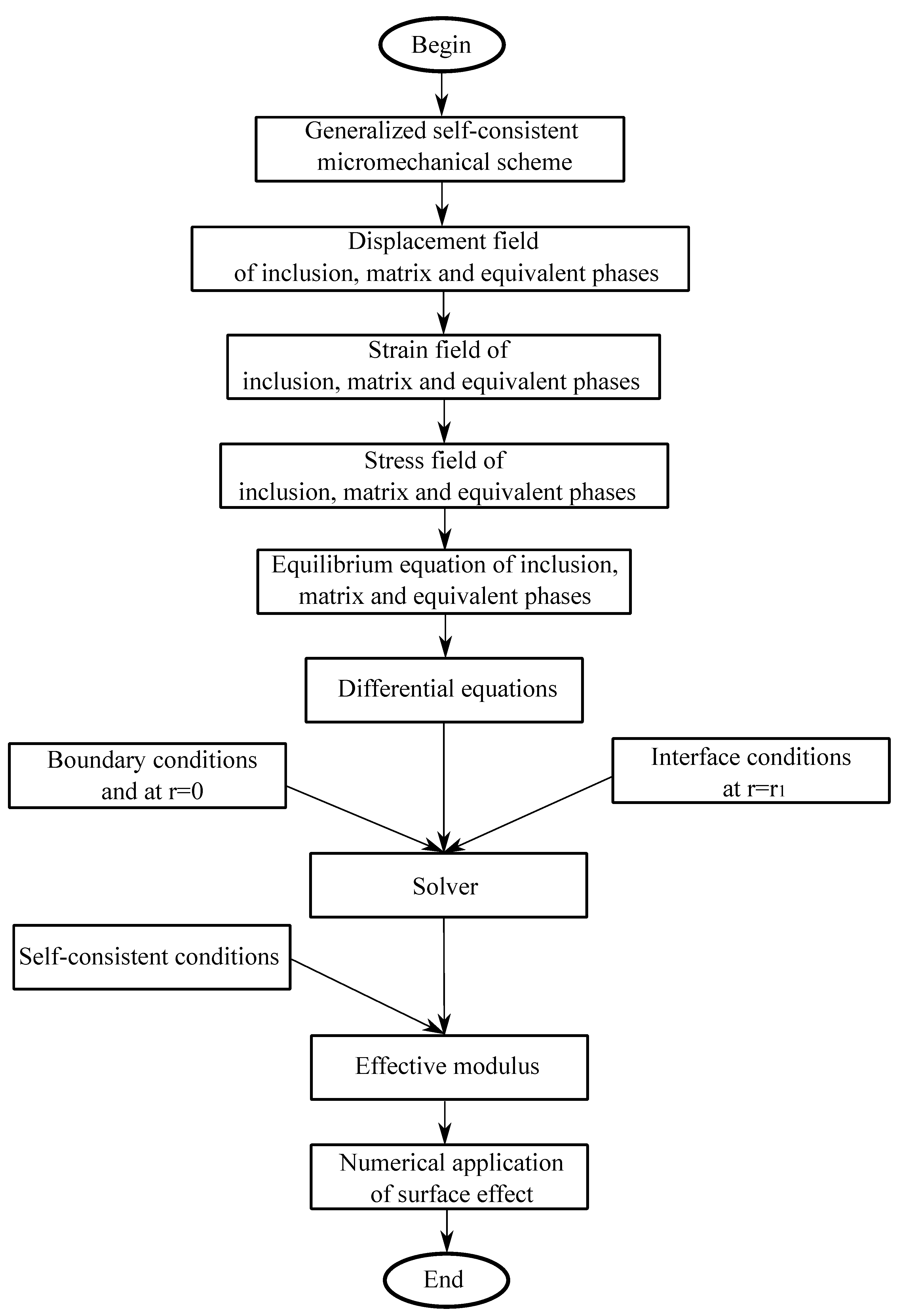
In this section, we present the steps to solve the homogenization problem seeking the effective shear modulus of the material. Figure 5 shows the flowchart of the proposed approach to determine the effective modulus of the heterogeneous material.
Details of the calculation are presented in the following. The form of the solution for the displacement field of each phase is conjectured from the form of the boundary condition (see [31]). By applying the homogeneous strain condition to the boundary presented by Equation (38), we propose the form of the displacement solution
u r ( p ) = f ( p ) ( r ) ( 3 cos 2 θ 1 ) u θ ( p ) = 3 g ( p ) ( r ) sin θ cos θ u φ ( p ) = 0
where the index ( p ) means that we are dealing the inclusion phase ( p = 1 or i), matrix ( p = 2 or m), or equivalent medium ( p = 3 or e), respectively, and f ( p ) and g ( p ) are unknown functions to be solved. Then, we derive the displacement field to obtain the strain field
ε r r ( p ) = d f ( p ) d r ( 3 cos 2 θ 1 ) ε θ θ ( p ) = 1 r ( f ( p ) 2 g ( p ) ) ( 3 cos 2 θ 1 ) + g ( p ) r ε φ φ ( p ) = 1 r ( f ( p ) g ( p ) ) ( 3 cos 2 θ 1 ) g ( p ) r ε r θ ( p ) = 3 ( g ( p ) 2 r f ( p ) r d g ( p ) 2 d r ) sin θ cos θ
Then, by Hooke’s law, we obtain the stress field of each phase
σ r r ( p ) = λ p t r ( ε ( p ) ) + 2 μ p d f ( p ) d r ( 3 cos 2 θ 1 ) σ θ θ ( p ) = λ p t r ( ε ( p ) ) + 2 μ p 1 r ( f ( p ) 2 g ( p ) ) ( 3 cos 2 θ 1 ) + 2 μ p g ( p ) r σ φ φ ( p ) = λ p t r ( ε ( p ) ) + 2 μ p 1 r ( f ( p ) g ( p ) ) ( 3 cos 2 θ 1 ) 2 μ p g ( p ) r σ r θ ( p ) = 6 μ p ( g ( p ) 2 r f ( p ) r d g ( p ) 2 d r ) sin θ cos θ
with t r ( ε ) = ε r r + ε θ θ + ε ϕ ϕ = d f ( p ) d r + 1 r ( 2 f ( p ) 3 g ( p ) ) ( 3 cos 2 θ 1 ) .
We then obtain the equilibrium equations for each phase, in spherical coordinates
σ r r ( p ) r + 1 r σ r θ ( p ) θ + 1 r ( 2 σ r r ( p ) σ θ θ ( p ) σ φ φ ( p ) + σ r θ ( p ) cot θ ) = 0 σ r θ ( p ) r + 1 r σ θ θ ( p ) θ + 1 r ( σ θ θ ( p ) σ φ φ ( p ) ) cot θ + 3 σ r θ ( p ) = 0
These equilibrium equations give a system of second-order differential equations. We solve this system by indicating the precise form of the two functions f and g for each phase, and search for the constants appearing by the boundary conditions and the interface conditions. The system of differential equations obtained is of the form
r 2 d 2 f ( p ) d r 2 + 2 r d f ( p ) d r + a 1 ( p ) r d g ( p ) d r + b 1 ( p ) f ( p ) + c 1 ( p ) g ( p ) = 0 r 2 d 2 g ( p ) d r 2 + 2 r d g ( p ) d r + a 2 ( p ) r d f ( p ) d r + b 2 ( p ) g ( p ) + c 2 ( p ) f ( p ) = 0
where a 1 ( p ) , b 1 ( p ) , c 1 ( p ) , a 2 ( p ) , b 2 ( p ) , c 2 ( p ) are the constants as a function of the moduli λ p and μ p of each phase
a 1 ( p ) = 3 ( λ p + μ p ) λ p + 2 μ p
b 1 ( p ) = 2 ( λ p + 5 μ p ) λ p + 2 μ p
c 1 ( p ) = 3 ( λ p + 3 μ p ) λ p + 2 μ p
a 2 ( p ) = 2 ( λ p + μ p ) μ p
b 2 ( p ) = 6 ( λ p + 2 μ p ) μ p
c 2 ( p ) = 4 ( λ p + 2 μ p ) μ p
To solve this system, we consider its characteristic equation of the form:
x 4 + 2 x 3 + m ( p ) x 2 + ( m ( p ) 1 ) x + c ( p ) = 0 ,
with
m ( p ) = 1 + b 1 ( p ) + b 2 ( p ) a 1 ( p ) a 2 ( p ) = 13 n ( p ) = b 1 ( p ) b 2 ( p ) c 1 ( p ) c 2 ( p ) = 24
We then find that m ( p ) and n ( p ) are constant in the isotropic case. They are independent of the elastic moduli. Then the solutions of Equation (51) are 4 , 2 , 1 and 3. We therefore deduce the form of the two functions f and g for each phase:
f ( p ) = A 1 ( p ) r 4 + A 2 ( p ) r 2 + A 3 ( p ) r + A 4 ( p ) r 3 g ( p ) = B 1 ( p ) r 4 + B 2 ( p ) r 2 + B 3 ( p ) r + B 4 ( p ) r 3
where A j ( p ) and B j ( p ) ( j = 1 , 2 , 3 , 4 ) are constants to be determined. The relationships between the constants are
B 1 ( p ) = 2 3 A 1 ( p ) B 2 ( p ) = 2 μ p 3 ( k p + μ p ) A 2 ( p ) B 3 ( p ) = A 3 ( p ) B 4 ( p ) = 15 k p + 11 μ p 9 k p 6 μ p A 4 ( p )
Below, we seek to simplify the solutions. For the equivalent medium, when the radius r tends towards infinity, it is necessary to satisfy the homogeneous strain condition imposed on the boundary; then, we obtain A 4 ( 3 ) = 0 , B 4 ( 3 ) = 0 and A 3 ( 3 ) = γ 0 , B 3 ( 3 ) = γ 0 . The form of the solutions for the equivalent medium is therefore:
f ( 3 ) = A 1 ( 3 ) r 4 + A 2 ( 3 ) r 2 + γ 0 r g ( 3 ) = B 1 ( 3 ) r 4 + B 2 ( 3 ) r 2 + γ 0 r
Similarly, when the radius r tends toward zero, we consider that f and g are finite. Hence, we obtain the form of solutions for inclusion
f ( 1 ) = A 3 ( 1 ) r + A 4 ( 1 ) r 3 g ( 1 ) = B 3 ( 1 ) r + B 4 ( 1 ) r 3
We still have to solve a system of eight equations with eight unknown constants. The conditions at the interface are, at r = r 1 :
u r ( 2 ) u r ( 1 ) = 0
u θ ( 2 ) u θ ( 1 ) = 0
ε θ θ ( 2 ) ε θ θ s = 0
ε φ φ ( 2 ) ε φ φ s = 0
σ r r ( 2 ) σ r r ( 1 ) = σ θ θ s + σ φ φ s r 1
σ r θ ( 2 ) σ r θ ( 1 ) = 1 r 1 σ θ θ s θ σ θ θ s σ φ φ s r 1 cot θ
where the first two equations are the conditions of continuity of the displacement field, described by Equation (19). The following strain conditions are deduced from Equation (20), the surface part of the strain tensor is continuous across the interface. Finally, the relations of stress discontinuities are represented in Equation (21), with the constitutive law of the interface being given in Equation (28). At the interface at r = r 2 , as this interface between the matrix and the equivalent medium is perfect, we have
u r ( 2 ) = u r ( 3 ) , u θ ( 2 ) = u θ ( 3 ) , σ r r ( 2 ) = σ r r ( 3 ) , σ r θ ( 2 ) = σ r θ ( 3 ) .
We obtain a system of linear equations, which allows us to find the constants sought. This system is of the form
A b = c ,
where the vector of the unknowns b
b = [ B 3 ( 1 ) B 4 ( 1 ) B 1 ( 2 ) B 2 ( 2 ) B 3 ( 2 ) B 4 ( 2 ) B 1 ( 3 ) B 2 ( 3 ) ] T ,
then the vector c
c = [ 0 0 0 0 r 2 10 r 2 10 μ e 5 μ e 5 ] T ,
and the matrix A is given by
A = A 11 . . . . . . A 18 . . . . . . . . . . . . . . . . . . A 81 . . . . . . A 88 .
with the components of matrix A are functions of the elastic moduli of each phase, and of the geometry of the field. Finally, according to the terminology of the self-consistent condition presented in Section 3.3, we obtain an equation that gives the effective shear modulus μ eff as a function of κ s , μ s , κ i , μ i , κ m , μ m , and r 1 , r 2 .
μ eff = F μ ( κ s , μ s , κ i , μ i , κ m , μ m , r 1 , r 2 ) .
Equation (68) is solved by using the consistency condition for the equivalent medium presented previously in Section 3.3. The effective shear modulus of the heterogeneous material is calculated as the positive root of a quadratic equation derived from the above-mentioned consistency condition.

5. Numerical Application

5.1. Input Parameters for Numerical Application

Considering the nanoinclusion of elastic properties E i = 40   GPa and ν i = 0.22 , and the matrix with E m = 4   GPa and ν m = 0.37 (typical values for polymeric materials reinforced with silica nanoparticles [12,35]), we calculate the elastic moduli ( κ i , μ i ), and ( κ m , μ m ) by the relation
κ i = E i 3 ( 1 2 ν i ) , μ i = E i 2 ( 1 + ν i ) , κ m = E m 3 ( 1 2 ν m ) , μ m = E m 2 ( 1 + ν m ) .
We obtain κ i = 23.8095   GPa , μ i = 16.3934   GPa and κ m = 5.1282   GPa , μ m = 1.4599   GPa . In the following, we offer the choice of surface elastic properties κ s and μ s for numerical application. The elastic surface moduli have already been calculated by several researchers, by the method of stress simulation at the interface (see [36]), or by atomistic simulation (see [37]), or by simulating a fine or stiff interphase using the asymptotic approach (see [17,26,29,38]). In this case, we use the approximation proposed in [17,26,29,38] for a coherent imperfect interface. We propose a Young’s modulus ratio E s E m = 1000 , the surface Poisson’s ratio ν s = 0.25 , and the constant thickness interface h = 0.001   nm = 10 12   m . Such a very thin and very stiff layer between the matrix and the nanoinclusion is considered in order to apply the linearly elastic interface stress model earlier proposed by Benveniste [29]. We present the formula that gives the values of elastic surface moduli as a function of E s , ν s and h:
κ s = h E s ( 1 ν s 2 ) , μ s = h E s 2 ( 1 ν s ) .
We obtain κ s = 4.2667   N / m and μ s = 2.6667   N / m . In the following section, we offer a numerical simulation of the surface effect on the effective shear modulus using the micromechanical system.

5.2. Surface Effect on Effective Shear Modulus

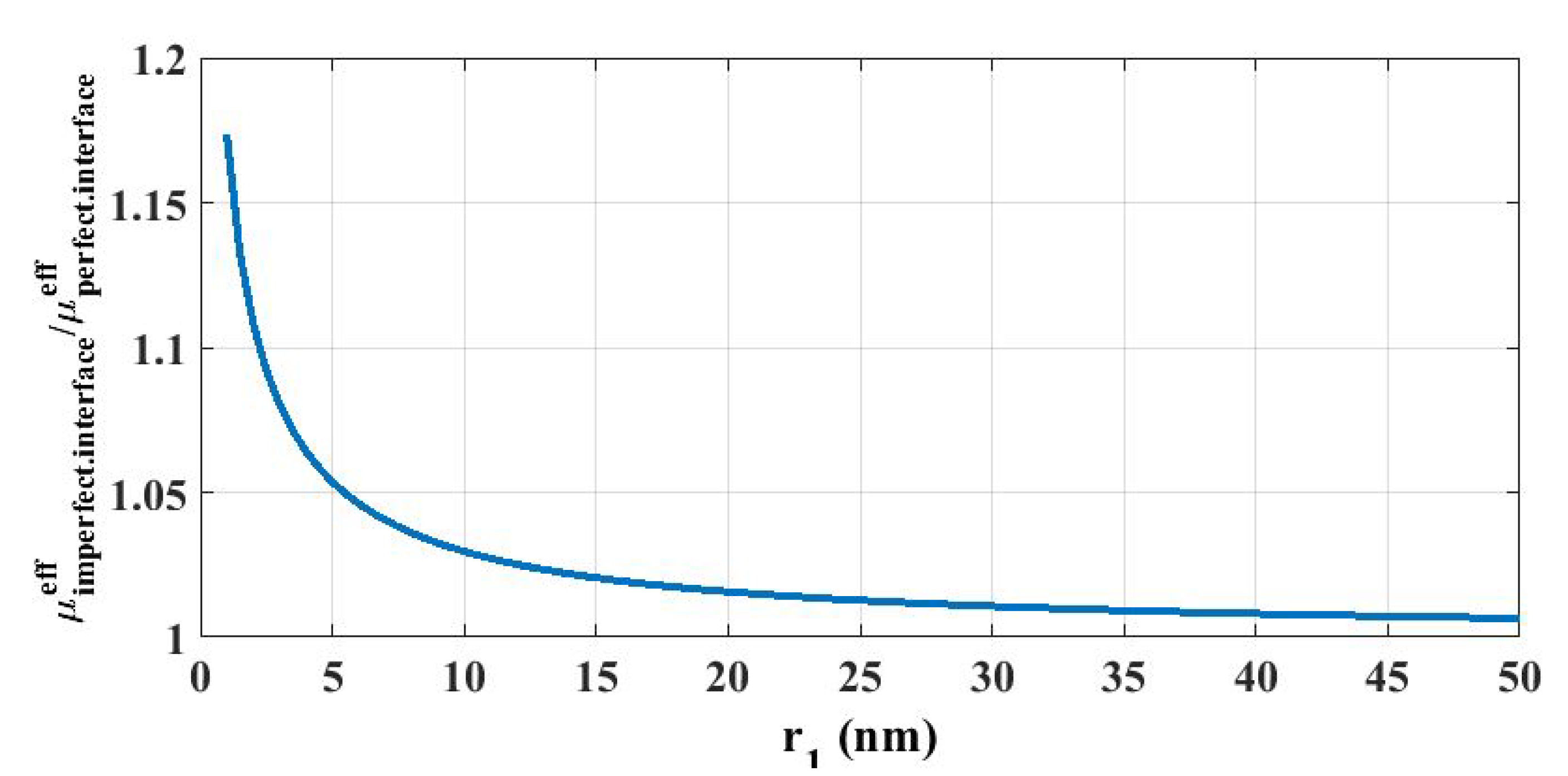
Using the input parameters introduced above, we propose here to illustrate the surface effects on the effective shear modulus (see Equation (68)). We use the notation μ imperfect . interface eff and μ perfect . interface eff for the effective shear modulus using imperfect and perfect interfaces, respectively. Figure 6 shows the surface effects of the heterogeneous material containing nanoinclusions. We can see that there is an increase in effective properties, and the smaller the radius of the fillers, the greater the difference in the property. If the radius of inclusion r 1 5 nm, this increase is very marked. If the radius of inclusion r 1 > 50 nm, the difference in effective properties is very small, and we can therefore consider that there is no longer any surface effect. In other words, a classical solution can be applied in this case. On the other hand, by using the present approach, if the radius of inclusion tends to an infinitesimal value, the specific area of the reinforcement phase is then increased to an infinite value. Such an augmentation leads to an increase in surface interactions between the matrix and the reinforcement, and therefore an increase in the effective properties. However, this point should be revisited from both experimental and physical points of view at the smallest scales. For instance, in Wang and Ye [39], the radial displacement field due to surface effect has been derived and showed that the effect of an imperfect interface is only profound within the region near the interface.
From an experimental point of view, such surface effect on the effective elastic properties has been clearly demonstrated, especially in the case of polymer-based particulate nanocomposites. A typical example can be found in [40], where a polysiloxane matrix was reinforced by silica nanoparticles of three different sizes −15, 35 and 60 nm, respectively. The surface effect on the Young’s modulus of nanocomposite was clearly observed by comparing the results for the nanofillers with diameters of 15 and 35 nm, respectively. For instance, the effective Young’s modulus was about 4.3 and 3.95 GPa, using nanofillers of 15 and 35 nm, respectively (at the same volume fraction of reinforcement of 10%), where the Young’s modulus of the pure polymer was 3 GPa. However, such surface effect was not observed with 60 nm particles. A possible explanation is that for this size of reinforcement (i.e., larger than 50 nm in diameter), the specific area of the nanoparticles is decreased, leading to a decrease in surface interactions and therefore a decrease of the macroscopic properties. Finally, other experimental results on surface effect are available such as [41,42,43,44].

6. Conclusions

In this work, we are interested in the multiscale analysis of heterogeneous materials presenting surface effects. A model of the coherent imperfect elastic interface was used, together with a generalized self-consistent micromechanical scheme for determining the effective elastic properties of the nano-reinforced materials. In this study, the calculation for effective shear modulus was detailed. Numerical application showed that the imperfect interface model was capable of taking the surface effect as a function of nanofiller size into account.
In further studies, the surface energy should be discussed, to describe whether or not the surface elasticity tensor is positive-definite. In addition, both experiments and numerical simulations (for instance, in Molecular Dynamics) demonstrated the existence of a perturbed area at the boundary between the inclusion and the matrix phase. From a probabilistic standpoint, the elastic properties of that perturbed area randomly fluctuate from point to point. Consequently, a probabilistic investigation should be considered in future research for describing the surface effect in nano-reinforced materials.

Funding

This research did not receive any specific grant from funding agencies in the public, commercial, or not-for-profit sectors.

Conflicts of Interest

The authors declare that there is no conflict of interest.

Appendix A. Projection Operators

Consider the two projection operators defined by
𝕟 ( x ) = n ( x ) n ( x ) ,
𝕥 ( x ) = 𝕚 𝕟 ( x ) ,
where 𝕚 denotes the second-order symmetric identity tensor. These operators 𝕟 ( x ) and 𝕥 ( x ) represent the projections in the normal direction n ( x ) and in the tangential direction to Γ at point x , respectively. Note that 𝕟 ( x ) and 𝕥 ( x ) are two orthogonal and complementary projectors, such that
𝕟 2 = 𝕟 , 𝕥 2 = 𝕥 , 𝕟 T = 𝕟 , 𝕥 T = 𝕥 , 𝕟 𝕥 = 𝕥 𝕟 = 0 , 𝕟 + 𝕥 = 𝕚 ,
where T represents the transpose operator.
From these two projection operators (of the second order), we can define the following fourth-order projection operators
P ( x ) = 𝕥 ( x ) ̲ ¯ 𝕥 ( x ) ,
P ( x ) = I P ( x ) ,
with index notation:
P i j k l = 1 2 ( 𝕥 i k 𝕥 j l + 𝕥 i l 𝕥 j k ) ,
where these two projection operators satisfy the following properties
P 2 = P , P 2 = P , P T = P , P T = P , P : P = P : P = 0 , P + P = I ,
with I being the fourth-order identity tensor. These properties show that P and P are orthogonal and complementary.

Appendix B. Elastic Moduli κ and μ

Elastic properties of materials are commonly described by Young’s modulus, Poisson’s ratio, bulk modulus, and shear modulus [32,45]. In the case of isotropic materials, only two of the above-mentioned elastic coefficients are independent [46]. In other words, other elastic coefficients are computed by using the relations provided by the elasticity’s theory. In engineering practice, the bulk modulus κ and the shear modulus μ are commonly chosen as the two independent moduli [47,48]. The bulk modulus characterizes the strain response of a material to hydrostatic stress involving a change in volume without change of shape. In other words, the bulk modulus of a material is a measure of how resistant to hydrostatic compression that material is. On the other hand, the shear modulus relates to the strain response of a material to shear stress. However, in this case, it involves a change of shape without a change of volume.

References

  1. Matthews, F.L.; Rawlings, R.D. Composite Materials: Engineering and Science; Woodhead Publishing: Cambridge, UK, 1999. [Google Scholar]
  2. Le, T.-T. Prediction of tensile strength of polymer carbon nanotube composites using practical machine learning method. J. Compos. Mater. 2020. [Google Scholar] [CrossRef]
  3. Staber, B.; Guilleminot, J.; Soize, C.; Michopoulos, J.; Iliopoulos, A. Stochastic modeling and identification of a hyperelastic constitutive model for laminated composites. Comput. Methods Appl. Mech. Eng. 2019, 347, 425–444. [Google Scholar] [CrossRef] [Green Version]
  4. Le, T.-T. Modélisation Stochastique, en Mécanique des Milieux Continus, de L’interphase Inclusion-Matrice à Partir de Simulations en Dynamique Moléculaire. Ph.D. Thesis, University of Paris-Est Marne-la-Vallée, Paris, France, October 2015. [Google Scholar]
  5. Ajayan, P.M.; Schadler, L.S.; Braun, P.V.; Keblinski, P. Nanocomposite Science and Technology; Wiley-VCH Verlag GmbH: Weinheim, Germany; Chichester, UK, 2015. [Google Scholar]
  6. Duong, H.T.; Phan, H.C.; Le, T.-T.; Bui, N.D. Optimization design of rectangular concrete-filled steel tube short columns with Balancing Composite Motion Optimization and data-driven model. Structures 2020, 28, 757–765. [Google Scholar] [CrossRef]
  7. Le, T.-T. Practical Machine Learning-based Prediction Model for Axial Capacity of Square CFST Columns. Mech. Adv. Mater. Struct. 2020, 2020, 8832522. [Google Scholar]
  8. Hussain, F.; Hojjati, M.; Okamoto, M.; Gorga, R.E. Review article: Polymer-matrix Nanocomposites, Processing, Manufacturing, and Application: An Overview. J. Compos. Mater. 2006, 40, 1511–1575. [Google Scholar] [CrossRef]
  9. Hanemann, T.; Szabó, D.V. Polymer-Nanoparticle Composites: From Synthesis to Modern Applications. Materials 2010, 3, 3468–3517. [Google Scholar] [CrossRef]
  10. Papon, A.; Saalwächter, K.; Schäler, K.; Guy, L.; Lequeux, F.; Montes, H. Low-Field NMR Investigations of Nanocomposites: Polymer Dynamics and Network Effects. Macromolecules 2011, 44, 913–922. [Google Scholar] [CrossRef]
  11. Berriot, J.; Lequeux, F.; Monnerie, L.; Montes, H.; Long, D.; Sotta, P. Filler–elastomer interaction in model filled rubbers, a 1H NMR study. J. Non-Cryst. Solids 2002, 307–310, 719–724. [Google Scholar] [CrossRef]
  12. Brown, D.; Marcadon, V.; Mélé, P.; Albérola, N.D. Effect of Filler Particle Size on the Properties of Model Nanocomposites. Macromolecules 2008, 41, 1499–1511. [Google Scholar] [CrossRef]
  13. Ghanbari, A.; Ndoro, T.V.M.; Leroy, F.; Rahimi, M.; Böhm, M.C.; Müller-Plathe, F. Interphase Structure in Silica–Polystyrene Nanocomposites: A Coarse-Grained Molecular Dynamics Study. Macromolecules 2012, 45, 572–584. [Google Scholar] [CrossRef]
  14. Guilleminot, J.; Soize, C. Stochastic modeling of anisotropy in multiscale analysis of heterogeneous materials: A comprehensive overview on random matrix approaches. Mech. Mater. 2012, 44, 35–46. [Google Scholar] [CrossRef] [Green Version]
  15. Le, T.-T. Probabilistic modeling of surface effects in nano-reinforced materials. Comput. Mater. Sci. 2021, 186, 109987. [Google Scholar] [CrossRef]
  16. Le, T.-T. Probabilistic investigation of the effect of stochastic imperfect interfaces in nanocomposites. Mech. Mater. 2020, 151, 103608. [Google Scholar] [CrossRef]
  17. Duan, H.L.; Wang, J.; Huang, Z.P.; Luo, Z.Y. Stress concentration tensors of inhomogeneities with interface effects. Mech. Mater. 2005, 37, 723–736. [Google Scholar] [CrossRef]
  18. Duan, H.L.; Wang, J.; Huang, Z.P.; Karihaloo, B.L. Size-dependent effective elastic constants of solids containing nano-inhomogeneities with interface stress. J. Mech. Phys. Solids 2005, 53, 1574–1596. [Google Scholar] [CrossRef]
  19. Choi, J.; Shin, H.; Yang, S.; Cho, M. The influence of nanoparticle size on the mechanical properties of polymer nanocomposites and the associated interphase region: A multiscale approach. Compos. Struct. 2015, 119, 365–376. [Google Scholar] [CrossRef]
  20. Kim, B.; Choi, J.; Yang, S.; Yu, S.; Cho, M. Multiscale modeling of interphase in crosslinked epoxy nanocomposites. Compos. Part B Eng. 2017, 120, 128–142. [Google Scholar] [CrossRef]
  21. Le, T.T.; Guilleminot, J.; Soize, C. Stochastic continuum modeling of random interphases from atomistic simulations. Application to a polymer nanocomposite. Comput. Methods Appl. Mech. Eng. 2016, 303, 430–449. [Google Scholar] [CrossRef] [Green Version]
  22. Staber, B.; Guilleminot, J. Stochastic modeling and generation of random fields of elasticity tensors: A unified information-theoretic approach. Comptes Rendus Mécanique 2017, 345, 399–416. [Google Scholar] [CrossRef]
  23. Guilleminot, J.; Le, T.T.; Soize, C. Stochastic framework for modeling the linear apparent behavior of complex materials: Application to random porous materials with interphases. Acta Mech. Sin. 2013, 29, 773–782. [Google Scholar] [CrossRef] [Green Version]
  24. Baek, K.; Shin, H.; Yoo, T.; Cho, M. Two-step multiscale homogenization for mechanical behaviour of polymeric nanocomposites with nanoparticulate agglomerations. Compos. Sci. Technol. 2019, 179, 97–105. [Google Scholar] [CrossRef]
  25. Gurtin, M.E.; Murdoch, A.I. A continuum theory of elastic material surfaces. Arch. Ration. Mech. Anal. 1975, 57, 291–323. [Google Scholar] [CrossRef]
  26. Quang, H.L.; He, Q.C. Variational principles and bounds for elastic inhomogeneous materials with coherent imperfect interfaces. Mech. Mater. 2008, 40, 865–884. [Google Scholar] [CrossRef]
  27. Hashin, Z. Thin interphase/imperfect interface in elasticity with application to coated fiber composites. J. Mech. Phys. Solids 2002, 50, 2509–2537. [Google Scholar] [CrossRef]
  28. Hashin, Z. Thermoelastic properties of particulate composites with imperfect interface. J. Mech. Phys. Solids 1991, 39, 745–762. [Google Scholar] [CrossRef]
  29. Benveniste, Y. A general interface model for a three-dimensional curved thin anisotropic interphase between two anisotropic media. J. Mech. Phys. Solids 2006, 54, 708–734. [Google Scholar] [CrossRef]
  30. Gu, S.-T. Contributions à la Modélisation des Interfaces Imparfaites et à L’homogénéisation des Matériaux Hétérogènes. Ph.D. Thesis, Université Paris-Est, Champs-sur-Marne, France, February 2008. [Google Scholar]
  31. Quang, H.L.; He, Q.C. Size-dependent effective thermoelastic properties of nanocomposites with spherically anisotropic phases. J. Mech. Phys. Solids 2007, 55, 1899–1931. [Google Scholar] [CrossRef]
  32. Yvonnet, J.; Quang, H.L.; He, Q.C. An XFEM/level set approach to modelling surface/interface effects and to computing the size-dependent effective properties of nanocomposites. Comput. Mech. 2008, 42, 119–131. [Google Scholar] [CrossRef] [Green Version]
  33. Povstenko, Y.Z. Theoretical investigation of phenomena caused by heterogeneous surface tension in solids. J. Mech. Phys. Solids 1993, 41, 1499–1514. [Google Scholar] [CrossRef]
  34. Christensen, R.M.; Lo, K.H. Solutions for effective shear properties in three phase sphere and cylinder models. J. Mech. Phys. Solids 1979, 27, 315–330. [Google Scholar] [CrossRef]
  35. Marcadon, V.; Brown, D.; Hervé, E.; Mélé, P.; Albérola, N.D.; Zaoui, A. Confrontation between Molecular Dynamics and micromechanical approaches to investigate particle size effects on the mechanical behaviour of polymer nanocomposites. Comput. Mater. Sci. 2013, 79, 495–505. [Google Scholar] [CrossRef]
  36. Müller, P.; Saúl, A. Elastic effects on surface physics. Surf. Sci. Rep. 2004, 54, 157–258. [Google Scholar] [CrossRef]
  37. Shenoy, V.B. Atomistic calculations of elastic properties of metallic fcc crystal surfaces. Phys. Rev. B 2005, 71, 094104. [Google Scholar] [CrossRef] [Green Version]
  38. Wang, J.; Duan, H.L.; Zhang, Z.; Huang, Z.P. An anti-interpenetration model and connections between interphase and interface models in particle-reinforced composites. Int. J. Mech. Sci. 2005, 47, 701–718. [Google Scholar] [CrossRef]
  39. Wang, M.; Ye, W. Size-dependent elastic field of nano-inhomogeneity: From interface effect to interphase effect. Arch. Appl. Mech. 2020, 90, 2319–2333. [Google Scholar] [CrossRef]
  40. Douce, J.; Boilot, J.-P.; Biteau, J.; Scodellaro, L.; Jimenez, A. Effect of filler size and surface condition of nano-sized silica particles in polysiloxane coatings. Thin Solid Films 2004, 466, 114–122. [Google Scholar] [CrossRef]
  41. Liu, Y.Q.; Cong, H.T.; Wang, W.; Sun, C.H.; Cheng, H.M. AlN nanoparticle-reinforced nanocrystalline Al matrix composites: Fabrication and mechanical properties. Mater. Sci. Eng. A 2009, 505, 151–156. [Google Scholar] [CrossRef]
  42. Chabert, E. Propriétés Mécaniques de Nanocomposites à Matrice Polymère: Approche Expérimentale et Modélisation. Ph.D. Thesis, Lyon, INSA, Villeurbanne, France, January 2002. [Google Scholar]
  43. Vassiliou, A.; Bikiaris, D.; Chrissafis, K.; Paraskevopoulos, K.M.; Stavrev, S.Y.; Docoslis, A. Nanocomposites of isotactic polypropylene with carbon nanoparticles exhibiting enhanced stiffness, thermal stability and gas barrier properties. Compos. Sci. Technol. 2008, 68, 933–943. [Google Scholar] [CrossRef] [Green Version]
  44. Chung, I.; Cho, M. Recent Studies on the Multiscale Analysis of Polymer Nanocomposites. Multiscale Sci. Eng. 2019, 1, 167–195. [Google Scholar] [CrossRef] [Green Version]
  45. Guilleminot, J.; Soize, C. On the Statistical Dependence for the Components of Random Elasticity Tensors Exhibiting Material Symmetry Properties. J. Elast. 2013, 111, 109–130. [Google Scholar] [CrossRef] [Green Version]
  46. Doan, T.; Le-Quang, H.; To, Q.-D. Effective elastic stiffness of 2D materials containing nanovoids of arbitrary shape. Int. J. Eng. Sci. 2020, 150, 103234. [Google Scholar] [CrossRef]
  47. Le, T.-T. Analysis of elastic deformation of amorphous polyethylene in uniaxial tensile test by using molecular dynamics simulation. Comput. Methods Mater. Sci. 2020, 20, 38–44. [Google Scholar]
  48. Soize, C.; Desceliers, C.; Guilleminot, J.; Le, T.-T.; Nguyen, M.-T.; Perrin, G.; Allain, J.-M.; Gharbi, H.; Duhamel, D.; Funfschilling, C. Stochastic representations and statistical inverse identification for uncertainty quantification in computational mechanics. In Proceedings of the UNCECOMP 2015, 1st ECCOMAS Thematic International Conference on Uncertainty Quantification in Computational Sciences and Engineering, Crete Island, Greece, 25–27 May 2015; pp. 1–26. [Google Scholar]
Figure 1. Subdomains Ω ( 1 ) and Ω ( 2 ) separated by interface Γ .
Jcs 04 00172 g001
Figure 2. Three-phase (a) and two-phase (b) configurations.
Jcs 04 00172 g002
Figure 3. Microstructure.
Jcs 04 00172 g003
Figure 4. Generalized self-consistent micromechanical system.
Jcs 04 00172 g004
Figure 5. Flowchart of the proposed approach to determine the effective modulus of the heterogeneous material.
Jcs 04 00172 g005
Figure 6. Surface effect on the μ imperfect . interface eff μ perfect . interface eff ratio.
Jcs 04 00172 g006
Publisher’s Note: MDPI stays neutral with regard to jurisdictional claims in published maps and institutional affiliations.