Thermal Transformation of End-of-Life Latex to Valuable Materials
by
 , and
, and
Enamul Haque
1,2,3, 
Farshid Pahlevani
4,* ,
,
Narjes Gorjizadeh
4,
Rumana Hossain
4 and
Veena Sahajwalla
4 1
School of Materials Science and Engineering, Zhejiang Sci-Tech University, Hangzhou 310018, Zhejiang, China
2
School of Engineering, RMIT University, Melbourne, VIC 3001, Australia
3
Laboratory of Sustainable Technology, School of Chemical & Biomolecular Engineering, The University of Sydney, Sydney, NSW 2008, Australia
4
Centre for Sustainable Materials Research and Technology, SMaRT@UNSW, School of Materials Science and Engineering, UNSW, Sydney, NSW 2052, Australia
*
Author to whom correspondence should be addressed.
J. Compos. Sci. 2020, 4(4), 166; https://doi.org/10.3390/jcs4040166
Submission received: 30 September 2020
/
Revised: 21 October 2020
/
Accepted: 26 October 2020
/
Published: 4 November 2020
(This article belongs to the Special Issue Feature Papers in Journal of Composites Science in 2020)
Abstract
:Recent studies have demonstrated that carbon nanomaterials have huge potential in composite applications, but there is a continuous quest for identifying the most viable technique for producing this material. In this study, the possibility of using an innovative approach for the synthesis of value-added carbon nanomaterials and green gases from end-of-life soft mattress materials (latex) was investigated. Thermogravimetric analysis (TGA) was used to determine the thermal degradation of latex. Quantitative gas analysis at three different temperatures by infrared spectroscopy (IR) suggested that small gas molecules, especially CH4, could be produced at a higher temperature. The carbon residues produced after gas analysis were characterised by XRD, SEM, TEM, XPS, and Raman spectroscopy, suggesting the possibility of direct synthesis of carbon nanomaterials from waste latex. These carbon materials have Na, Zn, Si, and K in their structure, and further study is needed for understanding the effect of these elements on composite properties. Our study demonstrated that heat treatment of waste latex at 1000 °C for 15 min produced carbon materials, which contained 7–16% S and 1.2–2% N, and gases, such as CH4, could be synthesised.
1. Introduction
Several studies have shown that carbon nanomaterials with heteroatoms (nitrogen, boron, sulphur and phosphorous) as fillers are a promising way to further improve the properties of composite materials [1]. Carbon nanomaterials play an important role in different applications of composite materials. Carbon nanomaterials containing nitrogen have been proved to promote the interaction of sulphur atoms with the carbon matrix [2]. Sulphur can also enhance the affinity of polysulfides to the carbons with better cycling behaviour, which can be used in applications, such as electrodes [3,4]. Zhou et al. [5] presented a Li/polysulphide battery with a high-energy density and long-cyclic life using three-dimensional nitrogen/sulphur co-doped graphene sponge electrodes.
In addition, the presence of heteroatoms in carbon materials enhances the performance of carbon nanomaterials in electrochemistry applications [6]. Among those, nitrogen (N) is reckoned as a peerless addition. Upon the introduction of more electronegative N atoms into sp2 hybridized C frameworks, the electric property and chemical activity can be modified [7,8,9,10]. Wang et al. demonstrated that the spin density and charge distribution of a C atom could be influenced by the neighbour N dopants, which induces an “activation region” on the carbon surface that may directly participate in catalytic reactions [11]. Complementing N element, sulphur (S) is receiving increasing attention in carbon materials research very recently. As is known, N is preferential in tuning electronic properties of the carbon materials, whereas S is easy to polarize because of large lone pairs, inducing high chemical reactivity of the carbon materials [1,12]. Furthermore, a recent density functional theory (DFT) calculation highlights the importance of changing spin density via S doping in catalysis [13,14]. More importantly, N, S dual doping may induce redistribution of spin and charge densities, providing a large number of active sites favourable for high catalytic activity [1,12,15,16]. Moreover, doped porous carbons have great potential for use in supercapacitors due to their large gravimetric capacitance and electrical conductivity [17,18,19]. Numerous efforts have been devoted to S-doped carbon, a universal heterogeneous carbon-based electrode material [20].
Carbon nanomaterials, such as graphene, porous carbon, carbon sphere, carbon fibre, carbon nanotube (CNT), and graphene/CNT composite, have been synthesised in single/multiple steps via pyrolysis/thermal treatment and hydrothermal and activation process [21,22], using various precursors: (a) 5-Amino-1,3,4-thiadiazole-2-thiol (C2H3N3S2) and graphene oxide [21], (b) NaCl, cysteine [HO2CCH(NH2)CH2SH] [23], (c) benzyl disulphide, graphene oxide [24], (d) NH3 and H2S gas, graphene-silica [25], (e) urea, thiourea, graphene oxide (GO), CNT [26], (f) D-glucose, L-cysteine, KOH, sulphur powder [27], (g) sodium citrate, cysteine [28], (h) PPy precursors, KOH, S [29], (i) resorcinol and furaldehyde, phosphorus pentasulfide [30], (j) toluenethiol and sulphur, N-CNT, (k) urea, thiourea, and CNT [22], etc. All of these processes are time-consuming (1 h–171 h), multi-step processes, and expensive precursors are used as starting materials. Hence, a simple, low-cost, single-step process of using precursors without any expense is needed to synthesise co-doped (N/S) carbon-based materials for valuable applications.
The 48 million tonnes of solid waste materials generated each year in Australia’s material-intensive economy are handled through Australia’s 2846 waste management facilities [31]. These solid waste materials include household waste, e-waste, plastics, tyres, construction materials, etc., and among them, the waste mattress components are a big problem to handle due to large volume. Each year, Australians send an estimated 1.25 million mattresses to landfills around Australia [32]. Mattresses are extremely lightweight and consume significant landfill airspace [32,33,34]. In detail, mattresses are also bulky items, using up around 0.75 cubic meters of landfill space [33]. Due to this bulkiness and because the springs cause excessive wear to landfill machinery, the recycling of a mattress component is very important to reduce the environmental problem created not only in Australia but also all over the world.
The mattress is composed of mainly three types of materials: steel, wood, and foam/latex. Among these components, latex has the largest volume per weight ratio. Latex is mainly composed of rubber hydrocarbons, nonrubber hydrocarbon substances, mainly proteins and peptones, nitrogen, moisture, and some residue salt of phosphorous and alkaline metals [34,35].
The aim of this study was to investigate the possibility of producing value-added materials from waste latex through selective thermal transformation and monitoring the formation of off-gases during this process. In the literature, a number of waste materials are reported for the characterization of gaseous species via a high-temperature transformation method, mainly including waste tyres [36], waste plastic [36], paint and tar stalk [37], wheat-straw [38], maize, cotton, and rice stalk [39], dyestuff production waste [10], biomass [18], metal-chelate gel [40], sewage sludge [41], medical waste [24], ethylene-vinyl acetate co-polymers [42], palm oil waste [43], hemicellulose, cellulose, and lignin [44], bisphenol A polycarbonate [45], poly(succinimide) and sodium poly(aspartate) [46].
Thermogravimetric analysis (TGA) and TGA-Fourier transform infrared spectroscopy (TGA-FTIR) are well-established methods in the determination of the weight loss characteristics and the associated reaction kinetics, as well as proper investigation of evolved gaseous species during high-temperature transformation [36]. The thermogravimetric analysis involves the thermal degradation of the sample (typically ~5–20 mg sample weight) in an inert atmosphere with simultaneous recording of the loss in weight of the sample as the temperature is raised at a uniform rate. Thermogravimetric analysis of waste materials has been widely investigated by many reporters in the literature [47,48,49,50,51,52]. In addition, FTIR, connected with TGA, precisely demonstrates the breaking of the chemical structure with evolved gases of low molecular weight to high molecular weight, depending on the degradation temperatures of the heat transformation process. For example, Zhu et al. investigated the pyrolysis of medical waste by using coupled TGA-Fourier transform infrared spectrometry (TGA-FTIR) [24]. Similar techniques were followed by Yang et al. [53] and Guintoli et al. [54] to investigate palm oil waste and agricultural waste, respectively. Furthermore, Ischia et al. conducted a thermogravimetric analysis coupled to a mass spectrometer to examine the pyrolysis of sewage sludge [55].
In this work, the possibility of using a selective thermal transformation technique for transforming waste latex to value-added material was studied. The evolved gases were characterised by using coupled TGA-Fourier transform infrared spectrometry. In addition, the final products after high-temperature transformation were also characterised to understand the future possibility of using this material.
2. Materials and Methods
Latex from waste mattress was collected from Resource Recovery Australia. To examine the chemical composition of collected latex, X-ray photoelectron spectroscopy (XPS, ESCALAB250Xi, Thermo scientific, London, UK; X-ray source: mono-chromated Al K alpha, Power: 164W (10.8 mA and 15.2 kV); binding energy reference: C1s = 285.0 eV for adventitious hydrocarbon) was used. Then thermal degradation and gas identification were conducted using TGA-FTIR (Thermogravimetric-analyser model Perkin Elmer Pyris 1) from a low temperature (30 °C) to a high temperature (1200 °C) at a heating rate of 20 °C/min with the initial sample weight of 5.469 mg.
Selective thermal transformation of latex was investigated using a preheated high temperature furnace (Model: HTF 7060, Ceramic Engineering, Mortdale, Australia) and quantitative gas analysis was conducted by an Infrared (IR) gas analyser (Uras 26, ABB Automation GmbH, Frankfurt, Germany). For thermal transformation, 0.3 g of latex was put in a high purity alumina crucible and placed on graphite sample holder. This assembly pushed into the cold zone (150~200 °C) of a high-temperature horizontal tube furnace with the help of a graphite rod. It was kept in the cold zone for 12 min to avoid thermal shock, and then it was pushed into the hot zone (three different temperatures were studied: 600 °C, 800 °C, and 1000 °C) under argon gas flow at a rate of 1 L/min during heat treatment. The gas outlet was connected to an infrared (IR) analyser for the continuous monitoring of CO, CO2, and CH4 gases produced during heat treatment. The heat treatment was carried out for 15 min, then samples were pulled back into the cold zone and kept there for 20 min to avoid thermal shock and re-oxidation of the final residual product after gas production.
The residual products were collected in a glass vial, and furthermore the structures of these products were examined by XPS (XPS, ESCALAB250Xi, Thermo scientific, London, UK) and Raman Spectroscopy (InVia, Renishaw using an Ar+ ion 70 laser at λ = 514.5 nm). The microstructure of the latex before and after selective thermal transformation was also investigated by an Oxford system attached with a Carl Zeiss AURIGA® CrossBeam® field emission gun scanning electron microscopy (FEG SEM) workstation and TEM equipped with a field emission gun (Philips CM 200, Amsterdam, The Netherlands).
3. Results and Discussion
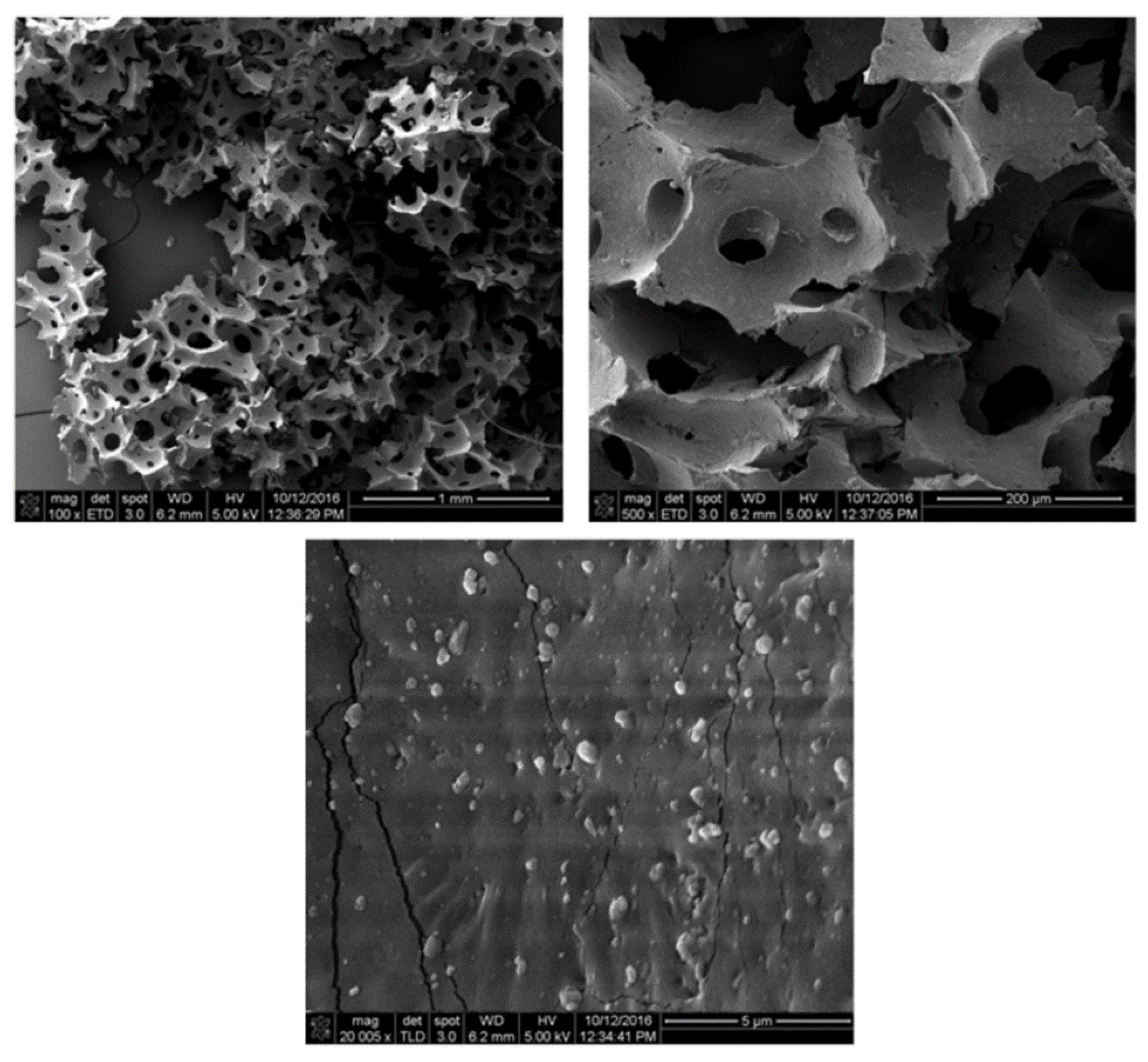
To examine the morphological structure of latex, we used a scanning electron microscope (SEM), as shown in Figure 1. The low resolution microscope image shows the foam like homogeneous porous structure. Some other nano particles were observed from a high resolution SEM image. To understand the chemical structure of latex, XPS analysis was conducted.
To understand the chemical components present in the surface of latex material, XPS analyses were conducted. From the total XPS spectra (Figure 2), it was noted that latex is mainly composed of C (73.22%) and O (12.46%), and also some other elements like Si (11.42%), Zn (2.11%) as well as N (0.79%). The deconvoluted C1s spectra demonstrates the surface functionalities with carbon atom. The high-resolution C1s spectrum of the latex reveal that there are three main components arising at 284.76, 286.35, and 288.75 eV for C = C (aromatic rings), C–O (alkoxy and epoxy), and C = O (carboxyl) groups respectively [56].
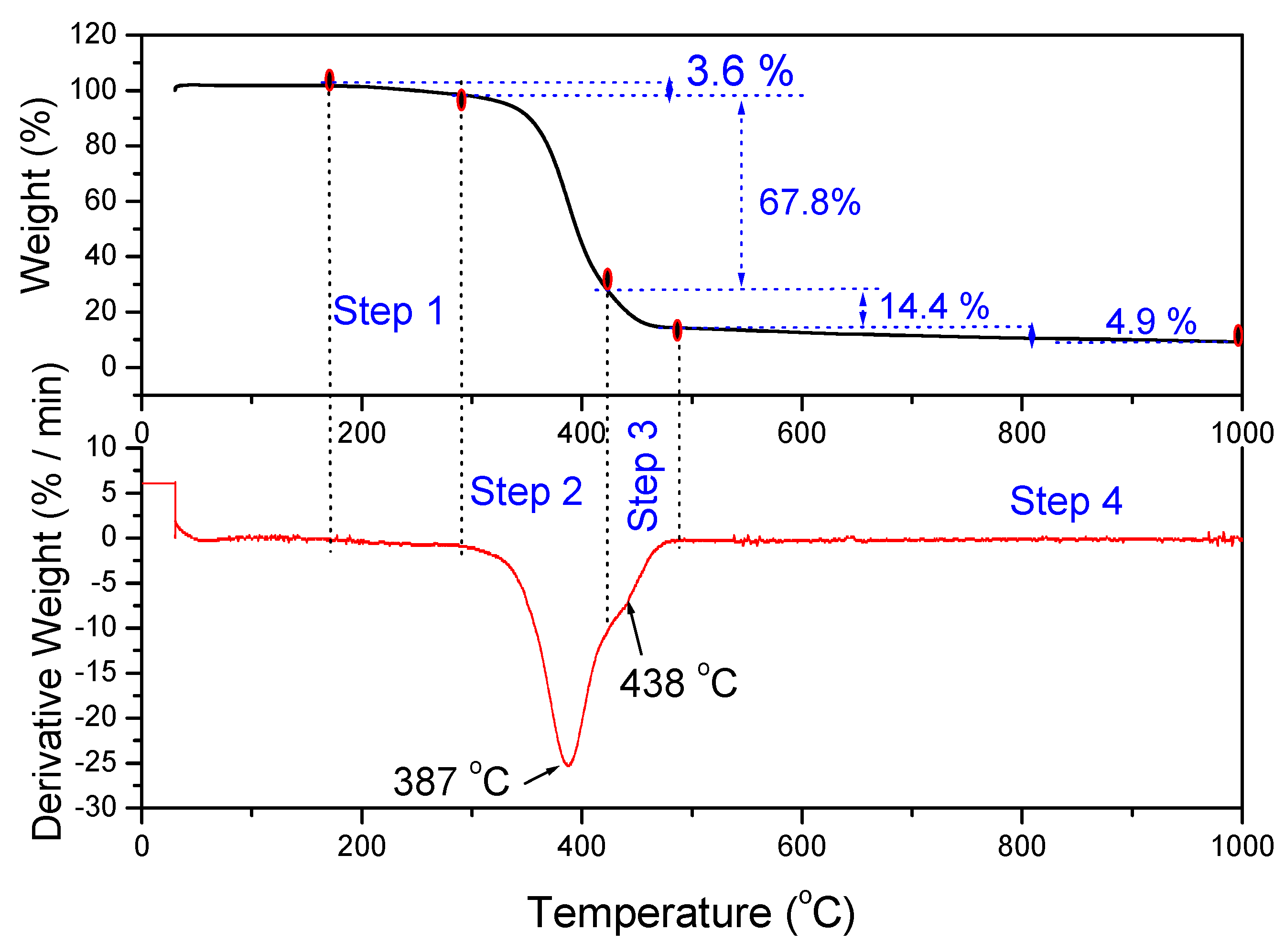
Thermogravimetric analysis (TGA) was also carried out to determine polymer degradation during continuous heating from 30 °C to 1000 °C at a heating rate of 20 °C/min. The TGA and derivative thermogravimetric (DTG) results are shown in Figure 3. The TGA (Figure 3) shows the heat transformation of latex which degrades in four stages of weight loss. The DTG curve shows that significant transformation of latex took place in two temperatures: a main step, which is the origin of the DTG peak at about 387 °C, and a small secondary step seen as a shoulder at somewhat higher temperature (about 438 °C).
The thermal decomposition of waste latex began at the first step from 169 °C to 200 °C, with 3.6% weight loss for volatile compounds. Significant loss of mass occurred in Step 2 and Step 3. The maximum weight loss (67.8%) was found to occur in Step 2 from 289–330 °C which corresponds to the structural decomposition of latex polymer; and Step 3 corresponds to the second height weight loss (14.4%) from 423–488 °C which was also for the second phase decomposition of polymer of latex. The mass loss slowed down significantly at higher temperatures (Step 4) and was 4.9 wt% between 500–1000 °C. Finally, 9.3%, which is the final residue, was carbon black like material.
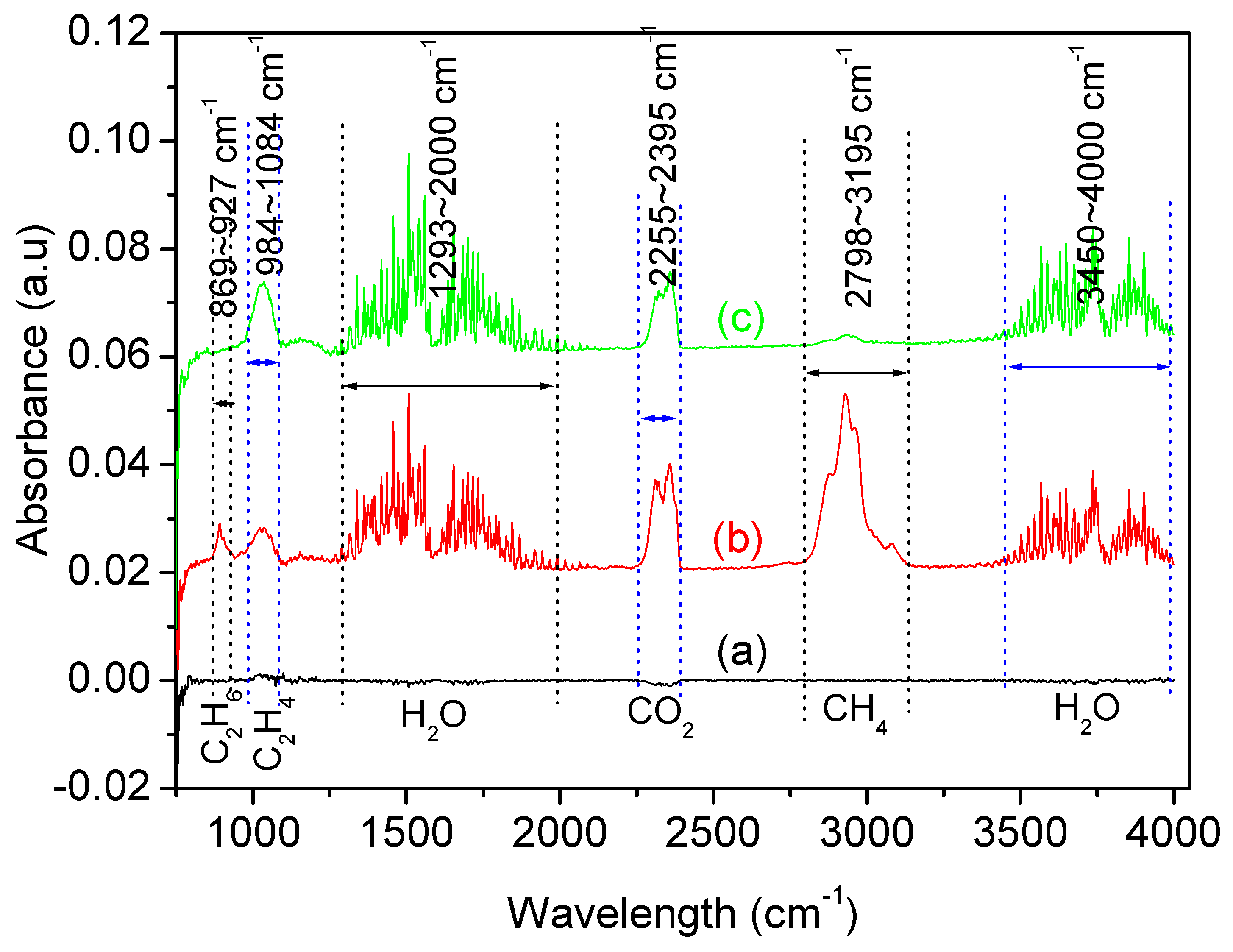
FTIR is widely used to characterised volatile species evolving during pyrolysis, and Figure 4 demonstrates the gaseous molecule during thermal transformation of latex. At a lower temperature of 50 °C (Figure 4a), there was no significant gas evolved. At the maximum decomposition of latex at 387 °C (TGA Figure 3), the gas species were detected at the FTIR spectrum peak with 1293 cm−1–2000 cm−1, and 3450–4000 cm−1 is the characteristic peak of water (moisture in source material) that appears due to the O-H stretching, which also found in biomass and refuse-derived fuel (RDF) waste reported by other researchers. The peak appeared ranging from 2255–2395 cm−1 due to the C = O stretching for CO2 species. At 387 °C, the small peak appeared at 2180 cm−1, ranging from 2168 cm−1–2210 cm−1 due to the C-O stretching for the CO molecule. The peak at absorption wavelength from 869–927 cm−1 was due to disubstituted alkane gas (CH3=CH3), and the peak appeared at 1025 cm−1 in the region 984–1084 cm−1 for alkene (CH2=CH2) [57,58]. At a higher temperature (1000 °C) the detection peak for ethane (CH3-CH3) and CO disappeared, a low amount CH4 was detected, and only a significant amount CO2 gas was produced [59,60,61].
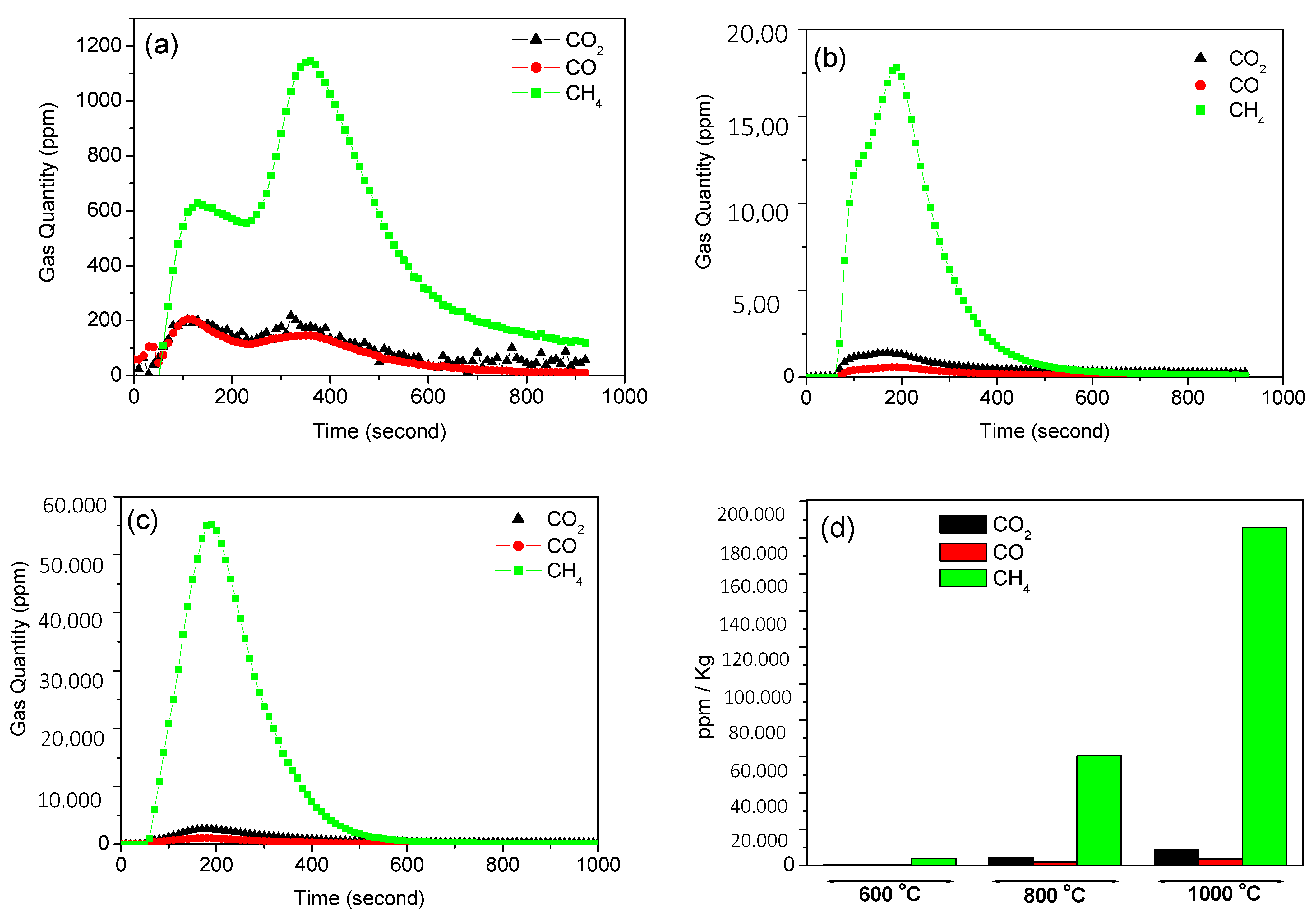
The quantitative measurement of three gases (CO, CO2, and CH4) generated during the thermal transformation (600 °C–1000 °C) of latex in the horizontal tube furnace was also recorded continuously using an IR gas analyser under inert environment. The results of the gas analysis have been summarised in Table 1. Volumes of gases released at three representative temperatures are shown in Figure 5. At 600 °C, the volume of released CH4 gas was 5.5 and 7.5 times higher than that of CO2 and CO respectively. In addition, CH4 produced at 800 °C was also found higher by 13.1 and 31.3 than CO2 and CO respectively. Furthermore, latex was introduced at 1000 °C, and interestingly, green gas (CH4) production was detected 21.1 and 51.6 times higher than that of CO2 and CO respectively. The comparative result (Figure 5d) illustrates that negligible amounts of CO and CO2 were produced compared to CH4, and the rapid release of CH4 gas was produced at higher temperatures (1000 °C) which is 3.1 and 49.0 times higher than CH4 produced at 800 °C and 600 °C respectively. These results illustrate that bonding of latex degrades into small molecule gases at higher temperatures, which leads to gases like CH4 and H2 being produced at higher temperatures.
After quantitative gas analysis (15 min heat treatment in a horizontal tube furnace) the residual black carbon like materials were characterised by XPS, Raman spectroscopy, SEM, and TEM.
XPS analysis (Figure 6) was performed to understand the main components in the materials which illustrated that all products after selective thermal transformation at different temperatures (C-600, C-800, C−1000) contain carbon and other elements. In detail, C, Na, Zn, O, N, K, S, Si were found at binding energy 284.8 Ev–290.9 eV, 1072.2–1072.4 eV, 1021.9–1022.3 eV, 531.5–532.9 eV, 398.8–402.1 eV, 293.4–293.6 eV, 161.7–161.9 eV, and 102.9–103.3 eV respectively [62,63,64,65].
Table 2 shows the chemical composition of prepared materials and illustrates that all samples contained carbon as well as the same type of other elements. In addition, carbon percentage increased significantly at higher temperatures, while the percentage of S dramatically dropped at 1000 °C.
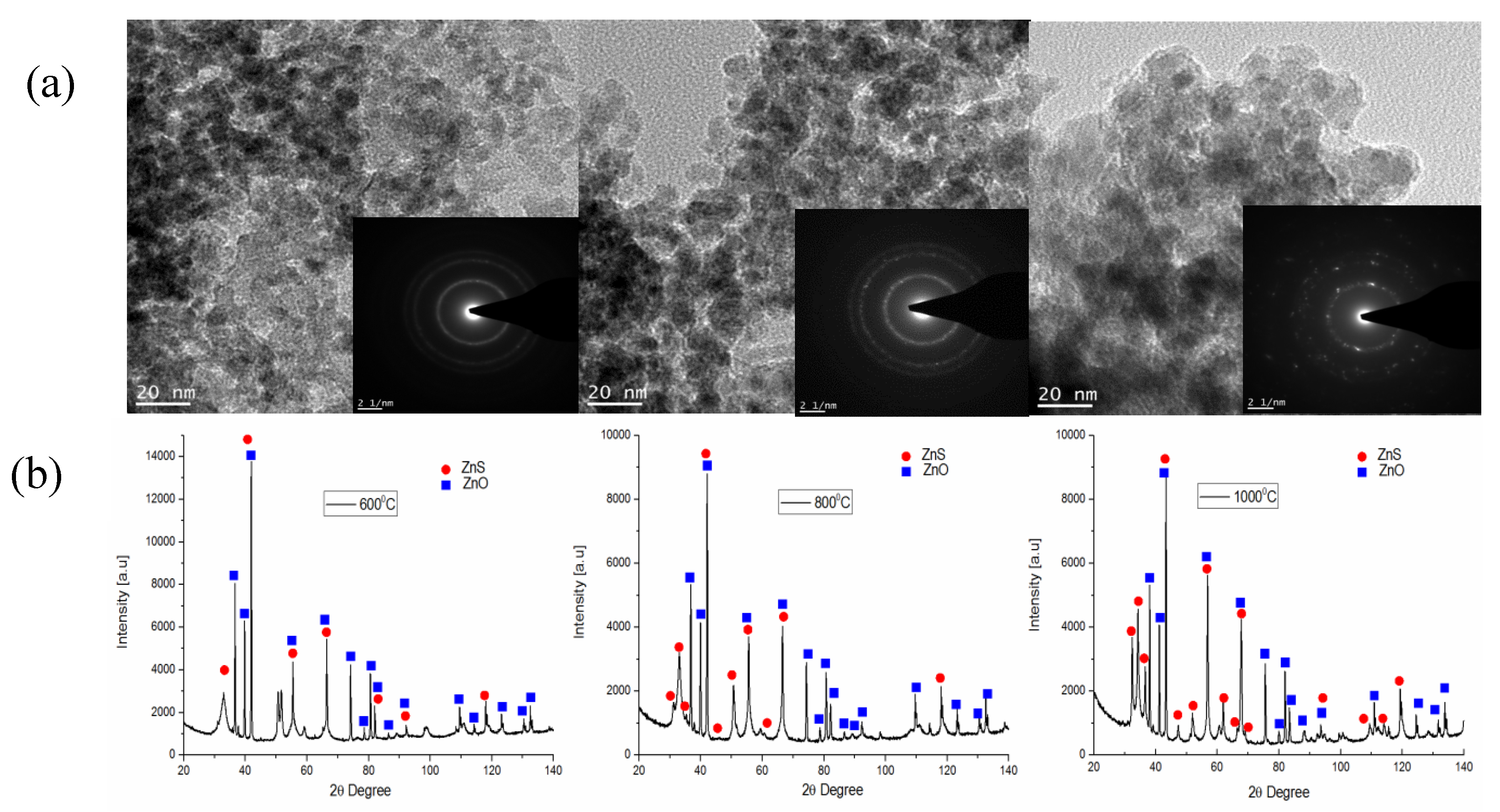
The microstructures of the heat-treated samples were investigated by transmission electron microscopy (TEM). The results (Figure 7) clearly indicate that the nanomaterials phase constituent after heat treatment at different temperatures and the structure of nano particles became more ordered by increasing the temperature. The phase separation was not significantly observed at lower temperatures, but at a higher temperature (1000 °C) discrete lights within the selected area electron diffraction (SAED) ring pattern reveals the phase separation of carbon and metals which complements the XRD results. The selected area electron diffraction (SAED) pattern shown in Figure 7a with clear rings is indicative of the polycrystalline structure of nanoparticles wrapped by a carbon layer. The X-ray diffraction (XRD) peaks and SAED pattern revealed that the nano particles are rich in ZnS and ZnO and are embedded within the (111), (220), and (311) planes of carbon matrix.
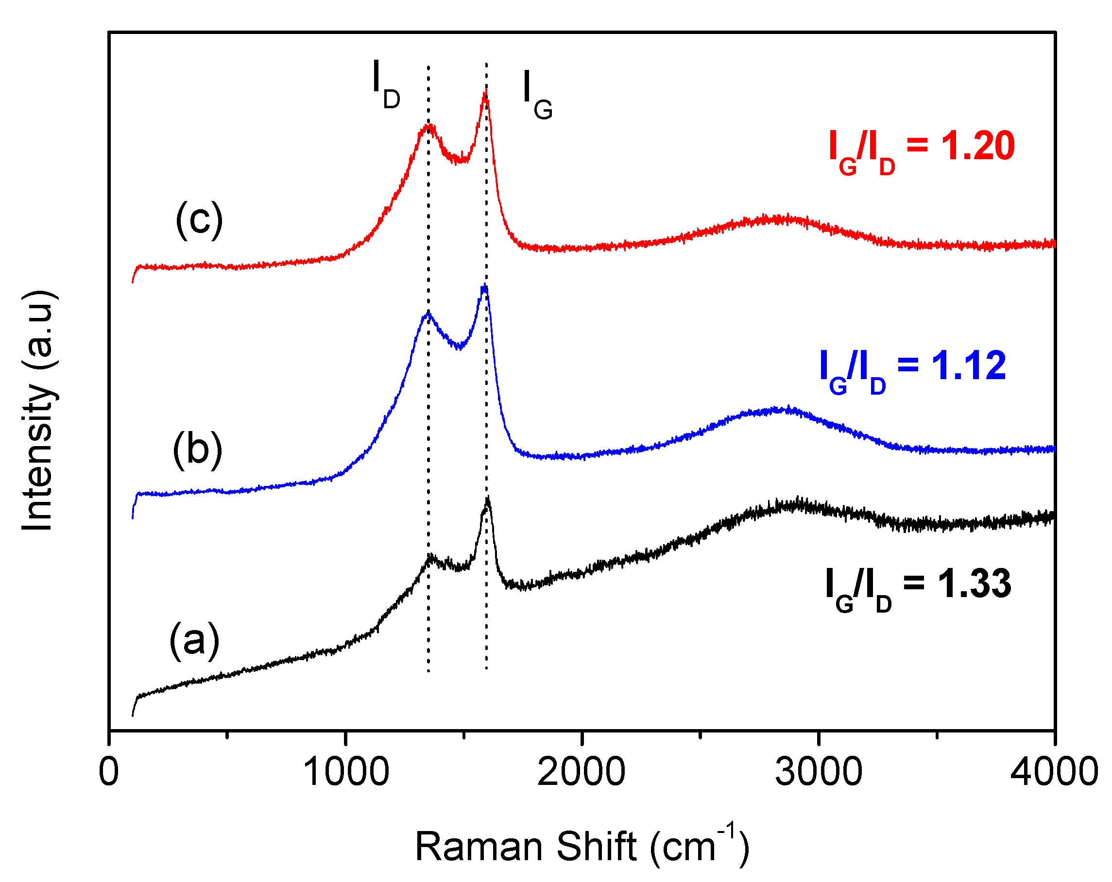
To determine the structure of the carbon phase, residual carbons were also analysed by Raman spectroscopy, where the scattering process includes contributions from various phonon vibration modes of materials. The spectrum from latex carbon residues after excitation with 514 nm laser light is shown in Figure 8. The spectrums peak at position 1359, 1346, and 1354 cm−1 for C-600, C-800, and C−1000 respectively, known as D (defect) band which feature representing disorder in graphitic structures; and the peak at 1599, 1584, and 1552 cm−1 for C-600, C-800, and C−1000 respectively, known as G (graphite) band, represents highly ordered graphitic structure [11,66,67]. The relative intensity ratio of IG/ID bands was determined from peak intensity, which can be used to determine the extent of disorder/or the degree of graphitisation in the carbon structure [66]. These were determined to be 1.33, 1.12, and 1.20 for C-600, C-800, and C−1000 C respectively; this result indicates extensive disorder and poor graphitisation in the carbon structure. Both Raman and X-ray diffraction results are in good agreement and indicate these materials to be disordered carbons.
Heteroatom carbon materials (N, B, P, S) are highly demanded materials for different application in composites [62,63,64,65,66]. There were various types of materials used for making carbon nanomaterials incorporated with different elements. For example, N-doped carbon materials were prepared by direct thermal treatment of carbons with N-containing precursors activated carbon [11,67], carbon nanotubes (CNTs) [68], graphene oxide (GO), and reduced graphene oxide (RGO) [11]. The nitrogen-containing precursors can be ammonia [68,69], urea [70], melamine [71], cyanamide [72], dicyandiamide [73], polyaniline (PANI) and polypyrrole (PPy) [74], and metal–organic frameworks (MOFs) [75]. On the other hand, S-doped carbon synthesised by using many precursors, mainly: thiophenemethanol [76], tetra(thiophene-2-ylmethoxy)silane [77], microporous poly(1,3,5-tris(thienyl)benzene) network (PTTB) [78], thiophene [78], H2S/graphene oxide [67], benzyl disulphide (BDS) [79], K2SO4 or Na2S2O3/glucose [80], sulphur/graphite [81], etc. These S and N-doped carbons can be used as electrodes for supercapacitors [82], batteries [62], and fuel cells [79]. Synthesis of co-doped carbon materials from waste materials have not yet been reported.
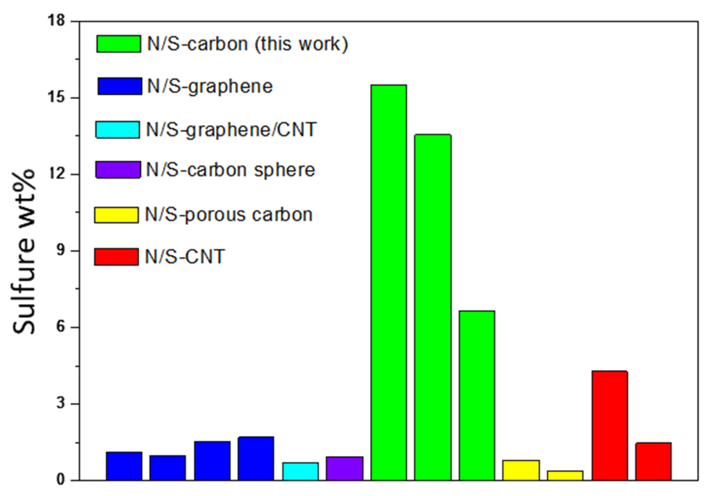
A comparison study of our results and previous literature reported results based on carbon nanomaterials with different elements is shown in Table 3. Wu et al. [21] reported a two step synthesis method using the precursors 5-amino−1,3,4-thiadiazole-2-thiol and graphene oxide, with the final product doped graphene which composed of 0.48–1.8% N and 0.58–1.1% S. In this process (hydrothermal and pyrolysis) synthesise time required 22 h to get to the final product. Similarly, doped graphene (1.85% N and 0.99% S) was synthesised from cysteine precursor in three step process for a total reaction time of 29 h [23]. In addition, doped graphene (1.3–1.5% S) and doped (2.4–4.6% N and 1.2–1.7% S) graphene were prepared in a single step process (thermal treatment for 1h) from the precursors benzyl disulphide (+graphene oxide) and NH3-H2S gas (+graphene-silica) respectively [24,25]. However, urea and thiourea (GO + CNT) resulted in doped (2.4–4.6% N and 0.67–0.71% S) graphene/carbon nanotube via hydrothermal process at 180 °C for 12 h [26]. Table 3 shows that our synthesised carbon materials are much better than reported doped graphene material in terms of S-doping (6.65–15.49%), reaction time (only 15 min), and remarkable N-doping (1.29% to 2.04%). Figure 9 compares these rations for different materials.
Moreover, N/S-codoped carbon spheres (0.95% S and 2.85% N) were synthesised by Kang and co-worker, via these precursors (D-glucose, L-cystenine, KOH, S-powder) in a three step process (total reaction time = 37 h) towards its application in Li-S battery [27]. A similar application (Li-S battery) for S/N-doped carbon fibre synthesised via a three step process for 63 h, was reported by Lan et al. [29]. However, catalytic oxidation activity of S/N-codoped porous carbon (2% N and 0.8% S) to make small organic molecules was synthesised in a single step (pyrolysis of cysteine for 2h at 800 °C) reported by Yao et al. [28]. Besides, S/N-doped porous carbon prepared by a two step process with a total reaction time of 171 h (used PPy precursors, KOH, S powder), performed well as electrode material for supercapacitors and fuel cells [30]. All these results illustrate that there is a great potential for using waste as input for producing doped carbon.
On the other hand, carbon nanotube (0.18% N and 3.02–4.29% N) from toluenethiol and sulphur precursors via a two-step process (hydrothermal at 180 °C and thermal treatment at 900 °C) for 9.5 h, towards its application for fuel cells. S/N-doped carbon nanotube (1–3% N and 0.6–1.5% S) prepared in a single step via pyrolysis of urea, thiourea and CNT at 800 °C for 1 h could be used in a similar application [10]. These results emphasize that this new approach for synthesised carbon materials can be considered as an alternative approach for producing high-value-added materials from waste. Produced carbon and other additives can be used as the filler in polymeric composite because of its exceptional fire resistance properties. Also produced methane can be used for producing green hydrogen or it can be used as a source of energy on its own. More study on the properties of produced product is needed to identify the best process for producing these materials and the best application for them.
4. Conclusions
The possibility of selective thermal transformation of waste latex to directly transform waste mattress component (latex) to value-added gas as well as carbon nanomaterials has been investigated. The waste latex can be suggested as a remarkable material to produce green gases, especially methane. The quantitative gas analysis suggested that temperature had significant effect on the production of CH4 gas. A magnificent amount of CH4 gas (18,5760 ppm/Kg) was produced at the higher temperature of 1000 °C, which is much greater than that produced at 800 °C and 600 °C, by factor 3 and 49 respectively. The resultant carbon residue was characterised by XPS, TEM, XRD, and Raman, suggesting the synthesis of value-added carbon materials with 7–15% S and 1–2% N. According to the literature review, our synthesis method can be considered as an alternative approach for synthesis of carbon after further investigation of the produced material. These results suggest the following possibilities for nanomaterials and should be further researched: (1) waste soft mattress materials (latex) can be recycled to produce green gas (CH4) production; (2) carbon materials synthesis by direct carbonisation of latex; and (3) produced carbon can be used as a valuable material for other applications after full characterisation and investigation of the produced materials.
Author Contributions
E.H. performed the experiments and wrote the first draft of the manuscript, F.P. designed the experiment and analyzed the data and modified and wrote the manuscript, N.G. analysed the carbon structure and its properties and edited the manuscript, R.H. performed the T.E.M. and SEM analysis, V.S. supervised the study and edited the manuscript. All authors have read and agreed to the published version of the manuscript.
Funding
Australian Research Council’s Industrial Transformation Research Hub funding scheme (project IH130200025).
Acknowledgments
This research was supported under Australian Research Council’s Industrial Transformation Research Hub funding scheme (project IH130200025). We gratefully acknowledge the technical support provided by the Analytical Centre in the UNSW Australia.
Conflicts of Interest
The authors declare no conflict of interest.
References and Note
- Paraknowitsch, J.P.; Thomas, A. Doping carbons beyond nitrogen: An overview of advanced heteroatom doped carbons with boron, sulphur and phosphorus for energy applications. Energy Environ. Sci. 2013, 6, 2839–2855. [Google Scholar] [CrossRef] [Green Version]
- Peng, H.-J.; Zhang, Q. Designing host materials for sulfur cathodes: From physical confinement to surface chemistry. Angew. Chem. Int. Ed. 2015, 54, 11018–11020. [Google Scholar] [CrossRef] [PubMed]
- See, K.A.; Jun, Y.-S.; Gerbec, J.A.; Sprafke, J.K.; Wudl, F.; Stucky, G.D.; Seshadri, R. Sulfur-functionalized mesoporous carbons as sulfur hosts in Li-S batteries: Increasing the affinity of polysulfide intermediates to enhance performance. ACS Appl. Mater. Interfaces 2014, 6, 10908–10916. [Google Scholar] [CrossRef] [PubMed]
- Yang, Z.; Dai, Y.; Wang, S.; Cheng, H.; Yu, J. In situ incorporation of a S, N doped carbon/sulfur composite for lithium sulfur batteries. Rsc Adv. 2015, 5, 78017–78025. [Google Scholar] [CrossRef]
- Zhou, G.; Paek, E.; Hwang, G.S.; Manthiram, A. Long-life Li/polysulphide batteries with high sulphur loading enabled by lightweight three-dimensional nitrogen/sulphur-codoped graphene sponge. Nat. Commun. 2015, 6, 7760. [Google Scholar] [CrossRef] [PubMed]
- Zhang, C.; Mahmood, N.; Yin, H.; Liu, F.; Hou, Y. Synthesis of phosphorus-doped graphene and its multifunctional applications for oxygen reduction reaction and lithium ion batteries. Adv. Mater. 2013, 25, 4932–4937. [Google Scholar] [CrossRef] [PubMed]
- Liu, H.; Liu, Y.; Zhu, D.J. Chemical doping of grapheme. Mater. Chem. 2011, 21, 3335–3345. [Google Scholar] [CrossRef]
- Shen, W.; Fan, W.J. Electrochemical performances of hydrothermal tannin-based carbons doped with nitrogen. Mater. Chem. A 2013, 1, 999–1013. [Google Scholar] [CrossRef]
- Jeon, J.-W.; Sharma, R.; Meduri, P.; Arey, B.W.; Schaef, H.T.; Lutkenhaus, J.L.; Lemmon, J.P.; Thallapally, P.K.; Nandasiri, M.I.; McGrail, B.P.; et al. In Situ One-Step Synthesis of Hierarchical Nitrogen-Doped Porous Carbon for High-Performance Supercapacitors. ACS Appl. Mater. Interfaces 2014, 6, 7214–7222. [Google Scholar] [CrossRef] [PubMed]
- Zhang, C.; Hao, R.; Liao, H.; Hou, Y. Synthesis of amino-functionalized graphene as metal-free catalyst and exploration of the roles of various nitrogen states in oxygen reduction reaction. Nano Energy 2013, 2, 88–97. [Google Scholar] [CrossRef]
- Wang, H.; Maiyalagan, T.; Wang, X. Review on recent progress in nitrogen-doped Graphene: Synthesis, characterization, and its potential applications. ACS Catal. 2012, 2, 781–794. [Google Scholar] [CrossRef]
- Kicinski, W.; Szala, M.; Bystrzejewski, M. Sulfur-doped porous carbons: Synthesis and applications. Carbon 2014, 68, 1–32. [Google Scholar] [CrossRef]
- Yang, Z.; Yao, Z.; Li, G.; Fang, G.; Nie, H.; Liu, Z.; Zhou, X.; Chen, X.; Huang, S. Sulfur-doped graphene as an efficient metal-free cathode catalyst for oxygen reduction. ACS Nano. 2012, 6, 205–211. [Google Scholar] [CrossRef]
- Zhang, L.; Niu, J.; Li, M.; Xia, Z.J. Catalytic Mechanisms of sulfur-doped graphene as efficient oxygen reduction reaction catalysts for fuel cells. Phys. Chem. C. 2014, 118, 3545–3553. [Google Scholar]
- Liang, J.; Jiao, Y.; Jaroniec, M.; Qiao, S.Z. Sulfur and nitrogen dual-doped mesoporous graphene electrocatalyst for oxygen reduction with synergistically enhanced performance. Angew. Chem. Int. Ed. 2012, 51, 11496–11500. [Google Scholar] [CrossRef]
- Li, J.; Chen, Y.; Tang, Y.; Li, S.; Dong, H.; Li, K.; Han, M.; Lan, Y.-Q.; Bao, J.; Dai, Z.J. Metal–organic framework templated nitrogen and sulfur co-doped porous carbons as highly efficient metal-free electrocatalysts for oxygen reduction reactions. Mater. Chem. A 2014, 2, 6316–6319. [Google Scholar] [CrossRef]
- Jiang, X.; Li, C.; Chi, Y.; Yan, J. TG-FTIR study on urea-formaldehyde resin residue during pyrolysis and combustion. J. Hazard. Mater. 2010, 173, 205–210. [Google Scholar] [CrossRef]
- Giuntoli, J.; De Jong, W.; Arvelakis, S.; Spliethoff, H.; Verkooijen, A. Quantitative and kinetic TG-FTIR study of biomass residue pyrolysis: Dry distiller’s grains with solubles (DDGS) and chicken manure. J. Anal. Appl. Pyrolysis. 2009, 85, 301–312. [Google Scholar] [CrossRef]
- Wei, J.; Zhou, D.; Sun, Z.; Deng, Y.; Xia, Y.; Zhao, D. A controllable synthesis of rich nitrogen-doped ordered mesoporous carbon for co2 capture and supercapacitors. Adv. Funct. Mater. 2013, 23, 2322. [Google Scholar] [CrossRef]
- Li, L.; Liu, E.; Li, J.; Yang, Y.; Shen, H.; Huang, Z.; Xiang, X.; Li, W.J. A doped activated carbon prepared from polyaniline for high performance supercapacitors. Power Sources 2010, 195, 1516. [Google Scholar] [CrossRef]
- Zhou, Y.; Ma, R.; Candelaria, S.L.; Wang, J.; Qian, L.E.; Uchaker, P.; Li, Y.; Chen, G.C. Phosphorus/sulfur Co-doped porous carbon with enhanced specific capacitance for supercapacitor and improved catalytic activity for oxygen reduction reaction. J. Power Sources 2016, 314, 39–48. [Google Scholar] [CrossRef] [Green Version]
- Wu, M.; Dou, Z.J.C.; Cui, L. Nitrogen and sulfur co-doped graphene aerogels as an efficient metal-free catalyst for oxygen reduction reaction in an alkaline solution. Rsc Adv. 2016, 6, 22781. [Google Scholar] [CrossRef]
- Domínguez, C.; Pérez-Alonso, F.J.S.; Al-Thabaiti, A.; Basahel, S.N.; Obaid, A.Y.; Alyoubi, A.O.; Fuente, J.L.G.; Rojas, S. Effect of N and S co-doping of multiwalled carbon nanotubes for the oxygen reduction. Electrochim. Acta 2015, 157, 158–165. [Google Scholar] [CrossRef]
- Pan, F.; Duan, Y.; Zhang, X.; Zhang, J. A facile synthesis of nitrogen/sulfur co-doped graphene for the oxygen reduction reaction. J. ChemCatChem 2016, 8, 163–170. [Google Scholar] [CrossRef]
- Zhu, H.; Yan, J.; Jiang, X.; Lai, Y.; Cen, K. Study on pyrolysis of typical medical waste materials by using TG-FTIR analysis. J. Hazard. Mater. 2008, 153, 670–676. [Google Scholar] [CrossRef]
- Yang, S.; Zhi, L.; Tang, K.; Feng, X.; Maier, J.; Müllen, K. Efficient Synthesis of Heteroatom (N or S)-Doped Graphene Based on Ultrathin Graphene Oxide-Porous Silica Sheets for Oxygen Reduction Reactions. Adv. Funct. Mater. 2012, 22, 3634–3640. [Google Scholar] [CrossRef]
- Zhao, J.; Liu, Y.; Quan, X.; Chen, S.; Zhao, H.; Yu, H. Nitrogen and sulfur co-doped graphene/carbon nanotube as metal-free electrocatalyst for oxygen evolution reaction: The enhanced performance by sulfur doping. Electrochim. Acta 2016, 204, 169–175. [Google Scholar] [CrossRef]
- Niu, S.; Lv, W.; Zhou, G.; He, Y.; Li, B.; Yang, Q.-H.; Kang, F. N and S co-doped porous carbon spheres prepared using l-cysteine as a dual functional agent for high-performance lithium–sulfur batteries. Chem. Commun. 2015, 51, 17720–17723. [Google Scholar] [CrossRef]
- Gao, W.; Feng, X.; Zhang, T.; Huang, H.; Li, J.; Song, W. One-Step Pyrolytic Synthesis of Nitrogen and Sulfur Dual-Doped Porous Carbon with High Catalytic Activity and Good Accessibility to Small Biomolecules. Acs Appl. Mater. Interfaces 2014, 6, 19109–19117. [Google Scholar] [CrossRef]
- Zhou, L.; Lin, X.; Huang, T.; Yu, A. Nitrogen-doped porous carbon nanofiber webs/sulfur composites as cathode materials for lithium-sulfur batteries. Electrochim. Acta 2014, 116, 210–216. [Google Scholar] [CrossRef]
- Shi, Q.; Peng, F.; Liao, S.; Wang, H.; Yu, H.; Liu, Z.; Zhang, B.; Su, D.J. Sulfur and nitrogen co-doped carbon nanotubes for enhancing electrochemical oxygen reduction activity in acidic and alkaline media. Mater. Chem. A 2013, 1, 14853–14857. [Google Scholar] [CrossRef]
- Blue Environment and Randell Environment Consulting. Waste Generation and Resource Recovery in Australia; Australian National Waste Reporting; Blue Environment and Randell Environment Consulting: Melbourne, Australia, 2013. [Google Scholar]
- (a) Waste Authority, Government of Western Australia, EMRC (2009). Available online: https://www.parliament.wa.gov.au/publications/tabledpapers.nsf/displaypaper/3811675a172c5a2337572bdac825767b000c60ba/$file/waste+authority+ar+2008-9.pdf. (b) Mattress Recycling Project Expansion: Final Report; Available online: https://www.environment.gov.au/system/files/resources/0a517ed7-74cb-418b-9319-7624491e4921/files/casestudy-softlanding.pdf (accessed on 4 November 2020).
- Georgouras, M. Soft Landing: Social Return on Investment Study; Centre for Social Impact: Sidney, Australia, 1992. [Google Scholar]
- Kemp, A.R. Composition and structure of heave latex. Ind. Eng. Chem. 1938, 30, 154–158. [Google Scholar] [CrossRef]
- Singh, S.; Wu, C.; Williams, J.P.T. Pyrolysis of waste materials using TGA-MS and TGA-FTIR as complementary characterisation techniques. Analyt. Appl. Pyrolys. 2012, 94, 99–107. [Google Scholar] [CrossRef]
- Tao, L.; Zhao, G.; Qian, J.; Qin, Y. TG-FTIR characterisation of pyrolysis of waste mixtures of paint and tar slag. J. Hazard. Mater. 2010, 175, 754–761. [Google Scholar] [CrossRef]
- Han, L.; Wang, Q.; Ma, Q.; Yu, C.; Luo, Z.; Cen, K. Influence of CaO additives on wheat-straw pyrolysis as determined by TG-FTIR analysis. J. Anal. Appl. Pyrolysis. 2010, 88, 199–206. [Google Scholar] [CrossRef]
- Fu, P.; Hu, S.; Xiang, J.; Li, P.; Huang, D.; Jiang, L.; Zhang, A.; Zhang, J. FTIR study of pyrolysis products evolving from typical agricultural residues. J. Anal. Appl. Pyrolysis. 2010, 88, 117–123. [Google Scholar] [CrossRef]
- Hardy, A.; Van Werde, K.; Vanhoyland, G.; Van Bael, M.; Mullens, J.; Van Poucke, L.; Van Bael, M.K. Study of the decomposition of an aqueous metal–chelate gel precursor for (Bi,La)4Ti3O12 by means of TGA–FTIR, TGA–MS and HT-DRIFT. Acta 2003, 397, 143–153. [Google Scholar] [CrossRef]
- Ferrasse, J.-H.; Chávez, S.; Arlabosse, P.; Dupuy, N. Chemometrics as a tool for the analysis of evolved gas during the thermal treatment of sewage sludge using coupled TG–FTIR. Thermochim. Acta 2003, 404, 97–108. [Google Scholar] [CrossRef] [Green Version]
- Marcilla, A.; Menargues, A.G.S. TGA/FTIR study of the catalytic pyrolysis of ethylene–vinyl acetate co-polymers in the presence of MCM-41. Polym. Degrad. Stab. 2005, 89, 145–152. [Google Scholar] [CrossRef]
- Yang, H.; Yan, R.; Liang, T.D.; Chen, H.; Zheng, C. Pyrolysis of palm oil wastes for biofuel production. J. Energy Environ. 2006, 702, 315–323. [Google Scholar]
- Yang, H.; Yan, R.; Chen, H.; Lee, D.H.; Zheng, C. Characteristics of hemicellulose, cellulose and lignin pyrolysis. Fuel 2007, 86, 1781–1788. [Google Scholar] [CrossRef]
- Jang, B.N.; Wilkie, C.A. A TGA/FTIR and mass spectral study on the thermal degradation of bisphenol A polycarbonate. Polym. Degrad. Stab. 2004, 86, 419–430. [Google Scholar] [CrossRef] [Green Version]
- Tudorachi, N.; Chiriac, A.P. TGA/FTIR/MS study on thermal decomposition of poly(succinimide) and sodium poly(aspartate). Polym. Test. 2011, 30, 397–407. [Google Scholar] [CrossRef]
- Williams, P.T.; Besler, S. Pyrolysis-thermogravimetric analysis of tyres and tyre components. Fuel 1995, 74, 1277–1283. [Google Scholar] [CrossRef]
- García, A.N.; Emarcilla, A.; Font, R. Thermogravimetric kinetic study of the pyrolysis of municipal solid waste. Acta 1995, 254, 277–304. [Google Scholar] [CrossRef]
- Buah, W.K.; Cunliffe, A.M.; Williams, P.T. Characterisation of products from the pyrolysis of municipal solid waste energy. Trans. IChemE Part B Process. Saf. Environ. Protec. 2007, 85, 450–457. [Google Scholar] [CrossRef]
- Sricharoenchaikul, V.; Atong, D. Thermal decomposition study on Jatropha curcas L. waste using TGA and fixed bed reactor. J. Anal. Appl. Pyrolysis 2009, 85, 155–162. [Google Scholar] [CrossRef]
- Duan, H.B.; Li, J.H. Thermal degradation behaviour of waste video cards using thermogravimetric analysis and pyrolysis gas chromatography/mass spectrometry techniques. J. Air Waste Manag. Assoc. 2010, 60, 540–547. [Google Scholar] [CrossRef]
- Na, D.; Yu-Feng, Z.; Yan, W. Thermogravimetric analysis and kinetic study of representative medical waste composition. Waste Manag. 2008, 28, 1572–1580. [Google Scholar]
- Yang, H.; Yan, R.; Chin, T.; Liang, D.T.; Chen, A.H.; Zheng, C. Thermogravimetric Analysis—Fourier Transform Infrared Analysis of Palm Oil Waste Pyrolysis. Energy Fuels 2004, 18, 1814–1821. [Google Scholar] [CrossRef]
- Giuntoli, J.; Arvelakis, S.; Spliethoff, H.; De Jong, W.; Verkooijen, A.H.M. Quantitative and Kinetic Thermogravimetric Fourier Transform Infrared (TG-FTIR) Study of Pyrolysis of Agricultural Residues: Influence of Different Pretreatments. Energy Fuels 2009, 23, 5695–5706. [Google Scholar] [CrossRef]
- Ischia, M.; Perazzolli, C.; Maschio, R.D.; Campostrini, R. Pyrolysis study of sewage sludge by TG-MS and TG-GC-MS coupled analyses. J. Anal. Calorim. 2006, 87, 567–574. [Google Scholar] [CrossRef]
- Zhou, Q.; Zhao, Z.; Zhang, Y.; Meng, B.; Zhou, A.; Qiu, J. Graphene Sheets from Graphitized Anthracite Coal: Preparation, Decoration, and Application. Energy Fuels 2012, 26, 5186–5192. [Google Scholar] [CrossRef]
- Orvis, A.L.; Allwein, S. Gas Sampling and Analysis by Fourier Transform Infrared Spectroscopy. In Proceedings of the Fire and Materials 2001 Conference, San Francisco, CA, USA, 22–24 January 2001; Copyright Interscience Communications Ltd.: London, UK, 2001; pp. 433–446. [Google Scholar]
- Filipczak, R.A.; Blake, D.; Speitel, L.; Lyon, R.E.; Williams, J.M.; Gill, W. Development and Testing of a Plastic Smoke Generation Source. In Proceedings of the Fire and Materials 2001 Conference, San Francisco, CA, USA., 22–24 January 2001; Copyright Interscience Communications Ltd.: London, UK, 2001; pp. 93–104. [Google Scholar]
- Sahajwalla, V.; Cayumil, R.; Khanna, R.; Ikram-Ul-Haq, M.; Rajarao, R.; Mukherjee, P.S.; Hill, A.J. Recycling polymer rich waste printed circuit boards at high temperatures: Recovery of value-added carbon resources. Sustain. Met. 2015, 1, 75–84. [Google Scholar] [CrossRef] [Green Version]
- Li, X.; Hayashi, J.-I.; Li, C.-Z. FT-Raman spectroscopic study of the evolution of char structure during the pyrolysis of a Victorian brown coal. Fuel 2006, 85, 1700–1707. [Google Scholar] [CrossRef]
- Sadezky, A.; Muckenhuber, H.; Grothe, H.; Niessner, R.; Pöschl, U. Raman microspectroscopy of soot and related carbonaceous materials: Spectral analysis and structural information. Carbon 2005, 43, 1731–1742. [Google Scholar] [CrossRef]
- Raymundo-Pinero, E.; Cadek, M.; Beguin, F. A high-performance carbon for supercapacitors obtained by carbonization of a seaweed biopolymer. Adv. Funct. Mater. 2009, 19, 1032–1039. [Google Scholar] [CrossRef]
- Xu, B.; Yue, S.F.; Sui, Z.Y.; Zhang, X.T.; Hou, S.S.; Cao, G.P.; Yang, Y.S. What is the choice for supercapacitors: Graphene or graphene oxide? Energy Environ. Sci. 2011, 4, 2826–2830. [Google Scholar] [CrossRef]
- Lee, W.S.V.; Leng, M.; Li, M.; Huang, X.L.; Xuen, J.M. Sulphur-functionalized graphene towards high performance supercapacitor. Nano Energy 2015, 12, 250–257. [Google Scholar] [CrossRef]
- Wen, Y.Y.; Wang, B.; Huang, C.C.; Wang, L.Z.; Hulicova-Jurcakova, D. Synthesis of phosphorus-doped graphene and its wide potential window in aqueous supercapacitors. Chem. Eur. J. 2015, 21, 80–85. [Google Scholar] [CrossRef] [PubMed]
- Yang, Z.B.; Ren, J.; Zhang, Z.T.; Chen, X.L.; Guan, G.Z.; Qiu, L.B.; Zhang, Y.; Peng, H.S. Recent advancement of nanostructured carbon for energy applications. Chem. Rev. 2015, 115, 5159–5223. [Google Scholar] [CrossRef]
- Shen, W.Z.; Fan, W.B. Nitrogen-containing porous carbons: Synthesis and application. J. Mater. Chem. A. 2013, 1, 999–1013. [Google Scholar] [CrossRef]
- Marjanović, G.C.; Pašti, I.; Mentus, S. One-dimensional nitrogen-containing carbon nanostructures. Prog. Mater. Sci. 2015, 69, 61–182. [Google Scholar]
- Li, X.L.; Wang, H.L.; Robinson, J.T.; Sanchez, H.; Diankov, G.; Dai, H.J. Simultaneous Nitrogen Doping and Reduction of Graphene Oxide. J. Am. Chem. Soc. 2009, 131, 15939–15944. [Google Scholar] [CrossRef] [Green Version]
- Pathak, H.; Tewari, A.N.; Sankhyan, S.; Dubey, D.S.; Mina, U.; Singh, V.K.; Jain, N.; Bhatia, A. Direct-seeded rice: Potential, performance and problems—A review. Curr. Adv. Agri. Sci. 2011, 3, 77–88. [Google Scholar]
- Sheng, Z.H.; Shao, L.; Chen, J.J.; Bao, W.J.; Wang, F.B.; Xia, X.H. Catalyst-Free Synthesis of Nitrogen-Doped Graphene via Thermal Annealing Graphite Oxide with Melamine and Its Excellent Electrocatalysis. Acs Nano. 2011, 5, 4350–4358. [Google Scholar] [CrossRef]
- Hou, S.C.; Cai, X.; Wu, H.W.; Yu, X.; Peng, M.; Yan, K.; Zou, D.C. Nitrogen-doped graphene for dye-sensitized solar cells and the role of nitrogen states in triiodide reduction. Energy Environ. Sci. 2013, 6, 3356–3362. [Google Scholar] [CrossRef]
- Choi, C.H.; Chung, M.W.; Park, S.H.; Woo, S.I. Enhanced electrochemical oxygen reduction reaction by restacking of N-doped single graphene layers. Rsc Adv. 2013, 3, 4246–4253. [Google Scholar] [CrossRef]
- Lai, L.F.; Potts, J.R.; Zhan, D.; Wang, L.; Poh, C.K.; Tang, C.H.; Gong, H.; Shen, Z.X.; Lin, J.Y.; Ruoff, R.S. Exploration of the active center structure of nitrogen-doped graphene-based catalysts for oxygen reduction reaction. Energy Environ. Sci. 2012, 5, 7936–7942. [Google Scholar] [CrossRef]
- Shen, Y.M.; Bai, J.F. A new kind CO2/CH4 separation material: Open ended nitrogen doped carbon nanotubes formed by direct pyrolysis of metal organic frameworks. Chem. Commun. 2010, 46, 1308–1310. [Google Scholar] [CrossRef]
- Shin, Y.; Fryxell, G.E.; Um, W.; Parker, K.; Mattigod, S.V.; Skaggs, R. Sulfur-Functionalized Mesoporous Carbon. Adv. Funct. Mater. 2007, 17, 2897–2901. [Google Scholar] [CrossRef]
- Böttger-Hiller, F.; Mehner, A.; Anders, S.; Kroll, L.; Cox, G.; Simond, F. Sulphur-doped porous carbon from a thiophene-based twin monomer. Chem. Commun. 2012, 48, 10568–10570. [Google Scholar] [CrossRef]
- Paraknowitsch, J.P.; Thomas, A.; Schmidt, J. Microporous sulfur-doped carbon from thienyl-based polymer network precursors. Chem. Commun. 2011, 47, 8283–8285. [Google Scholar] [CrossRef] [PubMed] [Green Version]
- Wang, H.; Bo, X.; Zhang, Y. Sulfur-doped ordered mesoporous carbon with high electrocatalytic activity for oxygen reduction. Electroch. Acta 2013, 108, 404–411. [Google Scholar] [CrossRef]
- Liu, X.; Antonietti, M. Moderating black powder chemistry for the synthesis of doped and highly porous graphene nanoplatelets and their use in electrocatalysis. Adv. Mater. 2013, 25, 6284–6290. [Google Scholar] [CrossRef]
- Jeon, I.-Y.; Zhang, S.; Zhang, L.; Choi, H.-J.; Seo, J.-M.; Xia, Z. Edge-selectively sulfurized graphene nanoplatelets as efficient metal-free electrocatalysts for oxygen reduction reaction: The electron spin effect. Adv. Mater. 2013, 25, 6138–6145. [Google Scholar] [CrossRef] [PubMed]
- Hao, L.; Luo, B.; Li, X.; Jin, M.; Fang, Y.; Tang, Z.; Jia, Y.; Liang, M.; Thomas, A.; Yang, J.; et al. Graphenal Polymers for Energy Storage Studies. Energy Environ. Sci. 2012, 5, 9747–9751. [Google Scholar] [CrossRef] [Green Version]
Figure 1.
Low and high magnification SEM images of latex.

Figure 2.
(a) XPS spectra of latex, (b) deconvoluted C1s region of X-ray photoelectron spectra for latex.
Figure 2.
(a) XPS spectra of latex, (b) deconvoluted C1s region of X-ray photoelectron spectra for latex.
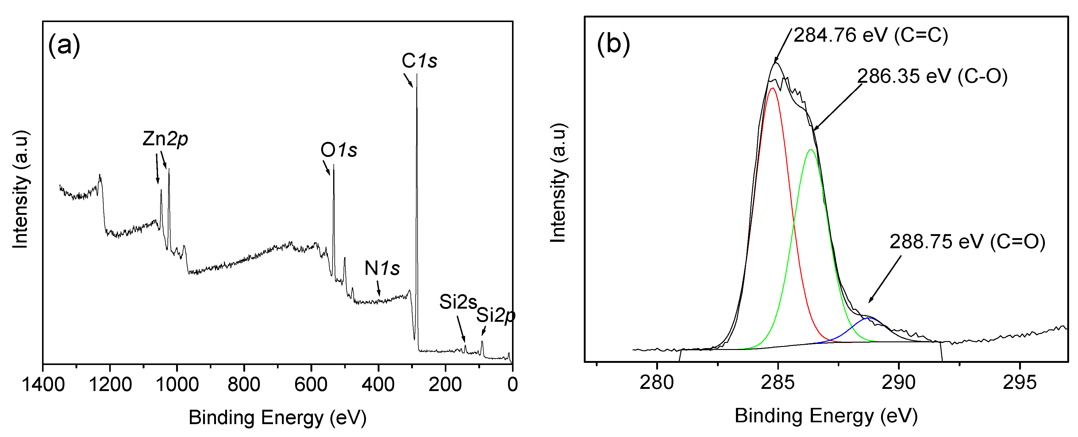
Figure 3.
Thermogravimetric analysis of latex at ramping rate of 20 °C/min under nitrogen flow.

Figure 4.
The 3D infrared spectrum of evolved gases during the pyrolysis of polymeric waste latex between 50 and 1000 °C at a heating rate of 20 °C/min: (a) 50 °C, (b) 387 °C, (c) 1000 °C.
Figure 4.
The 3D infrared spectrum of evolved gases during the pyrolysis of polymeric waste latex between 50 and 1000 °C at a heating rate of 20 °C/min: (a) 50 °C, (b) 387 °C, (c) 1000 °C.

Figure 5.
Quantitative gas released during heat treatment at preheated horizontal furnace: (a) 600 °C, (b) 800 °C, and (c) 1000 °C; (d) Comparison of gas released (CO, CO2 and CH4) at different temperatures.
Figure 5.
Quantitative gas released during heat treatment at preheated horizontal furnace: (a) 600 °C, (b) 800 °C, and (c) 1000 °C; (d) Comparison of gas released (CO, CO2 and CH4) at different temperatures.

Figure 6.
XPS analysis of carbon residue after selective thermal transformation for 15 min at different temperatures: (a) 600 °C, (b) 800 °C, and (c) 1000 °C.
Figure 6.
XPS analysis of carbon residue after selective thermal transformation for 15 min at different temperatures: (a) 600 °C, (b) 800 °C, and (c) 1000 °C.

Figure 7.
(a) Transmission electron microscopy (TEM) image and selected area electron diffraction (SAED) patterns, (b) XRD pattern of carbon residue after selective thermal transformation for 15 min at 600 °C, 800 °C, and 1000 °C.
Figure 7.
(a) Transmission electron microscopy (TEM) image and selected area electron diffraction (SAED) patterns, (b) XRD pattern of carbon residue after selective thermal transformation for 15 min at 600 °C, 800 °C, and 1000 °C.

Figure 8.
Raman spectra of carbon residue after heat treatment after 15 min at different temperatures: (a) 600 °C, (b) 800 °C, and (c) 1000 °C.
Figure 8.
Raman spectra of carbon residue after heat treatment after 15 min at different temperatures: (a) 600 °C, (b) 800 °C, and (c) 1000 °C.

Figure 9.
Comparison of our synthesised carbon materials with other literature reported carbon materials based on the S-doping percentage.
Figure 9.
Comparison of our synthesised carbon materials with other literature reported carbon materials based on the S-doping percentage.


Table 1.
Quantitative gas analysis during heat treatment of latex at horizontal tube furnace for 15 min at three different temperatures.
Table 1.
Quantitative gas analysis during heat treatment of latex at horizontal tube furnace for 15 min at three different temperatures.
| Temperature (°C) | Type of Gas Produced (ppm/Kg) | Comparative Gas Ratio | |||||
|---|---|---|---|---|---|---|---|
| CO2 | CO | CH4 | CH4/CO | CH4/CO2 | CH41000/CH4800 | CH41000/CH4600 | |
| 600 | 687 | 503 | 3793 | 7.54 | 5.52 | ||
| 800 | 4606 | 1927 | 60380 | 31.34 | 13.10 | 3.07 | 48.97 |
| 1000 | 8780 | 3600 | 185760 | 51.6 | 21.16 | - | - |
Table 2.
Chemical composition of carbon residue after heat treatment of latex in a horizontal tube furnace for 15 min at three different temperatures.
Table 2.
Chemical composition of carbon residue after heat treatment of latex in a horizontal tube furnace for 15 min at three different temperatures.
| Materials | Chemical Composition by XPS Analysis | |||||||
|---|---|---|---|---|---|---|---|---|
| C | O | Na | Zn | Si | K | S | N | |
| C-600 | 41.01 | 20.03 | 1.03 | 14.97 | 3.78 | 1.65 | 15.49 | 2.04 |
| C-800 | 47.88 | 17.95 | 1.4 | 12.84 | 2.66 | 2.24 | 13.55 | 1.48 |
| C−1000 | 56.4 | 19.33 | 2.48 | 7.36 | 3.62 | 2.86 | 6.65 | 1.29 |
Table 3.
Comparative Study with Reported Carbon Materials Based on S-Doping Percentage.
| Precursors | Process | Temperature | Time | Final Product | N % | S% | Ref. |
|---|---|---|---|---|---|---|---|
| Latex | Thermal treatment | 600, 800, 1000 °C | 15 min | S/N-doped carbon | 1.29, 1.48, 2.04 | 6.65, 13.55, 15.49 | This work |
| 5-Amino−1,3,4-thiadiazole-2-thiol (C2H3N3S2), and graphene oxide | 2 step process: Hydrothermal + Pyrolysis | 180 °C for hydrothermal + 600–900 °C for pyrolysis | 20 h + 2 h = 22 h | N/S-codoped graphene | 0.48–1.82 | 0.58–1.12 | 21 |
| NaCl, Cysteine [HO2CCH(NH2)CH2SH] | 3 step process: Freezing + pyrolysis + pyrolysis | −26 °C for freezing + 1st pyrolysis 750 °C + 2nd pyrolysis 1000 °C | 24 h + 2 h + 3 h = 29 h | N/S-codoped graphene | 1.85 | 0.99 | 23 |
| Benzyl disulphide, Graphene Oxide | Thermal anneal | 600 °C–1050 °C | 2 h | S-graphene | − | 1.3–1.53 | 13 |
| NH3 and H2S gas + Graphene-Silica | Thermal treatment | 500–1000 °C | 1 h | N/S-codoped graphene | 2.4–4.6 | 1.2–1.7 | 25 |
| Urea+ thiourea+ GO+ CNT | Hydrothermal | 180 °C | 12 h | N/S-codoped graphene/carbon nanotube | 2.4–4.6 | 0.67–0.71 | 26 |
| D-glucose, L-Cysteine, KOH, Sulfur powder | Hydrothermal + thermal activation + heat treatment | 180 °C for hydrothermal + 800 °C for activation + 155 °C for heat treatment | 24h for hydrothermal + 1 h for theral activation + 12 h for heat treatment = 37 h | N/S-codoped carbon sphere | 2.85 | 0.95 | 27 |
| Sodium Citrate + Cysteine | Pyrolysis | 800 °C | 2 h | N/S-codoped porous carbon | 2% | 0.8 | 28 |
| PPy precursors + KOH + S | Pyrolysis +KOH activation + heat treatment | 600 °C for Pyrolysis + 700 °C for activation + 155 °C for heat treatment | 1h for pyrolysis + 2h for KOH activation + 60h for heat treatment = 63 h | N/S-porous carbon fiber | 14.03 | − | 29 |
| Resorcinol and furaldehyde, phosphorus pentasulfide | Sol gel process + pyrolysis | 80 °C for slogel + 1000 °C for pyrolysis | 7 days for sol gel + 3 h for pyrolysis = 171 h | N/S-porous carbon | 1.3 N | 0.4 | 30 |
| Toluenethiol and sulphur, N-CNT | Hydrothermal + thermal | 180 °C for hydrothermal+ 900 °C for thermal | 5.5 h for hydrothermal + 4 h for thermal = 9.5 h | N/S-CNT | 0.18 | 3.02–4.29 | 20 |
| Urea, thiourea and CNT | Thermal | 800 °C | 1 h | N/S CNT | 1.15–3.43 | 0.62–1.47 | 22 |
Publisher’s Note: MDPI stays neutral with regard to jurisdictional claims in published maps and institutional affiliations. |
© 2020 by the authors. Licensee MDPI, Basel, Switzerland. This article is an open access article distributed under the terms and conditions of the Creative Commons Attribution (CC BY) license (http://creativecommons.org/licenses/by/4.0/).
Share and Cite
MDPI and ACS Style
Haque, E.; Pahlevani, F.; Gorjizadeh, N.; Hossain, R.; Sahajwalla, V. Thermal Transformation of End-of-Life Latex to Valuable Materials. J. Compos. Sci. 2020, 4, 166. https://doi.org/10.3390/jcs4040166
AMA Style
Haque E, Pahlevani F, Gorjizadeh N, Hossain R, Sahajwalla V. Thermal Transformation of End-of-Life Latex to Valuable Materials. Journal of Composites Science. 2020; 4(4):166. https://doi.org/10.3390/jcs4040166
Chicago/Turabian StyleHaque, Enamul, Farshid Pahlevani, Narjes Gorjizadeh, Rumana Hossain, and Veena Sahajwalla. 2020. "Thermal Transformation of End-of-Life Latex to Valuable Materials" Journal of Composites Science 4, no. 4: 166. https://doi.org/10.3390/jcs4040166