Article

Polymeric Composites Based on Carboxymethyl Cellulose Cryogel and Conductive Polymers: Synthesis and Characterization

1
Department of Chemistry & Nanoscience and Technology Research and Application Center, Canakkale Onsekiz Mart University Terzioglu Campus, Canakkale 17100, Turkey
2
Department of Chemistry, Hacettepe University, Beytepe, Ankara 06800, Turkey
3
Department of Chemical and Biomolecular Engineering, University of South Florida, Tampa, FL 33620, USA
4
Department of Ophthalmology, Morsani College of Medicine, University of South Florida, 12901 Bruce B. Downs Blvd, MDC21, Tampa, FL 33612, USA
*
Author to whom correspondence should be addressed.
J. Compos. Sci. 2020, 4(2), 33; https://doi.org/10.3390/jcs4020033
Submission received: 7 March 2020 / Revised: 23 March 2020 / Accepted: 27 March 2020 / Published: 29 March 2020
(This article belongs to the Special Issue Recent Advances in Conductive Polymer Composites)

Abstract

:
In this study, a super porous polymeric network prepared from a natural polymer, carboxymethyl cellulose (CMC), was used as a scaffold in the preparation of conductive polymers such as poly(Aniline) (PANi), poly(Pyrrole) (PPy), and poly(Thiophene) (PTh). CMC–conductive polymer composites were characterized by Fourier transform infrared (FT-IR) spectroscopy, thermogravimetric analysis (TGA) techniques, and conductivity measurements. The highest conductivity was observed as 4.36 × 10⁻⁴ ± 4.63 × 10⁻⁵ S·cm−1 for CMC–PANi cryogel composite. The changes in conductivity of prepared CMC cryogel and its corresponding PAN, PPy, and PTh composites were tested against HCl and NH3 vapor. The changes in conductivity values of CMC cryogel upon HCl and NH3 vapor treatment were found to increase 1.5- and 2-fold, respectively, whereas CMC–PANi composites showed a 143-fold increase in conductivity upon HCl and a 12-fold decrease in conductivity upon NH3 treatment, suggesting the use of natural polymer–conductive polymer composites as sensor for these gases.

1. Introduction

Conductive polymers were first synthesized as a new generation of organic materials in the mid-1970s. Although the electrical and optical properties of conductive polymers are similar to metals and organic semiconductors, they have attracted more attention owing to their properties, such as the ease of synthesis and easier processing than metals [1,2,3]. The synthesis methods for conductive polymers can be divided into two main groups, where the starting material is either a polymer or a monomer. Soluble conductive polymers can be deposited through direct polymer solution spraying, sieve, microcontact printing, probe-based deposition, photolithography, and spin coating. Alternatively, monomers can be polymerized by chemical, electrochemical, or plasma techniques [4,5,6,7]. Conductive polymers are widely used in microelectronics industries including photovoltaic devices, light-emitting diodes, electrochromic screens, sensors, and battery technology [8,9,10]. However, the studies in the 1980s demonstrated that conductive polymers are compatible with many biological molecules, causing a significant increase in the use of polymers for biomedical applications. Many conductive polymers such as poly(Aniline) (PANi) [11,12], poly(Pyrrole) (PPy) [13,14], poly(thiophene) (PTh) [15], and their derivatives [16,17,18] have been reported as cell and tissue compatible, which was supported by in vitro and in vivo studies. In addition, the chemical, physical, and electrical properties of conductive polymers can be adapted to particular needs by modification of antibodies, enzymes, and some other biological molecules [19,20,21,22,23].
Many events in the human body, such as neural communication, embryonic development, tissue repair after injury, and heartbeat, among others, are regulated by electrical signals [24]. The components that are electrically active in the human body are the nervous system, heart, and muscles, respectively [25,26]. While the electric is used during the transmission of information between neurons in the nervous system, the muscle cells in the heart produce heartbeats by generating electrical impulses that lead to muscle contraction circulating throughout the organ [25,26]. Besides, some tissues, such as bone marrow, have been shown to use conductivity to regenerate [27]. In this context, studies on the design of electrically conductive materials for biotechnological and biomedical applications have attracted a great deal of attention [28] Conductive polymers have become prominent candidates for materials that can be used in these biotechnological and biomedical fields such as biosensors [29,30], neural electrodes [31,32], bio-activators [33,34], wound healing and controlled release systems [35,36], and tissue scaffolds [37,38], owing to their electrical behavior and biocompatibility [39]. The utilization of conductive polymers in these applications can be augmented further by preparing conductive polymers within super-porous biocompatible cryogels.
In this study, for the first time, in situ synthesis of conductive polymers within natural polymer CMC cryogels is reported. The synthesis of cryogels from natural carboxymethyl cellulose (CMC) polymer by employing cryopolymerization technique was accomplished. Then, the synthesized CMC cryogel was used as a template for in situ synthesis of conductive polymers, PANi, PPy, and PTh for the first time. The prepared CMC–conductive polymer cryogel composites were characterized by means of Fourier transform infrared (FT-IR), thermogravimetric analysis (TGA), and conductivity measurements employing an electrometer. Moreover, the changes in the conductivity of CMC, CMC–PANi, CMC–PPy, and CMC–PTh cryogel composites were investigated for the detection of HCl and NH3 vapor as potential sensing materials.

2. Materials and Methods

2.1. Materials

Carboxymethyl cellulose sodium (CMC, Mw~250,000, degree of substitution: 1.2, Aldrich, St. Louis, MO, USA), divinyl sulfone (DVS, 98%, Merck, Kenilworth, NJ, USA), aniline (ANi, 99%, Sigma-Aldrich, St. Louis, MO, USA), pyrrole (Py, 98%, Aldrich), thiophene (Th, 99%, Aldrich), ammonium persulfate (APS, 98%, Sigma-Aldrich), Iron (III) chloride (FeCl3, 98%, Fluka), hydrochloric acid (HCl, 37%, VWR Chemicals, Radnor, PA, USA), sodium hydroxide (NaOH, 98.8%, VWR Chemicals), chloroform (CH3Cl, 99%, Riedel de Haen), ethanol (99.8%, Sigma-Aldrich), hydrochloric acid (HCl, 37%, VWR Chemicals), ammonium solution (NH3, 25%, Sigma Aldrich), and double distilled water (DDW, GFL2108) were used as received.

2.2. Synthesis of CMC Cryogel

The synthesis of CMC cryogel was reported earlier [40]. In brief, 0.2 g of CMC was dissolved in 6 mL 0.2 M NaOH under constant stirring at 500 rpm for 4 h at ambient temperature, and then cooled in a freezer about 5 min. Then, DVS crosslinker, with a mole ratio of 100% relative to the CMC repeating unit, was added and quickly pipetted (0.8 cm diameter). The mixture was then placed in a freezer at −18 °C for cryopolymerization reaction for 24 h to complete cryo-crosslinking. Prepared CMC cryogels were cut in similar shapes and washed with DDW for purification. Purified CMC cryogels were dried in a freeze-dryer and stored in closed tubes for further use.

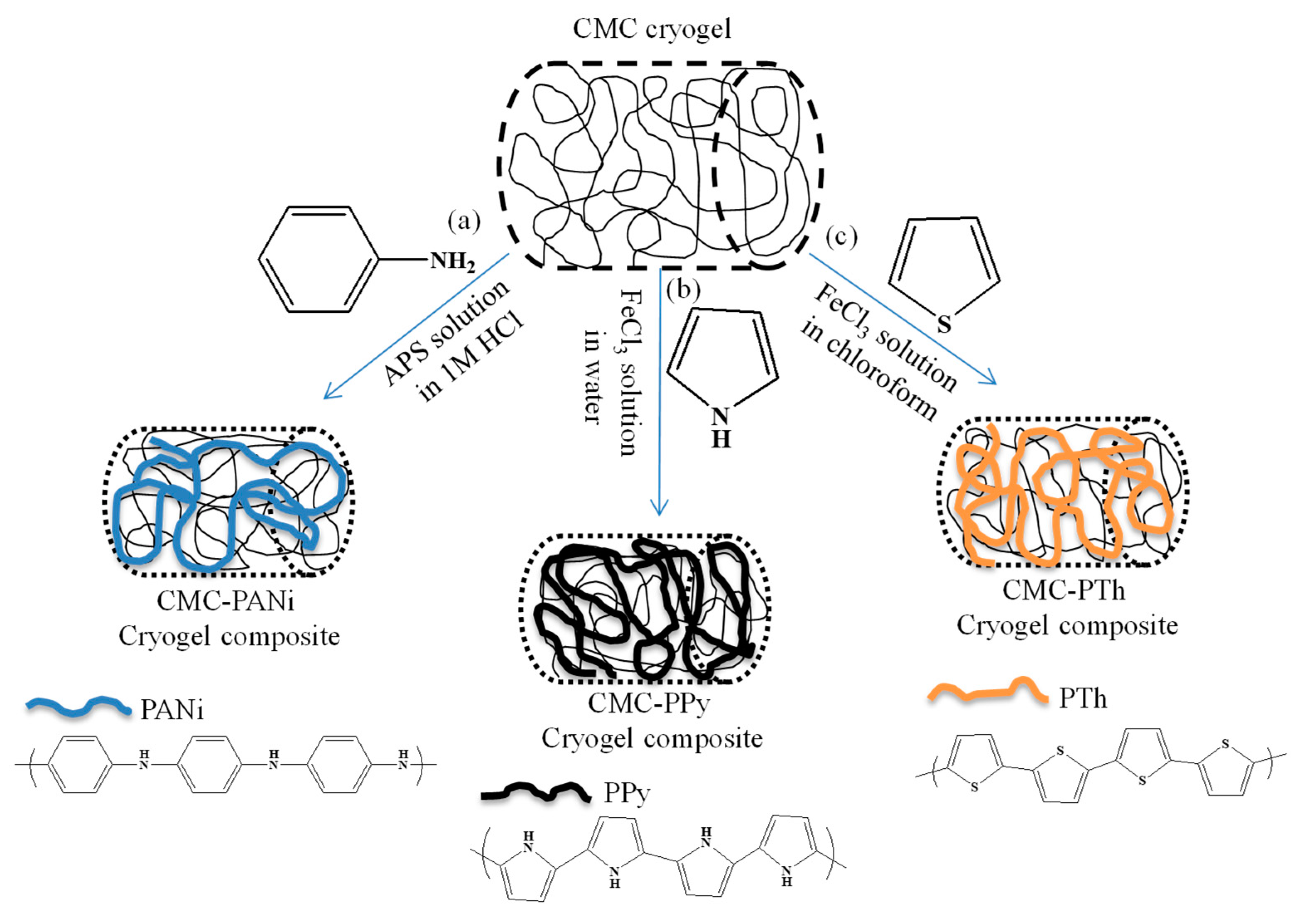
2.3. In Situ Synthesis of Conductive Polymers within CMC Cryogels

For in situ synthesis of poly(Aniline) (PANi) within CMC cryogels, a similar procedure reported in the literature was followed [41,42]. In short, 0.1 g CMC cryogels were placed in 10 mL ANi monomer for 2 h to load ANi monomer into CMC cryogels at a 100 rpm mxing rate at an ambient temperature. After that, the ANi monomer containing CMC cryogels were weighed, and the amount of loaded ANi was gravimetrically calculated. Then, ANi-loaded CMC cryogels were transferred in 200 mL 1 M HCl containing APS at 1:1.25 APS/ANi mole ratio according to the amount of ANi loaded into the CMC cryogel and stirred at 250 rpm for 30 min. Then, the prepared CMC–PANi cryogel conductive polymer composites were washed with DDW and ethanol, and dried in an oven at 50 °C.
In situ synthesis of poly(Pyrrole) (PPy) within CMC cryogels was also carried out in a similar procedure with some modification [41,42]. CMC cryogels weighing 0.1 g were placed in 10 mL Py monomer to load Py into CMC cryogels. Then, the Py-loaded CMC cryogels were placed into 0.05 M 250 mL FeCl3 solution in DDW and stirred at 250 rpm for 2 h at an ambient temperature for in situ polymerization of Py within CMC cryogels. Then, the prepared CMC-PPy cryogel conductive polymer composites were washed with DDW and ethanol, and dried in an oven at 50 °C.
The synthesis procedure of poly(Thiophene) (PTh) within CMC cryogels was also done based on a previously reported method [41,42]. Briefly, CMC cryogels weighing 0.1 g were placed in 10 mL of Th monomer to load Th into CMC cryogels. After that, Th loaded CMC cryogels were placed into 50 mL 0.03 M FeCl3 solution in chloroform and placed in an oil bath at 65 °C with reflux system, and stirred at 250 rpm for 16 h for the polymerization of Th within CMC cryogels. Finally, the prepared CMC–PTh cryogel conductive polymer composites were washed with DDW and ethanol, and dried in an oven at 50 °C.

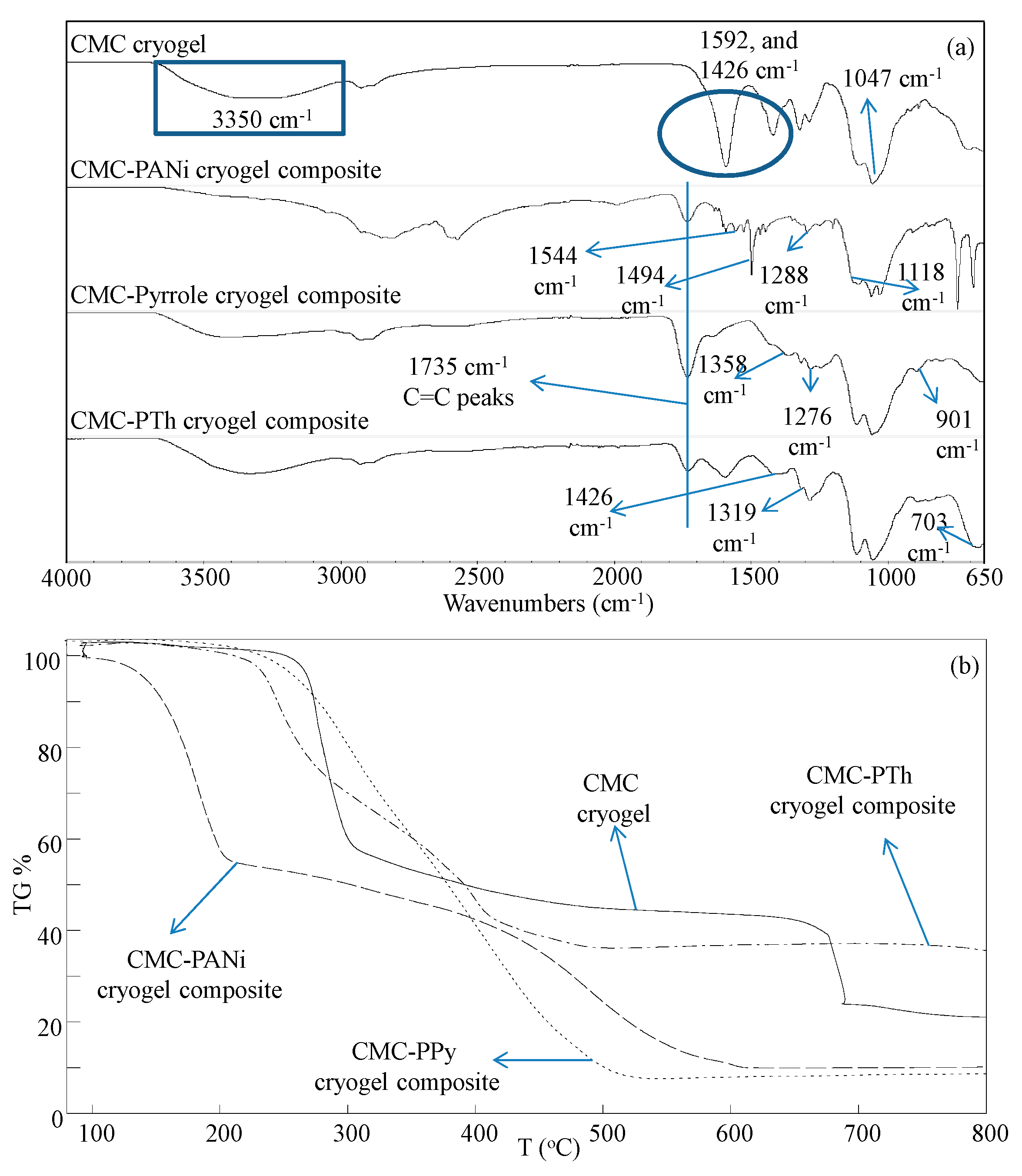
2.4. Characterization

The characterization of synthesized CMC cryogels and conductive polymer composites was done using Fourier transform infrared (FT-IR) spectrometer (Nicolet iS10, Thermo, Waltham, MA, USA), thermogravimetric analyzer (TGA, SII 6300, Exstar, Stoneham, MA, USA), and an electrometer (2400 Source-meter, Keithley, Cleveland, OH, USA) for conductivity measurements.

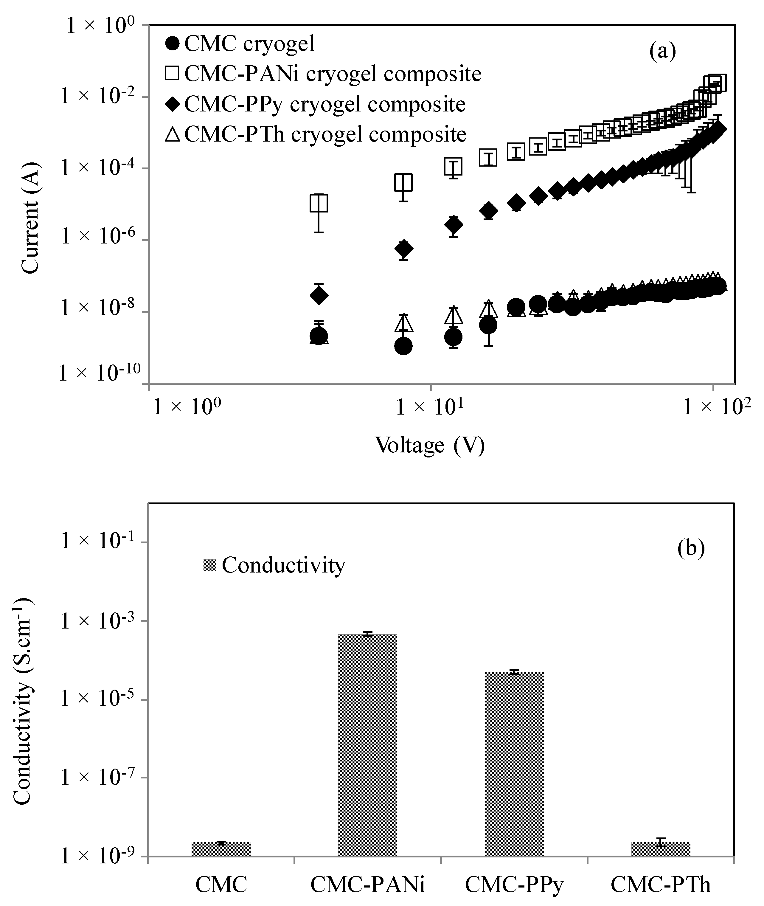
2.5. Conductivity Measurements

Conductivity of synthesized CMC cryogels and their corresponding PANi, PPy, and PTh composites was measured from the ohmic region of current–voltage (I–V) curves constructed from an electrometer using Equations (1) and (2):
V = I × R
σ = (1/R) × (l/A)
where ‘V’ is the voltage, ‘I’ is the current, ‘R’ is the bulk resistance, ‘σ’ is the conductivity, ‘1/R’ is the resistivity, ‘l’ is the thickness, and ‘A’ is the cross-sectional area of the sample.
In the conductivity measurements, small pieces of conductive carbon tapes (3 mm × 4 mm) were attached at the top and bottom sides of CMC cryogels and/or CMC–conductive polymer composites, and then the electrodes of the electrometer were contacted with these carbon tapes. Next, the I–V curves were obtained by applying voltages up to 100 V to determine the conductivity of the samples.

3. Results and Discussion

3.1. Synthesis and Characterization of In Situ Synthesized Conductive Polymer CMC Cryogel Composites

The well-known cryo-crosslinking technique was used in the preparation of CMC cryogels having an interconnected super macroporous structure. Scanning Electron Microscopy (SEM) images of CMC cryogels synthesized using 100% DVS crosslinker based on the repeating unit of CMC were previously reported by our group reporting the super macroporous structure of CMC cryogels with a pore size in a range of 1–100 µm [40]. Recently, the synthesis of conductive polymers within cryogels was reported [41,42]. The schematic presentation of in situ synthesis of conductive polymers within CMC cryogels is given in Figure 1a–c for PANi, PPy, and PTh synthesis, respectively. Briefly, 0.1 g of purified cylindrical CMC cryogel pieces was placed into ANi, Py, and Th monomers separately about 2 h for loading of monomers into CMC cryogels. Then, depending on monomer, the conductive monomer-loaded CMC cryogels were placed into the appropriate initiator solution, as described above.
As a result of in situ synthesis of conductive polymer, the interconnected super macro pores of CMC cryogels were filled with PANi or PPy, or PTh, as shown in Figure 1. The amounts of loaded ANi, Py, and Th into CMC cryogels; the amounts of in situ synthesized conductive polymers within CMC cryogels; and in situ polymerization efficiency of conductive polymers within CMC cryogels are summarized in Table 1. The ANi, Py, and Th loaded CMC cryogels were weighed and the amount of incorporation of each ANi, Py, and Th monomer into CMC structure is calculated. Briefly, cryogels of known weight were placed in monomers and weighed again to calculate the loaded amount of the corresponding monomers.
In brief, the weight of known cryogel was placed into monomers of the desired conductive polymer and weighted again to calculate the loaded amount of the corresponding monomers. The amounts of in situ prepared conductive polymers were then calculated from the weight of the cryogel–conductive polymer composites. The percent yield of in situ polymerized conductive polymers was calculated from the amount of in situ polymerized conductive polymers and loaded amount of monomer.
Upon polymerization of ANi, Py, and Th within CMC cryogels by placing into corresponding solutions for the in situ synthesis of conductive PANi, PPy, and PTh polymers within CMC cryogels, the weights of conductive PANi, PPy, and PTh polymers were computed as 0.97 ± 0.11, 0.23 ± 0.01, and 0.11 ± 0.01 g, respectively. The in situ polymerization efficiency of conductive PANi, PPy, and PTh within CMC cryogels was gravimetrically assessed as 46.21% ± 5.44%, 10.95% ± 0.21%, and 5.18% ± 0.49%, respectively.
The FT-IR spectra and TGA thermograms of CMC cryogel, as well as CMC–PANi, CMC–PPy, and CMC–PTh composites, are shown in Figure 2a,b, respectively. In Figure 2a, the FT-IR spectrum of CMC cryogels gave characteristic peaks as wide band around 3350 cm−1 assigned to –OH stretching, asymmetric stretching of –COO- at 1592 cm−1, symmetric stretching of -COO- at 1423 cm−1, and –CO stretching at 1047 cm−1, respectively. On the other hand, new bands appeared at 1544 cm−1 corresponding to benzenoic-quinonic nitrogen, at 1494 cm−1 for aromatic C-C, at 1288 cm−1 for aromatic amine group, and at 1118 cm−1 for C-N-C stretching in the FT-IR spectrum of CMC–PANi cryogel composites, which are in accordance with the literature [43]. The characteristic bands of PPy were also observed in the FT-IR spectrum of CMC–PPy cryogel composites at 1358 cm−1 corresponding to =C-H in-plane vibrations, at 1276 cm−1 for N-C stretching vibrations, and at 901 cm−1 assigned to the presence of polymerized pyrrole units [44]. Moreover, the peaks observed at 703, 1319, and 1426 cm−1 from the FT-IR spectrum of CMC–PTh cryogel composites were assigned to α–α connection between thiophene molecules [45], and C-H in-plane bending vibrations of Th molecules, respectively [46].
The thermal stability and degradation steps of CMC cryogel, CMC–PANi, CMC–PPy, and CMC–PTh cryogel composites were compared with TGA analysis and corresponding TGA thermograms are given in Figure 2b. The first degradation step of CMC cryogel was observed between 260 and 308 °C with 41.5% weight loss from the thermogram, the second step of degradation was observed between 676 and 694 °C with 75.8% weight loss, and 78.8% weight loss was observed at 800 °C. On the other hand, it was deduced that the thermal stability of CMC cryogels decreased with the in situ synthesis of PANi conductive polymer, where the first degradation step was seen between 137 and 208 °C with 43.1% weight loss, the second step of degradation was observed between 425 and 607 °C with 89.8% weight loss, and 91.2% weight loss was attained at 800 °C from the TGA thermogram of the CMC–PANi cryogel composite. The one step degradation of CMC–PPy cryogel composites was noticed between 224 and 517 °C with 91.2% weight loss, and 92.1% weight loss was observed at 800 °C. Finally, the TGA thermogram of CMC–PTh cryogel composites also resulted in two degradation steps, starting between 222 and 278 °C with 16.5% weight loss, between 373 and 414 °C with 58.5% weight loss, and 63.8% weight loss was observed at 800 °C. TGA thermograms of CMC cryogel, CMC–PANi, CMC–PPy, and CMC–PTh cryogel composites clearly show that the thermal stability of CMC cryogel decreased by in situ synthesis of PANi, and slightly decreased for the in situ synthesis of PPy and PTh conductive polymers.

3.2. Conductivity Measurements

Although the reason behind the conductivity for conjugated organic molecules was initially assumed to be derived from unfilled electronic valence and conduction bands, it was later shown that the conductivity can be associated with spineless charge carriers such as soliton, polaron, and bipolaron, after the discovery of conductive polymers such as PANi, PPy, and PTh [47]. In this study, the conductivity of CMC cryogels, as well as the changes in conductivities of CMC–PANi, CMC–PPy, and CMC–PTh cryogel composites, were determined by using an electrometer from the ohmic region of obtained I–V curves. In Figure 3a, the digital camera images of CMC cryogel, CMC–PANi, CMC–PPy, and CMC–PTh cryogel composites are given. It was clearly seen that the white color of CMC cryogels turned to black after in situ synthesis of PANi and PPy, and also turned to light brown upon in situ synthesis of PTh conductive polymer.
The schematic representation of electrometer measurement setup is shown in Figure 3b. As can be seen, the probes of electrometer were contacted to carbon tapes that were attached at the top and bottom sides of CMC-based cryogels and cryogel composites. The corresponding I–V curves of CMC cryogel, CMC–PANi, CMC–PPy, and CMC–PTh are given in Figure 4a.
The conductivity values were calculated from I–V curves using Equations (1) and (2), and are illustrated in Figure 4b for CMC cryogel, CMC–PANi, CMC–PPy, and CMC–PTh cryogel composites. The conductivity of CMC cryogels was calculated as 2.21 × 10⁻⁹ ± 1.98 × 10⁻¹⁰ S·cm−1. An approximately 200 K-fold increase was observed in the conductivity of CMC cryogels by the in situ synthesis of PANi, which was calculated as 4.58 × 10⁻⁴ ± 5.68 × 10⁻⁵ S·cm−1. The conductivity of CMC–PPy cryogel composites was calculated as 5.02 × 10⁻⁵ ± 5.54 × 10⁻⁶ S·cm−1 with approximately a 25 K-fold increase as compared with the conductivity of bare CMC cryogel. On the other hand, the difference between conductivity of CMC cryogels and CMC–PTh cryogel composites was insignificant, where the calculated conductivity value of CMC–PTh cryogel composites was 2.28 × 10⁻⁹ ± 5.24 × 10⁻¹⁰ S·cm−1. Among the monomers used for in situ syntheses of conductive polymers within CMC cryogel, Th polymerization stands out as the most difficult one. The results summarized in Table 1 confirm this phenomenon as the in situ polymerization efficiency for PTh within CMC cryogels was calculated as 5%. Therefore, the observation of some major differences in conductivity values among the conductive polymers and CMC and CMC–PTh cryogel composites can be explained by a very small amount of PTh conductive polymer in CMC cryogels.
The highest increase in conductivity was observed after in situ synthesis of PANi with a 200 K-fold increase, following Py with a 25 K-fold increase, which could be owing to their higher amounts within CMC pores, allowing better conductivity.

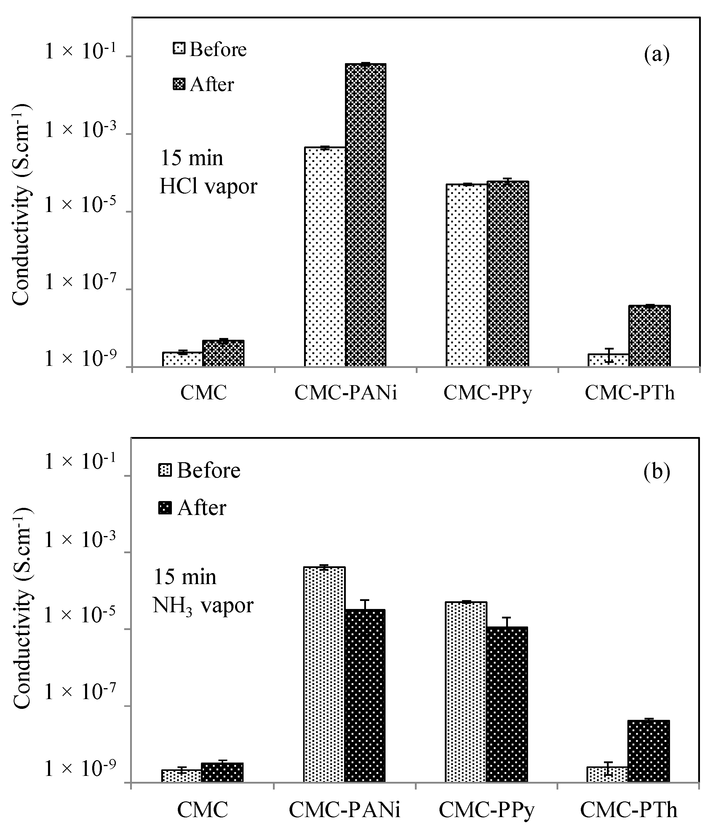
3.3. The Change in Conductivity Upon Exposure to HCl and NH3 Vapors

The potential sensor use of the prepared CMC cryogel, CMC–PANi, CMC–PPy, and CMC–PTh cryogel composites for HCl and NH3 vapors was tested by measuring the changes in conductivities of prepared CMC-based cryogels by following literature [41]. In brief, CMC cryogel, CMC–PANi, CMC–PPy, and CMC–PTh cryogel composites were treated with HCl and NH3 vapors for 15 min by employing a simple experimental set up [41]. Cryogel composites were exposed to HCl and NH3 vapors using a simple set up. In brief, two funnels were connected with a glass fritted neck, where cryogel composites were placed on the top surface of the glass frit connected with another funnel containing a glass cotton that is attached to HCl or NH3 solutions with a valve for the release of vapors. The conductivities of CMC cryogel, CMC–PANi, CMC–PPy, and CMC–PTh cryogel composites were calculated before and after gas exposures. The conductivity changes in CMC cryogel, CMC–PANi, CMC–PPy, and CMC–PTh cryogel composites after treating with HCl vapor for 15 min are demonstrated in Figure 5a, and the values are summarized in Table 2. The conductivity of CMC cryogel was increased from 2.31 × 10⁻⁹ ± 2.19 × 10⁻¹⁰ S·cm−1 to 4.59 × 10⁻⁹ ± 6.33 × 10⁻¹⁰ S·cm−1 with approximately a twofold increase after 15 min of HCl vapor treatment. Moreover, the conductivity of CMC–PANi cryogel composite increased from 4.36 × 10⁻⁴ ± 4.63 × 10⁻⁵ S·cm−1 to 6.24 × 10⁻² ± 5.21 × 10⁻³ S·cm−1 with approximately a 150-fold increase after 15 min of HCl vapor treatment. Further, the conductivity of CMC–PTh was increased from 2.12 × 10⁻⁹ ± 8.36 × 10⁻⁹ S·cm−1 to 3.67 × 10⁻⁸ ± 3.36 × 10⁻⁹ S·cm−1 with approximately a 20-fold increase after 15 min of HCl vapor treatment. The change in conductivity of CMC–PPy was found to be insignificant as the conductivity was increased to 5.97 × 10⁻⁵ ± 9.32 × 10⁻⁶ S.cm-1 from 4.98 × 10⁻⁵ ± 3.57 × 10⁻⁶ S·cm−1. Overall, the highest conductivity change was observed for CMC–PANi cryogels with a 150-fold increases after HCl vapor treating for 15 min. As HCl was also used for the in situ synthesis of PANi within CMC cryogels, this conductivity increase in the CMC–PANi cryogel composite can be explained by the further doping effect of HCl vapor for PANi conductive polymers within the CMC superporous network.
The conductivity changes in CMC cryogel, CMC–PANi, CMC–PPy, and CMC–PTh cryogel composites after treating with NH3 vapor for 15 min are shown in Figure 5b. As shown in Table 2, the conductivity changes in CMC cryogel, CMC–PANi, CMC–PPy, and CMC–PTh cryogel composites are from 2.16 × 10⁻⁹ ± 3.71 × 10⁻¹⁰ S·cm−1 to 3.11 × 10⁻⁹ ± 5.95 × 10⁻¹⁰ S·cm−1, from 4.11 × 10⁻⁴ ± 5.32 × 10⁻⁵ S·cm−1 to 3.27 × 10⁻⁵ ± 2.56 × 10⁻⁵ S·cm−1, from 5.16 × 10⁻⁵ ± 4.38 × 10⁻⁶ S·cm−1 to 1.11 × 10⁻⁵ ± 8.73 × 10⁻⁶ S·cm−1, and from 2.51 × 10⁻⁹ ± 9.17 × 10⁻¹⁰ S·cm−1 to 4.14 × 10⁻⁸ ± 4.28 × 10⁻⁹ S·cm−1, respectively. The highest conductivity change was observed for the CMC–PTh cryogel composite with a 15-fold increase upon 15 min NH3 vapor treatment. Besides, 12-fold and 5-fold decreases were observed in the conductivity of CMC–PANi and CMC–PPy cryogel composites, respectively.
As a consequence, it can be assumed that the amounts of conductive polymer in CMC cryogel templates and the types of conductive polymer can affect the potential sensor applications of composite systems against different gases, for example, HCl and NH3 vapor.

4. Conclusions

Herein, CMC cryogels from natural sources were utilized as a template for in situ PANi, PPy, and PTh conductive polymer synthesis for the first time in the literature. It was observed that the conductivity of CMC cryogels was increased by in situ preparation of PANi and PPy conductive polymers to 4.36 × 10⁻⁴ ± 4.63 × 10⁻⁵ S·cm−1 with a 200 K-fold increase, and 4.98 × 10⁻⁵ ± 3.57 × 10⁻⁶ S·cm−1 with approximately a 25 K-fold increase according to conductivity of CMC cryogels, respectively. The potential sensor application of CMC-based PANi, PPy, and PTh cryogel composites was also tested against HCl and NH3 vapor exposure. The most significant conductivity difference was realized for CMC–PANi cryogel against HCl vapor by 15 min exposure time, with a 150-fold increase in the conductivity attributed to the doping of PANi conductive polymers with HCl vapor. Additionally, a 15-fold increase was observed in the conductivity of CMC–PTh, and a 12-fold decrease was observed in the conductivity of CMC–PANi against NH3 vapor exposure by 15 min exposure. Overall, it can be concluded that CMC–PANi, CMC–PPY, and CMC–PTh cryogel composites can be used as a sensor for HCl and NH3 vapors. Importantly, the innate biocompatibility of CMC cryogels, and sustainability of CMC with the capability of in situ prepared PANi, PPY, and PTh conductive polymers, make these natural–synthetic polymer composites promising materials for biotechnological and biomedical applications.

Author Contributions

Conceptualization, N.S.; Formal analysis, S.D. and S.D.S.; Funding acquisition, N.S.; Investigation, N.S. and S.D.; Methodology, N.S., S.D., and S.D.S.; Resources, N.S.; Supervision, N.S.; Writing—original draft, S.D. and S.D.S.; Writing—review & editing, N.S. All authors have read and agreed to the published version of the manuscript.

Funding

This research received no external funding.

Conflicts of Interest

The authors declare no conflict of interest.

References

  1. Shirakawa, H. The discovery of polyacetylene film: The dawning ofan era of conducting polymers (Nobel lecture). Angew. Chem. Int. Ed. 2001, 40, 2575–2580. [Google Scholar] [CrossRef]
  2. Heeger, A. Semiconducting and metallic polymers: The fourth gen-eration of polymeric materials. Synt. Metal. 2002, 125, 23–42. [Google Scholar] [CrossRef]
  3. Guo, B.; Glavas, L.; Albertsson, A.C. Biodegradable and electrically conducting polymers for biomedical application. Prog. Polym. Sci. 2013, 38, 1263–1286. [Google Scholar] [CrossRef]
  4. Cho, J.; Shin, K.H.; Jang, J. Micropatterning of conducting polymer tracks on plasma treated flexible substrate using vapor phase polymerization-mediated inkjet printing. Synth. Met. 2010, 160, 1119–1125. [Google Scholar] [CrossRef]
  5. Gonzalez-Macia, L.; Morrin, A.; Smyth, M.R.; Killard, A.J. Advanced printing and deposition methodologies for the fabrication of biosensors and biodevices. Analyst 2010, 135, 845–867. [Google Scholar] [CrossRef] [PubMed] [Green Version]
  6. Ummartyotin, S.; Wu, C.; Sain, M.; Manuspiya, H. Deposition of PEDOT: PSS nanoparticles as a conductive microlayer anode in OLED devices by desktop inkjet printer. J. Nanomater. 2011, 2011, 606714. [Google Scholar] [CrossRef]
  7. Alshammary, B.; Walsh, F.C.; Herrasti, P.; Ponce de Leon, C. Electrodeposited conductive polymers for controlled drug release:polypyrrole. J. Solid State Electrochem. 2016, 20, 839–859. [Google Scholar] [CrossRef] [Green Version]
  8. Stenger-Smith, J.D. Intrinsically electrically conducting polymers, synthesis, characterization, and their applications. Prog. Polym. Sci. 1998, 23, 57–79. [Google Scholar] [CrossRef]
  9. Gurunathan, K.; Murugan, A.V.; Marimuthu, R.; Mulik, U.P.; Amalnerkar, D.P. Electrochemically synthesized conducting polymeric materials for applications towards technology in electronics, optoelectronics and energy storage devices. Mater. Chem. Phys. 1999, 61, 173–191. [Google Scholar] [CrossRef]
  10. Long, Y.Z.; Li, M.M.; Gu, C.Z.; Wan, M.X.; Duvail, J.L.; Liu, Z.W.; Fan, Z.Y. Recent advances in synthesis, physical properties and applications of con-ducting polymer nanotubes and nanofibers. Prog. Polym. Sci. 2011, 36, 1415–1442. [Google Scholar] [CrossRef]
  11. Wang, X.D.; Gu, X.S.; Yuan, C.W.; Chen, S.J.; Zhang, P.Y.; Zhang, T.Y.; Yao, J.; Chen, F.; Chen, G. Evaluation of biocompatibility of polypyrrole in vitro and in vivo. J. Biomed. Mater. Res. A 2004, 68, 411–422. [Google Scholar] [CrossRef] [PubMed]
  12. Ramanaviciene, A.; Kausaite, A.; Tautkus, S.; Ramanavicius, A. Biocompatibility of polypyrrole particles: An in-vivo study in mice. J. Phar. Pharmacol. 2007, 59, 311–315. [Google Scholar] [CrossRef] [PubMed]
  13. Kumar, A.; Banerjee, S.; Sailia, J.P.; Konwar, B.K. Swift heavy ion irradiation induced enhancement in the antioxidant activity and biocompatibility of polyaniline nanofiber. Nanaotechnology 2010, 21, 175102. [Google Scholar] [CrossRef] [PubMed]
  14. Wang, C.H.; Dong, Y.Q.; Sengothi, K.; Tan, K.L.; Kang, E.T. In-vivo tissue response to polyaniline. Synt. Metal. 1999, 102, 1313–1314. [Google Scholar] [CrossRef]
  15. Zhao, H.C.; Zhu, B.; Sekine, J.; Luo, S.C.; Yu, H.H. Oligoethylene-glycol-functionalized polyoxythiophenes for cell engineering: Syntheses characterizations, and cell compatibilities. ACS Appl. Mater. Interfaces 2012, 4, 680–686. [Google Scholar] [CrossRef] [PubMed]
  16. Garner, B.; Georgevich, A.; Hodgson, A.J.; Liu, L.; Wallace, G.G. Polypyrrole-heparin composites as stimulus-responsive substrates for endothelial cell growth. J. Biomed. Mater. Res. 1999, 44, 121–129. [Google Scholar] [CrossRef]
  17. Kim, D.H.; Wiler, J.A.; Anderson, D.J.; Kipke, D.R.; Martin, D.C. Conducting polymers on hydrogel-coated neural electrode provide sensitive neural recordings in auditory cortex. Acta Biomater. 2010, 6, 57–62. [Google Scholar] [CrossRef]
  18. Persson, K.M.; Karlsson, R.; Svennersten, K.; Loffler, S.; Jager, E.W.H.; Richter-Dahlfors, A.; Konradsson, P.; Berggren, M. Electronic control of cell detachment using a self-doped conducting polymer. Adv. Mater. 2011, 23, 4403–4408. [Google Scholar] [CrossRef] [Green Version]
  19. Lee, J.W.; Serna, F.; Nickels, J.; Schmidt, C.E. Carboxylic acid-functionalized conductive polypyrrole as a bioactive platform for cell adhesion. Biomacromology 2006, 7, 1692–1965. [Google Scholar] [CrossRef] [Green Version]
  20. Nambiar, S.; Yeow, J.T.W. Conductive polymer-based sensors for biomedical applications. Biosens. Bioelectron. 2011, 26, 1825–1832. [Google Scholar] [CrossRef]
  21. Wang, Q.; Wang, Q.; Teng, W. Injectable, degradable, electroactive nanocomposite hydrogels containing conductive polymer nanoparticles for biomedical applications. Int. J. Nanomed. 2016, 11, 131–145. [Google Scholar] [CrossRef] [PubMed] [Green Version]
  22. Shah, A.M.; KAdir, M.R.A.; Razak, S.I.A. Novel PLA-based conductive polymercomposites for biomedical applications. JOM 2017, 69, 2838–2843. [Google Scholar] [CrossRef]
  23. Balint, R.; Cassidy, N.J.; Cartmell, S.H. Conductive polymers: Towards a smart biomaterial for tissue engineering. Acta Biomater. 2014, 10, 2341–2353. [Google Scholar] [CrossRef] [PubMed]
  24. Akbarnejad, Z.; Eskandary, H.; Vergallo, C.; Nematollahi-Mahani, S.N.; Dini, L.; Darvishzadeh, F. Effects of extremely low-frequency pulsed electromagnetic fields (ELF-PEMFs) on glioblastoma cells (U87). Electreomag. Biol. Med. 2017, 36, 238–247. [Google Scholar] [CrossRef]
  25. Scanziani, M.; Häusser, M. Electrophysiology in the age of light. Nature 2009, 461, 930. [Google Scholar] [CrossRef]
  26. Clayton, R.H.; Bernus, O.; Cherry, E.M.; Dierckx, H.; Fenton, F.H.; Mirabella, L.; Panfilov, A.V.; Sachse, F.B.; Seemann, G.; Zhang, H. Models of cardiac tissue electrophysiology: Progress, challenges and open questions. Prog. Biophys. Mol. Biol. 2011, 104, 22–48. [Google Scholar] [CrossRef]
  27. Vasquez-Sancho, F.; Abdollahi, A.; Damjanovic, D.; Catalan, G. Flexoelectricity in Bones. Adv. Mater. 2018, 30, 1705316. [Google Scholar] [CrossRef]
  28. Cantu, T.; Walsh, K.; Pattani, V.P.; Moy, A.J.; Tunnel, J.W.; Irvin, J.A.; Betancourt, T. Conductive polymer-based nanoparticles for lase-mediated photothermal ablation of cancer: Synthesis, characterization, and in vitro evaluation. Int. J. Nanomed. 2017, 12, 615–632. [Google Scholar] [CrossRef] [Green Version]
  29. Hardy, J.G.; Lee, J.Y.; Schmidt, C.E. Biomimetic conducting polymer-based tissue scaffolds. Cur. Opin. Biotechnol. 2013, 24, 847–854. [Google Scholar] [CrossRef] [Green Version]
  30. Lassalle, N.; Vieil, E.; Correia, J.P.; Abrantes, L.M. Study of DNA hybridization on polypyrrole grafted with oligonucleotides by photocurrent spectroscopy. Biosens. Bioelectron. 2001, 16, 295–303. [Google Scholar] [CrossRef]
  31. Rozlosnik, N. New directions in medical biosensors employing poly(3,4-ethylenedioxy thiophene) derivative-based electrodes. Anal. Bioanal. Chem. 2009, 395, 637–645. [Google Scholar] [CrossRef] [PubMed]
  32. Kleber, C.; Bruns, M.; Lienkamp, K.; Rühe, J.; Asplund, M. An interpenetrating, microstructurable and covalently attached conducting polymer hydrogel for neural interfaces. Acta Biomater. 2017, 58, 365–375. [Google Scholar] [CrossRef] [PubMed]
  33. Shklovsky, J.; Reuveny, A.; Sverdlov, Y.; Krylov, S.; Shacham-Diamand, Y. Towards fully polymeric electroactive micro actuators with condutive polymer electrodes. Microelectron. Eng. 2018, 199, 58–62. [Google Scholar] [CrossRef]
  34. Zhou, J.; Mulle, M.; Zhang, Y.; Xu, X.; Li, E.Q.; Han, F.; Thoroddsen, S.T.; Lubineau, G. High-ampacity conductive polymer microfibers as fast response wearable heaters and electromechanical actuators. J. Mater. Chem. C. 2016, 4, 1238–1249. [Google Scholar] [CrossRef] [Green Version]
  35. Chapman, C.A.R.; Cuttaz, E.A.; Goding, J.A.; Green, R.A. Actively controlled local drug delivery using conductive polymer-based devices. Appl. Phys. Lett. 2020, 116, 010501. [Google Scholar] [CrossRef] [Green Version]
  36. Li, Y.; Neoh, K.G.; Kang, E.T. Controlled release of heparin from polypyrrole-poly(vinyl Alcohol) assembly by electrical stimulation. J. Biomed. Mater. Res. Part A 2005, 73, 171–181. [Google Scholar] [CrossRef]
  37. Schmidt, C.E.; Shastri, V.R.; Vacanti, J.P.; Langer, R. Stimulation of neurite outgrowth using an electrically conducting polymer. Proc. Natl. Acad. Sci. USA 1997, 94, 8948–8953. [Google Scholar] [CrossRef] [Green Version]
  38. Nezakati, T.; Tan, A.; Lim, J.; Cormia, R.D.; Teoh, S.H.; Seifalian, A.M. Ultra-low percolation threshold POSS-PCL/graphene electrically conductive polymer: Neural tissue engineering nanocomposites for neurosurgery. Mater. Sci. Eng. C 2019, 104, 109915. [Google Scholar] [CrossRef]
  39. Nezakati, T.; Seifalian, A.; Tan, A.; Seifalian, A.M. Conductive polymers: Opportunities and challenges in biomedical applications. Chem. Rev. 2018, 118, 6766–6843. [Google Scholar] [CrossRef]
  40. Sengel, S.B.; Sahiner, M.; Aktas, N.; Sahiner, N. Halloysite-carboxymethyl cellulose cryogel composite from natural sources. Appl. Cay. Sci. 2017, 140, 66–74. [Google Scholar] [CrossRef]
  41. Sahiner, N.; Demirci, S.; Aktas, N. Superporous cryogel/conductive composite systems for potential sensor applications. J. Polym. Res. 2017, 24, 126. [Google Scholar] [CrossRef]
  42. Sahiner, N.; Demirci, S. Conducting semi-interpenetrating polymeric composites via the preparation of poly(aniline), poly(thiophene), and poly(pyrrole) polymers within superporous poly(acrylic acid) cryogels. React. Funct. Polym. 2016, 105, 60–65. [Google Scholar] [CrossRef]
  43. Veara, R.A.; Romero, B.H.; Ahumada, E. Synthesis and characterization of polyaniline and poly-ortho-methoxyaniline behavior against carbon steel corrosion. J. Chill. Chem. Soc. 2003, 48, 1. [Google Scholar]
  44. Xu, C.; Sun, J.; Gao, L. Synthesis of novel hierarchical graphene/polypyrrole nano sheet composite and their superior electrochemical performance. J. Mater. Chem. 2011, 21, 11253–11258. [Google Scholar] [CrossRef]
  45. Olowu, R.A.; Arotiba, O.; Mailu, S.N.; Warto, T.T.; Baker, P.; Iwuoha, E. Electrochemical aptasensor for endocrine disrupting 17β-estradiol based on a poly(3,4-ethylenedioxylthiopene)-gold nanocomposite platform. Sensors 2010, 10, 9872–9890. [Google Scholar] [CrossRef] [PubMed] [Green Version]
  46. Liao, J.; Wang, L.; Bao, W. A process for desulfurization of coking benzene by a two-step method with reuse of sorbent/thiophene and its key procedures. Green Chem. 2015, 17, 3164–3175. [Google Scholar] [CrossRef]
  47. Park, H.S.; Ko, S.J.; Park, J.S.; Kim, J.Y.; Song, H.K. Redox-active charge carriers of conducting polymers as a tuner of conductivity and its potential window. Sci. Rep. 2013, 3, 2454. [Google Scholar] [CrossRef] [Green Version]
Figure 1. The schemcatic presentation of in situ synthesis of (a) poly(Aniline) (PANi), (b) poly(Pyrrole) (PPy), and (c) poly(Thiophene) (PTh) conductive polymers within carboxymethyl cellulose (CMC) cryogels. APS, ammonium persulfate.
Jcs 04 00033 g001
Figure 2. (a) Fourier transform infrared (FT-IR) spectrum and (b) thermogravimetric analysis (TGA) thermograms of CMC cryogel, CMC–PANi, CMC–PPy, and CMC–PTh cryogel composites.
Jcs 04 00033 g002
Figure 3. (a) Digital camera images of synthesized CMC cryogel, CMC–PANi, CMC–PPy, and CMC–PTh cryogel composites; and (b) schematic representation of electrometer measurement.
Jcs 04 00033 g003
Figure 4. The comparison of (a) current–voltage (I–V) curves obtained from electrometer; and (b) calculated conductivity values of CMC cryogel, CMC–PANi, CMC–PPy, and CMC–PTh cryogel composites.
Jcs 04 00033 g004
Figure 5. The change in the conductivities of CMC cryogel, CMC–PANi, CMC–PPy, and CMC–PTh cryogel composites after 15 min (a) HCl and (b) NH3 vapor exposure.
Jcs 04 00033 g005
Table 1. The amount of loaded Aniline (ANi), Pyrrole (Py), and Thiophene (Th); the amount of in situ synthesized cryogel composites; and in situ polymerization yield. CMC, carboxymethyl cellulose.
Materials (Cryogel Composite)Weigth of CMC Cryogels (g)Loaded Amount of Monomer (g)Amount of Composite Cryogel (g)Yield of In Situ Polymerization (%)
CMC–PANi0.1 ± 0.011.98 ± 0.020.97 ± 0.1146.2 ± 5.44
CMC–PPy0.1 ± 0.011.94 ± 0.030.23 ± 0.0110.9 ± 0.21
CMC–PTh0.1 ± 0.011.92 ± 0.030.11 ± 0.015.18 ± 0.49
Table 2. The changes in the conductivities of CMC cryogel, CMC–PAN, CMC–PPY, and CMC–PTh cryogel composites after 15 min HCl and NH3 vapor treatment.
MaterialsConductivity (S·cm-1)
HCl VaporChange (fold)NH3 VaporChange (fold)
BeforeAfterBeforeAfter
CMC2.31 × 10−94.59 × 10−922.16 × 10−93.11 × 10−91.5
CMC–PANi4.36 × 10−46.24 × 10−21434.11 × 10−43.27 × 10−512
CMC–PPy4.98 × 10−55.97 × 10−51.25.16 × 10−51.11 × 10−55
CMC–PTh2.12 × 10−93.67 × 10−8172.51 × 10−94.14 × 10−816

