Hybrid Effect in In-Plane Loading of Carbon/Glass Fibre Based Inter- and Intraply Hybrid Composites

 , ,
, ,
Abstract
1. Introduction
2. Experimental Details
2.1. Materials
2.2. Manufacturing Methods
2.2.1. Fabric Manufacturing
2.2.2. Composite Fabrication
2.3. Material Characterisation
2.3.1. Physical Properties, Density and Fibre Volume Fraction
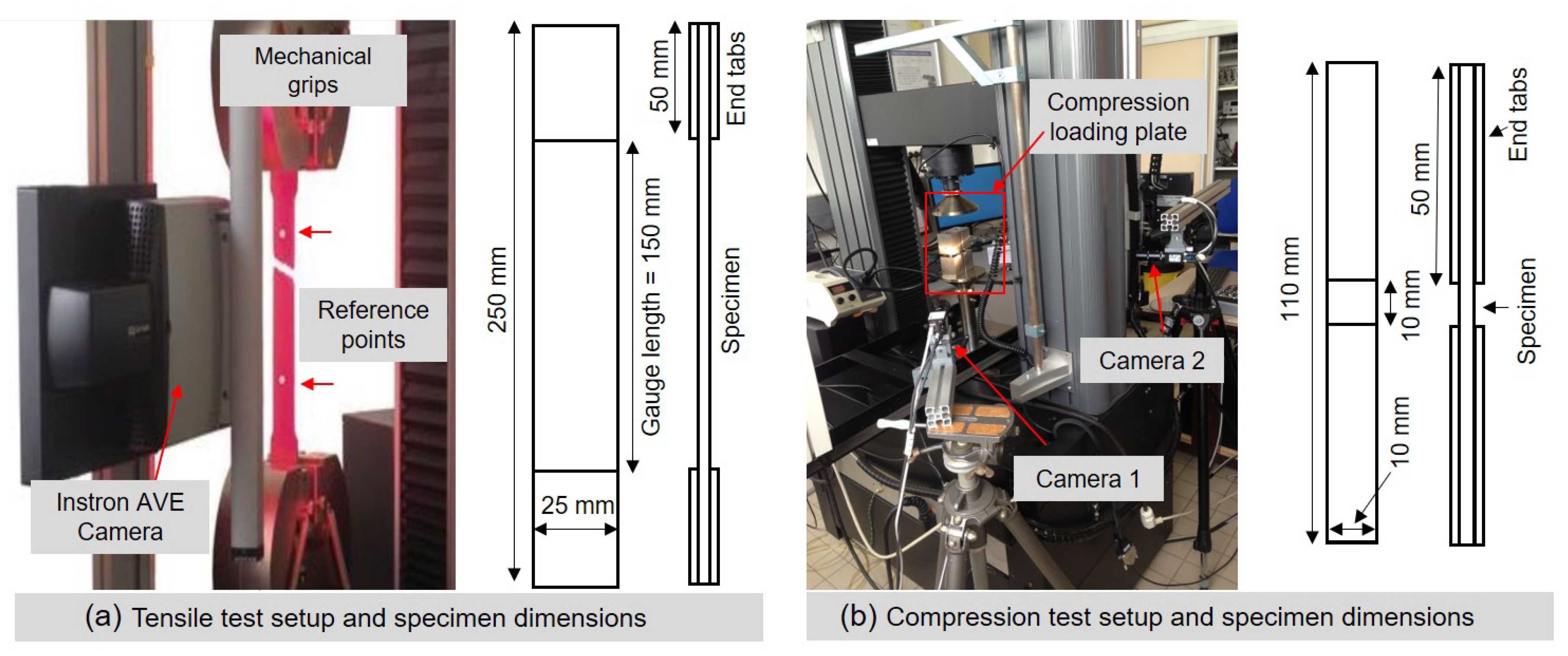
2.3.2. Tensile Properties
2.3.3. Compression Properties
2.3.4. Fractography
3. Results and Discussion
3.1. Density and Fibre Volume Fraction
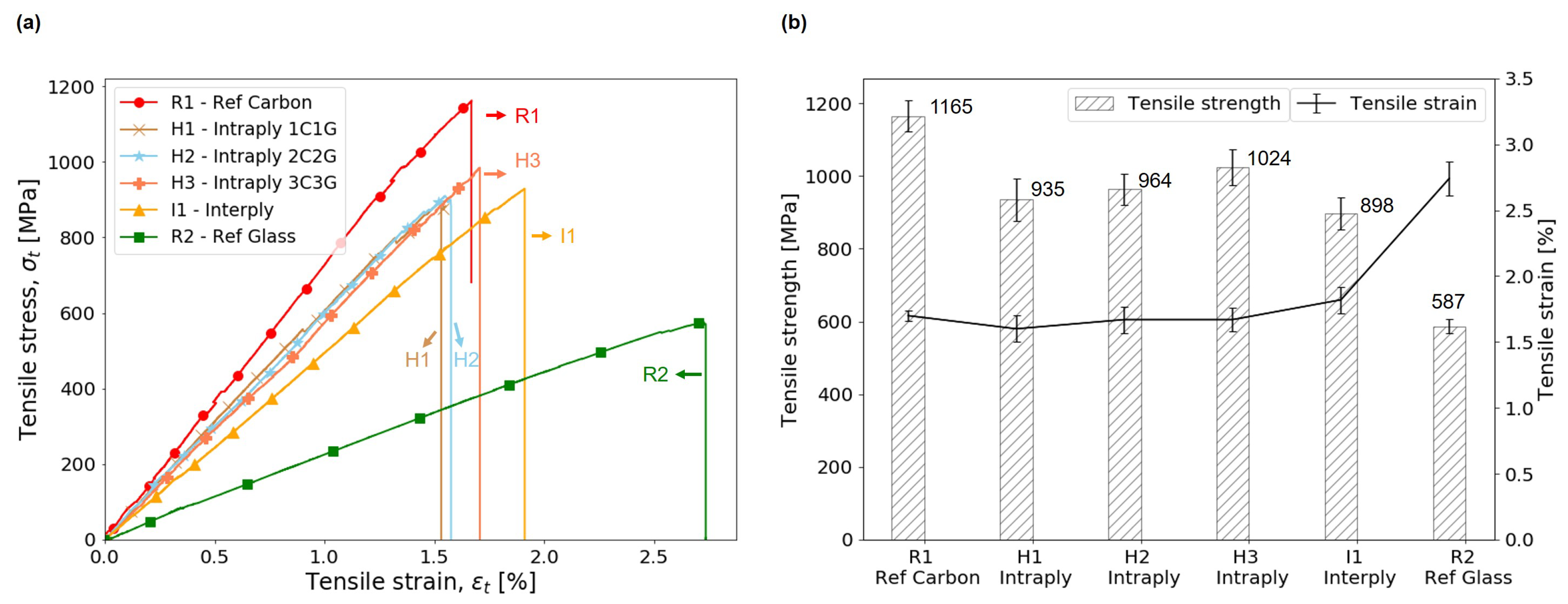
3.2. Tensile Properties
3.2.1. Stiffness
3.2.2. Failure Characteristics
3.3. Compression Properties
3.3.1. Stiffness
3.3.2. Failure Characteristics
3.4. Damage Morphology
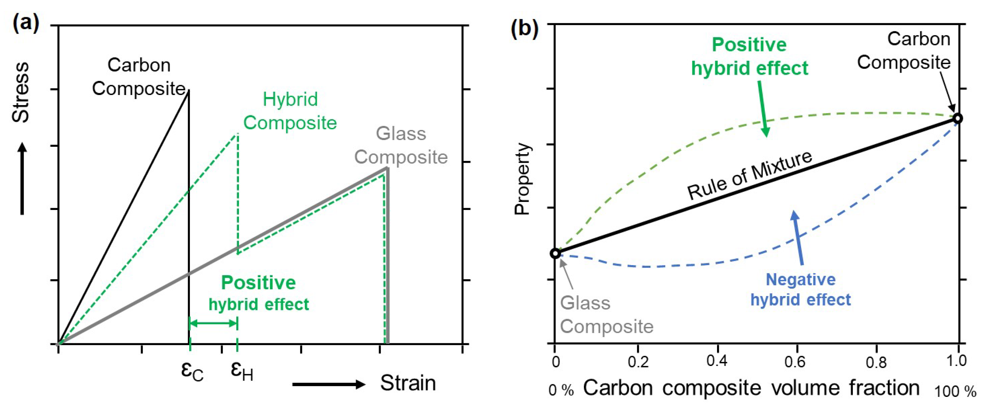
3.5. Hybrid Effect
3.5.1. Improvement in Failure Strain
3.5.2. Deviation from Rule of Mixtures (RoM)
4. Conclusions
- Altered dispersion of tows due to blocking of carbon and glass tows in H1, H2 and H3 hybrid composite did not affect the tensile and compressive stiffness of composites. The interply hybrid I1 demonstrates lower stiffness, about 16.7% and 9.4% lower than the average for intraply hybrids in tensile and compressive loading conditions, respectively.
- Failure of composites in tension and compression was catastrophic for both hybrids and non-hybrid composites. For hybrid composite, the catastrophic failure can be attributed to the higher carbon fibre volume fraction () in these composites.
- Macroscopic and microscopic observations confirmed the failure mode in tension is dominated by carbon fibre failure. For intraply hybrids, delamination of the glass tows from the surface after the carbon failure was distinctly observed, while for interply hybrid a brush-like effect similar to carbon composite R1 was observed. The compression failure for interply hybrid I1 owing to its layup structure was observed to be most complex with several failure phenomenon occurring simultaneously leading to the final failure.
- For I1 in tensile loading, a positive hybrid effect of about +7.4% in failure strain was observed and this can be attributed to the reduced damage evolution in carbon layers because of constrains provided by glass layers. In compression, however, increased number of layers and complex failure mechanisms in compression led to a negative hybrid effect of −6.4% for I1 compressive failure strain.
- For hybrid composites, a synergistic effect is observed for strength in tension and compression when compared to the strength obtained by the rule of mixtures. The results demonstrate a positive synergy/hybrid effect for all intraply hybrids.
- For intraply hybrids, the effect of tow dispersion was demonstrated. It was observed that composite H3 (with three carbon and three glass tows blocked along width) has superior performance in tension and compression compared to H1 and H2. Hybrids H1, H2 and H3 show a synergistic effect (deviation from RoM) of +7.5%, +10.9% and +17.8% in tensile strength and +23.8%, +31.8% and +36.9% in compressive strength, respectively.
- The ratio of tensile to compressive strength is similar (about 1.9) for all intraply hybrids, and it is highest (2.3) for ply level hybrid I1, which can be attributed to the diminished compression performance of I1 hybrid. For similar , the tow level hybrids shows overall better performance in mechanical loading conditions when compared to the composites hybridised at ply level.
Author Contributions
Funding
Acknowledgments
Conflicts of Interest
Appendix A. Calculation of Tensile Strength of Hybrid Composite
Appendix B. Calculation of Hybrid Effect
References
- Kretsis, G. A review of the tensile, compressive, flexural and shear properties of hybrid fibre-reinforced plastics. Composites 1987, 18, 13–23. [Google Scholar] [CrossRef]
- Swolfs, Y.; Gorbatikh, L.; Verpoest, I. Fibre hybridisation in polymer composites: A review. Compos. Part Appl. Sci. Manuf. 2014, 67, 181–200. [Google Scholar] [CrossRef]
- Hayashi, T. On the improvement of mechanical properties of composites by hybrid composition. In Proceedings of the 8th Reinforced Plastics Group Conference, London, UK, 29 June 1977; Volume 22, p. 149. [Google Scholar]
- Summerscales, J. The Mechanical Properties of Carbon Fibre with Glass Fibre Hybrid Reinforced Plastics. Ph.D. Thesis, University of Plymouth, Plymouth, UK, 1983. [Google Scholar]
- Fischer, S.; Marom, G. The flexural behaviour of aramid fibre hybrid composite materials. Compos. Sci. Technol. 1987, 28, 291–314. [Google Scholar] [CrossRef]
- Phillips, M. Composition parameters for hybrid composite materials. Composites 1981, 12, 113–116. [Google Scholar] [CrossRef]
- Paran, S.M.R.; Abdorahimi, M.; Shekarabi, A.; Khonakdar, H.A.; Jafari, S.H.; Saeb, M.R. Modeling and analysis of nonlinear elastoplastic behavior of compatibilized polyolefin/polyester/clay nanocomposites with emphasis on interfacial interaction exploration. Compos. Sci. Technol. 2018, 154, 92–103. [Google Scholar] [CrossRef]
- Paran, S.M.R.; Naderi, G.; Javadi, F.; Shemshadi, R.; Saeb, M.R. Experimental and Theoretical Analyses on Mechanical Properties and Stiffness of Hybrid Graphene/Graphene Oxide reinforced EPDM/NBR nanocomposites. Mater. Today Commun. 2019, 22, 100763. [Google Scholar] [CrossRef]
- Yao, H.; Sui, X.; Zhao, Z.; Xu, Z.; Chen, L.; Deng, H.; Liu, Y.; Qian, X. Optimization of interfacial microstructure and mechanical properties of carbon fiber/epoxy composites via carbon nanotube sizing. Appl. Surf. Sci. 2015, 347, 583–590. [Google Scholar] [CrossRef]
- Bunsell, A.; Harris, B. Hybrid carbon and glass fibre composites. Composites 1974, 5, 157–164. [Google Scholar] [CrossRef]
- Saka, K.; Harding, J. A simple laminate theory approach to the prediction of the tensile impact strength of woven hybrid composites. Composites 1990, 21, 439–447. [Google Scholar] [CrossRef]
- Swolfs, Y.; Verpoest, I.; Gorbatikh, L. Recent advances in fibre-hybrid composites: Materials selection, opportunities and applications. Int. Mater. Rev. 2018, 64, 181–215. [Google Scholar] [CrossRef]
- Wisnom, M.R.; Czél, G.; Swolfs, Y.; Jalalvand, M.; Gorbatikh, L.; Verpoest, I. Hybrid effects in thin ply carbon/glass unidirectional laminates: accurate experimental determination and prediction. Compos. Part Appl. Sci. Manuf. 2016, 88, 131–139. [Google Scholar] [CrossRef]
- Tavares, R.P.; Melro, A.R.; Bessa, M.A.; Turon, A.; Liu, W.K.; Camanho, P.P. Mechanics of hybrid polymer composites: Analytical and computational study. Comput. Mech. 2016, 57, 405–421. [Google Scholar] [CrossRef]
- Guerrero, J.; Mayugo, J.; Costa, J.; Turon, A. A 3D Progressive Failure Model for predicting pseudo-ductility in hybrid unidirectional composite materials under fibre tensile loading. Compos. Part Appl. Sci. Manuf. 2018, 107, 579–591. [Google Scholar] [CrossRef]
- Jalalvand, M.; Czél, G.; Wisnom, M.R. Numerical modelling of the damage modes in UD thin carbon/glass hybrid laminates. Compos. Sci. Technol. 2014, 94, 39–47. [Google Scholar] [CrossRef]
- Mesquita, F.; Swolfs, Y.; Lomov, S.V.; Gorbatikh, L. Ply fragmentation in unidirectional hybrid composites linked to stochastic fibre behaviour: A dual-scale model. Compos. Sci. Technol. 2019, 181, 107702. [Google Scholar] [CrossRef]
- Bunsell, A.; Gorbatikh, L.; Morton, H.; Pimenta, S.; Sinclair, I.; Spearing, M.; Swolfs, Y.; Thionnet, A. Benchmarking of strength models for unidirectional composites under longitudinal tension. Compos. Part Appl. Sci. Manuf. 2018, 111, 138–150. [Google Scholar] [CrossRef]
- You, Y.J.; Park, Y.H.; Kim, H.Y.; Park, J.S. Hybrid effect on tensile properties of FRP rods with various material compositions. Compos. Struct. 2007, 80, 117–122. [Google Scholar] [CrossRef]
- Zhang, J.; Chaisombat, K.; He, S.; Wang, C.H. Hybrid composite laminates reinforced with glass/carbon woven fabrics for lightweight load bearing structures. Mater. Des. (1980–2015) 2012, 36, 75–80. [Google Scholar] [CrossRef]
- Ren, P.; Zhang, Z.; Xie, L.; Ren, F.; Jin, Y.; Di, Y.; Fang, C. Hybrid effect on mechanical properties of M40-T300 carbon fiber reinforced Bisphenol A Dicyanate ester composites. Polym. Compos. 2010, 31, 2129–2137. [Google Scholar] [CrossRef]
- Hwang, S.F.; Mao, C.P. Failure of delaminated interply hybrid composite plates under compression. Compos. Sci. Technol. 2001, 61, 1513–1527. [Google Scholar] [CrossRef]
- Yerramalli, C.S.; Waas, A. Compressive behavior of hybrid composites. In Proceedings of the 44th AIAA/ASME/ASCE/AHS/ASC Structures, Structural Dynamics, and Materials Conference, Norfolk, VA, USA, 7–10 April 2003; p. 1509. [Google Scholar]
- Manders, P.W.; Bader, M. The strength of hybrid glass/carbon fibre composites. J. Mater. Sci. 1981, 16, 2246–2256. [Google Scholar] [CrossRef]
- Pandya, K.S.; Veerraju, C.; Naik, N. Hybrid composites made of carbon and glass woven fabrics under quasi-static loading. Mater. Des. 2011, 32, 4094–4099. [Google Scholar] [CrossRef]
- Peijs, A.; Catsman, P.; Govaert, L.; Lemstra, P. Hybrid composites based on polyethylene and carbon fibres Part 2: influence of composition and adhesion level of polyethylene fibres on mechanical properties. Composites 1990, 21, 513–521. [Google Scholar] [CrossRef]
- Jesthi, D.K.; Nayak, R.K. Improvement of mechanical properties of hybrid composites through interply rearrangement of glass and carbon woven fabrics for marine application. Compos. Part Eng. 2019, 168, 467–475. [Google Scholar] [CrossRef]
- Ikbal, M.H.; Ahmed, A.; Qingtao, W.; Shuai, Z.; Wei, L. Hybrid composites made of unidirectional T600S carbon and E-glass fabrics under quasi-static loading. J. Ind. Text. 2017, 46, 1511–1535. [Google Scholar] [CrossRef]
- Hasan, M.; Abdkader, A.; Cherif, C.; Spennato, F. Fibre hybrid composites consisting of discontinuous waste carbon fibre and continuous glass filaments developed for load-bearing structures with improved impact strength. Compos. Part Appl. Sci. Manuf. 2019, 126, 105610. [Google Scholar] [CrossRef]
- Pandya, K.S.; Pothnis, J.R.; Ravikumar, G.; Naik, N. Ballistic impact behavior of hybrid composites. Mater. Des. 2013, 44, 128–135. [Google Scholar] [CrossRef]
- Czél, G.; Jalalvand, M.; Wisnom, M.R. Design and characterisation of advanced pseudo-ductile unidirectional thin-ply carbon/epoxy–glass/epoxy hybrid composites. Compos. Struct. 2016, 143, 362–370. [Google Scholar] [CrossRef]
- Fan, W.; Dang, W.; Liu, T.; Li, J.; Xue, L.; Yuan, L.; Dong, J. Fatigue behavior of the 3D orthogonal carbon/glass fibers hybrid composite under three-point bending load. Mater. Des. 2019, 183, 108112. [Google Scholar] [CrossRef]
- Swolfs, Y. Perspective for Fibre-Hybrid Composites in Wind Energy Applications. Materials 2017, 10, 1281. [Google Scholar] [CrossRef]
- Fiore, V.; Di Bella, G.; Valenza, A. Glass–basalt/epoxy hybrid composites for marine applications. Mater. Des. 2011, 32, 2091–2099. [Google Scholar] [CrossRef]
- Shirvanimoghaddam, K.; Hamim, S.U.; Akbari, M.K.; Fakhrhoseini, S.M.; Khayyam, H.; Pakseresht, A.H.; Ghasali, E.; Zabet, M.; Munir, K.S.; Jia, S.; et al. Carbon fiber reinforced metal matrix composites: Fabrication processes and properties. Compos. Part Appl. Sci. Manuf. 2017, 92, 70–96. [Google Scholar] [CrossRef]
- ASTM D3800—16. Standard Test Method for Density of High–Modulus Fibers; ASTM International Standards Organization: West Conshohocken, PA, USA, 1999. [Google Scholar]
- ASTM D3171—99. Standard Test Methods for Constituent Content of Composite Materials; ASTM International Standards Organization: West Conshohocken, PA, USA, 1999. [Google Scholar]
- ISO 527-4:1997. Determination of Tensile Properties—Part 4: Test Conditions for Isotropic and Orthotropic Fibre-Reinforced Plastic Composites; International Organization for Standardization: Geneva, Switzerland, 1997. [Google Scholar]
- ISO 14126:1999. Fibre-Reinforced Plastic Composites–Determination of Compressive Properties in the In-Plane Direction; International Organization for Standardization: Geneva, Switzerland, 1999. [Google Scholar]
- GUM—Evaluation of Measurement Data—Guide to the Expression of Uncertainty in Measurement; JCGM 100:2008; Bureau International des Poids et Mesures: Sèvres, France, 1999; p. 134.
- Taketa, I. Analysis of Failure Mechanisms and Hybrid Effects in Carbon Fibre Reinforced Thermoplastic Composites. Ph.D. Thesis, KU Leuven, Leuven, Belgium, 2011. [Google Scholar]
- Ikbal, H.; Wang, Q.; Azzam, A.; Li, W. Effect of hybrid ratio and laminate geometry on compressive properties of carbon/glass hybrid composites. Fibers Polym. 2016, 17, 117–129. [Google Scholar] [CrossRef]
- Jones, R.M. Mechanics of Composite Materials; CRC Press: Boca Raton, FL, USA, 2014. [Google Scholar]


| Property | Units | T700S Carbon | E-CR Glass | LY 564 and Aradur 2954 |
|---|---|---|---|---|
| Density | [g cm−3] | 1.76–1.84 | 2.62 | 1.1 |
| fibre diameter | [μm] | 7 | 17 | – |
| Tensile strength | [MPa] | 4510 | 2400 | 71–77 |
| Tensile modulus | [GPa] | 221–240 | 81 | 2.5–2.6 |
| Failure strain | [%] | 1.9 | 4.9 | 4.5–5.5 |
| Composite Name | Fabric Used | Number of Layers | Layup Sequence | Thickness [mm] | Density [g cm−3] | FVF [%] | |
|---|---|---|---|---|---|---|---|
| Reference | R1 | Ref Carbon | 6 | [0/90/0]S | 1.8 | 1.5 | 49.4 |
| R2 | Ref Glass | 6 | [0/90/0]S | 1.2 | 1.8 | 47.1 | |
| Intraply | H1 | Hybrid1 (1C1G) | 6 | [0/90/0]S | 2.6 | 1.6 | 51.3 |
| H2 | Hybrid2 (2C2G) | 6 | [0/90/0]S | 2.6 | 1.6 | 54.1 | |
| H3 | Hybrid3 (3C3G) | 6 | [0/90/0]S | 2.6 | 1.6 | 51.8 | |
| Interply | I1 | Ref Carbon and Ref Glass | 12 (6+6) | [0G/0C/90G/90C/0G/0C]S | 3.1 | 1.6 | 50.4 |
| Property | Units | Ref Carbon | Hybrid1 | Hybrid2 | Hybrid3 | Ref Glass |
|---|---|---|---|---|---|---|
| Thickness at 400 g load | [mm] | 0.6 | 0.7 | 0.8 | 0.8 | 0.5 |
| Thickness at 28 kg load | [mm] | 0.4 | 0.6 | 0.6 | 0.5 | 0.3 |
| Areal density | [g m−2] | 327 | 520 | 516 | 521 | 260 |
| Coverage | [%] | 95 | 98 | 98 | 99 | 88 |
| Stitch gauge | [stitches/inch] | 10.1 | 9.8 | 9.7 | 9.6 | 9.9 |
| Stitch pitch | [stitches/inch] | 3.2 | 3.2 | 3.2 | 3.1 | 3.2 |
| Composites | Ultimate Tensile Strength | Tensile Failure Strain | Tensile Modulus |
|---|---|---|---|
| t [MPa] | t [%] | Et [GPa] | |
| R1–Ref carbon | 1165 (±43) | 1.70 (±0.04) | 69.8 (±2.1) |
| H1–Intraply (1C1G) | 935 (±58) | 1.60 (±0.10) | 60.8 (±3.0) |
| H2–Intraply (2C2G) | 964 (±43) | 1.67 (±0.10) | 59.3 (±1.2) |
| H3–Intraply (3C3G) | 1024 (±49) | 1.67 (±0.09) | 60.5 (±2.0) |
| I1–Interply | 898 (±44) | 1.82 (±0.10) | 50.2 (±0.8) |
| R2–Ref glass | 587 (±20) | 2.74 (±0.13) | 21.8 (±0.5) |
| Composites | Ultimate Compressive Strength | Compressive Strain | Compressive Modulus |
|---|---|---|---|
| c [MPa] | c [%] | Ec [GPa] | |
| R1–Ref carbon | 492 (±22) | 0.98 (±0.09) | 52.5 (±2.0) |
| H1–Intraply (1C1G) | 484 (±40) | 1.00 (±0.19) | 45.9 (±3.1) |
| H2–Intraply (2C2G) | 515 (±13) | 0.97 (±0.09) | 52,7 (±2.6) |
| H3–Intraply (3C3G) | 535 (±36) | 1.12 (±0.06) | 51.3 (±8.2) |
| I1–Interply | 388 (±16) | 0.91 (±0.08) | 45.3 (±2.5) |
| R2–Ref glass | 316 (±30) | 1.29 (±0.18) | 25.0 (±3.5) |
© 2020 by the authors. Licensee MDPI, Basel, Switzerland. This article is an open access article distributed under the terms and conditions of the Creative Commons Attribution (CC BY) license (http://creativecommons.org/licenses/by/4.0/).
Share and Cite
Rajpurohit, A.; Joannès, S.; Singery, V.; Sanial, P.; Laiarinandrasana, L. Hybrid Effect in In-Plane Loading of Carbon/Glass Fibre Based Inter- and Intraply Hybrid Composites. J. Compos. Sci. 2020, 4, 6. https://doi.org/10.3390/jcs4010006
Rajpurohit A, Joannès S, Singery V, Sanial P, Laiarinandrasana L. Hybrid Effect in In-Plane Loading of Carbon/Glass Fibre Based Inter- and Intraply Hybrid Composites. Journal of Composites Science. 2020; 4(1):6. https://doi.org/10.3390/jcs4010006
Chicago/Turabian StyleRajpurohit, Ashok, Sébastien Joannès, Vicky Singery, Philippe Sanial, and Lucien Laiarinandrasana. 2020. "Hybrid Effect in In-Plane Loading of Carbon/Glass Fibre Based Inter- and Intraply Hybrid Composites" Journal of Composites Science 4, no. 1: 6. https://doi.org/10.3390/jcs4010006
APA StyleRajpurohit, A., Joannès, S., Singery, V., Sanial, P., & Laiarinandrasana, L. (2020). Hybrid Effect in In-Plane Loading of Carbon/Glass Fibre Based Inter- and Intraply Hybrid Composites. Journal of Composites Science, 4(1), 6. https://doi.org/10.3390/jcs4010006