Article

Effect of Submicron Glass Fiber Modification on Mechanical Properties of Short Carbon Fiber Reinforced Polymer Composite with Different Fiber Length

1
Department of Mechanical and Systems Engineering, Graduate school/Faculty of Science and Engineering, Doshisha University, Kyotanabe, Kyoto 602-8580, Japan
2
DIC Corporation, DIC Building, 7-20, Nihonbashi 3-chome, Chuo-ku, Tokyo 104-8404, Japan
*
Author to whom correspondence should be addressed.
J. Compos. Sci. 2020, 4(1), 5; https://doi.org/10.3390/jcs4010005
Submission received: 28 October 2019 / Revised: 15 December 2019 / Accepted: 25 December 2019 / Published: 2 January 2020

Abstract

:
In this research, three kinds of carbon fiber (CF) with lengths of 1, 3, and 25 mm were prepared for processing composite. The effect of submicron glass fiber addition (sGF) on mechanical properties of composites with different CF lengths was investigated and compared throughout static tests (i.e., bending, tensile, and impact), as well as the tension-tension fatigue test. The strengths of composites increased with the increase of CF length. However, there was a significant improvement when the fiber length changed from 1 to 3 mm. The mechanical performance of 3 and 25 mm was almost the same when having an equal volume fraction, except for the impact resistance. Comparing the static strengths when varying the sGF content, an improvement of bending strength was confirmed when sGF was added into 1 mm composite due to toughened matrix. However, when longer fiber was used and fiber concentration was high, mechanical properties of composite were almost dependent on the CF. Therefore, the modification effect of matrix due to sGF addition disappeared. In contrast to the static strengths, the fatigue durability of composites increased proportionally to the content of glass fiber in the matrix, regardless to CF length.

1. Introduction

Fiber-reinforced composites have been developed over several decades and are widely used in many industrial applications such as the automotive, electronic, and marine industries. Composite materials are classified by the type of matrix, type of reinforced fiber, and morphology of reinforcement. Among them, short carbon fiber-reinforced polymer composites are gathering attention recently because of their ease of fabrication, economic benefits, and also their superior mechanical properties [1,2,3,4,5,6]. They can fill the mechanical property gap between the continuous-fiber laminates used as primary structures by the aircraft and aerospace industry and the unreinforced polymers used in partial-load-bearing applications [7]. Moreover, thermoset matrices such as vinyl ester resin (VE) have higher thermal stability in comparison with thermoplastics, and therefore they are more attractive in terms of industrial applications. Vinyl esters are unsaturated esters of epoxy resins, and the ester linkages are present only at the terminal ends of the chains. Consequently, they offer similar mechanical and in-service properties to those of the epoxy resins and equivalent processing techniques to those of the polyesters while being more flexible and having higher fracture toughness. VE resin also has good wettability, has strong resistance against acid and alkalis, cures at room temperature, has low moisture absorption, and has good mechanical properties [8,9,10,11]. Carbon fibers have low density (1.8–2.0 g/cm3). The tensile strength and tensile modulus exceed 6 GPa and 600 GPa, respectively. Therefore, they possess the highest specific stiffness and strength among the currently available fibers used to reinforce polymer composite [12,13]. For that reason, the combination of carbon fiber and vinyl ester has attracted the attention of researchers and has been considered as a potential material in industry and aviation [14]. One of the disadvantages of CF composites is the mechanical properties of short carbon fiber composites are still much lower in comparison to that of long fiber composites. Cracks easily occur on both ends of the fiber because (finite) short carbon fibers are used. Thereupon, it is difficult to achieve an excellent performance of short carbon fibers [2,15,16]. Some researchers have reported that modifying the matrix by nano- or micro-scale filler improves the fracture toughness of matrix and the fiber/matrix adhesion, delaying the initiation and propagation of cracks, and consequently increasing the mechanical properties of composites [17,18,19]. Takagaki et al. reported that an addition less than 0.8 wt% of MFC (micro fibrillated cellulose) to epoxy matrix of carbon fabric composites extended their fatigue life 10 times that of the unmodified case [20]. Xu et al. studied the effect of nano-clay modification of epoxy matrix on the mechanical properties of CF/EP composites. Their study showed that the mode-I interlaminar fracture toughness increased by 85% for 4 phr nano-clay, and the flexural strength increased by 38% for 2 phr nano-clay [21]. However, the nano filler shows high agglomeration because of its highly specific surface energy, and thus the filler is usually dispersed in liquids such as water. Nevertheless, the elimination of water from nano filler after dispersion is difficult and complicated. On the basis of these considerations, the submicron inorganic filler was selected for not only avoiding the agglomeration, but also bringing the advantage of utilizing modern polymer processing technologies [22,23].
In this study, the CF composites made from 1, 3, and 25 mm lengths of carbon fiber and vinyl ester resin modified by submicron glass fiber were prepared in order to investigate the effect of submicron glass fiber and carbon fiber length on the mechanical properties of composites.

2. Material and Processing

2.1. Material

The vinyl ester resin was supplied by DIC Corporation, Japan, and modified by submicron glass fiber (Nippon Muki Co., Ltd., Tokyo, Japan) with a diameter in the range of 0.4 to 2.4 µm and a length from 200 to 2000 µm. The carbon fibers (Yoshino Limited, Tokyo, Japan) of 1, 3, and 25 mm in length were used as the reinforcement. All materials were used without any further treatment.

2.2. Modification of VE Resin

The absorbed moisture of supplied submicron glass fiber addition (sGF) was eliminated by heating. After the drying process, the dried sGF and VE were mixed by the homogenizer at 5000 rpm for 30 min, and then the hardener and promoter were added. The degas process was conducted to the mixture by using a vacuum chamber. Hereinafter, samples were classified by using the weight ratio of sGF against VE. In this study, 0.0 (unmodified), 0.3, and 0.6 wt% of VE were prepared.

2.3. Fabrication of Composite

A thin aluminum plate covered by a non-stick film was put on a scale. At the beginning, a thin layer of resin was spread out on the surface of the film, followed by a layer of the carbon fiber. The weight of resin and fiber was controlled to achieve the desired ratio of fiber/matrix. The process was repeated until finishing the available materials. After that, the assembly of resin and CF was put into a ball mixer and mixed for 10 min with the aid of ceramic balls. Finally, the mixture was set onto a steel mold and pressed under 15 MPa for 3 h at 80 °C. After curing, the mold was gradually cooled down to room temperature, while applied pressure was kept constant. The post-cure process was conducted at 100 °C for 3 h. Higher viscosity caused by the insertion of shorter fiber length, making having the same volume fraction in the different composites impossible. Therefore, in this research, the volume fraction of fiber for 1, 3, and 25 mm composites was 25%, 35%, and 40%, respectively. For the sake of comparison, the strength/fiber volume ratio of each composite is used in latter sections.

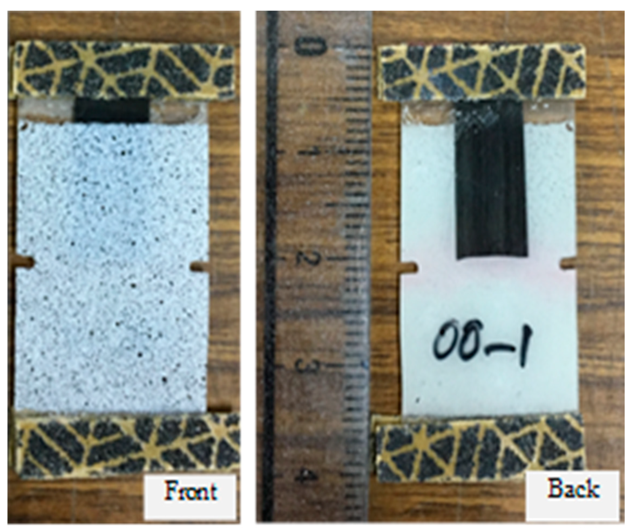
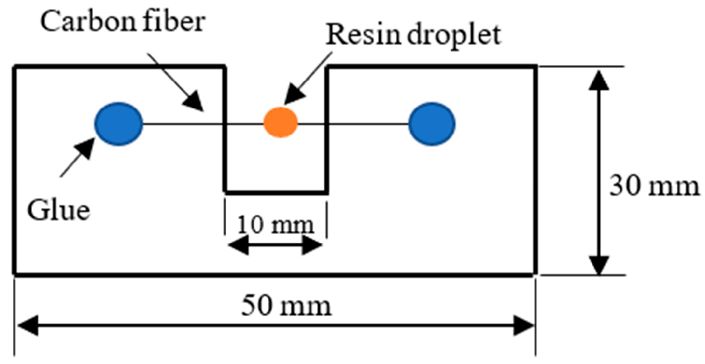
2.4. Evaluation of Adhesion Between Single Fiber and Matrix

The micro droplet test was conducted to evaluate the interfacial shear strength (IFSS) of the single fiber with the matrix. The droplets of liquid VE resin were first dropped on the single carbon fibers, which was attached onto the paper frames, then cured at 80 °C for 3 h and post cured at 100 °C for the same period of time. The embedded lengths of the droplets were measured by an optical microscope. The test was carried out by the microdroplet instrument (Model HM410 - Tohei Sangyo Corporation, Tokyo, Japan). The IFSS between single fiber and VE was calculated by the following equation:
τ = F/πdL
where τ is the IFSS, F is the maximum load, d is the fiber diameter, and L is embedded length of resin drop. The geometry of the frame containing the sample is shown in Figure 1.

2.5. Static Mechanical Characteristics

Three point bending test was conducted following the ASTM D790–03. The size of specimen was 100 × 15 × 2.5 mm3. The cross head speed was controlled to be 2 mm/min with a support length of 80 mm. The samples for tensile test were prepared following the ASTM D638 with a dimension of 200 × 25 × 2.5 mm3. The gage length was 100 mm and the speed of testing was controlled to be 1 mm/min. The Izod impact test was performed using a pendulum testing device according to the standard JIS 7062 with the specimen being 65 × 10 × 4.5 mm3 in size. The test was conducted when the hammer impacted the flattened surface of the specimen. At least 5 specimens were used for each kind of sample for flexural and tensile test, whereas 10 specimens were used for the impact test.

2.6. Measuring Strain Distribution of Model Specimen

To observe the strain distribution around the carbon fiber tip of CF, a model composite was prepared. CF 25 mm in length was embedded into VE, cured at 80 °C for 3 h, then post cured at 100 °C for the same amount of time. Pre-cracks with an approximate crack length of 1.5 mm were prepared by a diamond cutter at both sides, then natural cracks were introduced by slicing a razor at the pre-crack root before testing. A white and black speckle pattern was painted in the sample surfaces for digital image correlation analysis (Figure 2). The sample size was 40 × 20 × 0.5 mm3. The tensile load was applied to the model specimen at a constant cross head speed of 1 mm/min.

2.7. Fatigue Test

The tension-tension fatigue test was conducted on a hydraulic testing machine under a load-controlled condition. A cyclic sinusoidal load with 5 Hz of frequency and stress ratio of 0.1 was applied. In this study, the test was truncated when the number cycles exceeded 106. The maximum applied stress was set to be approximately 50% of the average ultimate tensile strength. The sample size was the same as that of tensile coupons.

3. Results and Discussion

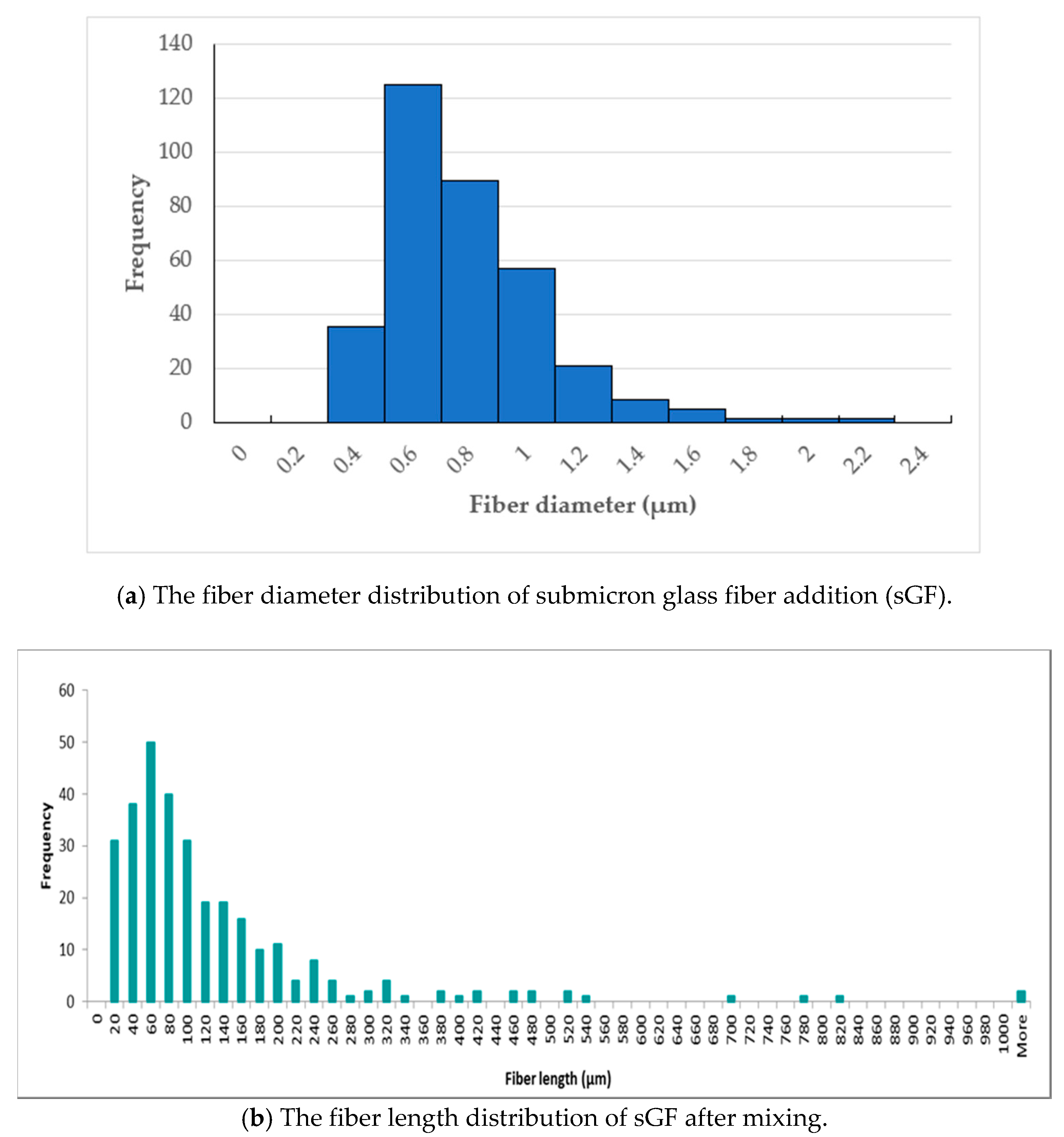
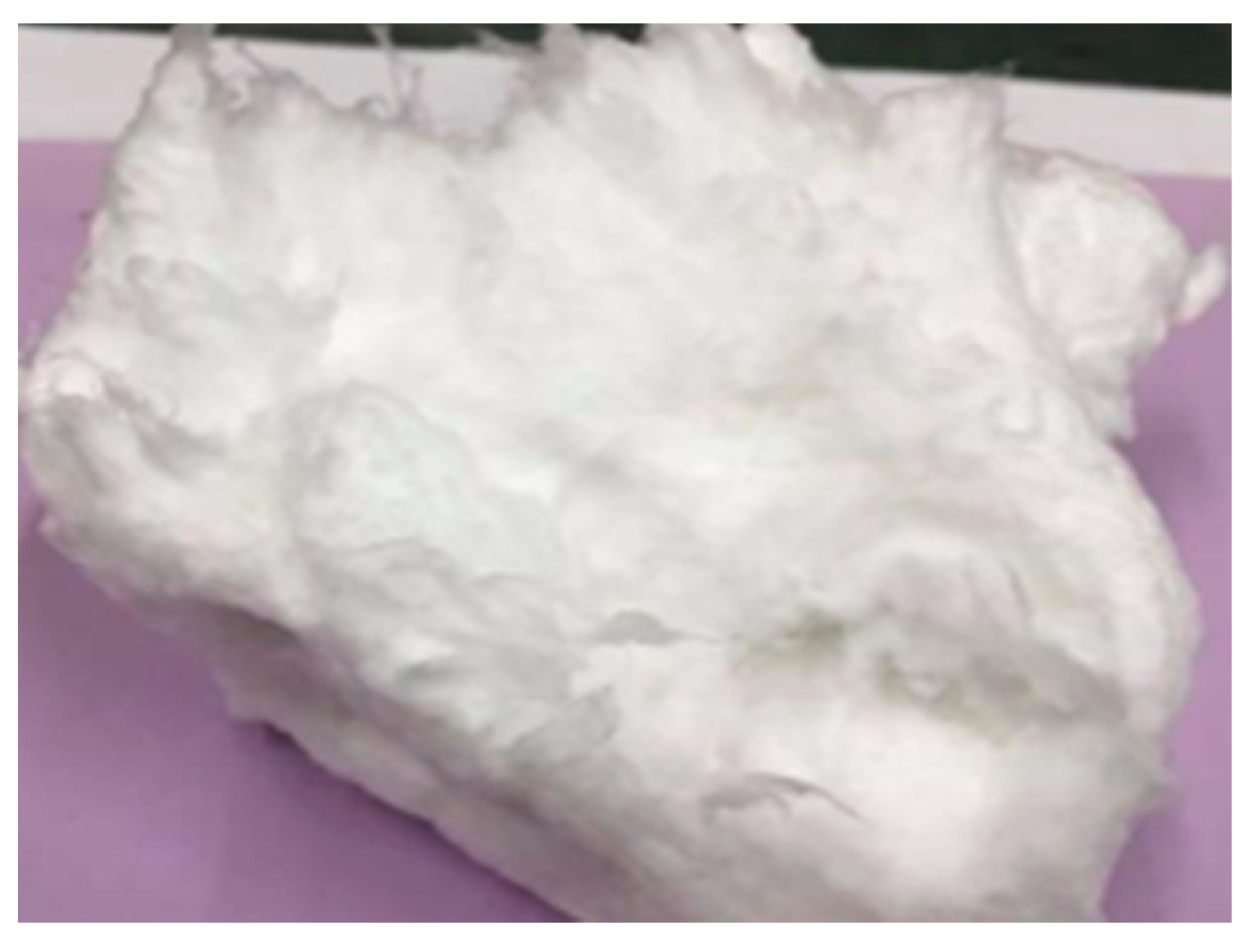
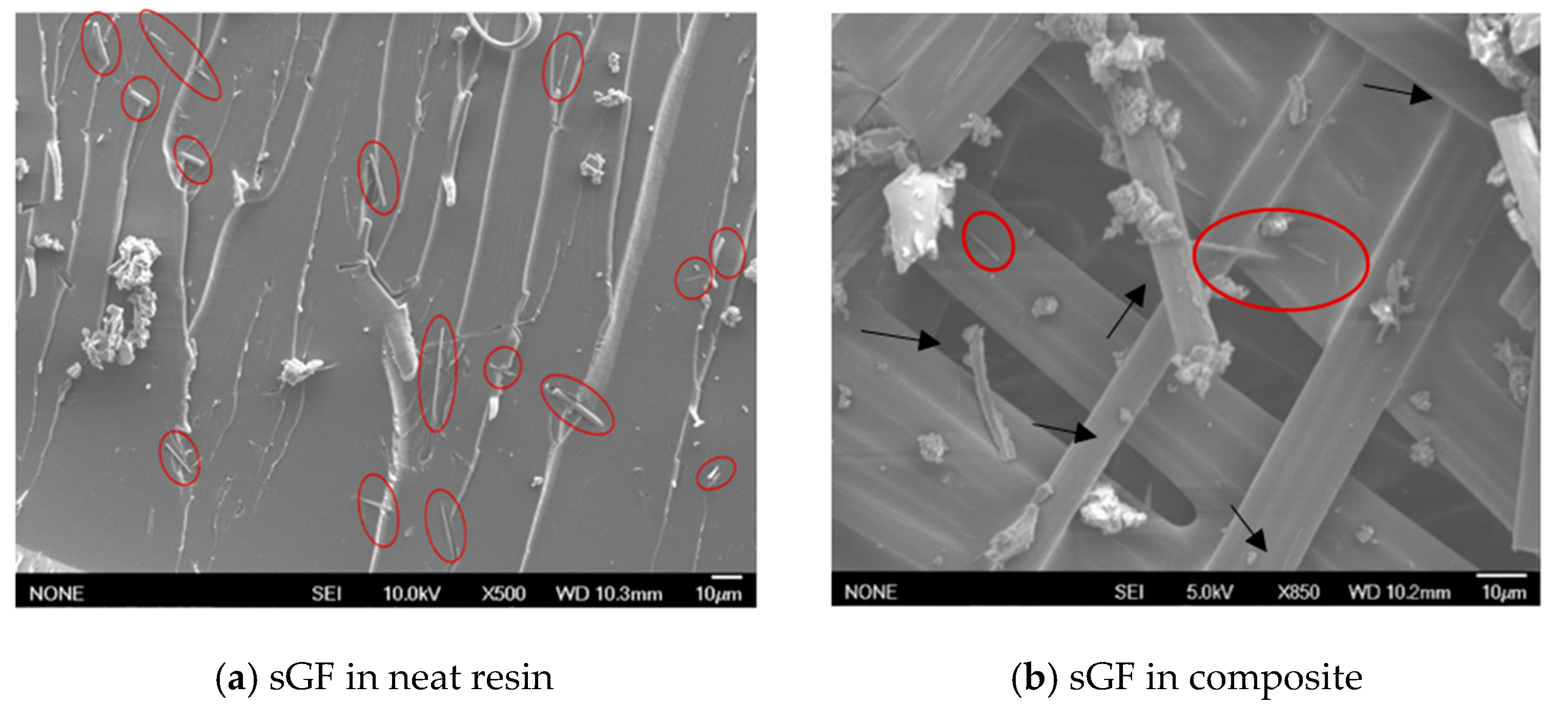
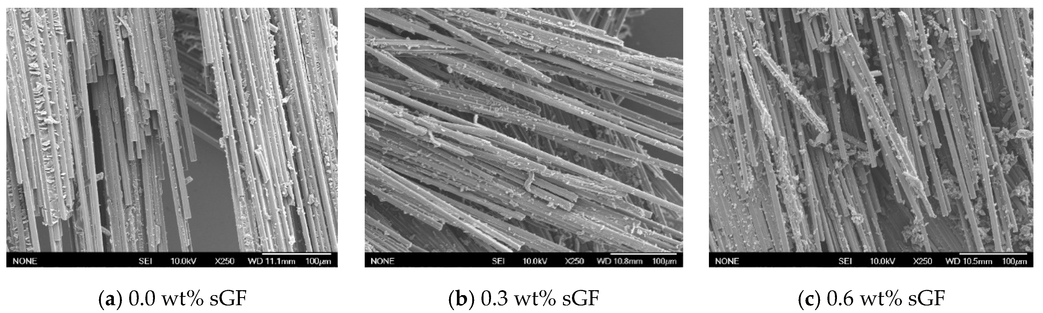
3.1. Added sGF in Resin and Composite

To indentify the length of sGF after mixing process, the mixture of resin and modifier was diluted in acetone, and then all the excess resin was removed through a filter paper by applying the vacuum. The images of collected sGF after filtrating were taken by SEM equipment to measure the length of 300 individual fibers. The result was used to build the histogram plot of fiber length distribution of glass fiber.
Figure 3a shows the diameter distribution of glass fiber before mixing, whereas Figure 3b indicates the majority of fibers having a length in the range of 20 to 200 µm, a minority of them having an excessively large length up to around 1 mm. Assuming that the diameters of sGF were not affected during sample process, the aspect ratio of sGF was found to be in the wide range. The SEM pictures confirm that the sGFs were well dispersed in the matrix by the conventional mixing technique, as mentioned in Section 2.2, although the original fiber was in agglomeration form (see Figure 4 and Figure 5). Submicron filaments were separated from each other and distributed regularly without fiber curviness.

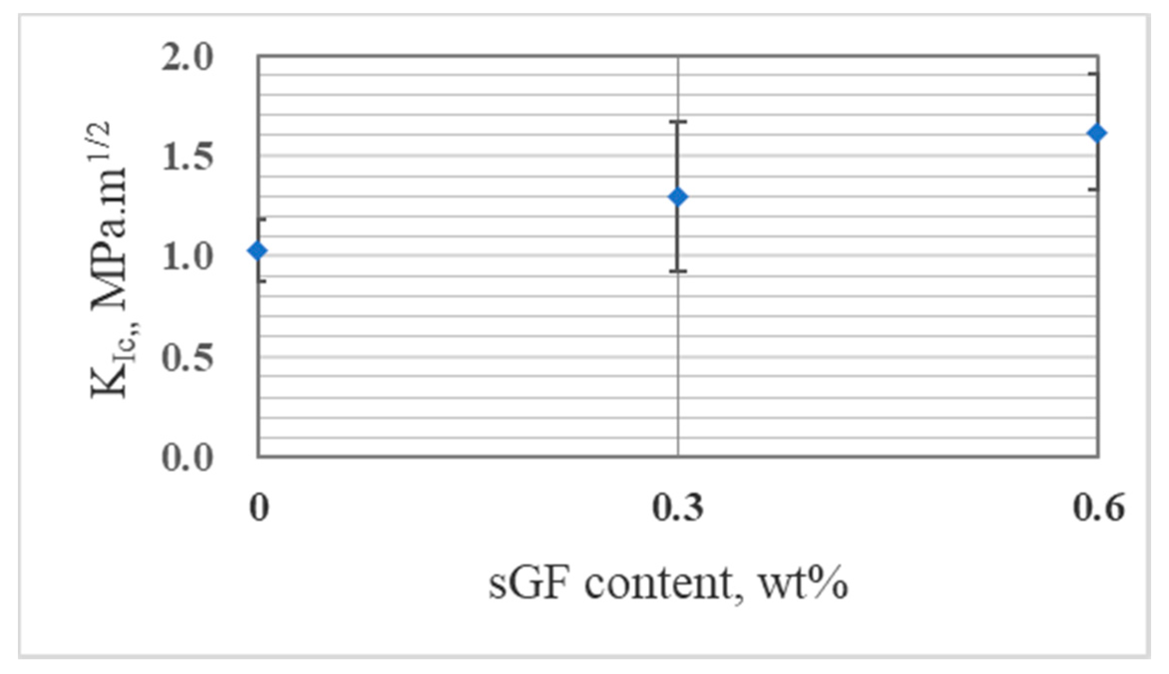
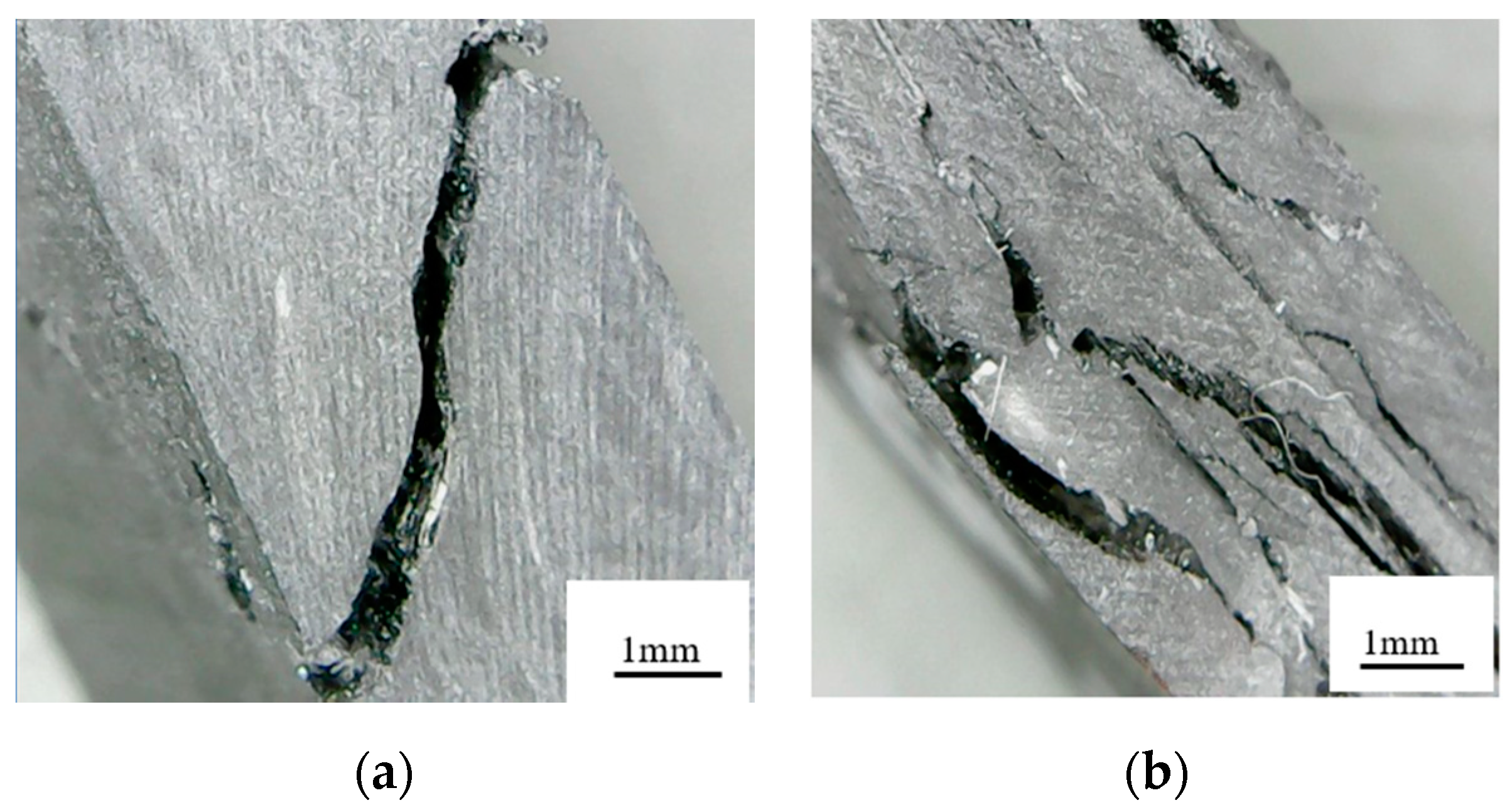
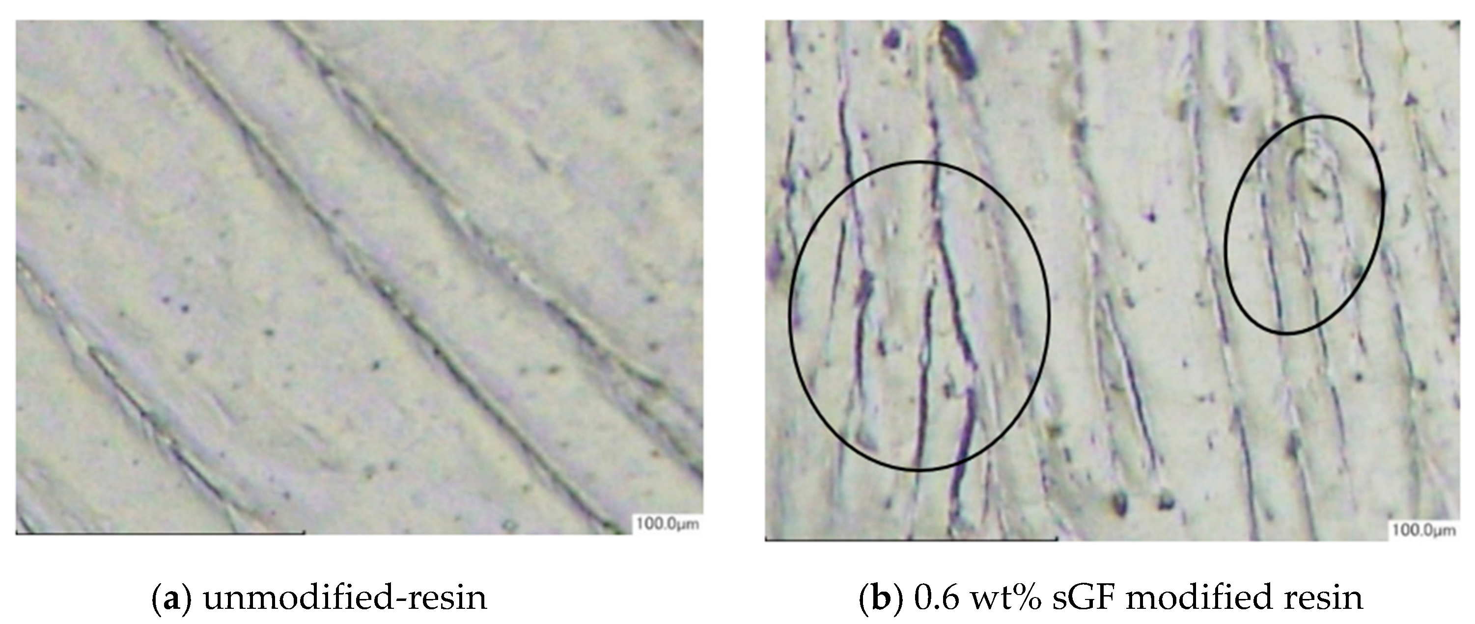
3.2. Fiber and Matrix Adhesion

As can be seen from Table 1, the interfacial shear strength (IFSS) of modified sample was almost similar to that of un-modified resin. This result indicated that the adhesion between fiber and matrix was not affected by the addition of submicron glass fiber. The SEM images of fracture surfaces of composites after tensile test also showed that there were no differences in fiber-matrix interfacial interaction in un-modified and modified-composites (see Figure 6).

3.3. Static Mechanical Characteristics

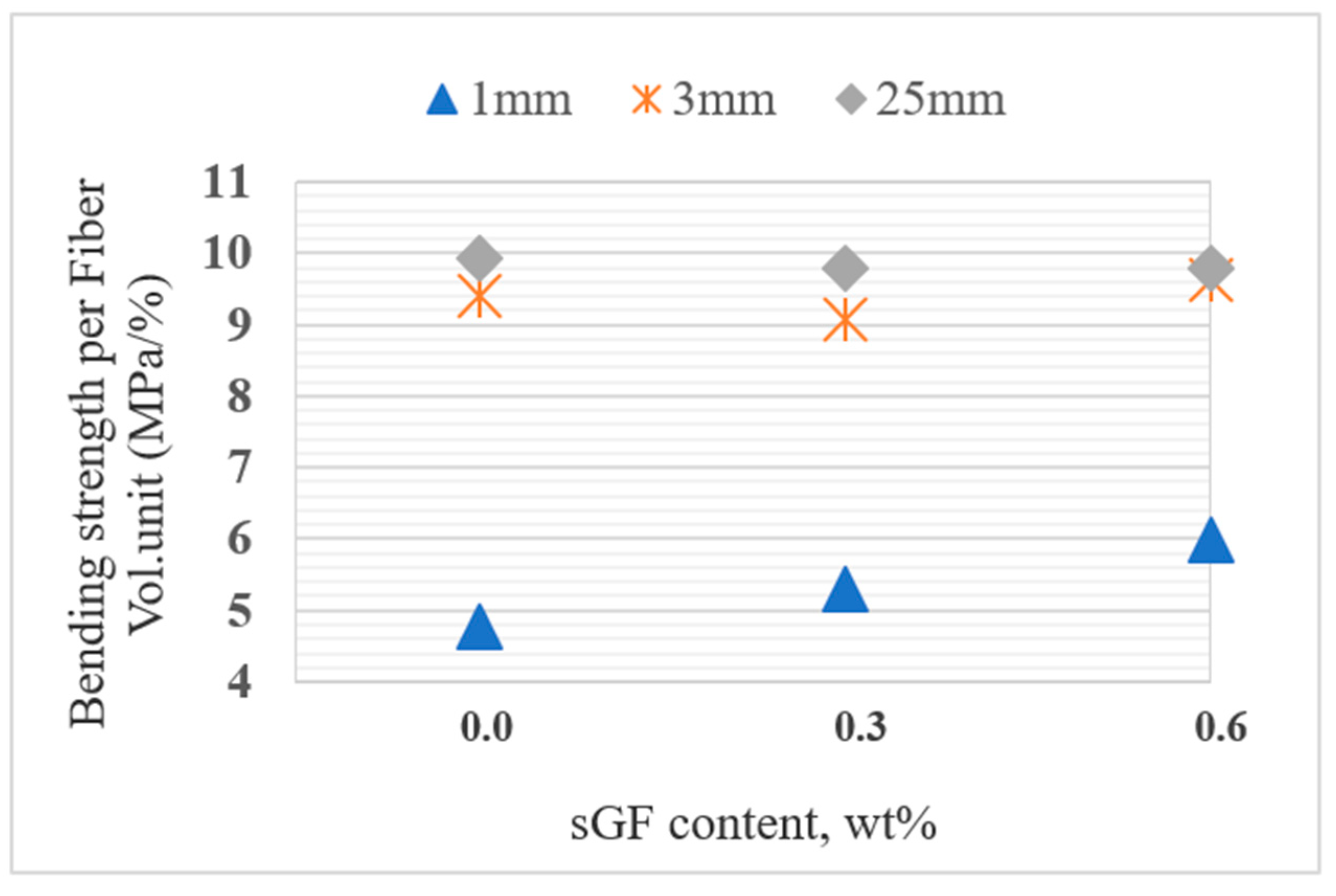
3.3.1. Bending Strength

Mechanical performance of short fiber composite often varies in a large range because of experimental scatter causing difficulties in predicting the effect of modifiers on filled-system [5]. Values in parentheses manifested large standard deviation of tested data of mechanical properties of composites (for example, see Table 2, Table 3). Table 2 and Figure 7 show the change of flexural strength of composites with respect to CF length corresponding to sGF content. The flexural strength of composites increased with an increase of CF length, as mentioned by Thomason [24]. However, the significant improvement of bending strength only happened when the fiber length changed from 1 to 3 mm. In the other words, the bending strength per fiber volume fraction of 3 and 25 mm composite was almost the same.
From the view point of sGF content, the flexural strength only improved by sGF addition when carbon fiber length was 1 mm long. Compared with the neat resin, reinforcing VE by 1 mm carbon fiber increased the flexural brittleness, resulting in the slight decrease of the bending strength of resin. Our previous research confirmed that modifying resin by glass fiber retained the bending strength of resin but considerably extended the fracture toughness [25] (see Figure 8). Therefore, the enlargement of bending strength in 1 mm modified composites might be due to the toughened matrix. However, effect of sGF addition was limited in the case of longer fiber composite (3 and 25 mm) with higher content of carbon fiber. This can be explained by the leading behavior of fiber in 3 mm composite and 25 mm composite being more superior than that of the matrix. Therefore, matrix modification does not affect the mechanical performance of these composites.
Figure 9, Figure 10 and Figure 11 show the bending stress-bending strain diagram of composites made from 1, 3, and 25 mm long CF, respectively. Regardless of the difference of CF length and sGF content, the bending stress linearly increased until fracture in most of the specimens. Test results also showed that the flexural modulus of composites were almost the same, even if the sGF was added, with the exception of 1 mm composite presenting a marginal increase.
Images of the fractured region of 1 and 25 mm composites after the test taken by the digital microscope are shown in Figure 12. In 1 mm composite, the cracks appeared in the thickness direction. By contrast, cracks propagated in longitudinal (inter-laminar) direction in the 25 mm composite. These results suggest that the cracks propagated through CF tips in the 1 mm composite, but along the fiber in the longer fiber composite.

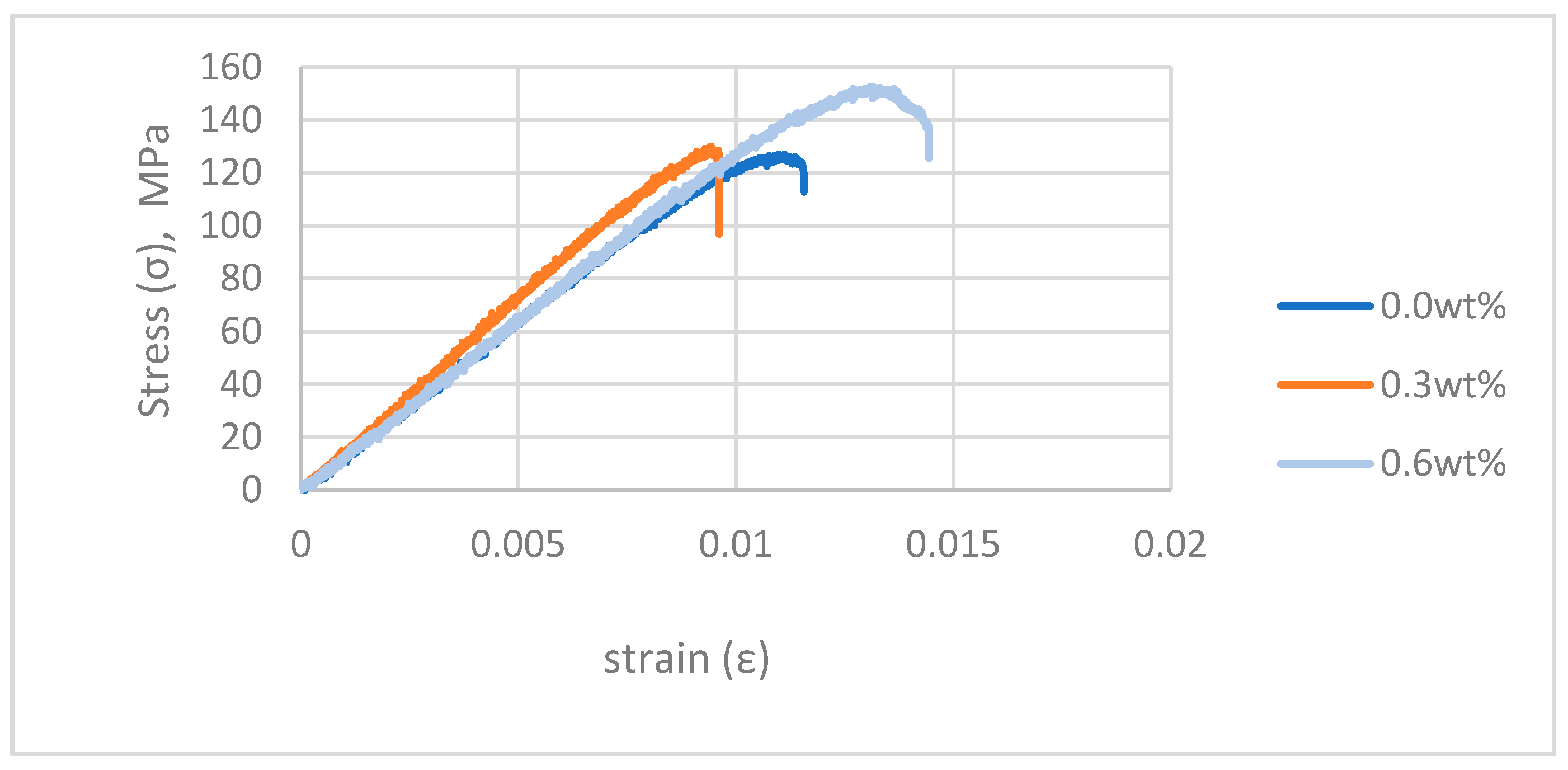
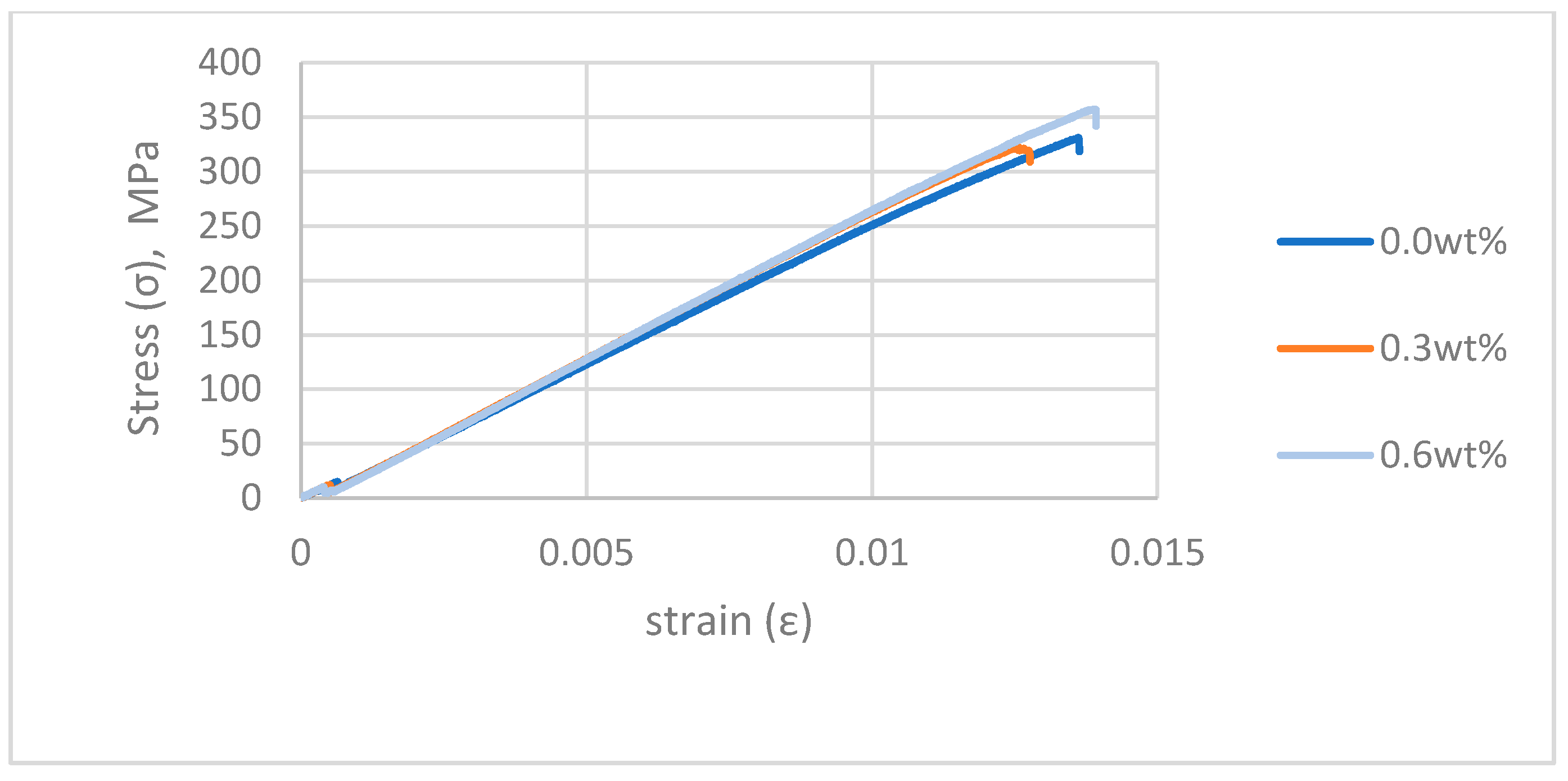
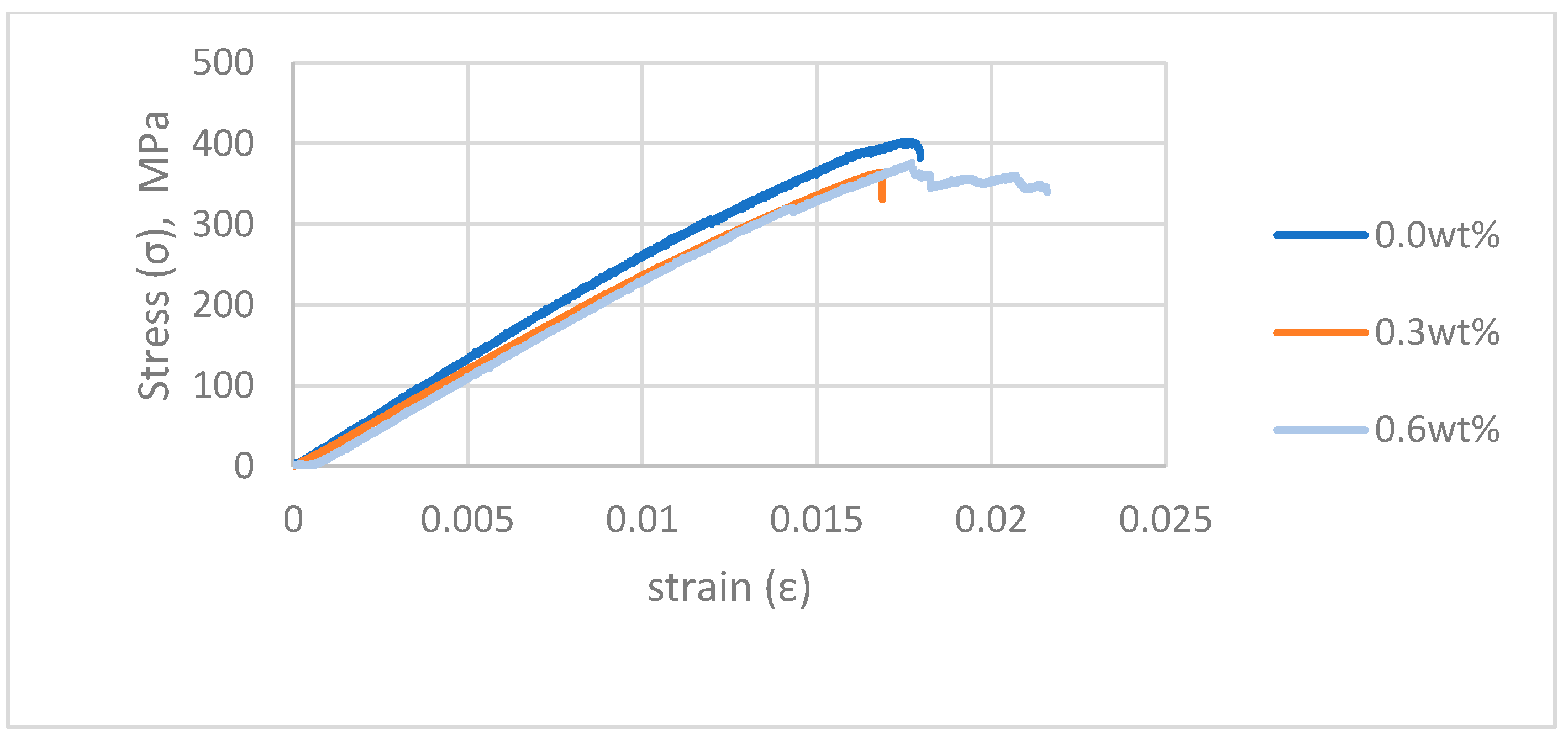
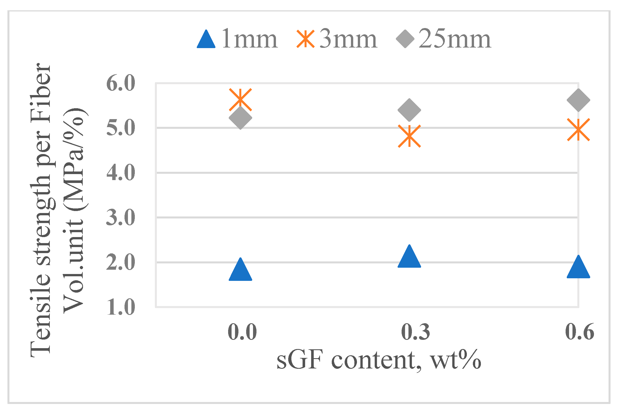
3.3.2. Tensile Strength

The same tendency with the flexural strength can be noticed in the tensile strength (Table 3 and Figure 13). For the same volume fraction of fiber, 3 mm composite and 25 mm composite also had similar tensile performance. Table 4 compares flexural and tensile strength of un-modified composites at different lengths (i.e., 1 mm, 2 mm, 3mm, and 25 mm). The results suggest that 3 mm can be considered as the “critical fiber length” of the composite in this research. Adding CF 1 mm into matrix at 25% fiber volume fraction significantly reduced the tensile strength of resin. The tensile strength of this composite fell to approximately 63% compared to that of neat resin. The addition of sGF could not compensate for this degradation, as the longitudinal tensile strength of composite materials is determined mostly by the strength and volume content of the fiber reinforcement [26].

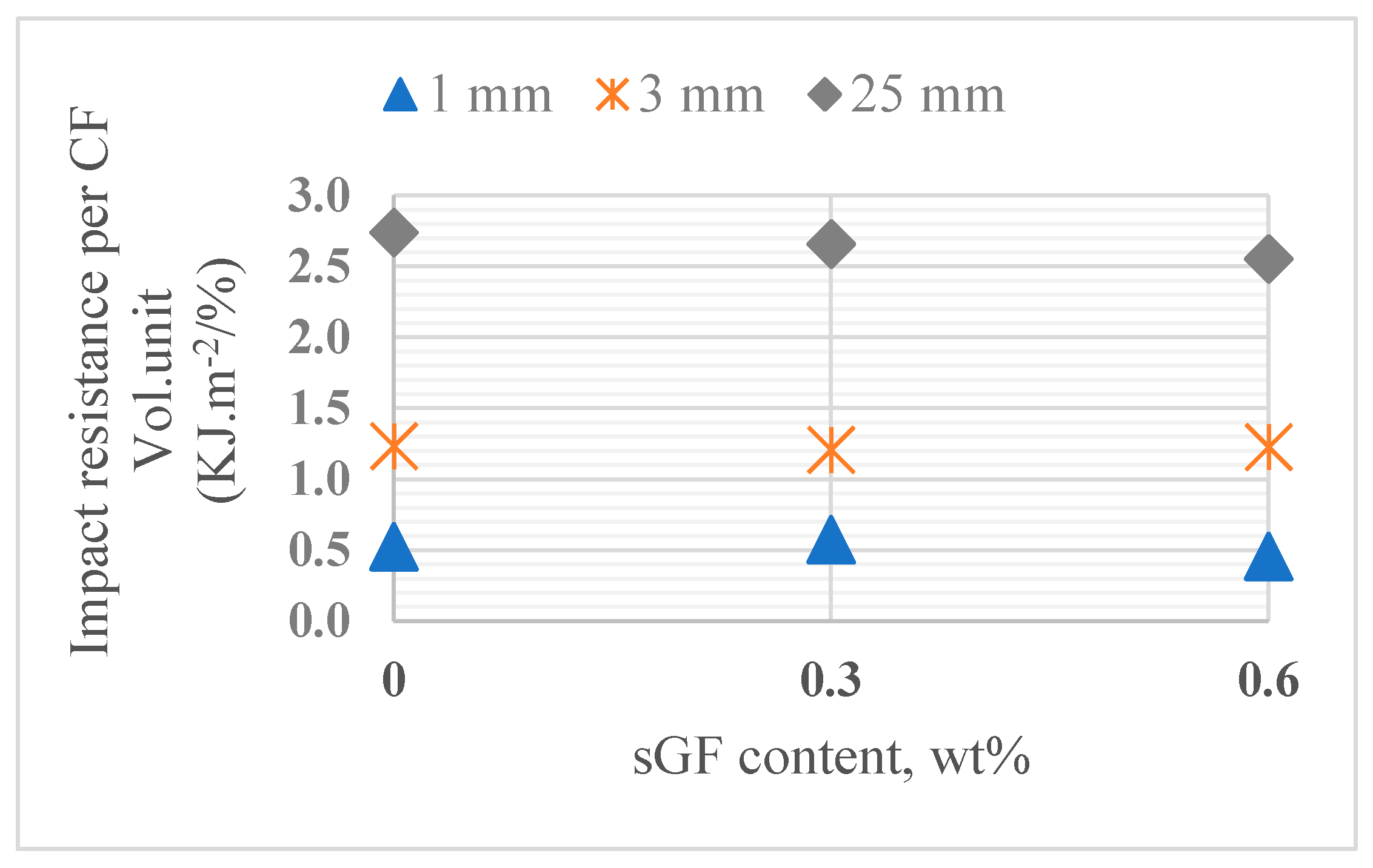
3.3.3. The Impact Resistance of Composites

Figure 14 and Table 5 show the Izod impact resistance of neat resin and composites. The impact resistance of composite 1 mm also declined in comparison with that of the neat matrix. In contrast to the bending and tensile strength, the impact resistance performance of composite improved proportionally with the increase of fiber length. However, adding glass fiber into the matrix did not affect the energy absorption ability of the composites.
Figure 15 shows the edge cracks of specimens after impact test. The crack formation in these cases is similar to that of the bending strength test. Cracks propagated in the zig-zag form in 25 mm composite but were much straighter in the 1 mm composite.

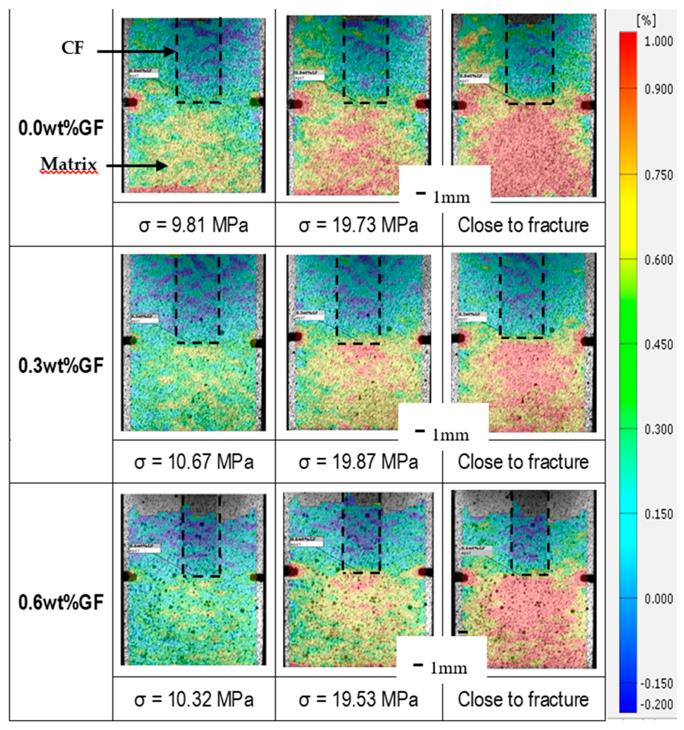
3.4. Strain Distribution around the Carbon Fiber Tip

Figure 16 shows the strain distribution along the longitudinal direction of model composites under the same level of tensile load. In this figure, the position of embedded carbon fiber bundle is illustrated in black dash lines. The test results indicated that the strain around the carbon fiber bundle tip and pre-crack increased with the increase of applied stress level. However, when the matrix was modified with sGF, the strain concentration was suppressed. These results suggest that the existence of added sGF is helpful in avoiding stress concentration at the carbon fiber tip.

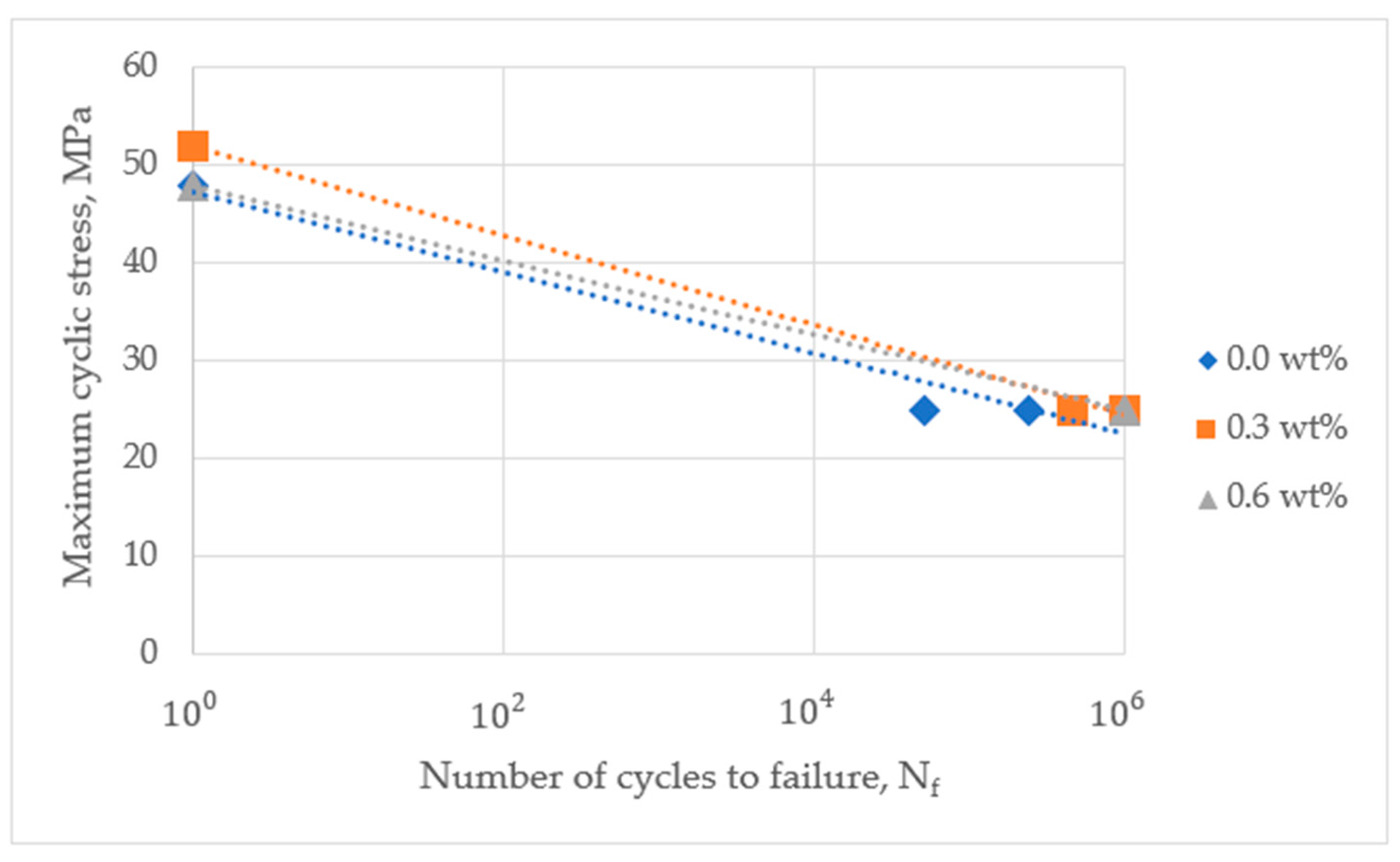
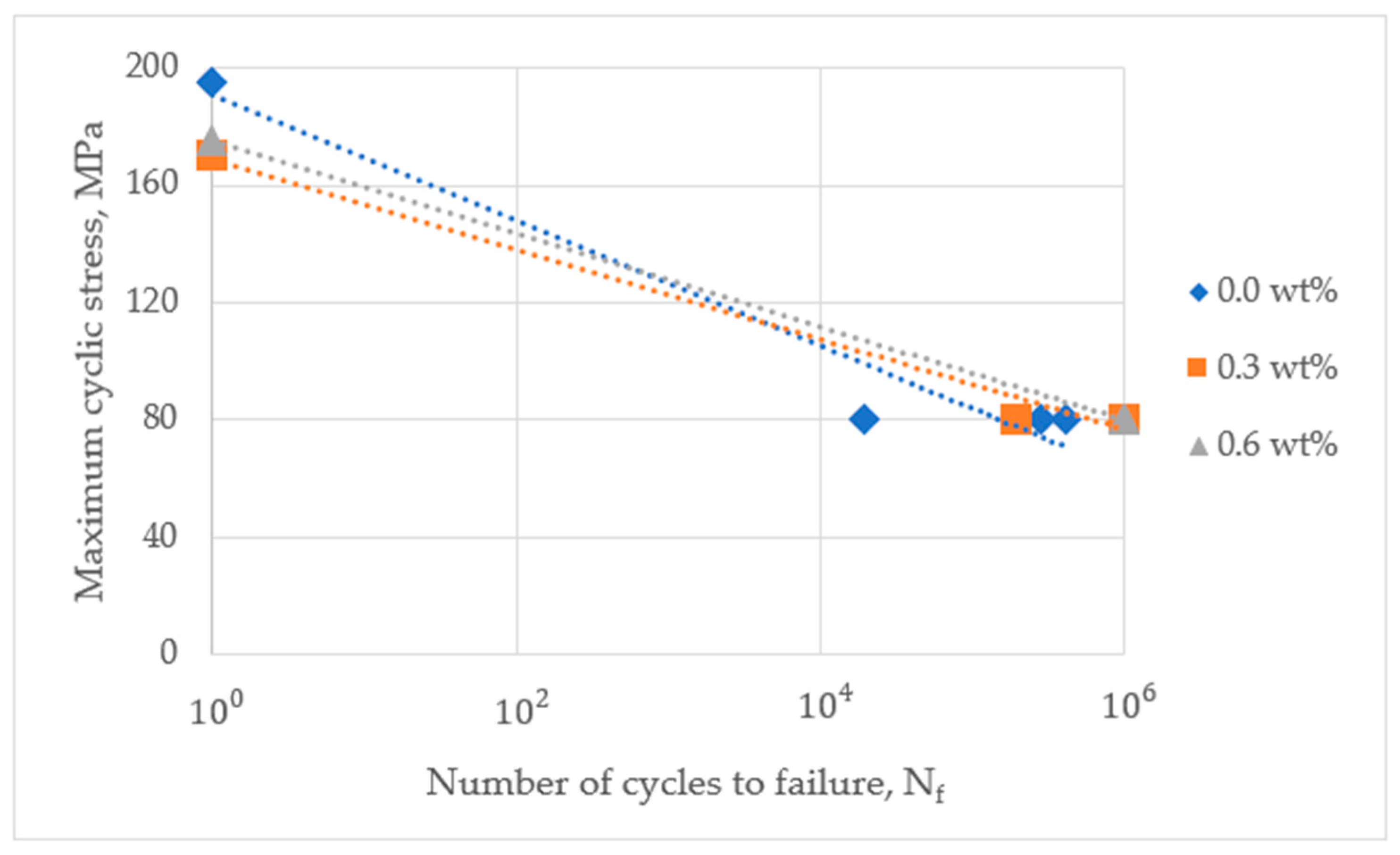
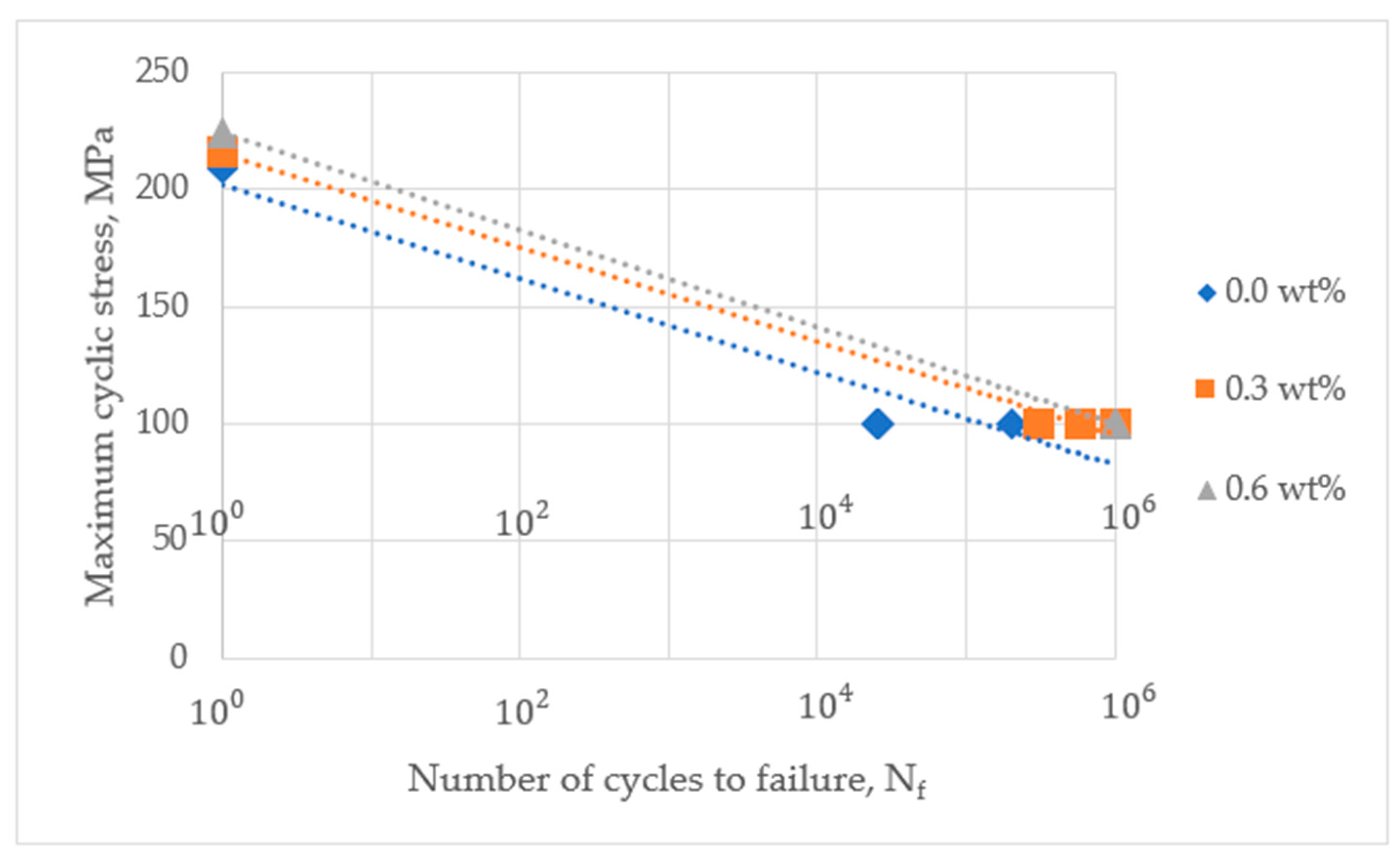
3.5. Effect of sGF Addition on the Fatigue Life

Figure 17, Figure 18 and Figure 19 show the number of cycles to failure of the composites with respect to fiber length. For all cases of fiber length, the fatigue life noticeably extended with the addition of sGF. The increment of cycles to failure was proportional to the content of glass fiber in matrix, regardless of the fiber length. In particular, at 0.6 wt% of modifier, all specimens survived over 1 million cycles. The strain distribution test suggested that sGF prevented the concentration of stress around carbon fiber tips as a result, delaying the propagation of micro-cracks inside the matrix. In our previous research, the number of cycles to failure in the test of compact tension of modified resin also remarkably improved thanks to the addition of glass fiber [26]. Therefore, the enlargement of fatigue life in composites was due to the presence of sGF dissipating energy for deflecting and delaying the propagation of micro-cracks (see Figure 20).
Failure under static loading condition occurred at very high rate compared to that of cyclic loading. Therefore, the delaying effect of crack propagation of sGF can be hidden or skipped under static condition, as sGF particles do not have enough time for absorbing partly failure energy. In other words, this suggests that sGF brings into play an improvement in strength for composites under the cyclic loading applications.

4. Conclusions

Mechanical properties of short carbon fiber composite modified by submicron glass fiber were investigated under static and cyclic loading conditions. The results are summarized as follows:
1. The sGF was well-dispersed in the VE matrix by using the conventional homogenizer at the speed of 5000 rpm for 30 min. The aspect ratio of glass fiber after mixing changed over a wide of range.
2. The mechanical performance of composites increased with an increase of fiber length, showing significant improvement when fiber length lifted from 1 mm up to 3 mm. However, the bending and tensile strength of 3 and 25 mm were nearly the same when possessing the same volume fraction. This suggests that 3 mm can be considered as “the critical fiber length” in the composite of this research and the potential alternative for longer fibers in some restricted industrial applications. Regarding sGF modification, the effect of the addition of glass fiber can be observed in the case of the 1 mm long fiber and low fiber volume fraction thanks to the improvement of fracture toughness of resin. In other words, modifying the matrix by sGF cannot achieve an improvement in the case of higher fiber concentration and longer fiber because the fiber dictates the behavior in the composite.
3. For all cases of fiber length, the fatigue life of composite remarkably improved with the addition of sGF. The increment of cycles to failure was proportional to the content of glass fiber in matrix, regardless of the fiber length. In particular, at 0.6 wt% of modifier, all specimens survived over 1 million cycles. The strain distribution test with model specimens suggested that sGF delayed the propagation of micro-cracks, resulting in more energy dissipation and, finally, the improvement of the fatigue life of modified composites.

Author Contributions

Methodology: F.T., O.K. (Okubo Kazuya), O.K. (Obunai Kiyotaka), F.Y., S.O., T.H. Validation: O.K. (Obunai Kiyotaka), N.T.T.N. Formal analysis: O.K. (Obunai Kiyotaka), N.T.T.N. Investigation: N.T.T.N. Writing—original draft preparation: N.T.T.N. Supervision: F.T., O.K. (Okubo Kazuya), O.K. (Obunai Kiyotaka). Project administration: O.K. (Okubo Kazuya), O.K. (Obunai Kiyotaka), F.Y., S.O., T.H. All authors have read and agreed to the published version of the manuscript.

Funding

This work was partially supported by JSPS KAKENHI grant number 18H01343.

Acknowledgments

The authors gratefully acknowledge Nippon Muki Co., Ltd. for the financial and material supports provided to this research, and former master’s student Tran Thi Thuy Dung for supporting experiments.

Conflicts of Interest

The authors declare no conflict of interest.

References

  1. Koniuszewska, A.G.; Kaczmar, J.W. Application of polymer based composite materials in transportation. Prog. Rubber Plast. Recycl. Technol. 2016, 32, 1–24. [Google Scholar] [CrossRef]
  2. Cantor, K.M.; Watts, P. Plastics Processing. In Applied Plastics Engineering Handbook, 2nd ed.; Kutz, M., Ed.; William Andrew: New York, NY, USA, 2016; Volume 2, pp. 195–203. [Google Scholar]
  3. Park, S.J.; Seo, M.K. Composite characterization. Interface Sci. Technol. 2011, 18, 631–738. [Google Scholar]
  4. Ibrahim, I.D.; Jamiru, T.; Sadiku, R.E.; Kupolati, W.K.; Agwuncha, S.C.; Ekundayo, G. The use of polypropylene in bamboo fibre composite and their mechanical properties—A review. J. Reinf. Plast. Compos. 2015, 34, 1347–1356. [Google Scholar] [CrossRef]
  5. Kardos, J.L. Critical issues in achieving desirable mechanical properties for short fiber composites. Pure Appl. Chem. 2009, 57, 1651–1657. [Google Scholar] [CrossRef]
  6. Zhang, H.; Zhang, Z.; Klaus, F. Effect of fiber length on the wear resistance of short carbon fiber reinforced epoxy composites. Compos. Sci. Technol. 2007, 67, 222–230. [Google Scholar] [CrossRef]
  7. Li, F.; Liu, Y.; Qu, C.B.; Xiao, H.M.; Hua, Y.; Sui, G.X.; Fu, S.Y. Enhanced mechanical properties of short carbon fiber reinforced polyethersulfone composites by graphene oxide coating. Polymer 2015, 59, 155–165. [Google Scholar] [CrossRef]
  8. Sarasini, F.; Santulli, C. Vinyl ester resins as a matrix material in advanced fibre-reinforced polymer (FRP) composites. In Advanced FRP Composites for Structural Applications; Bai, J., Ed.; Woodhead Publishing Limited: Cambridge, UK, 2013; Volume 1.4, pp. 69–86. [Google Scholar]
  9. Lee, H.; Huh, M.; Yoon, J.; Lee, D.; Kim, S.; Kang, S. Fabrication of carbon fiber SMC composites with vinyl ester resin and effect of carbon fiber content on mechanical properties. Carbon Lett. 2017, 22, 101–104. [Google Scholar]
  10. Alateyah, A.I.; Dhakal, H.N.; Zhang, Z.Y. Mechanical and thermal properties characterisation of vinyl ester matrix nanocomposites based on layered silicate. World Acad. Sci. Eng. Technol. 2013, 7, 1770–1777. [Google Scholar]
  11. Chandramohan, A.; Mandhakini, M.; Dinakaran, K.; Alagar, M. Synthesis and characterization of bismaleimide modified vinyl ester monomer-unsaturated polyester intercross linked hybrid matrices. Polym. Polym. Compos. 2013, 21, 233–242. [Google Scholar]
  12. Jeon, Y.P.; Cooper, R.A.; Morales, M.; Ogale, A.A. Carbon Fibers. In Handbook of Advanced Ceramics, 2nd ed.; Somiya, S., Ed.; Academic Press: Cambridge, UK, 2013; Volume 2.8, pp. 143–154. [Google Scholar]
  13. Yunus, R.B.; Zahari, N.H.; Salleh, M.A.M.; Ibrahim, N.A. Mechanical properties of carbon fiber-reinforced polypropylene composites. Key Eng. Mater. 2011, 471–472, 652–657. [Google Scholar]
  14. Jin, L.; Zhang, M.; Li, H.; Li, M.; Shang, L.; Xiao, L.; Ao, Y. Improvement of interfacial strength and thermal stability of carbon fiber composites by directly grafting unique particles: Functionalized mesoporous silicas. RSC Adv. 2016, 6, 80485–80492. [Google Scholar] [CrossRef]
  15. Ryohei, F.; Kazuya, O.; Toru, F. Improvement of fatigue life and prevention of internal crack initiation of chopped carbon fiber reinforced plastics modified with micro glass fibers. In Proceedings of the SPIE Smart Structures and Material Systems + Nondestructive Evaluation and Health Monitoring, Las Vegas, NV, USA, 20–24 March 2016. [Google Scholar]
  16. Vautard, F.; Xu, L.; Drza, L.T. Carbon Fiber—Vinyl Ester Interfacial Adhesion Improvement by the Use of an Epoxy Coating. In Major Accomplishments in Composite Materials and Sandwich Structures; Daniel, I.M., Gdoutos, E.E., Rajapakse, Y.D.S., Eds.; Springer Publisher: Heidelberg, Germany, 2009; Volume 2, pp. 27–50. [Google Scholar]
  17. Domun, N.; Hadavinia, H.; Zhang, T.; Sainsbury, T.; Liaghat, G.H.; Vahid, S. Improving the fracture toughness and the strength of epoxy using nanomaterials—A review of the current status. Nanoscale 2015, 7, 10294–10329. [Google Scholar] [CrossRef] [PubMed] [Green Version]
  18. Dorigato, A.; Morandi, S.; Pegoretti, A. Effect of nanoclay addition on the fiber/matrix adhesion in epoxy/glass composites. J. Compos. Mater. 2012, 46, 1439–1451. [Google Scholar] [CrossRef]
  19. Quaresimin, M.; Varley, R. Understanding the effect of nano-modifier addition upon the properties of fibre reinforced laminates. Compos. Sci. Technol. 2008, 68, 718–726. [Google Scholar] [CrossRef]
  20. Norifumi, T.; Kazuya, O.; Toru, F. Improvement of Fatigue Strength and Impact Properties of Plain-Woven CFRP Modified with Micro Fibrillated Cellulose. Adv. Mater. Res. 2008, 47–50, 133–136. [Google Scholar]
  21. Yuan, X.; Suong, H.V. Mechanical properties of carbon fiber reinforced epoxy/clay nanocomposites. Compos. Sci. Technol. 2008, 68, 854–861. [Google Scholar]
  22. Fawaz, J.; Mittal, V. Polymer Nanotube Nanocomposites: A Review of Synthesis Methods, Properties and Applications. In Polymer Nanotubes Nanocomposites: Synthesis, Properties and Applications; Mittal, V., Ed.; Scrivener Publishing LLC: Beverly, MA, USA, 2014; Volume 1, pp. 1–44. [Google Scholar]
  23. Yalan, L. The Development of Sub-Micro Filler Enhanced Polymer Composite. Ph.D. Thesis, Nottingham Trent University, Nottingham, UK, 2007. [Google Scholar]
  24. Thomason, J.L.; Vlug, M.A. Influence of fibre length and concentration on the properties of glass fibre-reinforced polypropylene: 1. Tensile and flexural modulus. Compos. Part A Appl. Sci. Manuf. 1996, 27, 477–484. [Google Scholar] [CrossRef]
  25. Nhan, N.T.; Obunai, K.; Okubo, K.; Shibata, O.; Tomokuni, H.; Fujita, Y. Mechanical Properties of Submicron Glass Fiber Reinforced Vinyl Ester Composite. Open J. Compos. Mater. 2019, 9, 365–377. [Google Scholar] [CrossRef] [Green Version]
  26. Mouritz, A.P. Fibre-polymer composites for aerospace structures and engines. In Introduction to Aerospace Materials, 1st ed.; Mouritz, A.P., Ed.; Woodhead Publishing Limited: Cambridge, UK, 2012; Volume 15, pp. 338–393. [Google Scholar]
Figure 1. The geometry of the single carbon fiber containing one resin drop adhered to the paper frame.
Jcs 04 00005 g001
Figure 2. Image of model specimen with the speckle pattern from black and white paint for measuring strain distribution.
Jcs 04 00005 g002
Figure 3. The distribution of the diameter (a) and of the length of sGF after mixing (b).
Jcs 04 00005 g003
Figure 4. Image of original sGF before mixing with resin.
Jcs 04 00005 g004
Figure 5. The dispersion of glass fiber (marked by cycles) in resin matrix and in composite reinforced by 3 mm carbon fiber (pointed out by arrows).
Jcs 04 00005 g005
Figure 6. SEM images of fracture surface of 25 mm composites after tensile test.
Jcs 04 00005 g006
Figure 7. The bending strength of composites with respect to carbon fiber (CF) length and sGF addition content.
Jcs 04 00005 g007
Figure 8. The improvement of fracture toughness of resin with the addition of sGF [25].
Jcs 04 00005 g008
Figure 9. The representative stress–strain curves of 1 mm composites.
Jcs 04 00005 g009
Figure 10. The representative stress–strain curves of 3 mm composites.
Jcs 04 00005 g010
Figure 11. The representative stress-strain curves of 25 mm composites.
Jcs 04 00005 g011
Figure 12. Fracture on the edges of composites unmodified and modified with 0.6 wt% of sGF after bending test.
Jcs 04 00005 g012
Figure 13. The tensile strength of composites with respect to CF length and added sGF content.
Jcs 04 00005 g013
Figure 14. Izod impact resistance of composites.
Jcs 04 00005 g014
Figure 15. Edge fracture state of (a) 1 mm composite, (b) 25 mm composite.
Jcs 04 00005 g015
Figure 16. Strain distribution of composite models consisting of a single fiber bundle and unmodified/modified vinyl ester (VE).
Jcs 04 00005 g016
Figure 17. The number of cycles to failure of composite reinforced by 1 mm carbon fiber length under cyclic loading.
Jcs 04 00005 g017
Figure 18. The number of cycles to failure of composite reinforced by 3 mm carbon fiber length under cyclic loading.
Jcs 04 00005 g018
Figure 19. The number of cycles to failure of composite reinforced by 25 mm carbon fiber length under cyclic loading.
Jcs 04 00005 g019
Figure 20. The laser microscope images of unmodified and modified resin specimens after compact tension test, showing the deflection of micro-cracks [25].
Jcs 04 00005 g020
Table 1. The interfacial shear strength (IFSS) between fiber and matrix.
IFSS
(MPa)
0.0 wt%20.076 (3.4345)
0.3 wt%20.93 (3.716)
0.6 wt%20.17 (4.232)
Parentheses contain standard deviation values of tested data.
Table 2. The flexural strengths of composites and neat resin.
Bending Strength, MPa
Composite1 mm3 mm25 mm
0.0 wt%119.3 (8.76)329.1 (14.73)396.83 (57.5)
0.3 wt%132.36 (18.3)317.27 (38.74)392.01 (75.83)
0.6 wt%149.93 (16.03)336.91 (40.57)391.35 (90.53)
Neat resin 127.77 (1.18)
Parentheses contain standard deviation values of tested data.
Table 3. The tensile strength of composites and neat resin.
Tensile Strength, MPa
Composite1 mm3 mm25 mm
0.0 wt%46.28 (2.5)196.96 (13.67)208.98 (35.29)
0.3 wt%53.53 (4.83)168.59 (36.69)215.96 (22.46)
0.6 wt%47.7 (4.76)173.66 (25.71)224.74 (27.31)
Neat resin 80 *
* Data from the supplier; parentheses contain standard deviation values of tested data.
Table 4. Mechanical performance of un-modified composites at different lengths of carbon fiber.
CompositeBending Strength/Fiber Volume (MPa/%)Tensile Strength/Fiber Volume
(MPa/%)
1 mm4.7721.852
2 mm8.6032.922
3 mm9.4035.627
25 mm9.925.224
Table 5. The Izod impact resistance of composites and neat resin.
Impact Resistance (KJ/m2)
Composite1 mm3 mm25 mm
0.0 wt%13.14 (1.68)43.14 (5.6)109.59 (11.58)
0.3 wt%14.36 (6.38)42.26 (5.68)106.324 (8.85)
0.6 wt%11.43 (4.07)42.92 (5.41)102.19 (9.62)
Neat resin 28.25 (7.99)
Parentheses contain standard deviation values of tested data.

