1. Introduction
Fused Filament Fabrication (FFF) has been the most prevalent additive manufacturing (AM) technique in the market since the early 2010s [
1,
2,
3]. The process constructs parts using molten thermoplastic polymers in a layer-by-layer manner. In summary, a specialized tool, composed of a heating element, a nozzle, and some form of driving mechanism that pushes filament of the polymeric material downward, constructs the part through coordinated movements upon a heated build plate. As the thermoplastic material is moved through the heated chamber, polymer melt is formed and extruded through the opening at the tip of the nozzle, producing a bead of material that, once solidified, defines the geometry of the object being constructed [
1].
FFF’s main advantages are its capabilities to produce complex geometries that would otherwise be difficult to achieve, and an extremely short part development cycle, which facilitates rapid design iterations. However, this technology still faces the challenges and limitations that currently affect the entire field of AM. Namely, the anisotropy introduced through the layer-by-layer build approach makes it difficult to assess the expected mechanical behavior of FFF parts when subjected to stresses, and thus, industrial applications are still limited in scope [
1]. This is a problem that can be solved through application of a failure criterion to safely assess if the part is going to perform without failing when subjected to the expected mechanical requirements [
4,
5]. Literature on the topic in the field of AM is scarce, but successful attempts have been published for Selective Laser Sintering (SLS) by Obst et al. [
6] and previously by the authors of this paper for FFF [
2]. The applied criterion in both cases was developed by Osswald and Osswald in 2017 [
4], through improvements upon the method originally described by Gol’denblat and Kopnov in 1965 [
7]. This failure criterion defines a scalar function
that depends on the stress state of the object, as well as strength tensors. Should the calculated value of
exceed 1, part failure is to be expected.
The terms
and
represent second and fourth order tensors which depend on engineering strength parameters, such as the maximum tensile, compressive, and shear stresses in multiple load orientations. Assuming a plane stress scenario, the criterion is reduced to:
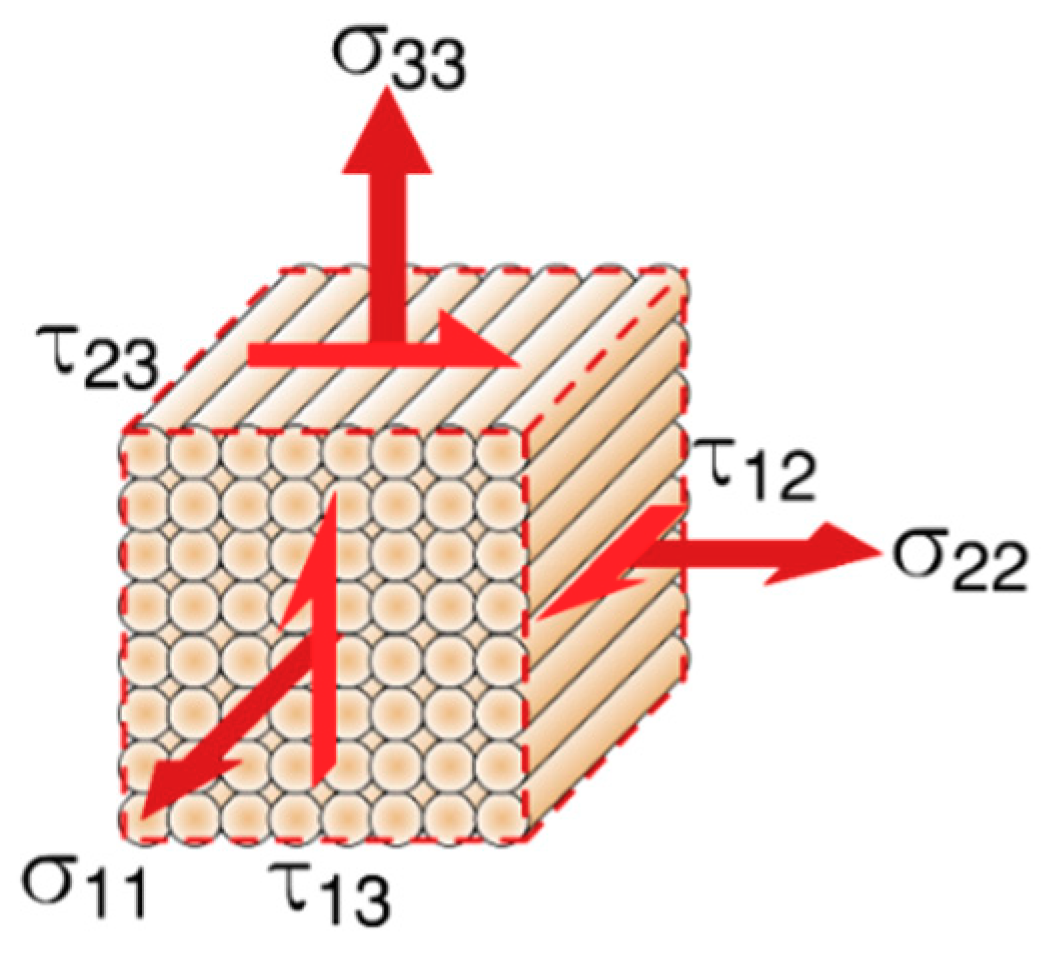
The notation
and
indicates axial and shear stresses respectively, as denoted in
Figure 1, showing an element representation of an anisotropic part.
In the original Gol’denblat-Kopnov model, the components
and
in Equation (2) were assumed to be zero to simplify calculations [
7], essentially eliminating the possibility of capturing any interactions between axial loads and shear stresses. The criterion proposed by Osswald and Osswald in 2017 overcomes these limitations by calculating interaction effects through the use of the derivative of the failure surface within a particular stress plane, thus requiring knowledge of the slope of the envelope in strategic locations [
4]. This additional parameter can easily be computed at any point where the engineering strength is known, by simply performing a series of combined loading mechanical tests in its immediate vicinity. These interaction slopes are denoted
, if it originates in an axial stress plane, or
, if it stems from a shear-axial system. The subscript
represents one of four possible locations where the interaction slope can be obtained in a
stress plane.
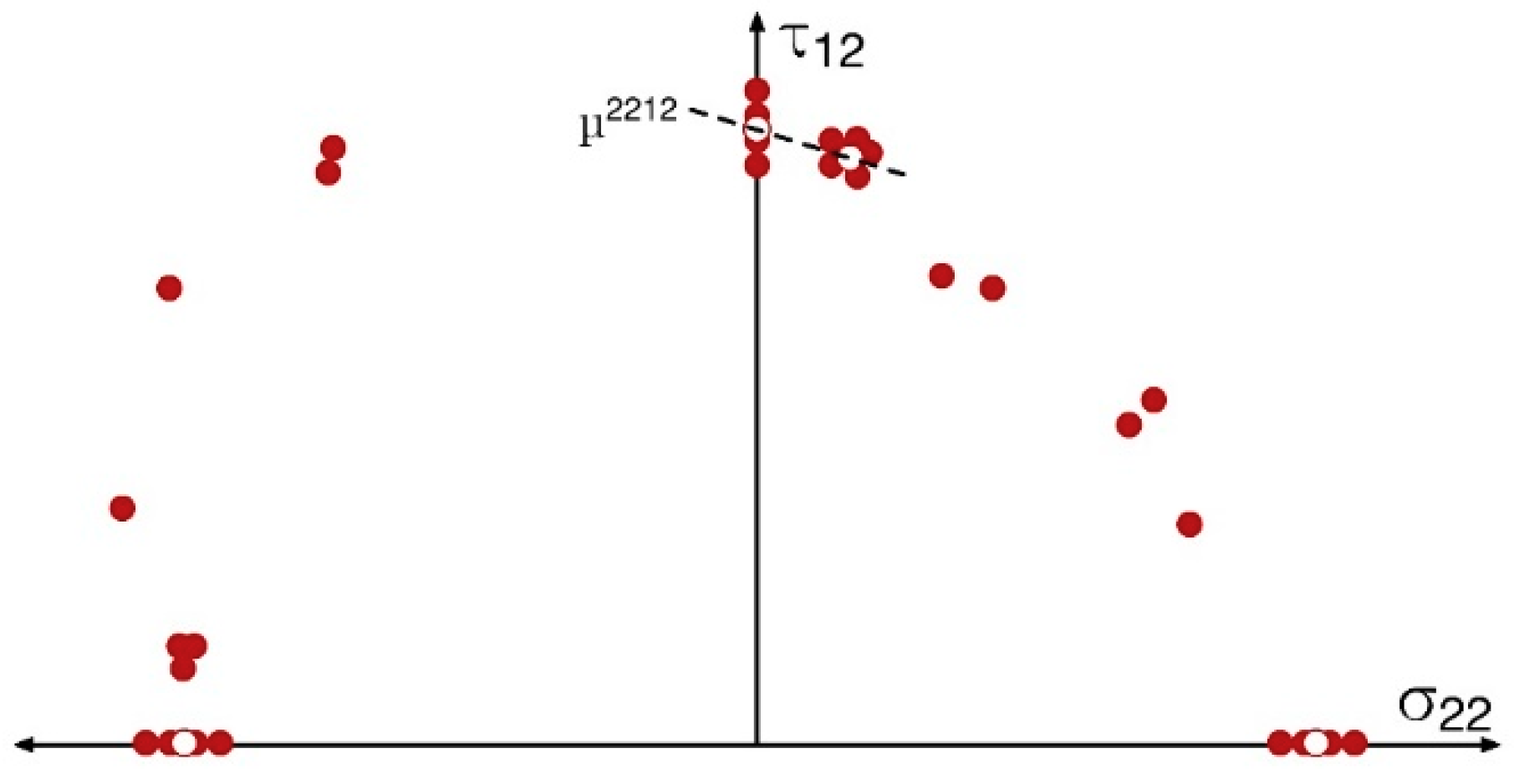
Figure 2 shows a schematic of how one could obtain the interaction slope
from combined loading mechanical tests and pure shear data in the
plane as an example.
Table 1 shows the general formula for each interaction component calculation based on interaction slopes, as derived by Osswald and Osswald [
4]. The term
indicates ultimate shear strength in a shear plane.
Thus, following the nomenclature and procedure described by Gol’denblat and Kopnov [
7], and Osswald and Osswald [
4], one can obtain all of the tensorial components described in Equation (3). The nomenclature used for each parameter is shown in
Table 2. The
parameters represent the shear strength of a torsion specimen produced with beads oriented in a 45° angle, used to measure the
interaction, as indicated by Gol’denblat–Kopnov [
7]. All of the required tensorial component calculations are shown in
Table 3.
Previous work performed by the authors [
2] successfully implemented this criterion to develop a 3D failure envelope for FFF parts produced with a customized acrylonitrile butadiene styrene (ABS) filament, extruded in-house to minimize the impact of the material on the final results. This custom material allowed for tight dimensional control of the filament diameter, full knowledge of the parent material (SABIC MG94 Cycolac ABS), as well as its processing conditions. This information is usually unavailable or not guaranteed when using commercially available filament.
Table 4 shows the resulting tensorial components of the failure function.
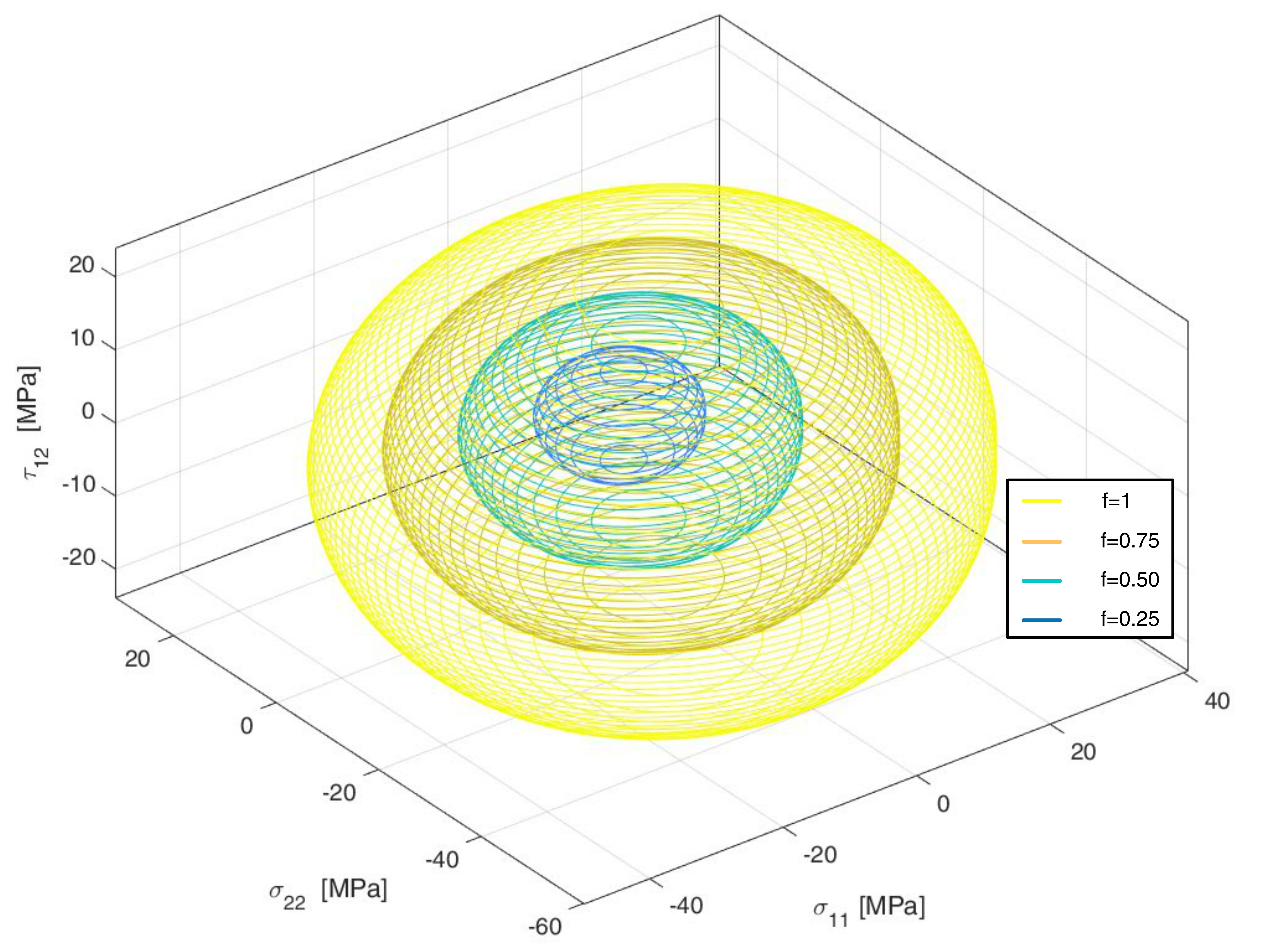
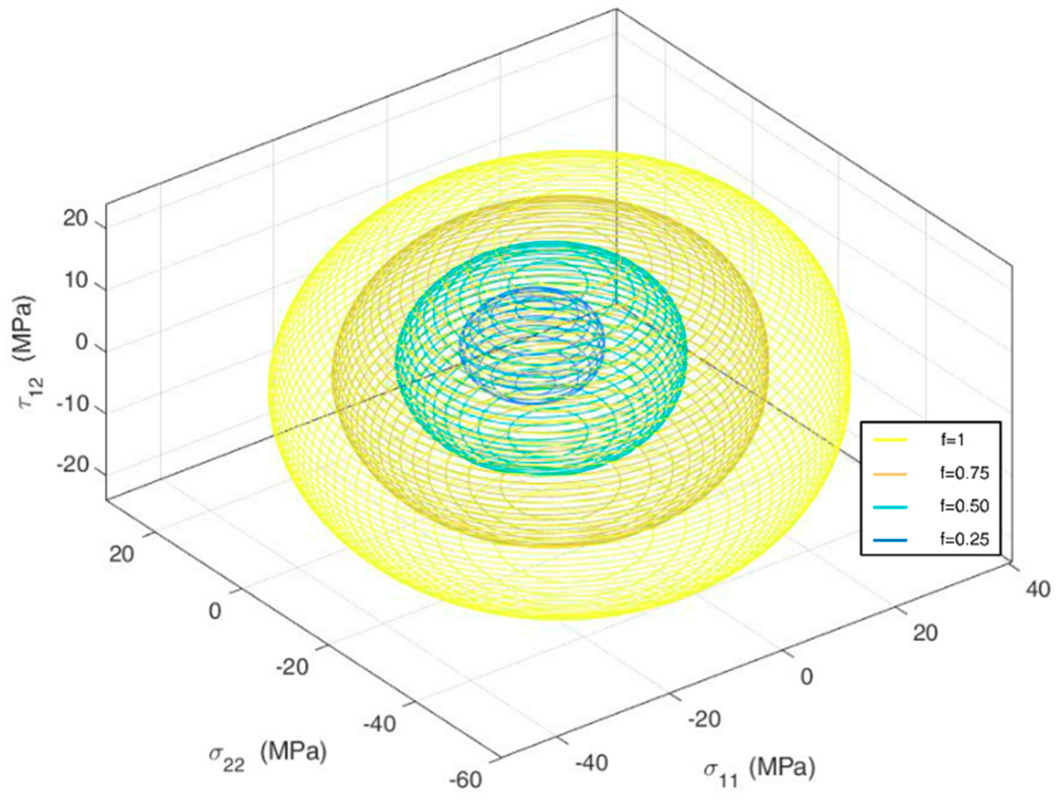
Figure 3 shows the resulting failure envelope, with calculated
values of 1, 0.75, 0.50 and 0.25 to illustrate safety factors of 1, 4/3, 2 and 4 respectively. The resulting surface indicates considerable interaction effects between axial directions, as well as small interactions between shear and axial stresses [
2].
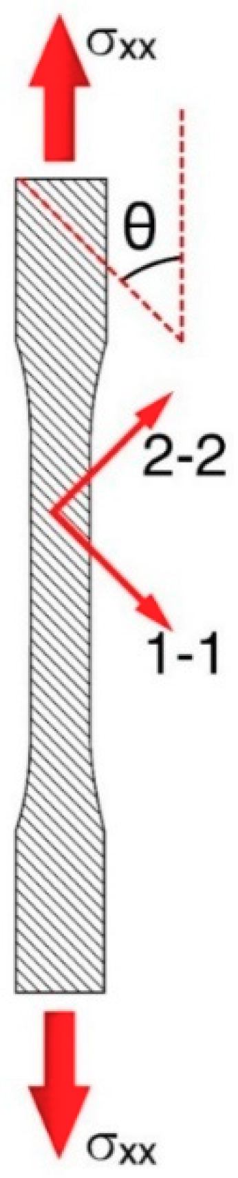
In order to experimentally validate the results of the failure surface, combined loads can be generated in the principal directions and compared to the envelope. According to laminate theory, one can generate a biaxial stress state along the principal material axes by applying off-axis uniaxial stress [
8], as shown in
Figure 4.
Using this type of loading condition, the results can be converted to the principal coordinate system by using the following transformation [
8]:
This study proposes verification of the previously developed envelope through this type of uniaxial tensile test. Multiple FFF coupons produced with a variety of raster angles and are used to compare the resulting complex stress states in the local coordinate system of the part to the failure line determined through application of the failure criterion.
2. Experimental Methods
The toolpath of the tensile coupons was generated using the SciSlice engine [
9], following the ASTM D-638 Type I standard geometry [
10] due to a lack of a standardized test for AM parts. The outlines of the coupons were printed in the x-y plane, with each stacked layer building up to the desired thickness of 3.2 mm. In order to test a variety of combined loading scenarios, six raster configurations were selected: 0°, 30°, 45°, 60°, 75°, and 90° with respect to the loading direction, as depicted in
Figure 4. The designed toolpath allowed for uninterrupted bead deposition on each layer, starting on one corner of the specimens. Each orientation was replicated five times. The printing conditions were exactly the same as those used by the authors to generate the original failure envelope. These are shown in
Table 5. Specimen were printed in a traditional desktop 3D printer (Lulzbot TAZ5, Aleph Objects, Loveland, CO, USA), using a customized 2.85 mm ABS filament extruded in-house, based on the Cycolac MG94 material produced by SABIC.
Mechanical tests were conducted on an Instron 5967 dual column universal testing machine with a 30 kN load cell, using the recommended testing speed of 5 mm/min, dictated by the ASTM standard [
10]. All of the data acquisition was handled through the accompanying Instron Bluehill 3 software.
The resulting experimental data was compared to the original failure envelope developed by the authors in previous work. To better visualize the results, the original mathematical formula, expressed in terms of stresses in the local coordinate system of the polymer beads, was translated into the global coordinate system. The transformation involves using the relation shown in Equation (3), resulting in the following system of equations:
Solving for allows the failure surface to be expressed as a function of the raster angle and the tensorial components.
3. Results
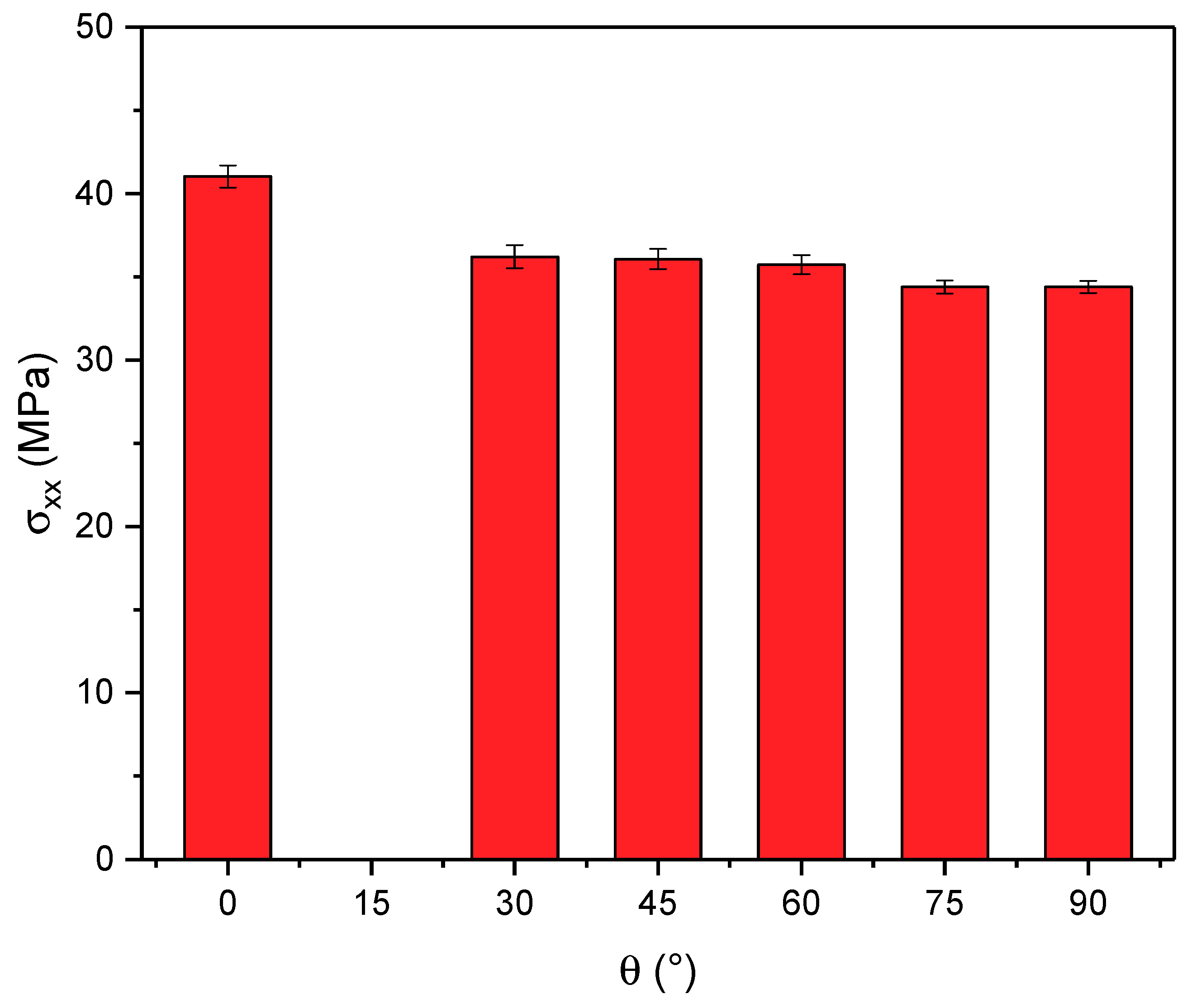
The maximum stress registered during testing gradually decreased as a function of the angle of the beads, with the highest value belonging to the coupons with a raster orientation parallel to the load direction, and the lowest being the specimens with the beads oriented perpendicular to the direction of the tensile stress. This is in accordance with previous work on the subject, investigating the strength of FFF parts as a function of the raster orientation [
3,
11]. The tensile strength in the 0° orientation was approximately 20% higher than that observed for coupons produced with a 90° raster. Results are summarized in
Figure 5. Error bars represent one standard deviation. All specimens showed a certain degree of plastic deformation, with the 0° orientation having the most prominent failure strain and dropping drastically as the angle increased to 90°.
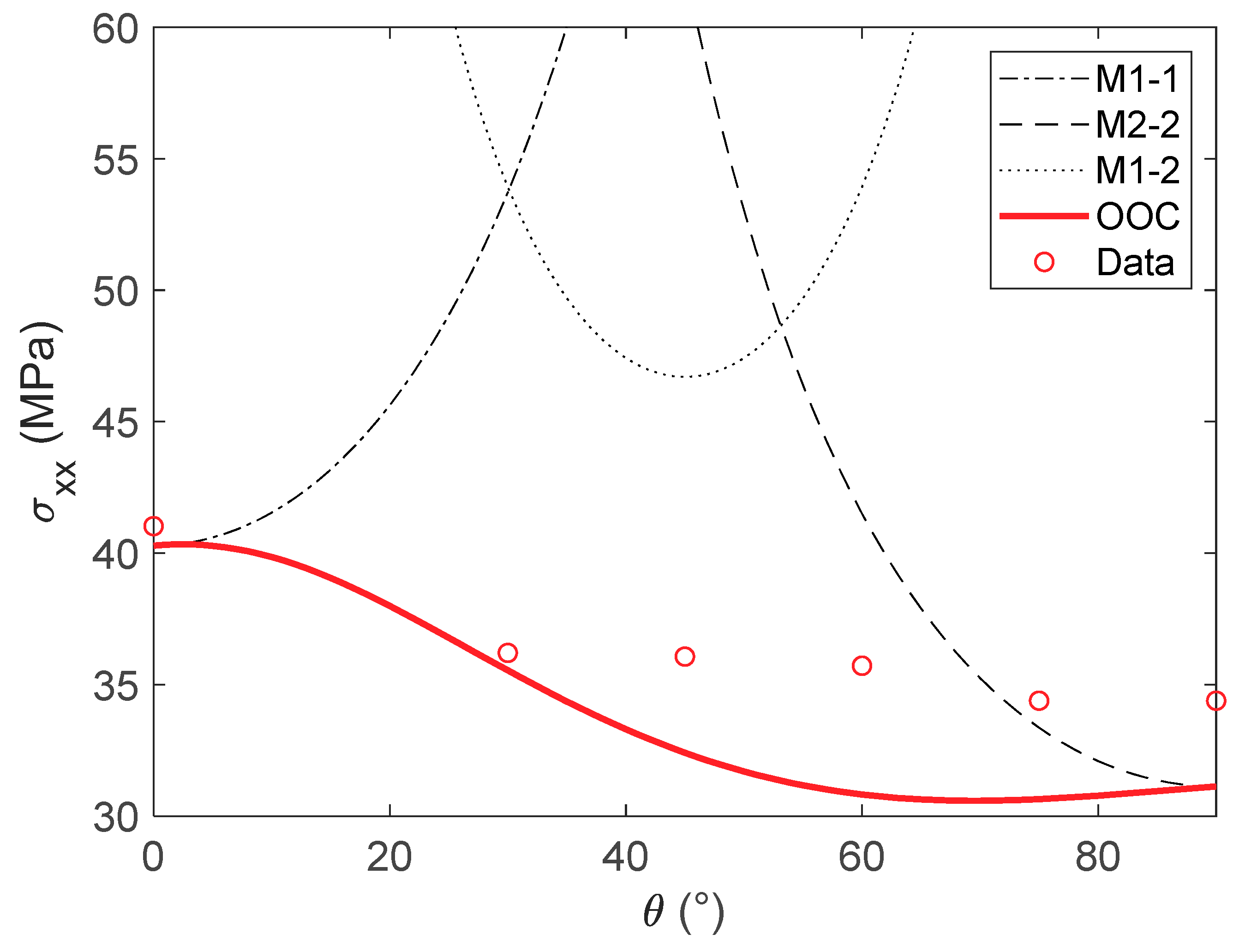
Plotting the failure line determined through the Osswald and Osswald criterion (OOC) delimits a safe-unsafe threshold: any stress state above the line will likely result in part failure. For additional comparison, lines determined using the maximum stress criterion are shown, using the
and
values determined for the OOC. These are labeled M1-1, M2-2 and M1-2 respectively. Finally, overlaying the experimental data results in
Figure 6.
It can be seen from the graph that no data point trespasses into the safety zone defined by the OOC. In comparison, simply using the maximum stress criterion proves inadequate, given that all the experimental tests fall well into the safe area determined by this criterion. These results give credence to the previously developed failure envelope, as well as the Osswald and Osswald Failure criterion.


