A Numerical Study on High Velocity Impact Behavior of Titanium Based Fiber Metal Laminates


Abstract
1. Introduction
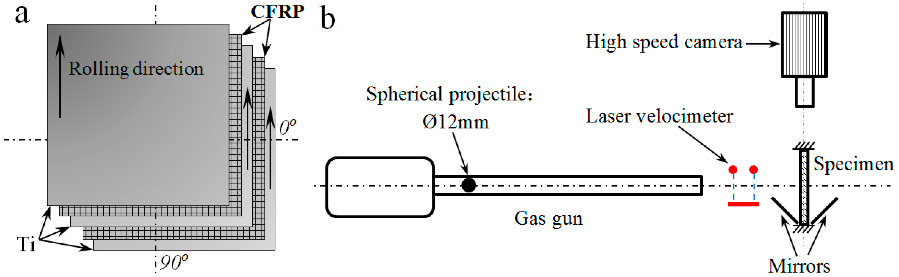
2. Materials
3. Overview of the Experimental Study
4. Numerical Simulation
4.1. Constitutive Material Model
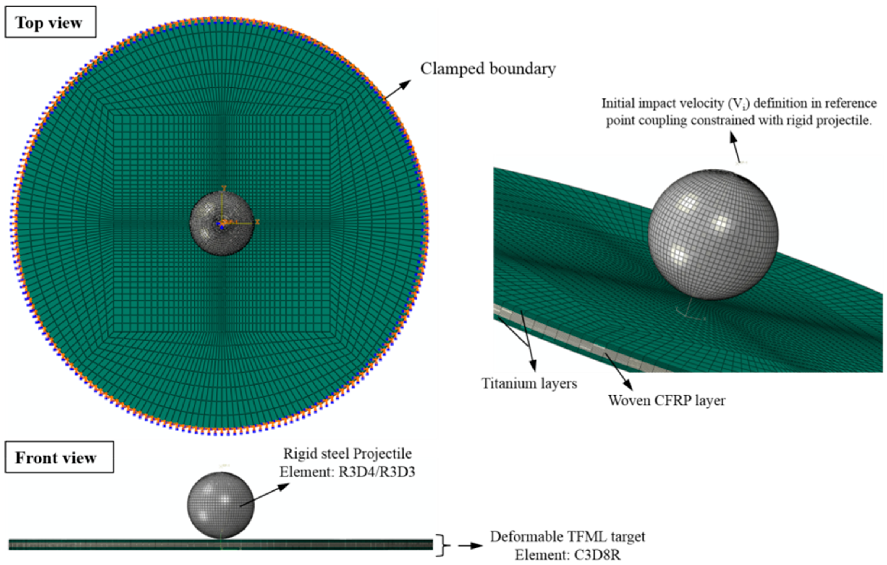
4.2. Initial and Boundary Conditions
4.3. Element and Mesh Details
5. Results and Discussion
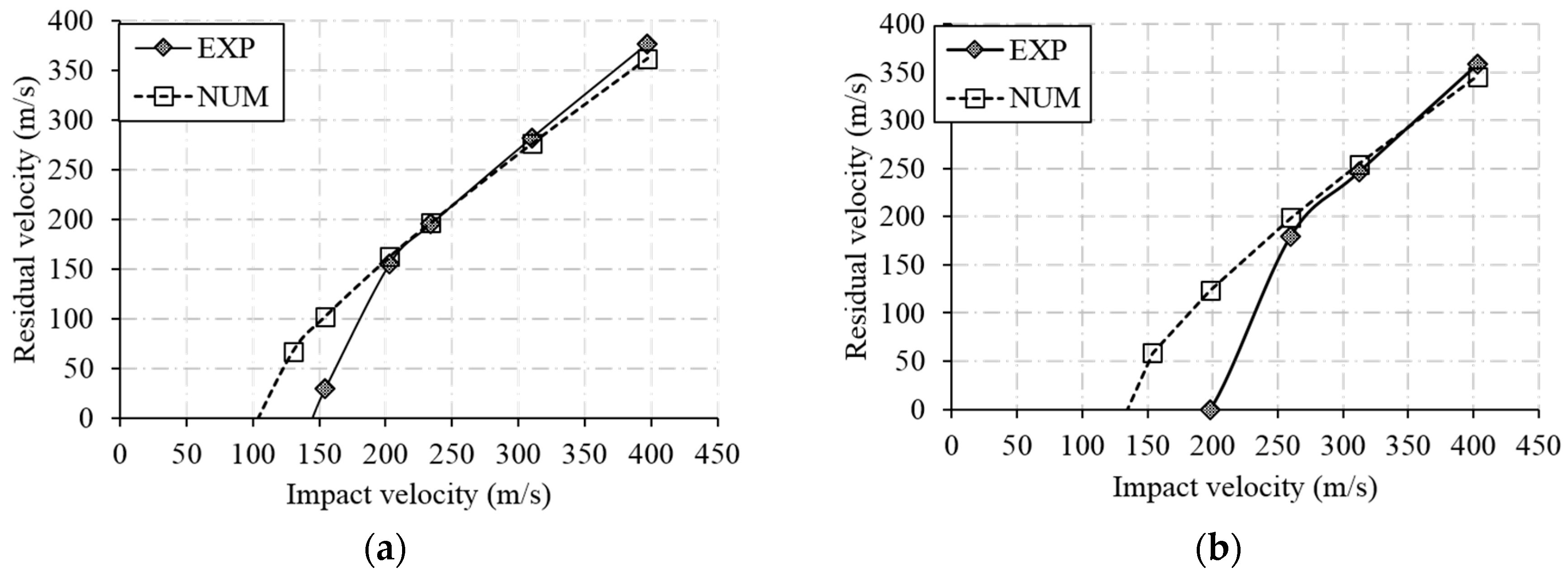
5.1. Projectile Velocity (Vp)
- Rebound velocity (Vrb): For impact velocity smaller than the ballistic velocity (Vi < Vb), the incident kinetic energy () of the projectile is not enough to perforate the target and the projectile rebound back after it transforms all of its energy to the target. In this case, the velocity of the projectile (Vp) monotonically decreases to the rebound velocity by passing through zero (Vrb < 0) at which the projectile regains kinetic energy through the elastic rebound of the target and bounces back in the opposite direction.
- Ballistic velocity (Vb): At impact velocity equals the ballistic velocity (Vi = Vb), the kinetic energy of the projectile () is just enough to completely perforate the target and the velocity of the projectile becomes zero (Vp = 0) at the end of the contact event.
- Residual velocity (Vr): For impact velocity larger than the ballistic velocity (Vi > Vb), only a small fraction of the kinetic energy of the projectile () is enough to perforate the target and the projectile continues its travel through the target just like a rigid body at a constant residual velocity (Vp = Vr).
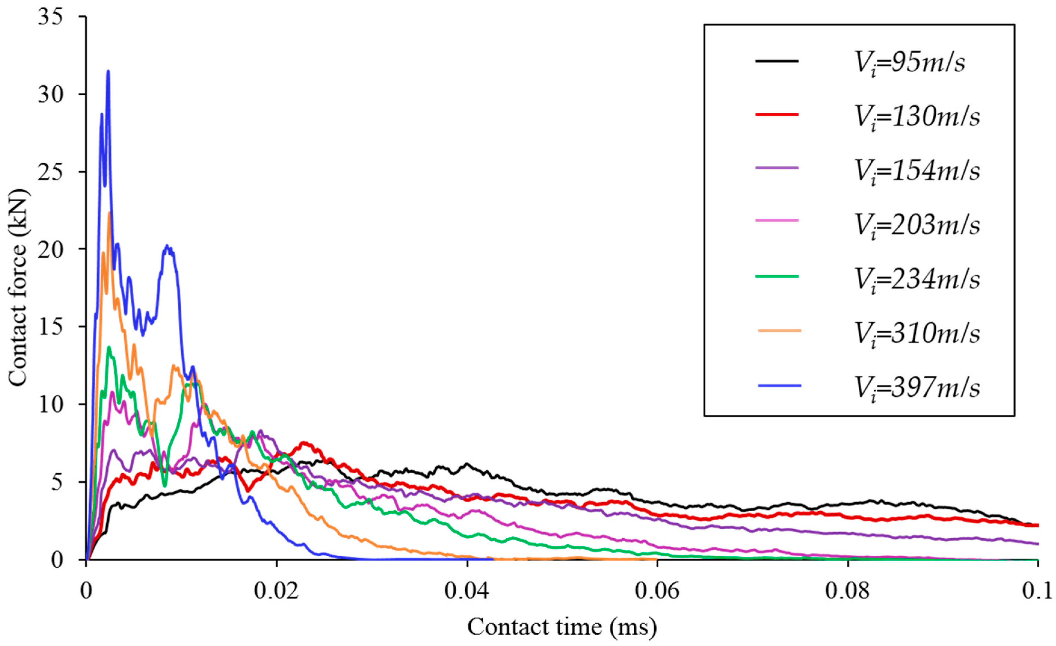
5.2. Contact History
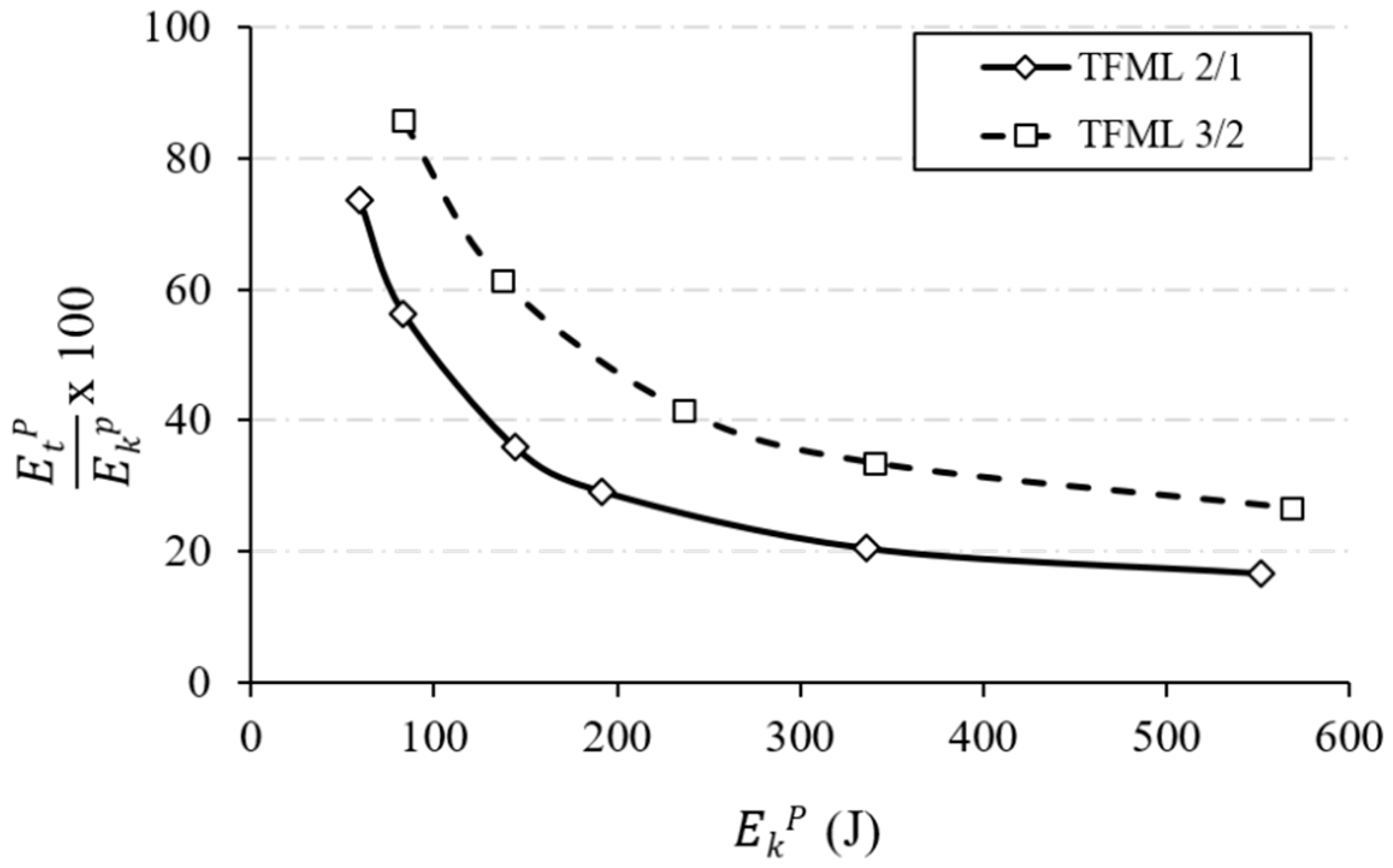
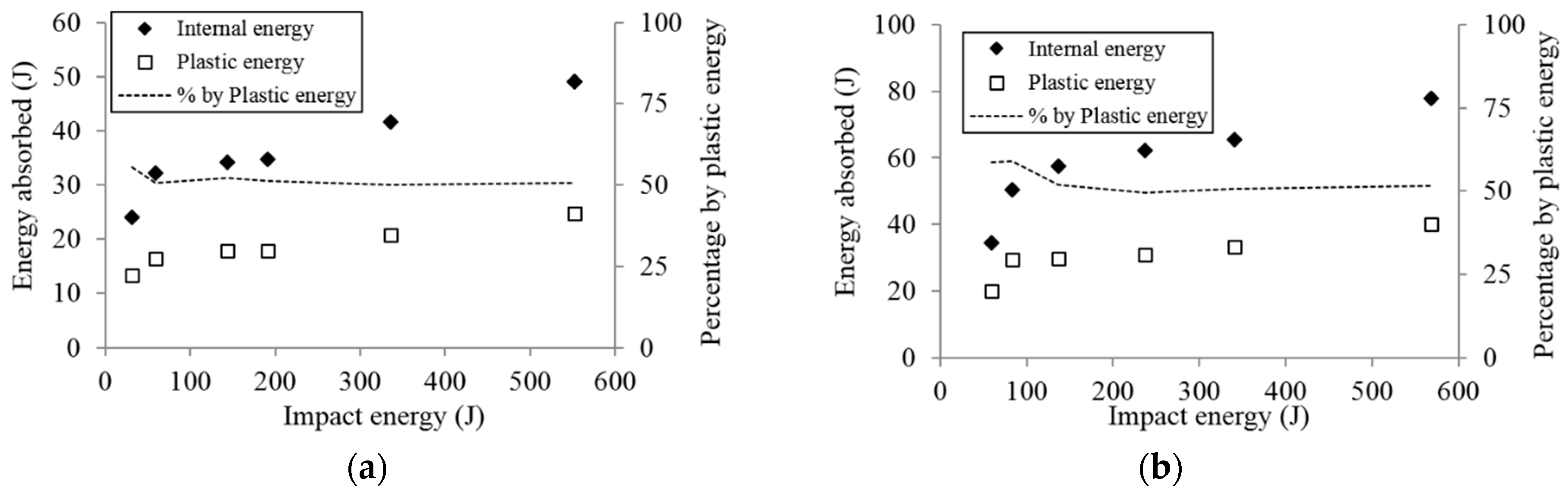
5.3. Energy Dissipation
- Undergo global and local plastic deformation.
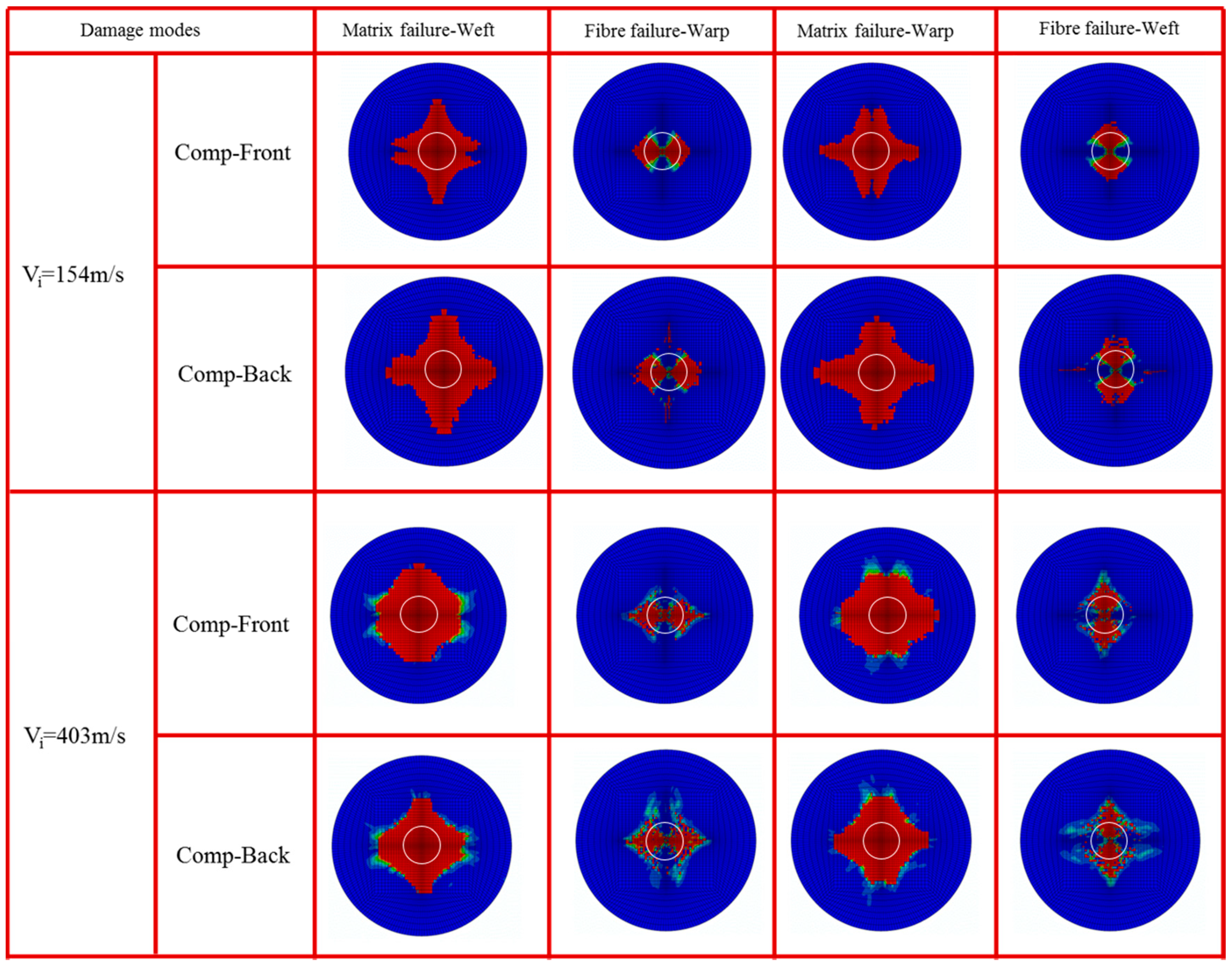
- Creating different fibre/matrix failure modes of composite layers.
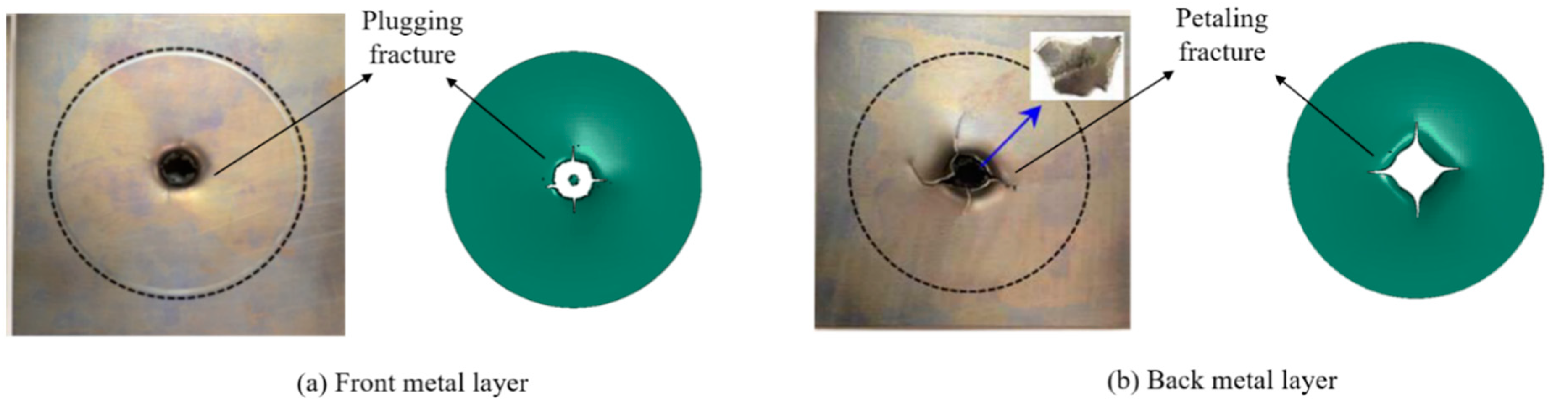
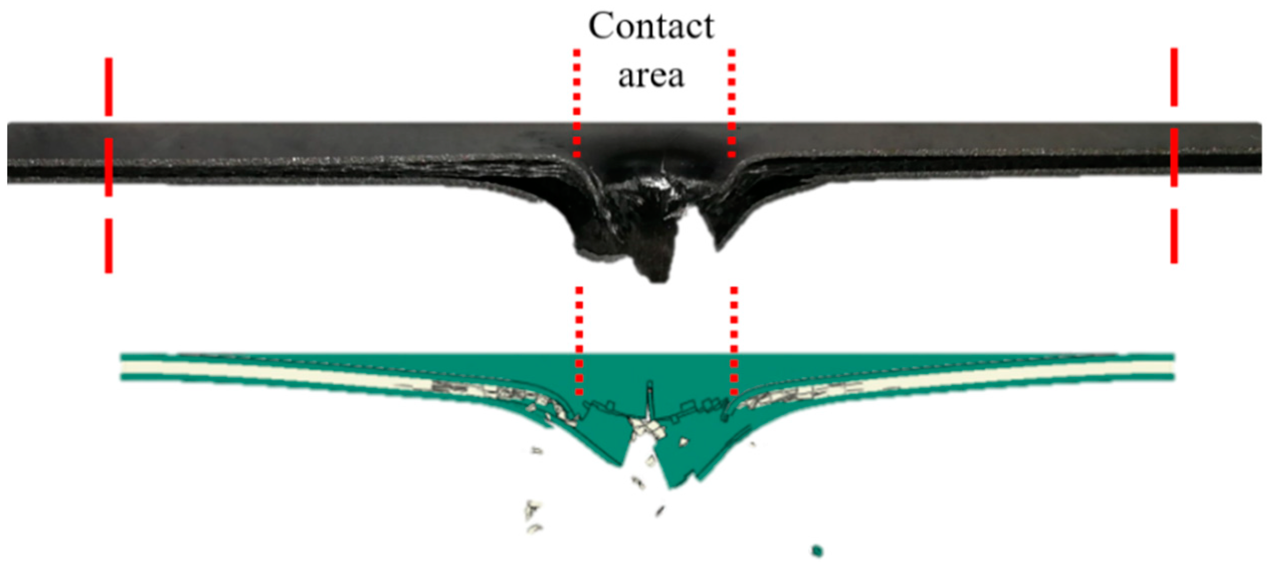
- Forming petaling fracture and bending of petals on the bottom metal surface.
- Shear plugging on top of the impacted metal surface.
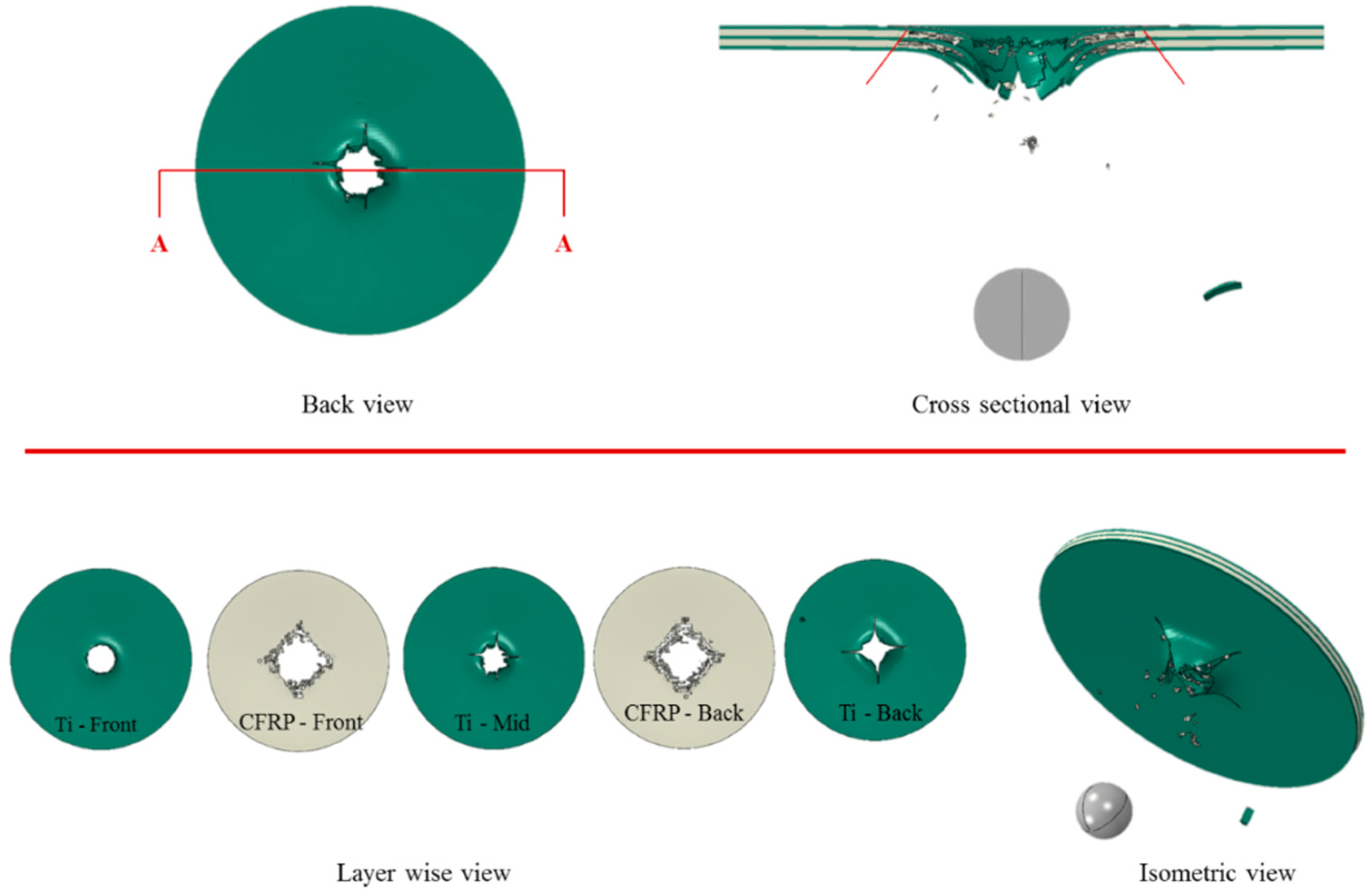
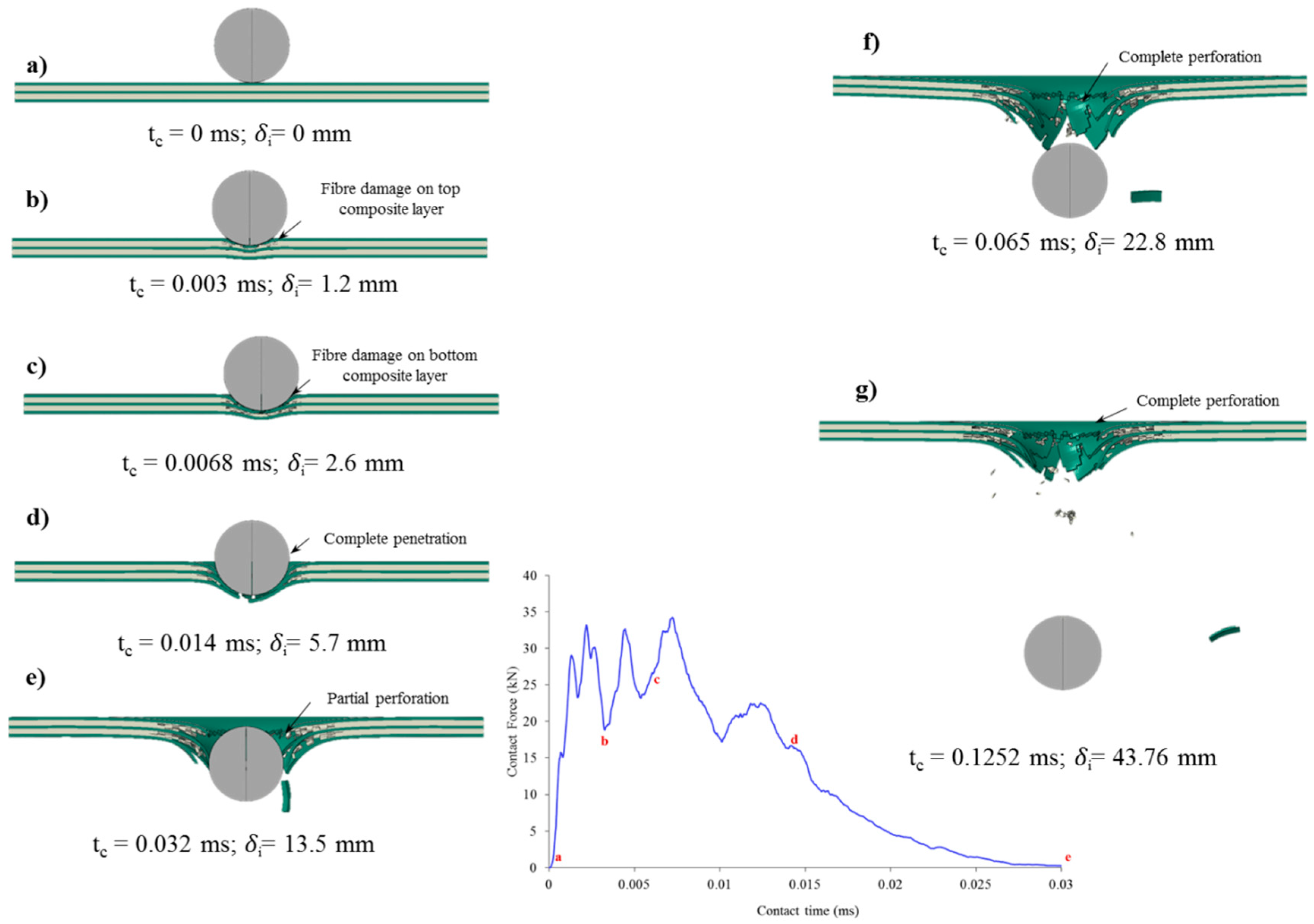
5.4. Damage Morphology
- Compressive contact pressure due to the projectile impact causes localized dent deformation under the contact area. (Figure 9b)
- Damage occurs in CFRP composite layers caused by matrix cracking and fibre fracture failure modes. The damage originates first in the top CFRP layer and then spreads to the bottom layer at higher displacement of the projectile. (Figure 9b,c)
- Fracture in the titanium layer occurs first at the bottom side and soon after the other metal layers are instantaneously fractured. The state of damage at this stage is termed as “complete penetration” denoting that damage occurs to all layers in the TFML panel. (Figure 9d)
- The projectile perforated through damaged layers of the laminate postulated here as “partial perforation” where the projectile does not eject and still holds contact with the completely penetrated target. (Figure 9e)
- Finally, the “complete perforation” stage is reached, where the projectile completely lost its contact with the target and continues at constant residual velocity (Vr). At this point, the contact force that is resisted by the target reads zero. (Figure 9f)
6. Concluding Remarks
- Adding an additional layer of Titanium and a CFRP layer to create TFML-3/2 from 2/1 increases the weight of the target by 58%. The larger thickness of TFML-3/2 increased the ballistic limit velocity by 32% (by experiment) and 37% (by numerical) compared to TFML-2/1.
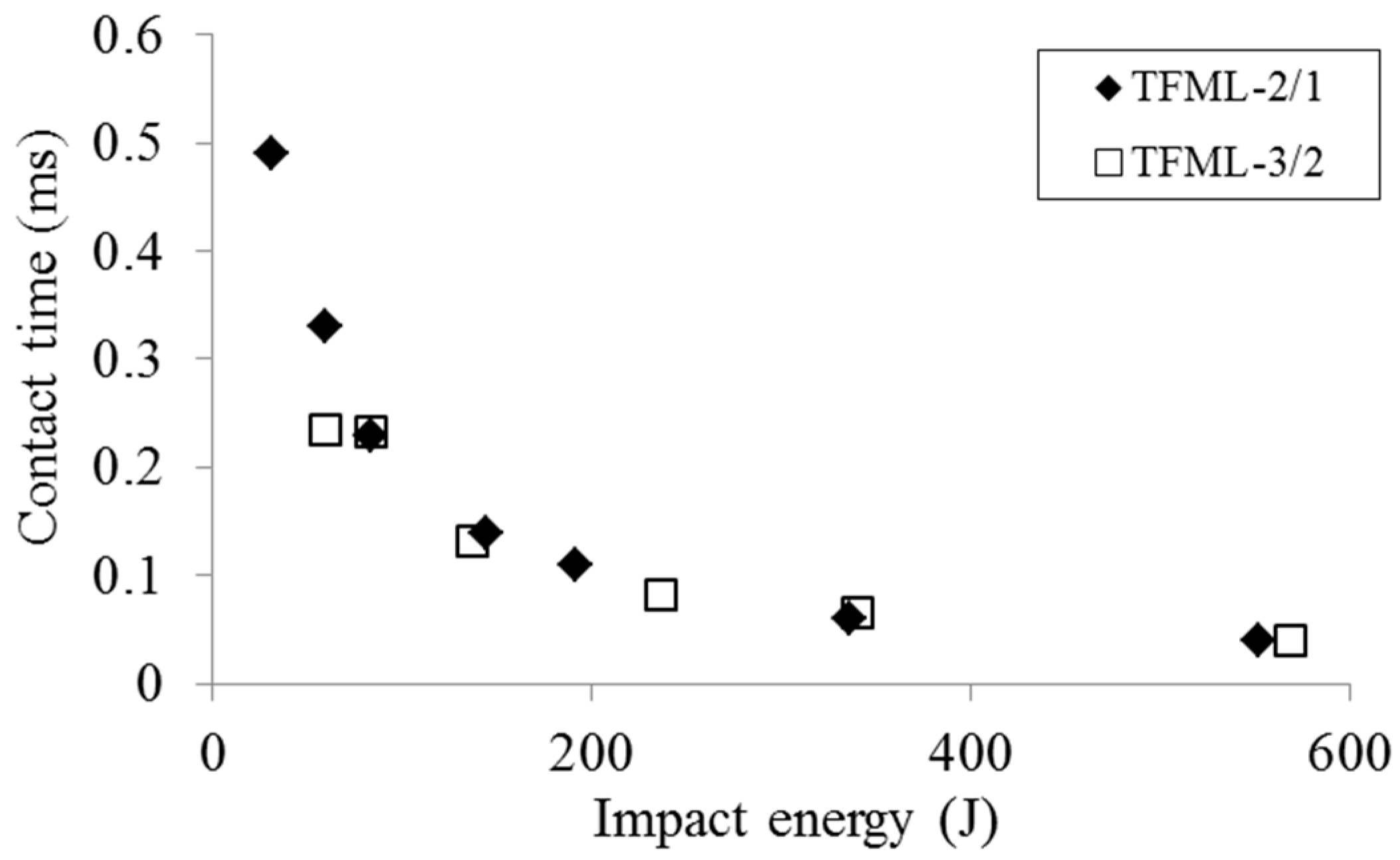
- The perforation resistance of the TFML panels were dictated by change in the projectile kinetic energy , and the total contact time shows exponential decay with increases in impact energy.
- The plot of contact history shows that the peak contact load increases with increases in impact velocity, even after the ballistic limit state.
- Having similar metal volume fraction (MVF), the percentage of energy that was absorbed by plastic deformation of the Titanium layers was found to be constant (approximately 50%) for the TFML 2/1 and 3/2 panels, even though their geometric thickness was different.
- At all of the impact velocity range, the damage area in the perforated TFML panels was always larger than the maximum projectile contact area, both in layer wise and at the laminate level. The top metal layer showed a plugging type of failure while the bottom metal layer formed a petaling kind of failure with a visible dome shaped damage surface. Fibre and matrix failure modes of the woven composite layers were symmetric in shape because of its balanced material property, whereas the former had peanut and the latter had rhombus shaped damage surfaces.
Author Contributions
Funding
Acknowledgments
Conflicts of Interest
Appendix A. Material Model Used for Metal Layer
Appendix B. Material Model Used for Plain Weave Composite Layer
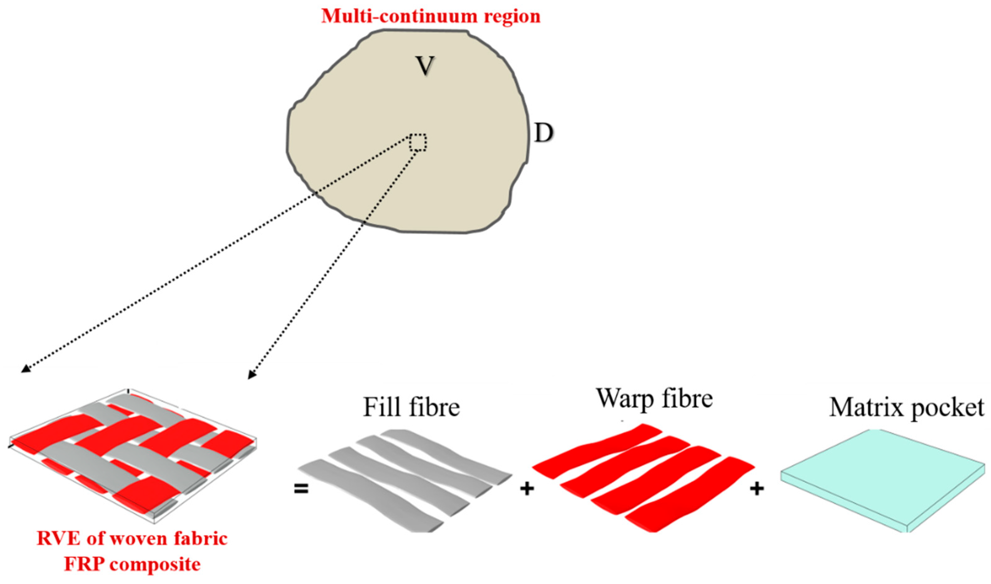
Appendix B.1. Overview of Multi-Continuum Theory (MCT)

Appendix B.2. MCT Failure Criteria
Appendix B.2.1. Matrix Failure Criteria
Appendix B.2.2. Fibre Failure Criterion
References
- Navarro, C.; Martinez, M.A.; Cortés, R.; Sánchez-Gálvez, V. Some observations on the normal impact on ceramic faced armours backed by composite plates. Int. J. Impact Eng. 1993, 13, 145–156. [Google Scholar] [CrossRef]
- Van der Werff, H.; Heisserer, U. 3—High-performance ballistic fibers: Ultra-high molecular weight polyethylene (UHMWPE). In Advanced Fibrous Composite Materials for Ballistic Protection; Woodhead Publishing: Cambridge, UK, 2016; pp. 71–107. [Google Scholar]
- Vlot, A.; Gunnink, J.W. Fibre Metal Laminates: An Introduction; Kluwer Academic Publishers: Berlin/Heidelberg, Germany, 2001. [Google Scholar]
- Vlot, A. Impact loading on fibre metal laminates. Int. J. Impact Eng. 1996, 18, 291–307. [Google Scholar] [CrossRef]
- Morinière, F.D.; Alderliesten, R.C.; Benedictus, R. Modelling of impact damage and dynamics in fibre-metal laminates—A review. Int. J. Impact Eng. 2014, 67, 27–38. [Google Scholar] [CrossRef]
- Hoo Fatt, M.S.; Lin, C.; Duane, M.R.; Dale Hopkins, A. Ballistic impact of GLARE™ fiber–metal laminates. Compos. Struct. 2003, 61, 73–88. [Google Scholar] [CrossRef]
- Compston, P.; Cantwell, W.J.; Jones, C.; Jones, N. Impact perforation resistance and fracture mechanisms of a thermoplastic based fiber-metal laminate. J. Mater. Sci. Lett. 2001, 20, 597–599. [Google Scholar] [CrossRef]
- Langdon, G.S.; Cantwell, W.J.; Nurick, G.N. The blast response of novel thermoplastic-based fibre-metal laminates—Some preliminary results and observations. Compos. Sci. Technol. 2005, 65, 861–872. [Google Scholar] [CrossRef]
- Vo, T.P.; Guan, Z.W.; Cantwell, W.J.; Schleyer, G.K. Low-impulse blast behaviour of fibre-metal laminates. Compos. Struct. 2012, 94, 954–965. [Google Scholar] [CrossRef]
- Vo, T.P.; Guan, Z.W.; Cantwell, W.J.; Schleyer, G.K. Modelling of the low-impulse blast behaviour of fibre–metal laminates based on different aluminium alloys. Compos. Part B Eng. 2013, 44, 141–151. [Google Scholar] [CrossRef]
- Cortés, P.; Cantwell, W.J. Interfacial fracture properties of carbon fiber reinforced PEEK/titanium fiber-metal laminates. J. Mater. Sci. Lett. 2002, 21, 1819–1823. [Google Scholar] [CrossRef]
- Cortés, P.; Cantwell, W.J. The impact properties of high-temperature fiber-metal laminates. J. Compos. Mater. 2007, 41, 613–632. [Google Scholar] [CrossRef]
- Boyer, R.R. Attributes, characteristics, and applications of titanium and its alloys. JOM 2010, 62, 21–24. [Google Scholar] [CrossRef]
- Li, X.; Zhang, X.; Guo, Y.; Shim, V.P.W.; Yang, J.; Chai, G.B. Influence of fiber type on the impact response of titanium-based fiber-metal laminates. Int. J. Impact Eng. 2018, 114, 32–42. [Google Scholar] [CrossRef]
- Yen, C.F. A ballistic material model for continuous-fiber reinforced composites. Int. J. Impact Eng. 2012, 46, 11–22. [Google Scholar] [CrossRef]
- Silva, M.A.G.; Cismaşiu, C.; Chiorean, C.G. Numerical simulation of ballistic impact on composite laminates. Int. J. Impact Eng. 2005, 31, 289–306. [Google Scholar] [CrossRef]
- Iqbal, M.A.; Tiwari, G.; Gupta, P.K.; Bhargava, P. Ballistic performance and energy absorption characteristics of thin aluminium plates. Int. J. Impact Eng. 2015, 77, 1–15. [Google Scholar] [CrossRef]
- ABAQUS Technical Brief. Simulation of the Ballistic Perforation of Aluminum Plates with Abaqus/Explicit. Available online: https://www.3ds.com/fileadmin/PRODUCTS-SERVICES/SIMULIA/RESOURCES/aero-ballistic-perforation-alumnium-plates-12.pdf (accessed on 18 October 2018).
- ABAQUS Technical Brief. Projectile Impact on a Carbon Fiber Reinforced Plate. Available online: https://www.3ds.com/fileadmin/PRODUCTS-SERVICES/SIMULIA/RESOURCES/Aero-Projectile-Impact-on-a-Carbon-Fiber-Reinforced-06.pdf (accessed on 18 October 2018).
- Pach, J.; Pyka, D.; Jamroziak, K.; Mayer, P. The experimental and numerical analysis of the ballistic resistance of polymer composites. Compos. Part B Eng. 2017, 113, 24–30. [Google Scholar] [CrossRef]
- Reinhart, W.D.; Chhabildas, L.C.; Carroll, D.E.; Thornhill, T.G.; Winfree, N.A. Equation of State Measurements of Materials Using a Three-Stage Gun to Impact Velocities of 11 km/s. In Proceedings of the 7th Hypervelocity Impact Symposium (HIVS), Galveston, TX, USA, 6–10 November 2000. [Google Scholar]
- Liaw, B.; Yaghoubi, A.S. Effect of lay-up orientation on ballistic impact behaviors of GLARE 5 FML beams. Int. J. Impact Eng. 2013, 54, 138–148. [Google Scholar]
- Liaw, B.; Yaghoubi, A.S. Thickness influence on ballistic impact behaviors of GLARE 5 fiber-metal laminated beams: Experimental and numerical studies. Compos. Struct. 2012, 94, 2585–2598. [Google Scholar]
- Soutis, C.; Mohamed, G.; Hodzic, A. Modelling the structural response of GLARE panels to blast load. Compos. Struct. 2011, 94, 267–276. [Google Scholar] [CrossRef]
- Sitnikova, E.; Guan, Z.W.; Schleyer, G.K.; Cantwell, W.J. Modelling of perforation failure in fibre metal laminates subjected to high impulsive blast loading. Int. J. Solids Struct. 2014, 51, 3135–3146. [Google Scholar] [CrossRef]
- Key, C.T.; Six, R.W.; Hansen, A.C. A three-constituent multicontinuum theory for woven fabric composite materials. Compos. Sci. Technol. 2003, 63, 1857–1864. [Google Scholar] [CrossRef]
- Key, C.T.; Schumacher, S.C.; Hansen, A.C. Progressive failure modeling of woven fabric composite materials using multicontinuum theory. Compos. Part B Eng. 2007, 38, 247–257. [Google Scholar] [CrossRef]
- Kotzakolios, T.; Vlachos, D.E.; Kostopoulos, V. Blast response of metal composite laminate fuselage structures using finite element modelling. Compos. Struct. 2011, 93, 665–681. [Google Scholar] [CrossRef]
- Nakatani, H.; Kosaka, T.; Osaka, K.; Sawada, Y. Damage characterization of titanium/GFRP hybrid laminates subjected to low-velocity impact. Compos. Part A Appl. Sci. Manuf. 2011, 42, 772–781. [Google Scholar] [CrossRef]
- Kay, G. Failure Modeling of Titanium 6Al-4V and Aluminum 2024-T3 with the Johnson-Cook Material Model; DOT/FAA/AR-03/57; U.S. Department of Transportation: Washington, DC, USA, 2003.
- Theory Manual: Autodesk simulation composite analysis 2015. Available online: http://help.autodesk.com/view/ACMPAN/2015/ENU/ (accessed on 22 October 2018).
- Kerley, G.I. Equations of State for Titanium and Ti6A14V Alloy; SANDIA Report 3785; Sandia National Laboratories: Albuquerque, NM, USA, 2003.
- Tennyson, R.C.; Wharram, G.E. Evaluation of Failure Criterion for Graphite/Epoxy Fabric Laminates; NASA Contract Report—172547. Available online: https://ntrs.nasa.gov/archive/nasa/casi.ntrs.nasa.gov/19850010715.pdf (accessed on 18 October 2018).
- Kaboglu, C.; Mohagheghian, I.; Zhou, J.; Guan, Z.; Cantwell, W.J.; John, S.; Blackman, B.R.K.; Kinloch, A.J.; Dear, J.P. High-velocity impact deformation and perforation of fibre metal laminates. J. Mater. Sci. 2018, 53, 4209–4228. [Google Scholar] [CrossRef]
- Seo, H.; Hundley, J.; Hahn, H.T.; Yang, J.M. Numerical Simulation of Glass-Fiber-Reinforced Aluminum Laminates with Diverse Impact Damage. AIAA J. 2010, 48, 676–687. [Google Scholar] [CrossRef]
- Recht, R.F.; Ipson, T.W. Ballistic Perforation Dynamics. J. Appl. Mech. 1963, 30, 384–390. [Google Scholar] [CrossRef]
- Xie, W.; Zhang, W.; Kuang, N.; Li, D.; Huang, W.; Gao, Y.; Ren, P. Experimental investigation of normal and oblique impacts on CFRPs by high velocity steel sphere. Compos. Part B Eng. 2016, 99, 483–493. [Google Scholar] [CrossRef]
- Lin, C.; Hoo Fatt, M.S. Perforation of Composite Plates and Sandwich Panels under Quasi-static and Projectile Loading. J. Compos. Mater. 2006, 40, 1801–1840. [Google Scholar] [CrossRef]
- Corbett, G.G.; Reid, S.R.; Johnson, W. Impact loading of plates and shells by free-flying projectiles: A review. Int. J. Impact Eng. 1996, 18, 141–230. [Google Scholar] [CrossRef]
- Abrate, S. Impact on Composite Structures; Cambridge University Press: Cambridge, UK, 1998. [Google Scholar]
- Steven Mayes, A.; Hansen, C.J. Multicontinuum Failure Analysis of Composite Structural Laminates. Mech. Compos. Mater. Struct. 2001, 8, 249–262. [Google Scholar] [CrossRef]


| Nomenclature | Stacking Sequence | Thickness (mm) | Areal Density (g/cm2) | MVF | |||
|---|---|---|---|---|---|---|---|
| Ti | CF | TFML | EXP | NUM | |||
| TFML 2/1 | Ti/CF/Ti | 1 | 0.85 | 1.85 | 0.565 | 0.572 | 0.54 |
| TFML 3/2 | Ti/CF/Ti/CF/Ti | 1.5 | 1.7 | 3.2 | 0.899 | 0.914 | 0.47 |
| Input Parameters for the Mie-Gruneisen Equation of State (EOS) Model [32] | |||||||||||
| Reference Density (kg/m3) | Gruneisen Coeffiecient (Γ0) | Parameters (co) | Parameter (s) | Reference Temperature (K) | Specific Heat (J/kg K) | ||||||
| 4418 | 1.25 | 4973 | 1.111 | 293.2 | 670 | ||||||
| Input Parameters for the Johnson-Cook Plasticity Model [30] | |||||||||||
| A (MPa) | B (MPa) | N | θmelt (K) | θtransition (K) | m | C | ε0 (1/s) | ||||
| 1000 | 331 | 0.34 | 1903.15 | 293.2 | 0.8 | 0.012 | 1 | ||||
| Input Parameters for the Johnson-Cook Dynamic Failure Model [30] | |||||||||||
| d1 | d2 | d3 | d4 | d5 | |||||||
| −0.09 | 0.25 | 0.5 | 0.014 | 3.87 | |||||||
| Young’s modulus (GPa) | |||
| *E11 = 69.3 | E22 = E11 = 69.3 | E33 = 8.79 | |
| Poisson’s ratio | |||
| ν12 = 0.07 | ν13 = 0.367 | ν23 = 0.367 | |
| Shear Modulus (GPa) | |||
| * G12 = 4.80 | G13 = 3.04 | G23 = 3.04 | |
| Tensile failure strength (MPa) | |||
| * X1t = 358 | X2t = X1t = 488 | ||
| Compressive failure strength (MPa) | |||
| X1c = 391 | X2c = 460 | ||
| Shear strength (MPa) | |||
| * S12 = 75.4 | S13 = 119 | ||
| Sample | (m/s) | (m/s) | Dimensionless Parameters | ||||
|---|---|---|---|---|---|---|---|
| EXP | NUM | α | β | ||||
| EXP | NUM | EXP | NUM | ||||
| TFML-2/1 | 130 | −36.8 | 66.91 | 1.008 | 0.978 | 2.255 | 1.725 |
| 154 | 29 | 101.8 | |||||
| 203 | 155.6 | 162.6 | |||||
| 234 | 195.5 | 197 | |||||
| 310 | 282.3 | 276.5 | |||||
| 397 | 376.9 | 362.5 | |||||
| TFML-3/2 | 154 | −31.3 | 58.27 | 0.986 | 0.920 | 2.190 | 1.932 |
| 198 | 0 | 123.2 | |||||
| 260 | 180 | 198.9 | |||||
| 312 | 246 | 254.4 | |||||
| 403 | 357.8 | 345.1 | |||||
© 2018 by the authors. Licensee MDPI, Basel, Switzerland. This article is an open access article distributed under the terms and conditions of the Creative Commons Attribution (CC BY) license (http://creativecommons.org/licenses/by/4.0/).
Share and Cite
Chai, G.B.; Manikandan, P.; Li, X. A Numerical Study on High Velocity Impact Behavior of Titanium Based Fiber Metal Laminates. J. Compos. Sci. 2018, 2, 62. https://doi.org/10.3390/jcs2040062
Chai GB, Manikandan P, Li X. A Numerical Study on High Velocity Impact Behavior of Titanium Based Fiber Metal Laminates. Journal of Composites Science. 2018; 2(4):62. https://doi.org/10.3390/jcs2040062
Chicago/Turabian StyleChai, Gin Boay, Periyasamy Manikandan, and Xin Li. 2018. "A Numerical Study on High Velocity Impact Behavior of Titanium Based Fiber Metal Laminates" Journal of Composites Science 2, no. 4: 62. https://doi.org/10.3390/jcs2040062
APA StyleChai, G. B., Manikandan, P., & Li, X. (2018). A Numerical Study on High Velocity Impact Behavior of Titanium Based Fiber Metal Laminates. Journal of Composites Science, 2(4), 62. https://doi.org/10.3390/jcs2040062