Article

Polylactic Acid (PLA)/Cellulose Nanowhiskers (CNWs) Composite Nanofibers: Microstructural and Properties Analysis

1
Non-Equilibrium Metallic Materials Division, Institute of Metal Research (IMR), Chinese Academy of Sciences (CAS), Shenyang 110016, China
2
Shenyang Kejin Special Materials Co., Ltd., Institute of Metal Research (IMR), Chinese Academy of Sciences (CAS), Shenyang 110101, China
3
Department of Mechanical Engineering, School of Civil and Mechanical Engineering, Curtin University, Perth 6845, Australia
4
Titanium Alloys Division, Institute of Metal Research (IMR), Chinese Academy of Sciences (CAS), Shenyang 110016, China
5
Instruments’ Center for Physical Science, University of Science & Technology of China, Hefei 230026, China
6
SMIT Center, School of Mechatronic Engineering and Automation, Shanghai University, Shanghai 200072, China
*
Author to whom correspondence should be addressed.
J. Compos. Sci. 2018, 2(1), 4; https://doi.org/10.3390/jcs2010004
Submission received: 9 January 2018 / Revised: 23 January 2018 / Accepted: 29 January 2018 / Published: 30 January 2018

Abstract

:
Polylactic acid (PLA)/cellulose nanowhiskers (CNWs) composite nanofibers were successfully produced by electrospinning mixed PLA solutions with CNWs. Observation by means of transmission electron microscopy (TEM) confirms the uniform distribution of CNWs within the PLA nanofibers along the direction of the fiber axis. The spectra of composite nanofibers based on Fourier transform infrared spectroscopy (FTIR) reveal characteristic hydroxyl groups as evidenced by absorption peaks of CNWs. The addition of hydrophilic CNWs is proven to improve the water absorption ability of PLA nanofibers. The initial cold crystallization temperature decreases with the increasing CNW content, implying the nucleating agent role of CNWs as effective nanofillers. The degree of crystallinity increases from 6.0% for as-electrospun pure PLA nanofibers to 14.1% and 21.6% for PLA/5CNWs and PLA/10CNWs composite nanofibers, respectively. The incorporation of CNWs into PLA is expected to offer novel functionalities to electrospun composite nanofibers in the fields of tissue engineering and membranes.

1. Introduction

Cellulose is the most abundant natural polymer on Earth. Recently, researchers have shown a growing interest in nanocellulose research due to its numerous advantages, including biocompatibility, biodegradability, and unique chemical and reactive surface properties. Polymer composites reinforced with cellulose nanowhiskers (CNWs) have become quite attractive due to their excellent properties [1].
Electrospinning is a simple and cost-effective method for preparing polymer nanofibers. The nanofibrous mats show particular characteristics such as large surface-area-to-volume ratio and high porosity with small pore size, and have a variety of applications for filtration, sensors, electrode materials, drug delivery, cosmetics, and tissue scaffolding [2,3]. However, electrospun nanofibrous mat is not stiff enough and is sometimes difficult to handle. The incorporation of stiff nanoreinforcements, including carbon nanotubes (CNTs), nanoclays, and CNWs with high aspect ratio, has been regarded as an effective approach to enhance the mechanical, electrical, and magnetic properties of electrospun fibers [4,5,6,7,8,9].
PLA, as one of the most used biopolymers, has been widely known as an effective material candidate for electrospinning because it has good mechanical properties, biodegradability, and biocompatibility. CNWs are nanocellulosic short fibers with a length of several hundred nanometers. The incorporation of rigid CNWs into electrospun polymer nanofibers can greatly improve the mechanical properties of matrix fibers. The tensile strength and modulus of poly (ε-caprolactone) (PCL) nanofibers were increased by 68% and 37%, respectively, with the addition of 2.5 wt % CNWs [9]. The tensile strength and modulus of PLA nanofibers were improved by 5 and 22 times with the addition of 5 wt % CNWs [10]. CNWs demonstrate a good reinforcing effect to electrospun nanofibers due to their alignment within the matrix fibers. The hydrophobicity of electrospun PLA nanofibers restricts their application; the addition of hydrophilic CNWs will improve the water absorbance of PLA nanofibers, which is beneficial to their application in tissue engineering and membrane filtration fields. However, information on CNW dispersion and distribution in electrospun nanofibers has rarely been investigated. The aggregates in the center and on the surface of matrix nanofibers were observed in different studies in the literature [11,12]. In our paper, the distribution of cellulose nanowhiskers in PLA nanofibers was clearly observed under TEM (transmission electron microscope) by negatively staining with osmium tetroxide vapor and solution of uranyl acetate, respectively.
In this study, CNWs were extracted from flax yarn by using a sulfuric acid method. They were incorporated with PLA to produce composite nanofibrous mats. The nanofibrous mats were successfully prepared by electrospinning mixtures of CNWs and PLA solution. The morphological structures, thermal properties, and water absorption behavior of pure PLA and PLA/CNWs composite nanofiber mats were investigated to holistically evaluate the multifunctional properties of such composite nanofibers.

2. Experimental

2.1. Materials

Bleached flax yarns were purchased from Jayashree Textiles, Kolkata, India. Microcrystalline cellulose powders were supplied by Sigma-Aldrich Inc., St. Louis, MO, USA. Sodium hydroxide was purchased from Ajax Finechem Pty Ltd., Taren Point, Australia. Sulphuric acid with a concentration of 95–97% and chloroform (purity 99.0–99.4%, lab grade) were supplied by Merck KGaA, Darmstadt, Germany. Poly(lactic acid) (PLA, 2002 D), was purchased in pellet form from Natureworks Co., Minnetonka, MN, USA. N,N-dimethylformamide (DMF, Anhydrous, 99.8%) and tetrahydrofuran (THF) were obtained from Sigma-Aldrich, USA and ECP Ltd., Romil, UK, respectively.

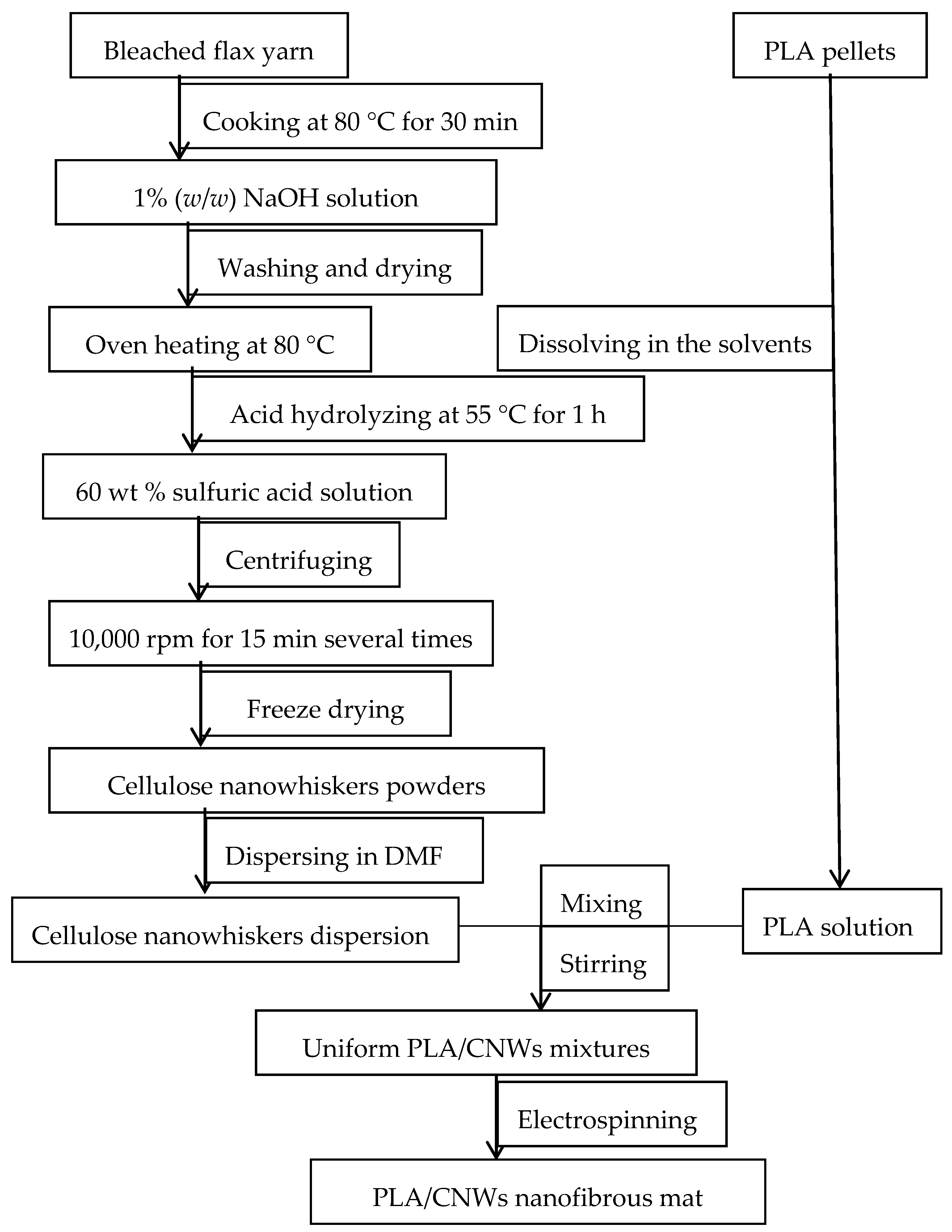
2.2. CNWs Preparation

CNWs were isolated from flax fibers via an acid hydrolysis method. Bleached flax yarns were boiled in distilled water for 30 min and oven-dried to a constant weight. Dried yarns were then soaked for 30 min in 1% (w/w) NaOH aqueous solution at 80 °C, and washed again in running water (i.e., in an alkali-free environment). An aqueous suspension of CNWs was prepared by acid hydrolysis for 1 h in 60 wt % sulfuric acid at 55 °C with continuous stirring. After the completion of hydrolysis, the flask with the suspension was cooled in ice-cold water. The aqueous suspension of fibers was further diluted and repeatedly washed by centrifugation prior to neutralization with 1.0 wt % NaOH aqueous solution. The suspension was then freeze-dried for 48 h before use. The entire process is elaborated in Figure 1.
The concentrated aqueous CNWs suspension and freeze-dried CNWs powders are depicted in Figure 2. The incorporation of sulphate groups along the surface of the crystallites results in a negative charge of the surface. This anionic stabilization via attraction/repulsion forces of electrical double layers at the crystallites is the main reason for the stability of colloidal suspensions of crystallites. The loosely packed powders are easily dispersed in water or solvents with ultrasonic treatment, which is feasible for obtaining homogeneous mixtures with polymer solutions.

2.3. Preparation of PLA/CNWs Nanofibrous Mat

A weighed amount of CNWs was dispersed in DMF at ambient temperature. Then, appropriate amounts of THF and PLA were added and the mixture was stirred for several hours. The final dispersion contained 5.0 or 10.0 wt % CNWs with respect to the total amount of PLA and CNWs, and 12% PLA/CNWs solution. The masses of components and solvents are presented in Table 1. Electrospun mats were obtained by applying a high voltage between a needle tip and a grounded collector. Nanofibrous mats were collected on an aluminum foil by a needle tip-to-collector distance of 100 mm with an applied voltage of 10–15 kV and a solution feed rate of 1.0–1.5 mL h−1. When a high voltage was applied to the metal syringe needle, electrical charge was built up on the solution surface. The charge was attracted towards an electrically grounded collector, in our case, covered by a piece of aluminum foil. As the charge travelled to the grounded collector, an electrified thin jet of polymer solution was pulled from the needle. After the solution left the syringe, the solvent evaporated rapidly and a very thin stream of elongated polymer fibers went toward the collector. Thin fibers were thereby randomly deposited on the collector surface. The electrospun nanofibrous mat was peeled with care from the aluminum foil for subsequent testing use.

2.4. Characterization Methods

The structures of CNWs and PLA/CNWs nanofibers were investigated using a transmission electron microscope (TEM—Philips CM 12, Holland, The Netherlands) at the accelerating voltage of 100 kV. A droplet of the diluted suspension was allowed to float on and eventually flow through a copper grid covered with a carbon film. The samples were then stained by allowing the grids to float in a 2.0 wt % solution of uranyl acetate for 1 min. TEM observation of composite nanofibers was performed by mounting the fibrous mat in epoxy resin, followed by negatively staining with osmium tetroxide vapor and solution of uranyl acetate, respectively.
X-ray diffraction (XRD–Bruker D 8 Advance, Karlsruhe, Germany) measurements were performed using Cu Kα radiation (scan speed of 0.02°·s−1 from the diffraction angle 2θ = 5°–50°) at 40 kV and 40 mA.
The thermal behavior of the fibers was characterized by a differential scanning calorimeter (DSC, TA instrument Q1000, New Castle, DE, USA) using a heat/cooling cycle between 0 and 180 °C at a heating/cooling rate of 10 °C/min. A Fourier transform infrared (FTIR Nicolet 8700, Mettler-Toledo, LLC, Columbus, OH, USA) spectroscope based on attenuated total reflectance (ATR) was employed to analyze the chemical structures of the samples. All spectra were collected with 4 cm−1 wave number resolution after 64 continuous scans at a wavelength range of 4000–600 cm−1.
Thermal stability was assessed with a thermogravimetric analysis (TGA, Q5000, New Castle, DE, USA). Samples were heated in open platinum pans from room temperature to 600 °C, under a nitrogen atmosphere to avoid thermoxidative degradation, at a heating rate of 10 °C/min.
The degree of crystallinity (X) was evaluated from the DSC data according to Equation (1) [13]:
x % = Δ H m Δ H c Δ H m 0 × X P L A × 100 %
where Δ H m and Δ H c are melting and crystallization enthalpies, respectively; Δ H m 0 is 93.6 J/g for 100% crystalline PLA crystals [13]; and XPLA is the weight fraction of PLA matrices in their composites.
The morphology of the electrospun nanofibers was studied using a field emission scanning electron microscope (FE-SEM, FEI XL30s) with an accelerating voltage of 5 kV.
To calculate the water absorption, the samples were immersed in distilled water at room temperature for 24 h after being dried in the oven at 80 °C until no weight change was observed. Subsequently, the samples were taken out, blotted with filter paper to absorb the excess water on the surface, and weighed in a precise balance. The water absorption ratio (g/g) was determined according to the following equation:
Water absorption ratio = (WtW0)/W0
where W0 is the mass of the dried sample and Wt is the mass of the swollen sample at time t (here t = 24 h).

3. Results and Discussion

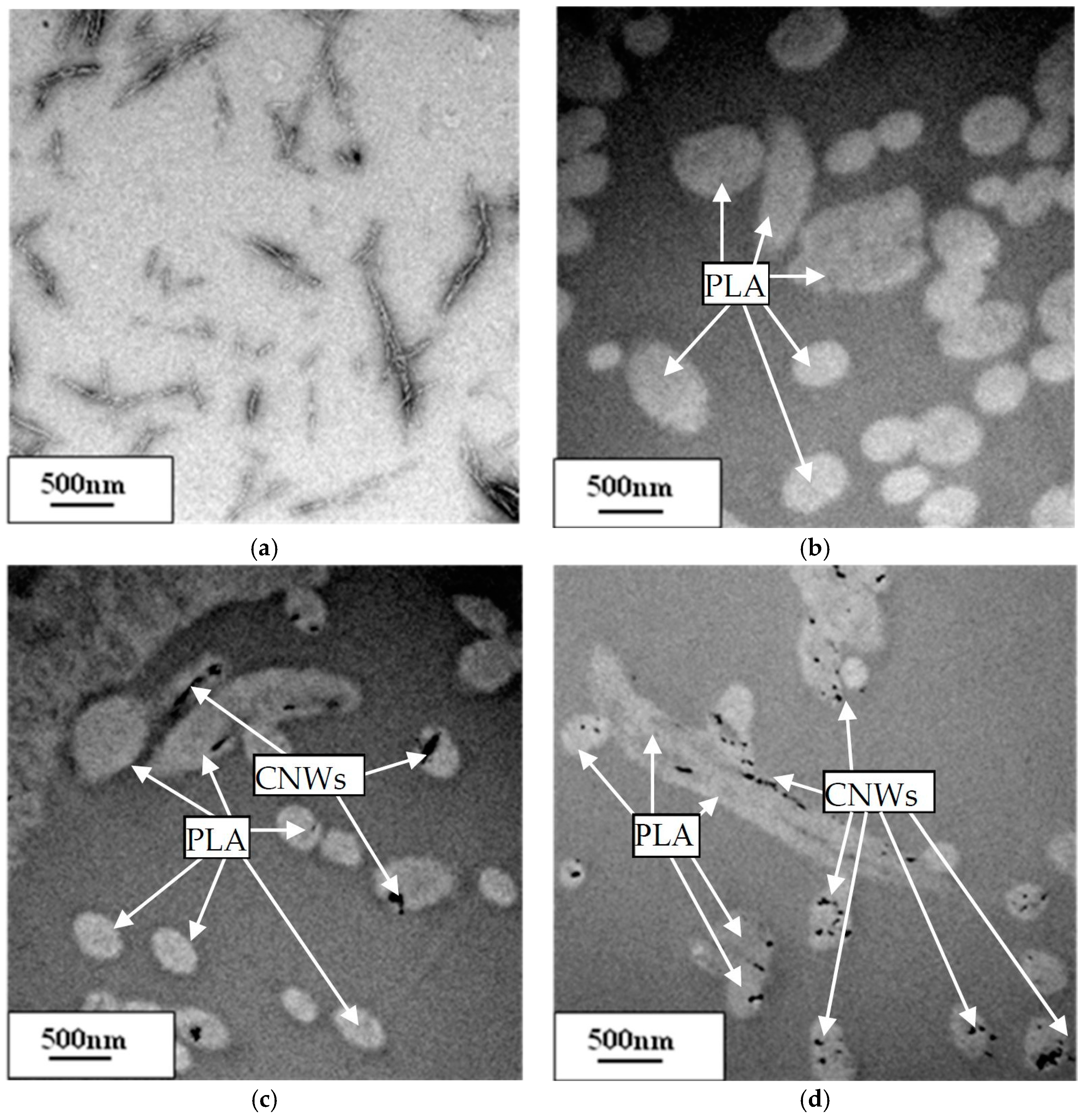
3.1. Morphological Characterizations of CNWs

The average diameter and length for individual cellulose fibers were measured to be 20 and 300 nm, respectively. The sizes of CNWs are dependent on the source of raw materials and their production methods. CNWs from cotton show lower aspect ratios between 10–12 [14,15], as opposed to that of CNWs from tunicin at 200 [16]. TEMPO-oxidization can produce CNWs with a high aspect ratio relative to those produced using sulfuric acid hydrolysis [17]. As it is well known, fillers with high aspect ratios conventionally are crucial for an efficient reinforcement effect in polymer matrices.

3.2. Characterization of Electrospun PLA/CNWs Composite Nanofibers
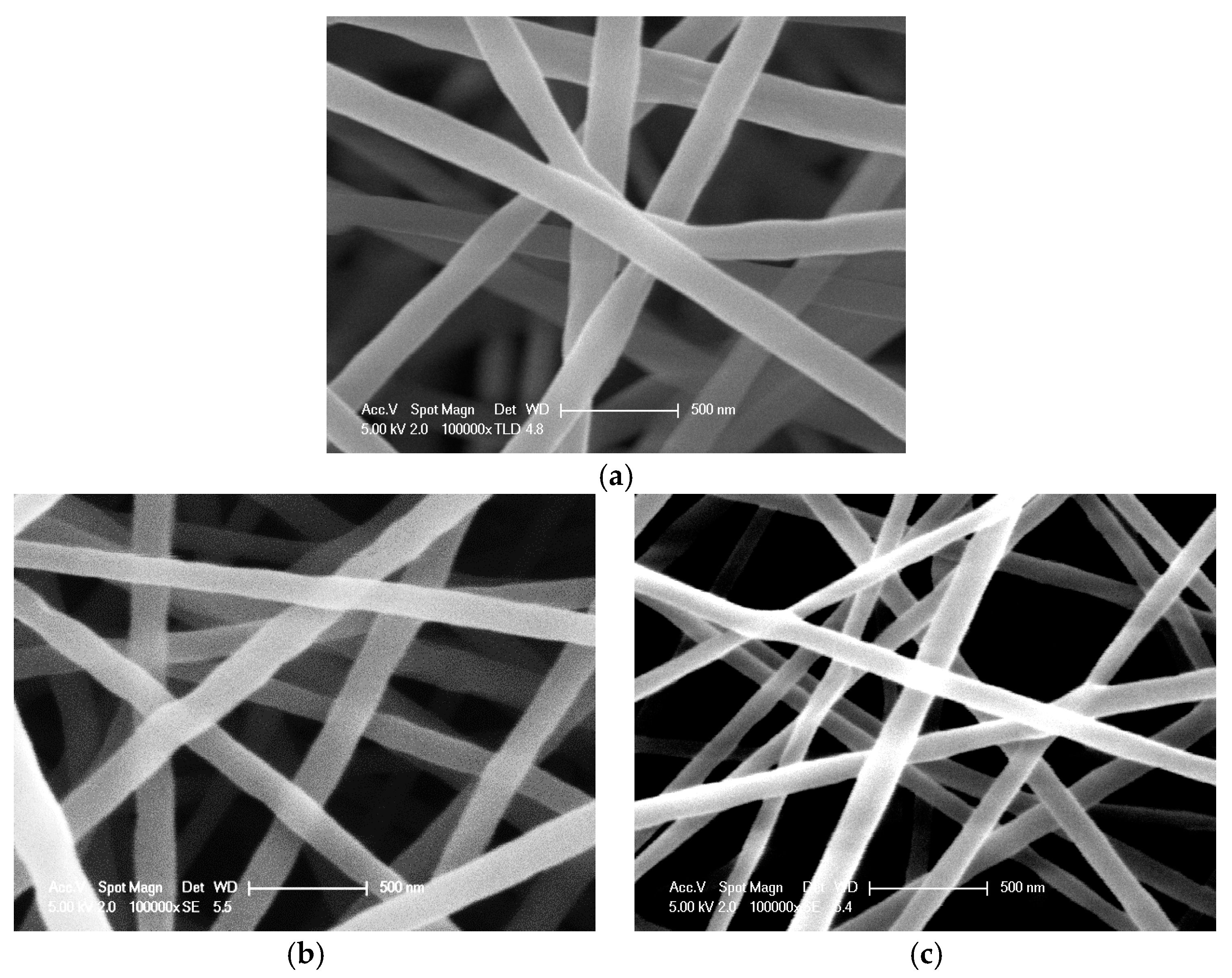
3.2.1. Morphology

CNWs show a significant reinforcing effect in polymeric nanofibers, which results from the synergistic effect of solution flow and electric charge that induced the orientation of nanofillers along the fiber tailored direction during the electrospinning process. The reinforcement of fillers is strongly dependent on good filler distribution within matrix fibers. The fibrous morphology is usually observed via scanning electron microscopy (SEM). The SEM morphology of pure PLA and PLA/CNWs composite nanofibrous mats produced by electrospinning is depicted in Figure 3, and is clearly indicative of typical porous structures. Pure PLA nanofibers are relatively uniform with average fiber diameters of approximately 202 nm. The diameters of PLA/10CNWs composite nanofibers are slightly smaller (at 129 nm) than those of PLA/5CNWs counterparts (at 170 nm) due to the decrease in the total concentration of mixtures, resulting from the replacement of PLA with CNWs.
No CNWs appear to protrude from the outer surface of the PLA fibers, implying that they are completely embedded into the PLA matrices. They may be aligned along the fiber axis through the entire fibers during the electrospinning process because CNWs can also be aligned in the electrical field [18]. Similar behavior has been observed for electrospun polymer/CNT composite nanofibers [19,20]. This distribution behavior makes a significant contribution to the mechanical strength and modulus of matrix fibers. It arises from more effective reinforcements of nanofillers within matrices as well as better interfacial bonding between nanofillers and matrix fibers, when compared with polymer nanocomposites produced by solution casting and melt compounding methods.
The existence of CNWs in morphological structures is further detected under TEM, as exhibited in Figure 4a. The sulfuric acid hydrolysis of cellulose causes the breakdown of the fibers into rod-like fragments with a diameter of 20 nm and length of 300 nm. Amorphous phases were selectively hydrolyzed, and crystalline phases remained unaffected. Stained CNWs (i.e., dark dots represent the cross sections of CNWs) are well aligned along PLA nanofibers (i.e., long bright fibers) and uniformly distributed within matrix fibers. The distribution of nanofillers in electrospun nanofibers is associated with the material selection of solvents and polymer matrices. CNWs can be uniformly dispersed in polar-group solvents, such as water, DMF, etc. [21,22]. Rojas et al. found that 9 wt % CNWs were distributed on the outer surface of polystyrene (PS) nanofibers due to centrifugal effects during electrospinning [11]. CNWs aggregated in the center of polymethyl methacrylate (PMMA) nanofibers by using an etching method as mentioned by Dong et al. [12].

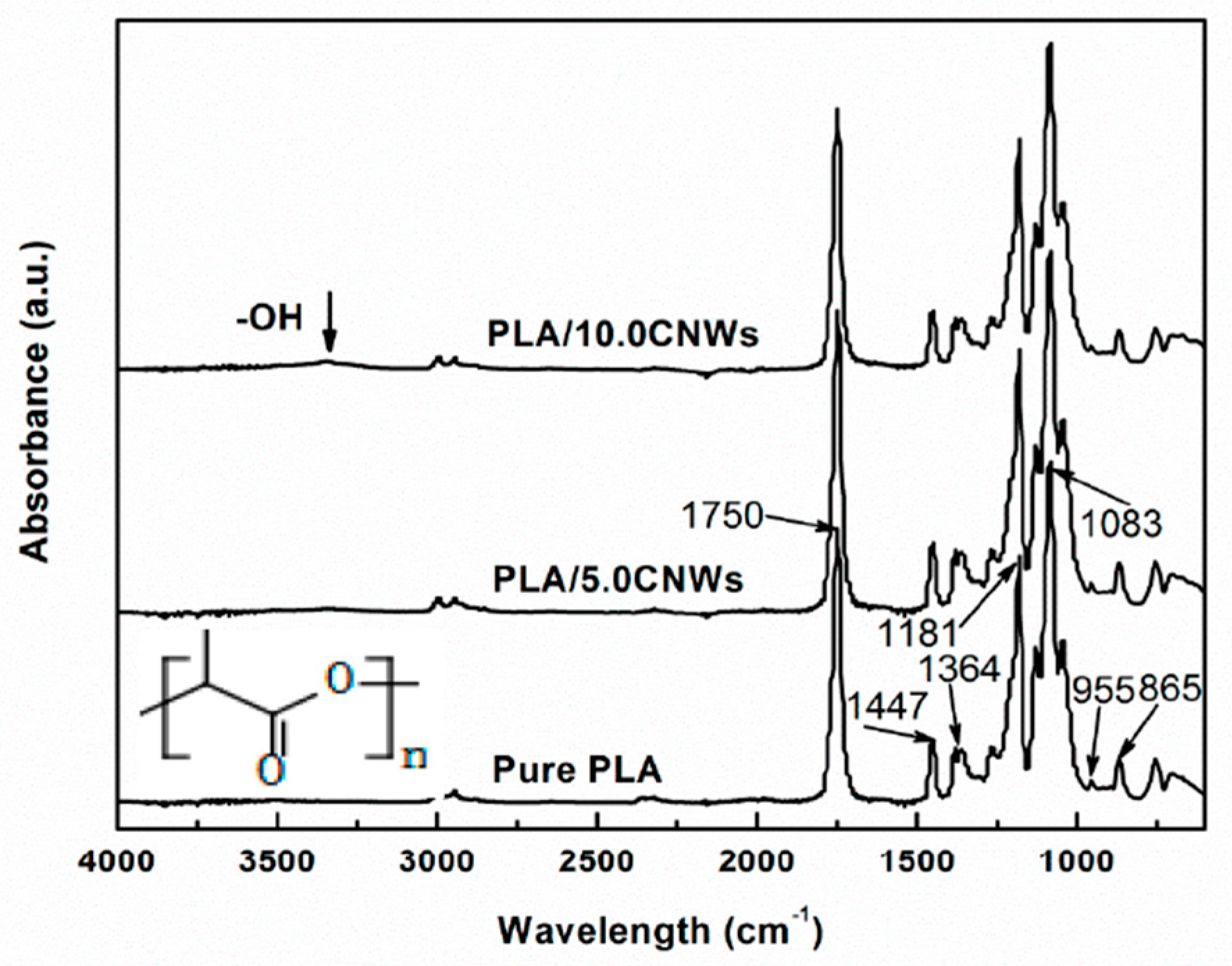
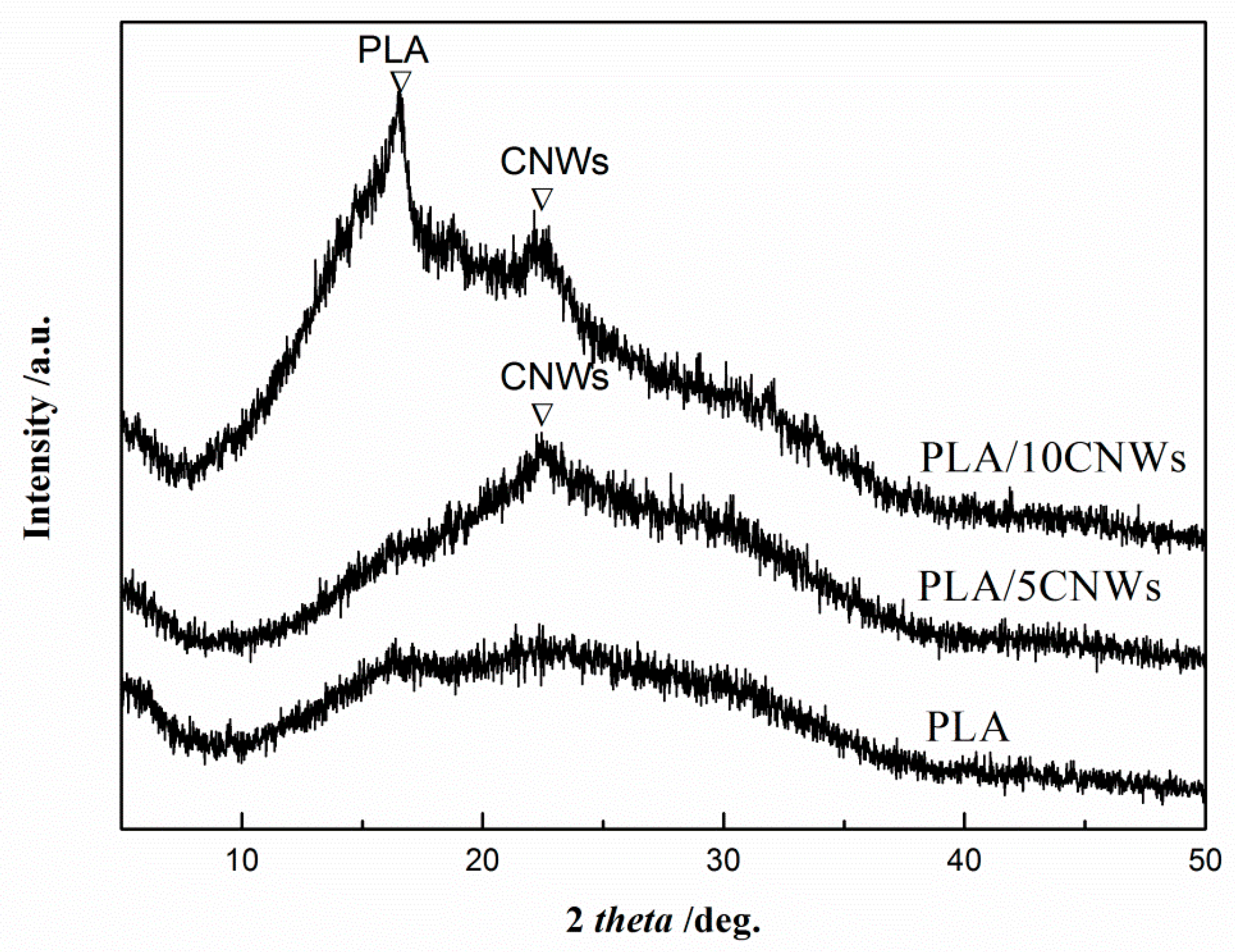
3.2.2. Structural Analysis

FTIR analysis was carried out to confirm the presence of CNWs in PLA nanofiber mats and further assess their interactions. PLA is a semicrystalline polymer with the chemical formula of (C3H4O2)n. As shown in Figure 5, The needle-like peaks at 1737 and 1165 cm−1 are assigned to the carbonyl stretching C=O and stretching vibration of C–O in PLA chains. A mountainous triplet of peaks at 1110, 1072, and 1025 cm−1 correspond to C–O stretching vibrations [23]. The absorption bands at 921 and 908 cm−1 are characteristic of PLA/CNWs composite nanofibers. This phenomenon signifies their prevalent amorphous structures [24]. However, according to the relative decrease in the peak intensity of the amorphous phase at 955 cm−1, it is elucidated that the degree of crystallinity increases as the CNW content increases. Weak bands between 3550 and 3200 cm−1, which are assigned to typical stretching –OH vibrations in cellulose, are present in the spectra of composite mats with the addition of 5.0 and 10.0 wt % CNWs. This finding confirms the incorporation of CNWs into PLA matrix fibers during the electrospinning process. The peaks of composite nanofibers show no difference from those of pure PLA, which suggests that little interaction takes place between CNWs and PLA.
Figure 6 shows XRD patterns of pure PLA and PLA/CNWs composite mats. Pure PLA mat exhibits a broad diffraction pattern without the obviously sharp peaks of crystalline PLA, indicating their dominant amorphous structures. This means that no detectible crystallization for the pure PLA nanofibers occurs due to the rapid evaporation rate of solvents. Moreover, polymeric chains under the high elongation rate have less time to form crystalline lamellae, leading to a lower degree of crystallinity. However, sharp peaks appear for composite mats with the inclusion of 5.0 and 10.0 wt % CNWs. The tiny peak presented at 22.4° is the typical diffraction of crystalline CNWs because CNWs generally possess two typical peaks at 15°–16° and 22.4°, and the latter is more intense [25]. The intense peak at 16.6° for PLA/10CNWs is evident, which belongs to the peaks of crystalline PLA to enhance the crystallinity degree of PLA [26]. This peak is much more pronounced than that of PLA nanofibers with addition of 7.5% CNWs [27]. The increased crystallinity degree of PLA is attributed to the inclusion of a high content of CNWs. The degree of crystallinity of PLA can be calculated according to the melting enthalpy in further-mentioned DSC curves.

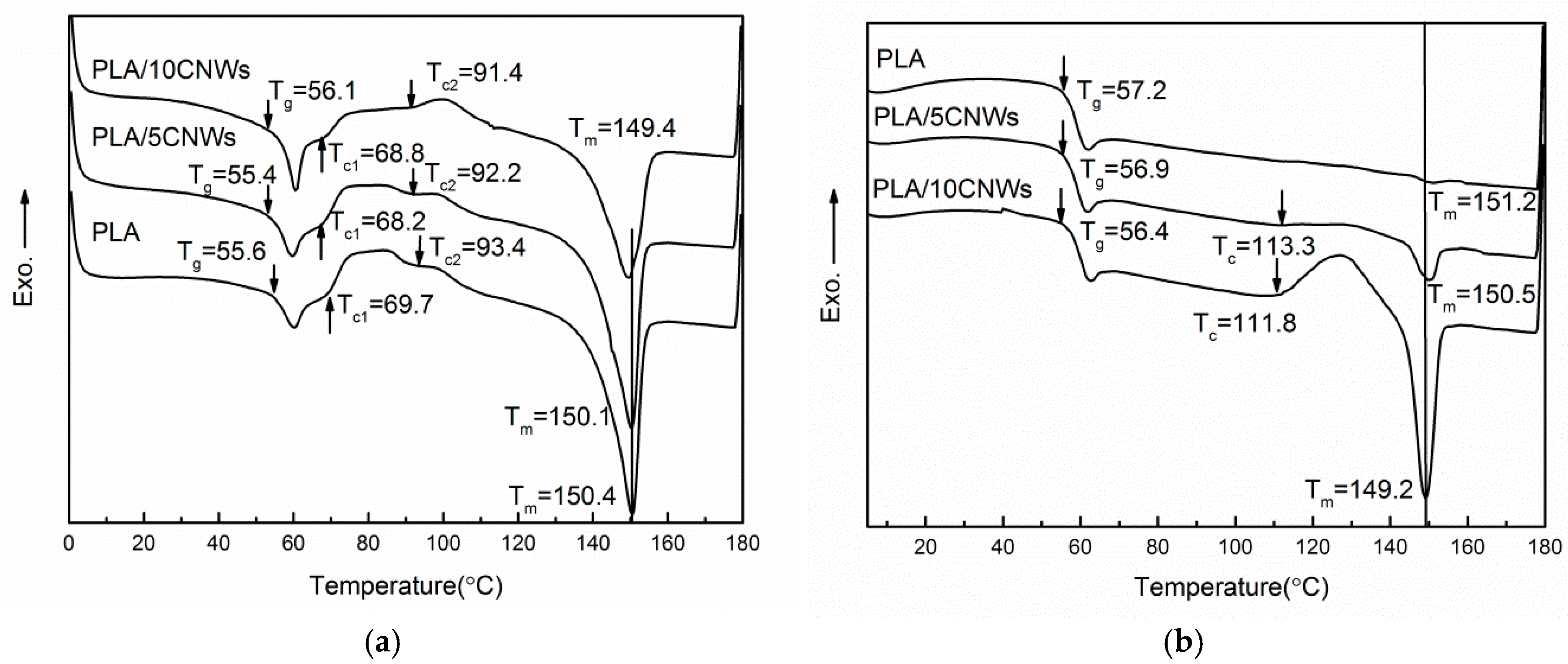
3.2.3. DSC Characterizations

Thermal properties of electrospun nanofibers can be determined from the characteristic exothermic or endothermic reactions on DSC curves. When heated, electrospun fibers exhibit glass transition, followed by cold crystallization and melting processes. The thermal behaviors of electrospun nanofibers shown in Figure 5 are quite similar to those of PLA/CNWs composite nanofibers [28]. The glass transition temperatures (Tg) and melting temperatures (Tm) of all electrospun nanofibers occur at about 55 and 150 °C, respectively, regardless of processing methods and CNWs concentration. However, their characteristic crystallization parameters demonstrate a great difference from bulk films prepared by solution casting and melting compounding methods. The onset crystallization temperatures (Tc) were found to be around 69.7, 68.2, and 68.8 °C, for neat PLA nanofibers as well as PLA/5CNWs and PLA /10CNWs composite nanofibers, respectively. These temperatures for as-spun nanofibers are over 30 °C lower than those composite films manufactured using solution cast and melt compounding (over 100 °C) [28,29]. This is because molecular chains in electrospun PLA nanofibers are highly oriented compared to the randomly coiled chains in PLA cast films [30]. The rapid drawing and solidification of polymer jets leads to the nonequilibrium conformation and highly orientated polymer chains along the axis of the long matrix nanofibers during the electrospinning process. Such imperfection gives rise to decreases in crystallization temperatures. Oh et al. reported that the onset temperature of cold crystallization decreases as the draw ratio increases, resulting from the initial cold crystallization behavior of PLA matrices that is enhanced by the presence of strain-induced crystallinity [31,32]. The crystallization takes place at lower temperatures immediately after the glass transition, which can be attributed to the presence of numerous crystal nuclei. Therefore, electrospun nanofibers showed different properties from those of PLA/CNWs composite films with a low degree of crystallinity prepared by melt compounding. The overlapping crystallization peaks with a wide temperature range of electrospun nanofibers also vary from those of films obtained via conventional solution casting and melt compounding with a single exothermic peak. This phenomenon indicates the complexity of molecular structures of electrospun nanofibers. It may be associated with the formation of polymorphic crystals, which will be further investigated in our subsequent work.
The effects of CNWs on the cold crystallization of PLA nanofibers and PLA/CNWs composite nanofibers are shown in Figure 7a. The cold crystallization of neat PLA mat appears to present two overlapping peaks. The decrease in Tc values with the addition of CNWs may result from the existence of more nuclei because CNWs can be effective nucleating agents to accelerate the PLA cold crystallization process [33,34]. The degree of crystallinity in electrospun PLA mat is very low as listed in Table 1, indicating that the majority of the chains are in the amorphous phase. It can be easily understood that the rapid solidification of stretched chains under a high elongation rate at the later stage of electrospinning may hinder the crystal development owing to insufficient time for molecular chains to form crystal structures. These two crystallization peaks were observed to shift to lower temperatures at 69.7 and 93.4, 68.2 and 92.2, as well as 68.8 and 91.4 °C for pure PLA nanofibers and PLA/CNWs composite nanofibers at CNWs contents of 5.0 and 10 wt %, respectively, as shown in Table 2.
In order to eliminate the thermal history for the samples, the fibers were heated above the melting temperature of 180 °C during the first heating cycle, and cooled below glass temperature and reheated above the Tg again during the second heating cycle. The DSC curves are shown in Figure 7b. The curves at the second heating cycle demonstrate significant differences in cold crystallization and melting peaks from those at the first cycle. Apparently, as-spun nanofibers with well-oriented molecular chains can be easily destroyed by transforming fibrous structures into polymeric melt upon the melting stage. Pure PLA nanofibers were shown to undergo multiple stages of thermal effect from glass transition, weak cold crystallization to a melting process with a weak and wide melting peak observed at 151.2 °C, whereas PLA/CNWs composite nanofibers reveal distinct high Tc values of 113.8 and 111.3 °C, as well as Tm values of 150.5 and 149.2 °C for PLA/CNWs composite nanofibers reinforced with 5% and 10% CNWs, respectively. The apparent cold crystallization of composite mats is due to embedded CNWs facilitating the nucleation of PLA crystals in the cold crystallization process, thus leading to the decrease of Tc and the increase in the degree of crystallization. This nucleating effect of CNWs manifested in both electrospun nanofibers and subsequently quenched samples in that composite mat induce increases in the degree of crystallinity in both heating cycles. The degree of crystallinity increases from 6.0% for electrospun PLA nanofibers to 14.1% and 21.6% (tabulated in Table 2) for PLA/5CNWs and PLA/10CNWs composite nanofibers, respectively. These crystallinity values are consistent with the XRD results. On the other hand, the degrees of crystallinity for the quenched samples at the second heating cycle are only 0.2%, 0.6%, and 3.5% for pure PLA nanofibers, PLA/5CNWs, and PLA/10CNWs composite nanofibers, respectively, which are much lower than those of the counterparts at the first heating cycle. The orientation of molecular chains and nanofiber elongation during electrospinning are responsible for the increase in the degree of crystallinity for electrospun nanofibers.

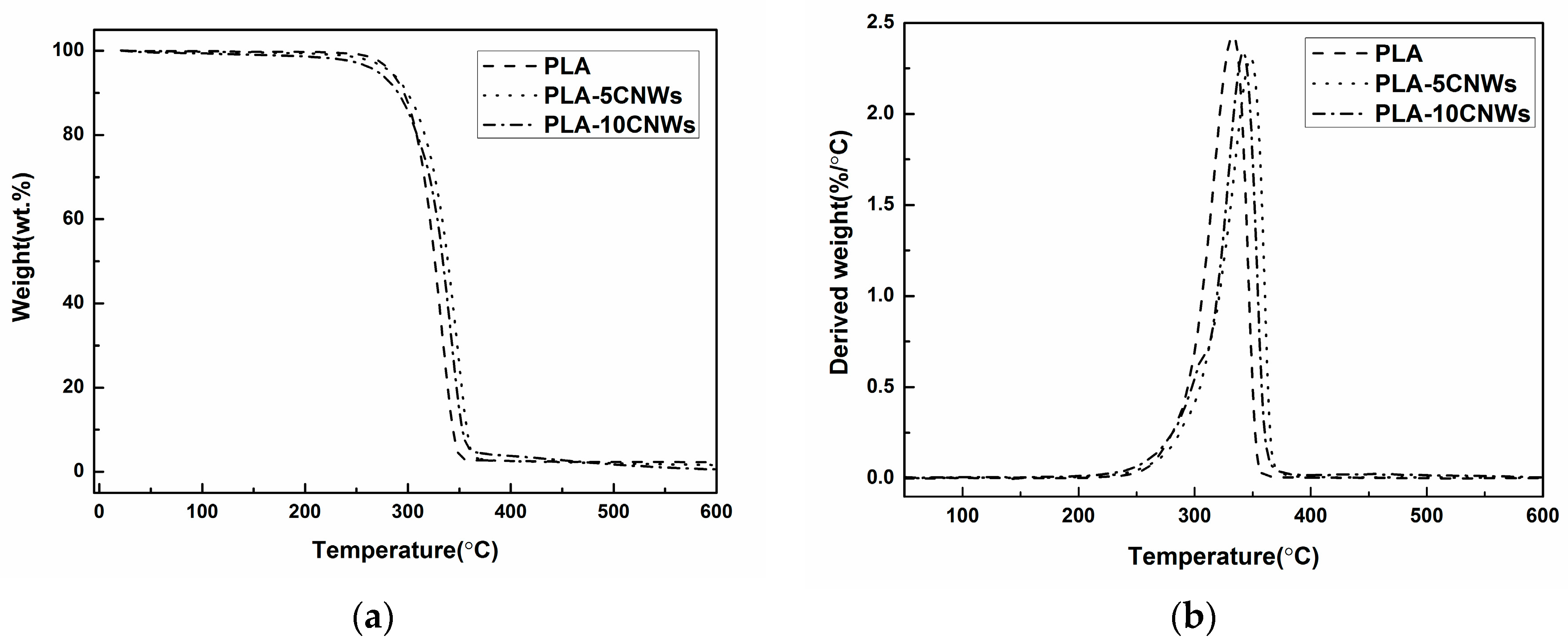
3.2.4. Thermal Degradation

Figure 8 shows TGA and DTGA (derivative TGA) curves of PLA and PLA/CNWs composite mats. The main degradation behaviors of PLA and PLA/CNWs composite mats are similar. The decomposition starts at around 260 °C, followed by a rapid weight loss of over 96% at the temperatures around 350–360 °C. The initial decomposition temperature is dependent on the molecular weight and crystallinity of PLA. A slightly higher weight remains for composite mats due to the existence of CNWs, which are more stable at the temperature range over 310 °C than is pure PLA. The composite nanofibers including cellulose nanowhiskers show a little more weight loss than neat PLA nanofibers at the temperature below 300 °C, which is ascribed to the faster degradation rate of cellulose nanowhiskers than of PLA nanofibers. The weight loss increases with an increase in the concentration of cellulose nanowhiskers. Above 300 °C, the composite nanofibers show improved thermal stability due to the low degradation rate of cellulose nanowhiskers, corresponding to the lower peak intensity and the shift peak position to a high temperature in the DTGA curves [35].

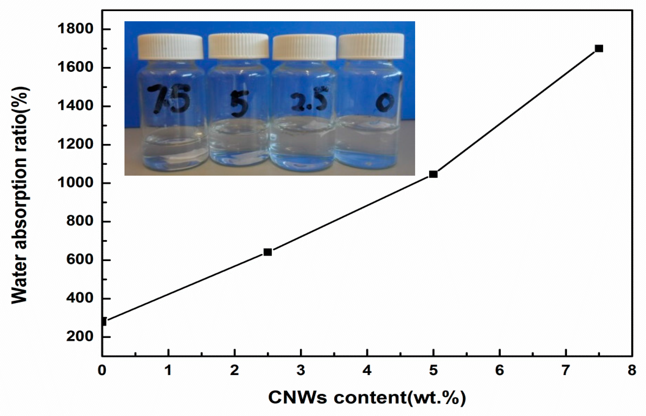
3.2.5. Water Absorption

In addition to the reinforcing effect of nanofillers, the water wettability of polymer matrices can be improved with the addition of hydrophilic CNWs. PLA has been approved by Food and Drug Administration (FDA) for clinical use such as in surgical sutures [36]. However, the hydrophobic nature of electrospun PLA nanofibers restricts their applications in tissue scaffolding because cells may attach and proliferate less well than on matrices with good wettability [37]. The use of hydrophilic nanomaterials or polymers will improve the water wettability of hydrophobic polymeric nanofibers [38,39]. Water absorption or retention is a simple and direct gravimetric test for determining the maximum amount of fluid absorption and fluid retention on tested materials. The water absorption ratio of composite nanofibers greatly increases with an increase in the CNWs content from 2.5 to 7.5 wt %, as illustrated in Figure 6. The water absorption ratio of pure PLA nanofibrous mat is over 200% owing to its porous structure. This ratio reaches over 1600% with the addition of 7.5% CNWs, which is 8 times that of the neat PLA mat. This improvement in water absorption is beneficial to applications in tissue engineering or membranes. The immersion state of the pure PLA mat and PLA/CNWs composite mats are also shown in Figure 9. It is evidently seen that the PLA/CNWs composite mat with 5.0 and 7.5 wt % CNWs inclusions dropped down to the bottom of the vials, whereas mats of pure PLA and PLA/CNWs composites with 2.5 wt % CNWs still floated on the top surface of the water. This indirectly proves that the water absorption ability of the PLA mat is improved with the incorporation of CNWs.

4. Conclusions

Rod-shaped CNWs with lateral and longitudinal dimensions of 30 and 300 nm, respectively, are favorable for preparing PLA/CNWs composite nanofibers without clogging the needle during the electrospinning process. The composite nanofibers are thinner than their pure PLA counterparts due to their lower solution concentration by adding CNWs. The nanofibers show smooth surfaces without any obvious protrusion of CNWs on the outer surfaces of the PLA nanofibers. The CNWs are well aligned along the PLA nanofibers and uniformly distributed within matrix fibers. Electrospun PLA nanofibers and PLA/CNWs composite nanofibers show lower crystallization temperatures and higher degrees of crystallinity than the quenched samples. The addition of CNWs has also been found to effectively enhance the water absorption of PLA nanofibers. CNWs and their polymer composite nanofibers can offer great potential for widespread applications from biomedical engineering, to sensors, to nanofiltration.

Acknowledgments

The authors would like to thank the Key Laboratory of Advanced Display and System Applications of Ministry of Education, Shanghai University (China) for various support.

Author Contributions

W.L. and X.L. conceived and designed the experiments; W.L. and Y.B. performed the experiments; Y.D. and D.L. analyzed the data; Z.L. and Y.B. contributed reagents/materials/analysis tools; W.L., D.L., and Y.D. wrote the paper.

Conflicts of Interest

The authors declare no conflicts of interest.

References

  1. Eichhorn, S.J.; Dufresne, A.; Aranguren, M.; Marcovich, N.E.; Capadona, J.R.; Rowan, S.J.; Weder, C.; Thielemans, W.; Roman, M.; Renneckar, S.; et al. Current international research into cellulose nanofibres and nanocomposites. J. Mater. Sci. 2010, 45, 1–33. [Google Scholar] [CrossRef]
  2. Ding, B.; Wang, M.; Yu, J.; Sun, G. Gas sensors based on electrospun nanofibers. Sensors 2009, 9, 1609–1624. [Google Scholar] [CrossRef] [PubMed]
  3. Bhattaraia, S.R.; Bhattarai, N.; Yi, H.K.; Hwang, P.H.; Cha, D.I.; Kim, H.Y. Novel biodegradable electrospun membrane: Scaffold for tissue engineering. Biomaterials 2004, 25, 2595–2602. [Google Scholar] [CrossRef]
  4. Hou, H.; Ge, J.J.; Zeng, J.; Li, Q.; Reneker, D.H.; Greiner, A. Electrospun polyacrylonitrile nanofibers containing a high concentration of well-aligned multiwall carbon nanotubes. Chem. Mater. 2005, 17, 967–973. [Google Scholar] [CrossRef]
  5. Ji, J.; Sui, G.; Yu, Y.; Liu, Y.; Lin, Y.; Du, Z. Significant improvement of mechanical properties observed in highly aligned carbon-nanotube-reinforced nanofibers. J. Phys. Chem. C 2009, 113, 4779–4785. [Google Scholar] [CrossRef]
  6. Park, W.I.; Kang, M.; Kim, H.S.; Jin, H.J. Electrospinning of poly (ethylene oxide) with bacterial cellulose whiskers. Macromol. Symp. 2007, 249–250, 289–294. [Google Scholar] [CrossRef]
  7. Peresin, M.S.; Habibi, Y.; Zoppe, J.O.; Pawlak, J.; Rojas, O.J. Nanofiber composites of polyvinyl alcohol and cellulose nanocrystals: Manufacture and characterization. Biomacromolecules 2010, 11, 674–681. [Google Scholar] [CrossRef] [PubMed]
  8. Hong, J.H.; Jeong, E.H.; Lee, H.S.; Baik, D.H.; Seo, S.W.; Youk, J.H. Electrospinning of polyurethane/organically modified montmorillonite nanocomposites. J. Polym. Sci. Part B Polym. Phys. 2005, 43, 3171–3177. [Google Scholar] [CrossRef]
  9. Zoppe, J.O.; Peresin, M.S.; Habibi, Y.; Venditi, R.; Rojas, O.J. Reinforcing poly (ε-caprolactone) nanofibers with cellulose nanocrystals. Appl. Mater. Interfaces 2009, 1, 1996–2004. [Google Scholar] [CrossRef] [PubMed]
  10. Shi, Q.F.; Zhou, C.J.; Yue, Y.Y.; Guo, W.; Wu, Y.; Wu, Q. Mechanical properties and in vitro degradation of electrospun bio-nanocomposite mats from PLA and cellulose nanocrystals. Carbohyd. Polym. 2012, 90, 301–308. [Google Scholar] [CrossRef] [PubMed]
  11. Rojas, O.J.; Montero, G.A.; Habibi, Y. Electrospun nanocomposites from polystyrene loaded with cellulose nanowhiskers. J. Appl. Polym. Sci. 2009, 113, 927–935. [Google Scholar] [CrossRef]
  12. Dong, H.; Strawhecker, K.E.; Snyder, J.F.; Orlicki, J.A.; Reiner, R.S.; Rudie, A.W. Cellulose nanocrystals as a reinforcing material for electrospun poly(methyl methacrylate) fibers: Formation, properties and nanomechanical characterization. Carbohd. Polym. 2012, 87, 2488–2495. [Google Scholar] [CrossRef]
  13. Ke, T.Y.; Sun, X.Z. Physical properties of poly (lactic acid) and starch composites with various blending ratios. Cereal. Chem. 2000, 77, 761–768. [Google Scholar] [CrossRef]
  14. Martins, M.; Teixeira, E.M.; Corrêa, A.C.; Ferreira, M.; Mattoso, L.H.C. Extraction and characterization of cellulose whiskers from commercial cotton fibers. J. Mater. Sci. 2011, 46, 7858–7864. [Google Scholar] [CrossRef]
  15. Roohani, M.; Habibi, Y.; Belgacem, N.; Ebrahim, G.; Karimi, A.; Dufresne, A. Cellulose whiskers reinforced polyvinyl alcohol copolymers nanocomposites. Eur. Polym. J. 2008, 44, 2489–2498. [Google Scholar] [CrossRef]
  16. Angles, M.N.; Dufresne, A. Plasticized starch/tunicin whiskers nanocomposites. 1. Structural analysis. Macromolecules 2000, 33, 8344–8353. [Google Scholar] [CrossRef]
  17. Sun, X.; Wu, Q.; Ren, S.; Lei, T. Comparison of highly transparent all-cellulose nanopaper prepared using sulfuric acid and TEMPO-mediated oxidation methods. Cellulose 2015, 22, 1123–1133. [Google Scholar] [CrossRef]
  18. Habibi, Y.; Heim, T.; Douillard, R. AC electric field-assisted assembly and alignment of cellulose nanocrystals. J. Polym. Sci. Part B Polym. Phys. 2008, 46, 1430–1436. [Google Scholar] [CrossRef]
  19. Lu, P.; Hsieh, Y.L. Multiwalled carbon nanotube (MWCNT) reinforced cellulose fibers by electrospinning. Appl. Mater. Interfaces 2010, 2, 2413–2420. [Google Scholar] [CrossRef] [PubMed]
  20. Kannan, P.; Eichhorn, S.J.; Young, R.J. Deformation of isolated single-wall carbon nanotubes in electrospun polymer nanofibers. Nanotechnol 2007, 18, 235707. [Google Scholar] [CrossRef]
  21. Beck, S.; Bouchard, J.; Berry, R. Dispersibility in water of dried nanocrystalline cellulose. Biomacromolecules 2012, 13, 1486–1494. [Google Scholar] [CrossRef] [PubMed]
  22. Van den Berg, O.; Capadona, J.R.; Weder, C. Preparation of homogeneous dispersions of tunicate cellulose whiskers in organic solvents. Biomacromolecules 2007, 8, 1353–1357. [Google Scholar] [CrossRef] [PubMed]
  23. Mai, T.T.T.; Nguye, T.T.T.; Le, Q.D.; Nguyen, T.N.; Ba, T.C.; Nguyen, H.B.; Phan, T.B.H.; Tran, D.L.; Nguyen, X.P.; Park, J.S. A novel nanofiber Cur-loaded polylactic acid constructed by electrospinning. Adv. Nat. Sci. Nanosci. Nanotechnol. 2012, 3, 025014. [Google Scholar]
  24. Ribeiro, C.; Sencadas, V.; Costa, C.M.; Ribelles, J.L.G.; Lanceros-Mendez, S. Tailoring the morphology and crystallinity of poly (l-lactide acid) electrospun membranes. Sci. Technol. Adv. Mater. 2011, 12, 015001. [Google Scholar] [CrossRef] [PubMed]
  25. Lamaminga, J.; Hashima, R.; Sulaimana, O.; Leha, C.P.; Sugimoto, T.; Nordina, N.A. Cellulose nanocrystals isolated from oil palm trunk. Carbohyd. Polym. 2015, 127, 202–208. [Google Scholar] [CrossRef] [PubMed]
  26. Yasuniwa, M.; Sakamo, K.; Ono, Y.; Kawahara, W. Melting behavior of poly (l-lactic acid): X-ray and DSC analyses of the melting process. Polymer 2008, 49, 1943–1951. [Google Scholar] [CrossRef]
  27. Liu, D.Y.; Yuan, X.W.; Bhattcharyya, D. The effects of cellulose nanowhiskers on electrospun poly (lactic acid) nanofibers. J. Mater. Sci. 2012, 47, 3159–3165. [Google Scholar] [CrossRef]
  28. Espino-Pérez, E.; Bras, J.; Ducruet, V.; Guinault, A.; Dufresne, A.; Domenek, S. Influence of chemical surface modification of cellulose nanowhiskers on thermal, mechanical, and barrier properties of poly (lactide) based bionanocomposites. Eur. Polym. J. 2013, 49, 3144–3154. [Google Scholar] [CrossRef]
  29. Raquez, S.J.M.; Murena, Y.; Goffin, A.L.; Habibi, Y.; Ruelle, B.; DeBuyl, F.; Dubois, P. Surface-modification of cellulose nanowhiskers and their use as nanoreinforcers into polylactide: A sustainably-integrated approach. Comp. Sci. Technol. 2012, 72, 544–549. [Google Scholar] [CrossRef]
  30. Zong, X.; Kim, K.; Fang, D.; Ran, S.; Hsiao, B.S.; Chu, B. Structure and process relationship of electrospun bioabsorbable nanofiber membranes. Polymer 2002, 43, 4403–4412. [Google Scholar] [CrossRef]
  31. Oh, M.O.; Kim, S.H. Conformational development of polylactide films induced by uniaxial drawing. Polym. Int. 2014, 63, 1247–1253. [Google Scholar] [CrossRef]
  32. Stoclet, G.; Seguela, R.; Lefebvre, J.M.; Elkoun, S.; Vanmansart, C. Strain-induced molecular ordering in polylactide upon uniaxial stretching. Macromolecules 2010, 43, 1488–1498. [Google Scholar] [CrossRef]
  33. Salmeron, S.M.; Mathot, V.B.F.; Vanden, P.G.; Gomez, R.J.L. Effect of the cooling rate on the nucleation kinetics of poly(l-lactic acid) and its influence on morphology. Macromolecules 2007, 40, 7989–7997. [Google Scholar] [CrossRef]
  34. Pei, A.; Zhou, Q.; Berglund, L.A. Functionalized cellulose nanocrystals as biobased nucleation agents in poly(l-lactide)(PLLA)–crystallization and mechanical property effects. Comp. Sci. Technol. 2010, 70, 815–821. [Google Scholar] [CrossRef]
  35. El-Sakhawy, M.; Hassan, M.L. Physical and mechanical properties of microcrystalline cellulose prepared from agricultural residues. Carbohyd. Polym. 2007, 67, 1–10. [Google Scholar] [CrossRef]
  36. Yang, S.; Leong, K.F.; Du, Z.; Chua, C.K. The design of scaffolds for use in tissue engineering. Part I. Traditional factors. Tissue Eng. 2001, 7, 679–689. [Google Scholar] [CrossRef] [PubMed]
  37. Ma, M.; Gupta, M.; Li, Z.; Zhai, L.; Gleasom, L.L.; Cohen, R.E. Decorated electrospun fibers exhibiting superhydrophobicity. Adv. Mater. 2007, 19, 255–259. [Google Scholar] [CrossRef]
  38. Cui, W.; Cheng, L.; Li, H.; Zhou, Y.; Zhang, Y.; Chang, J. Preparation of hydrophilic poly(l-lactide) electrospun fibrous scaffolds modified with chitosan for enhanced cell biocompatibility. Polymer 2012, 53, 2298–2305. [Google Scholar] [CrossRef]
  39. Zhang, P.; Tian, R.; Lv, T.; Na, B.; Liu, Q. Water-permeable polylactide blend membranes for hydrophilicity-based separation. Chem. Eng. J. 2015, 269, 180–185. [Google Scholar] [CrossRef]
Figure 1. Flow chart for manufacturing cellulose nanowhiskers (CNWs) and electrospun polylactic acid (PLA)/CNWs composite nanofibrous mat.
Jcs 02 00004 g001
Figure 2. Aqueous CNWs suspension and freeze-dried CNWs powders.
Jcs 02 00004 g002
Figure 3. SEM micrographs of electrospun nanofibers: (a) pure PLA; (b) PLA/5CNWs composites; and (c) PLA/10CNWs composites.
Jcs 02 00004 g003
Figure 4. TEM micrographs of morphological structures: (a) CNWs; (b) pure PLA; (c) PLA/5CNWs composites; and (d) PLA/10CNWs composites.
Jcs 02 00004 g004
Figure 5. FTIR spectra of PLA/CNWs composite nanofibers.
Jcs 02 00004 g005
Figure 6. XRD patterns of pure PLA nanofibers and PLA/CNWs composite nanofibers.
Jcs 02 00004 g006
Figure 7. DSC curves of PLA and PLA/CNWs composite mats: (a) first heating cycle and (b) second heating cycle.
Jcs 02 00004 g007
Figure 8. PLA and PLA/CNWs composite mats: (a) TGA curves and (b) DTGA (derivative TGA) curves.
Jcs 02 00004 g008
Figure 9. Variations of water absorption for electrospun PLA/CNWs composite nanofibers with different CNWs content. The inserted picture shows the mats’ different floating conditions in distilled water after being immersed for 24 h.
Jcs 02 00004 g009
Table 1. Mass concentration of electrospun PLA and PLA/CNWs composites.
CNWs (wt %)CNWs (g)PLA (g)DMF (g)THF (g)
001.05.51.8
50.050.955.51.8
100.10.905.51.8
Table 2. Thermal parameters of PLA nanofibers and PLA/CNWs composite nanofibers.
CNW Content (wt %)Tg (°C)Tc (°C)ΔHc (J/g−1)ΔHm (J/g−1)X (%)
1st2nd1st2nd1st2nd1st2nd1st2nd
055.656.469.793.421.0-26.60.196.00.2
5.055.456.968.292.214.51.3727.01.914.10.6
10.056.157.268.891.04.57.4622.710.421.63.5

