Article

Milling of Nanoparticles Reinforced Al-Based Metal Matrix Composites

1
School of Civil and Mechanical Engineering, Curtin University, GPO Box U1987, Bentley, WA 6845, Australia
2
Adelaide Microscopy, The University of Adelaide, Adelaide, SA 5005, Australia
3
Department of Mechatronics Engineering, Kongu Engineering College, Perundurai 638060, India
4
Faculty of Design and Creative Technologies, Auckland University of Technology, Auckland 1010, New Zealand
*
Author to whom correspondence should be addressed.
J. Compos. Sci. 2018, 2(1), 13; https://doi.org/10.3390/jcs2010013
Submission received: 27 January 2018 / Revised: 14 February 2018 / Accepted: 1 March 2018 / Published: 2 March 2018

Abstract

:
This study investigated the face milling of nanoparticles reinforced Al-based metal matrix composites (nano-MMCs) using a single insert milling tool. The effects of feed and speed on machined surfaces in terms of surface roughness, surface profile, surface appearance, chip surface, chip ratio, machining forces, and force signals were analyzed. It was found that surface roughness of machined surfaces increased with the increase of feed up to the speed of 60 mm/min. However, at the higher speed (100–140 mm/min), the variation of surface roughness was minor with the increase of feed. The machined surfaces contained the marks of cutting tools, lobes of material flow in layers, pits and craters. The chip ratio increased with the increase of feed at all speeds. The top chip surfaces were full of wrinkles in all cases, though the bottom surfaces carried the evidence of friction, adhesion, and deformed material layers. The effect of feed on machining forces was evident at all speeds. The machining speed was found not to affect machining forces noticeably at a lower feed, but those decreased with the increase of speed for the high feed scenario.

1. Introduction

Composite materials are increasingly used in different structural applications for their high performance in services. Among different composite materials, metal matrix composites (MMCs), particularly aluminum-based particle/fiber-reinforced composites have a high strength to weight ratio and wear resistance, and thus are increasingly used in automotive and aerospace structures [1,2]. Metal matrix composites (MMCs) are generally reinforced with micro-sized ceramic/oxide reinforcements in the shape of fibers or particles [3]. The sizes of reinforcing particulates in MMCs range from a few to several hundred micrometers [4]. The research on discontinuous particulate/fiber-reinforced MMCs has been a focus because of their low manufacturing cost, ease of production, and macroscopically isotropic mechanical properties [5,6]. Particulate-reinforced MMCs have high demand as structural materials in aerospace, automotive, and railway sectors [7]. However, micron-sized ceramic particulates reduce ductility and generate crack during mechanical loading, further leading to premature structural failure [8,9]. The size of reinforcing particles affects the mode of failure, strength, and ductility of particulate reinforced composites. Mechanical performance of MMCs can be further enhanced by decreasing the size of reinforcing particulates and/or matrix grains from the micrometer to nanometer level [10,11,12]. Nanoparticles reinforced metal matrix composites can be considered as the second generation of metal matrix composites. Over the past years, there have been increasing interests to produce metal matrix nanocomposites due to their significantly enhanced performances compared to composites with micro-sized reinforcements [13]. For example, the tensile strength of 1 vol. % Si3N4 (10 nm)-Al composites is comparable to that of a 15 vol. % SiC (3.5 μm)-Al composite [14]. The addition of 1 wt. % SiC carbide nanoparticles as reinforcements in 356 aluminum alloy could enhance the ultimate tensile strength and yield strength by 100% while the ductility remained almost unchanged [15]. This motivates the development of nanoparticles reinforced metal matrix composites (nano-MMCs) which is one of the rapidly evolving research areas in advanced composites [16,17,18].
Material removal mechanism during the machining of particle-reinforced MMCs is different from that of monolithic metals. The complex deformation mechanism due to the presence of reinforcements [19,20] in metal matrix composites (MMCs) causes high tool wear during traditional machining. Numerous reports can be found in literature describing experimental, analytical and numerical investigations related to machining of micro-particle reinforced MMCs. Nonetheless, there are very limited investigations on the machining of nanoparticles reinforced MMCs. Li et al. [21] investigated the machinability of magnesium-based MMCs with 5, 10 and 15 vol. % reinforcements of SiC nano-particles (particle diameter: 20 nm) with respect to pure magnesium. The milling was performed using two flutes 1.016 mm cutting tool at different feed rates (i.e., 0.5, 1 and 1.5 mm/s) and spindle speeds (i.e., 20, 40 and 60 krpm). Cutting forces, surface morphology and surface roughness were measured and analyzed using response surface methodology (RSM) to optimize the machining conditions. The cutting force increased with increasing volume fraction of nanoparticles. The influence of a single experimental variable such as, feed rate, spindle speed or nanoparticles volume fraction on surface roughness was not manifested. Liu et al. [22] proposed a machining force model by considering three machining zones such as shearing, ploughing, and elastic recovery during micro-milling of SiC nanoparticles reinforced Mg-MMCs. The volume fraction of particles and particle size were considered as two significant factors affecting the cutting forces in that model. It was found that the amplitude and profile of cutting forces varied with the volume fraction of reinforcing particles owing to the strengthening effect of SiC nanoparticles. Teng et al. [23] investigated the effect of (a) types of reinforcement materials; (b) weight fraction of reinforcements; (c) feed per tooth; (d) spindle speed and (e) depth of cut on cutting force, surface morphology and chip formation during micromilling of Mg-based ZnO and BN nanoparticle reinforced MMCs. It was found that, machining force for pure Mg is larger than that for MMCs except the MMC reinforced with 2.5 wt. % ZnO particles. ZnO particles reinforced MMCs exhibited higher machining force than that of BN particle reinforced MMCs. The chips of 2.5 wt. % BN reinforced MMCs possessed short and tightly curled shape features due to their reduced compressive ductility. Teng et al. [24] studied micromilling of Ti and TiB2 nanoparticles (volume fraction of 1.98 vol. % and average particle size of 50 nm) reinforced Mg MMCs using AlTiN-coated tool. Abrasive wear and chip adhesion were observed along main cutting edges of the tool. Larger cutting force and worse surface finish were obtained at small feed per tooth ranging from 0.15 to 0.5 μm/tooth, which was indicative of strong size effect. Chip adhesion effect was more evident during the machining of MMCs with nano-sized Ti particles compare to TiB2 particles, which was associated with the ductile nature of the matrix (Mg) and reinforcement material (Ti). Th analysis of variance suggested that the spindle speed and depth of cut affected the surface roughness significantly.
Thus, based on survey of the literature, it is evident that the investigation on machining of nanoparticle reinforced MMCs is at the early stage and mainly limited to micromachining of magnesium matrix-based MMCs. To further elaborate the current understanding, the current study investigated the conventional milling of SiC nanoparticle reinforced 6061 aluminum alloy in terms of surface finish, chip formation and force generation in order to benefit materials researchers and engineers from the outcomes of this study.

2. Experiments

6061 aluminum matrix MMCs reinforced with SiC particles (Particle size: ~700 nm) were milled in a dry condition. SiC particles were of irregular shape and 10% by volume of MMCs. The 6061 aluminum alloy contains 98.5, 0.7, 0.6 and 0.2 wt. % Al, Mg, Si and Cu respectively [25]. Milling was conducted on a three-axis Leadwell V30 CNC vertical machining center with maximum machine table movements of 760, 410 and 520 mm along the x, y and z axes, respectively. The cutting tool inserts were changed after every experiment to avoid tool wear. The parameters kept constant throughout the experiments are rake angle: 12°, axial depth of cut: 1.5 mm, radial depth of cut: 3 mm, approach angle: 90°, number of tooth: 1, relief angle: 7°, nose radius: 1 mm, tool holder diameter: 12 mm and cutting tool insert: SANDVIK R390-11 T3 08E-ML S40T. The variation of parameters considered in this study is given in Table 1.
The machining was performed at different levels, as shown in Table 2. When one parameter varied, the other parameter was kept constant. For each experiment, the machining forces and surface roughness were measured. Chips and machined surface were examined under an Olympus SC100 optical microscope (Tokyo, Japan). Chip thickness was measured using a Vernier calliper. The roughness of the machined surface was measured using a portable stylus-type surface profilometer (SJ-201; Mitutoyo Surftest, Washington, DC, USA). Machining forces were obtained by a Kistler dynamometer (Victoria, Australia) while Dynoware28 software was used to provide and evaluate high-performance and real-time graphics for cutting forces.

3. Results and Discussions

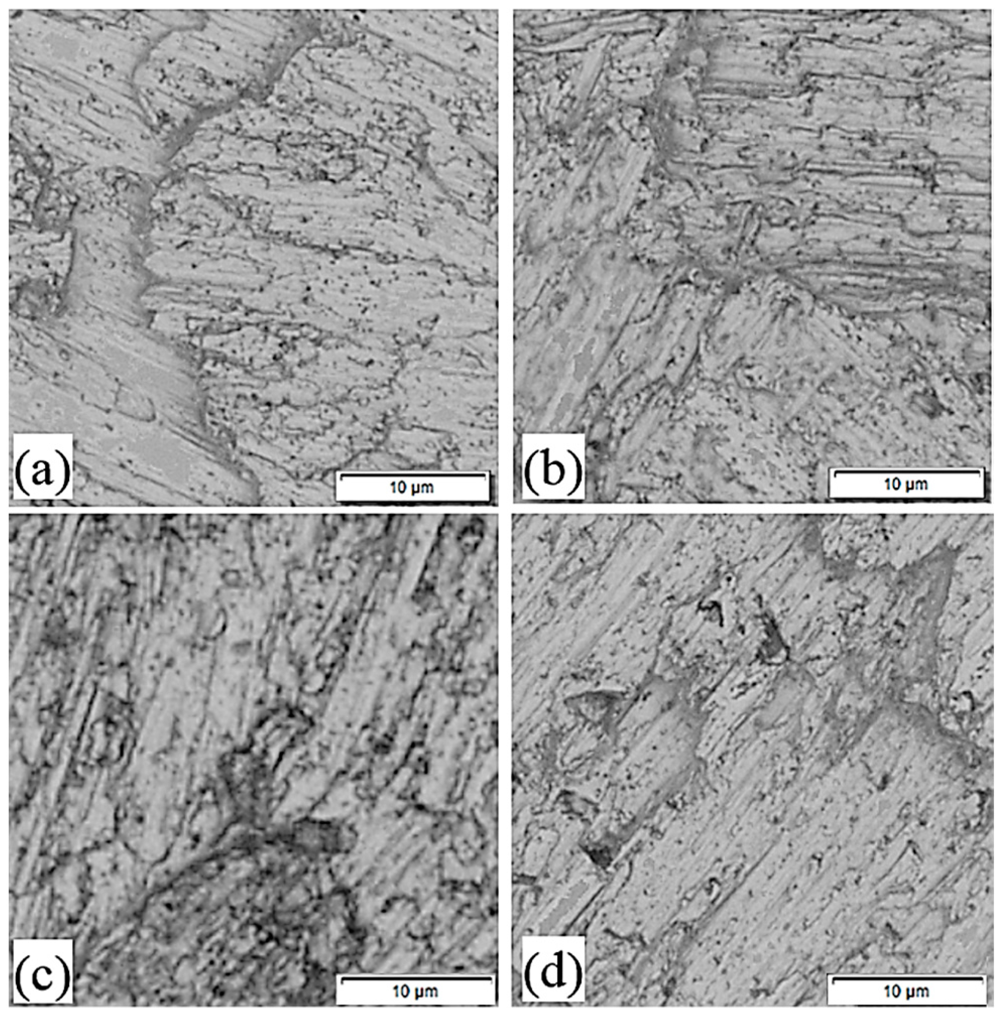
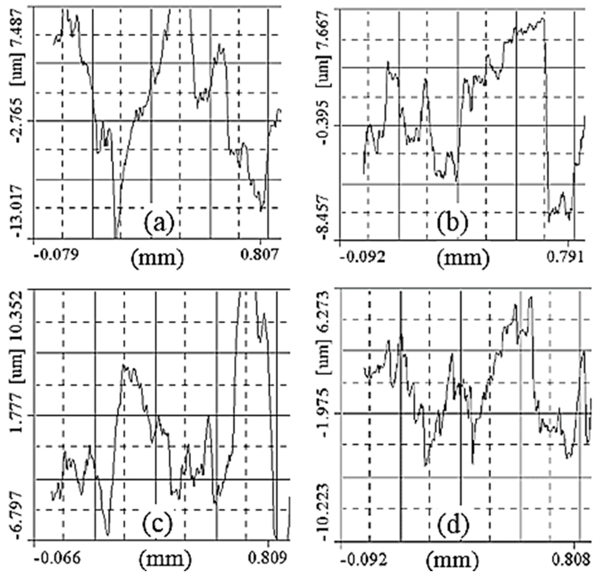
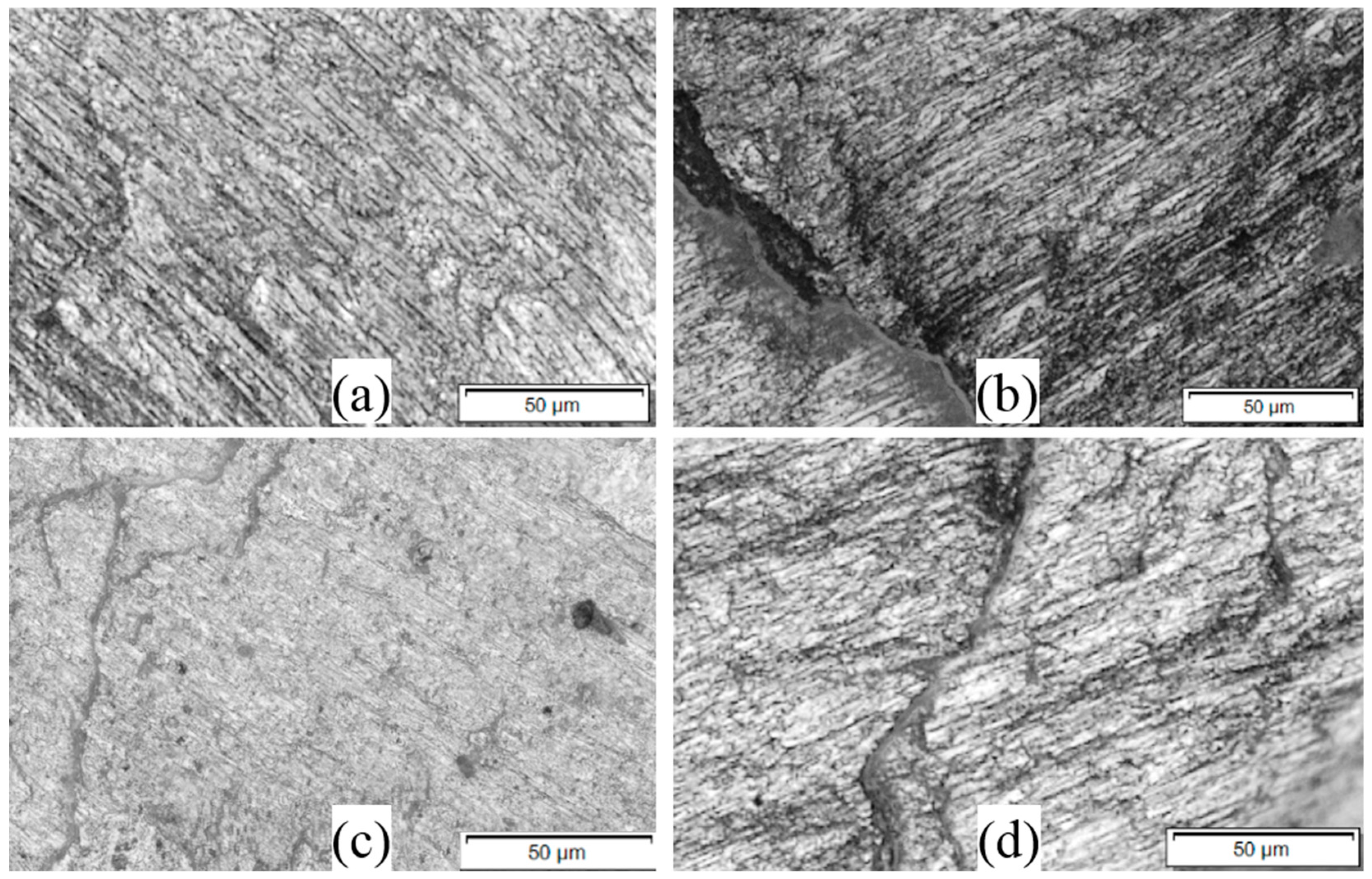
3.1. Machined Surfaces

The average surface roughness of nano-MMCs machined at different feeds and speeds is shown in Figure 1 with respect to machining speed and feed rate. The trend of surface roughness changes with the change of machining conditions. When the machining speed is slow (60 mm/min), the roughness also appears to be lower at smaller feed but it increases with the increase of feed. However, at faster machining speeds (100–140 mm/min), surface roughness is higher at lower feed and then it decreases slightly with the increase of feed. Finally, it remains almost constant with a further increase of feed. Figure 1 also demonstrates that the lowest surface roughness is achieved at the smallest feed (0.02 mm/tooth) and slowest speed (60 mm/min).
The machined surfaces consist of traces of nose edge profiles for cutting tools. The depth and extent of profile depend on the depth of cut and feed. However, material properties such as ductility, brittleness, and elasticity also distort the profile of tool nose edge compared to original shape. These also incorporate additional features such as brittle fracture and side flow on machined surfaces based on material properties. Machining speed and feed rate influence material properties in machining zone. Higher speed increases the strain rate and temperature. On the other hand, higher strain rate works to harden the materials while higher temperature softens it. The structure of materials itself plays an important role in determining hardening or softening effect. For a given length of cut, at the low feed, the distance between two successive tool paths is less and hence a higher number of tool–particle interactions will occur than at the higher feed [20]. However, as the particles are very small, surface damage due to tool-particle interactions is almost absent [23]. Therefore, surface roughness at the lower feed is smallest in case of nano-MMCs. At the higher speed and lower feed, thermal effect dominates, resulting in the increase in the ductility of MMCs. In addition, tensile ductility of nano-MMCs naturally increases with the incorporation of highly elastic nano-sized reinforcements to facilitate elastic recovery [23]. These contribute to higher surface roughness at the higher speed and lower feed. With the feed increase, temperatures decreases due to increased distance between two successive tool paths. This reduces the ductility and allows machined surfaces to replicate the tool path with slightly better surface finish.
The profiles of machined surfaces in different conditions are shown in Figure 2. The peaks and valleys of different magnitudes are clearly visible in all of the surfaces. The most regular and uniform peaks and valleys are noted at the slowest speed and lowest feed. In other cases, the peaks and valleys are irregular. The surface profiles cannot exhibit any effect of reinforcing particle explicitly. The surface profiles support the above-mentioned discussion as ductility and elastic recovery of nano-MMCs vary at different machining feeds and speeds.
The morphology of machined nano-MMC surfaces in different machining conditions is presented in Figure 3. The traces of cutting tools are clearly visible in all cases in addition to the material flow. The material flowed in a way that lobes and layers were generated. All the machined surfaces got pitting dots and various sizes of holes/craters. Extended lobes, smaller craters and fewer layers were noted on surfaces machined at the low speed and low feed (Figure 3a). Such phenomena suggested that the material had better ductile flow in this condition. With the increase of feed, traces of cutting tools were intersected as shown in Figure 3b. In this case, shorter lobes at different directions were evident. This demonstrated less ductile material behavior at the higher feed and lower speed. When the speed is high and feed is low, the machined surface contained bigger crates almost with no lobe, as shown in Figure 3c. This indicates brittle material behavior in such a machining condition. At the higher speed and feed, machined surface also contained lots of crates and minor lobes for material deformation (Figure 3d). In this case, the material is neither so ductile nor so brittle. Therefore the average surface roughness varies accordingly with the change of corresponding machining conditions.
The overlaps of milling tool path were observed on machined surfaces due to repeated cutting on machined surfaces by the cutting tool. During machining, a portion of material was pushed by the cutting edge and then elastically recovered to its original position after the tool pass instead of being removed plastically. Consequently, machined surfaces were cut repeatedly. The tensile ductility of nano-MMCs was improved because of highly elastic nano-sized reinforcements to facilitate elastic recovery [23]. During the machining of traditional MMCs with micro-size particles, void marks could be left on machined surfaces due to particle pull-out [26] and thus deteriorate the surface finish. However, particle pull-out and fracture were not noticed on machined nano-MMC surfaces. The lower surface roughness for nano-MMCs compared to that for MMCs with micro-size particles revealed a relatively good machinability of such materials [23].

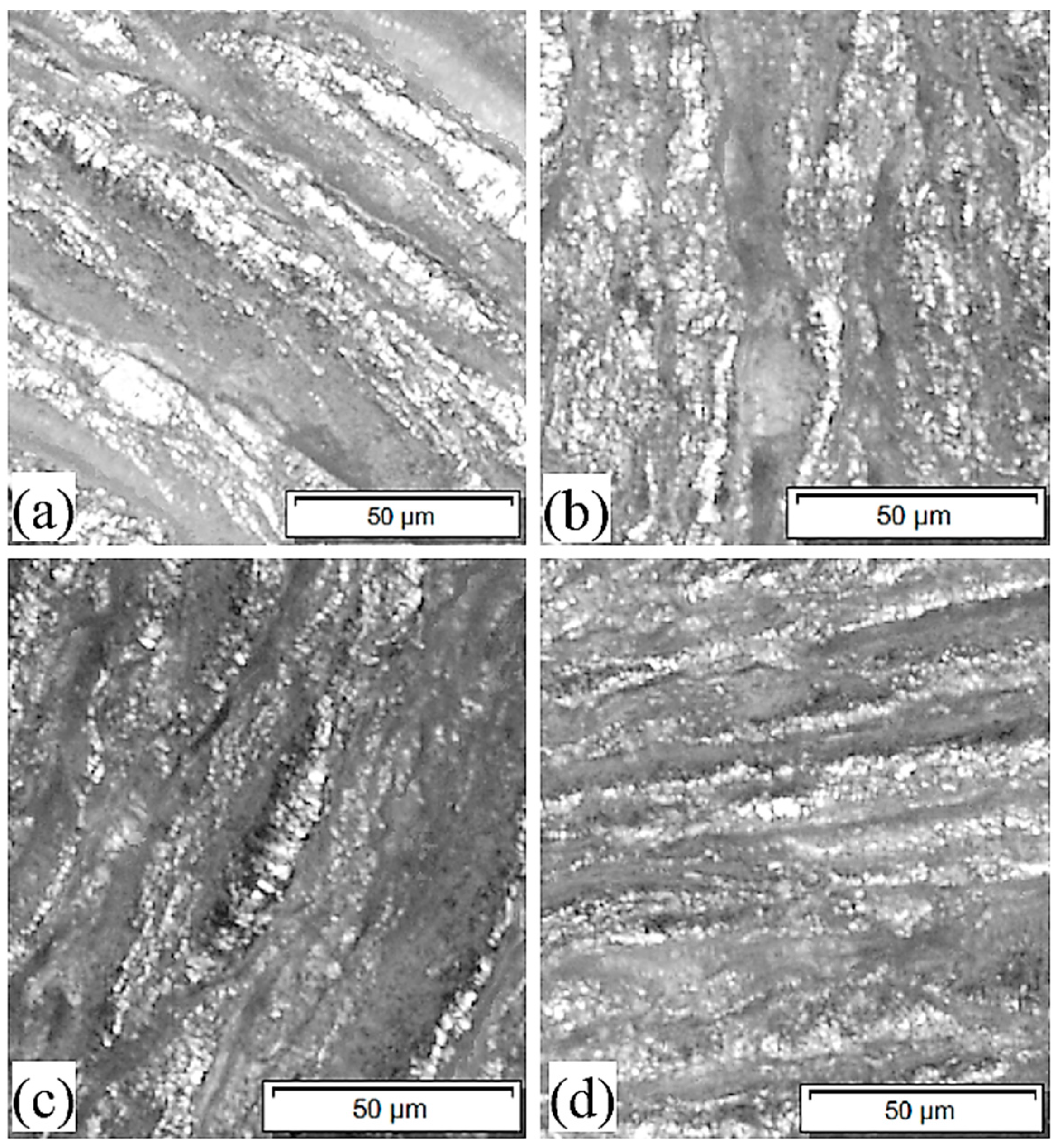
3.2. Machined Chips Morphology

The ratio of uncut chip thickness (feed/rev) to thickness of chips is known as chip thickness ratio or simply the chip ratio. This term gives information on chip formation and material deformation behavior in the machining zone during the material removal process. During metallic material milling, chips are formed along shear plane and they slide on the rake face of the cutting tool. The chip flow of metal is shorter and thicker than the metal prior to cutting because of plastic deformation at share plane/zone. Friction and/or adhesion with the rake face slow down the flow rate of upward chips compare to cutting speed. The smaller chip ratio indicates that the chips undergo more plastic deformation and vice versa. Figure 4 show the chip ratio of nano-MMCs after machining at different feeds and speeds. Chip ratio increases with the increase of feed or uncut chip thickness for all cutting speeds. Chip ratio at the lowest speed of 60 m/min is smaller than that at the higher speeds in the case of all feeds. Chip ratio increases with the increase of speed at 100 m/mm and then decreases again with the further increase of speed.
At a higher feed, the uncut chip thickness is larger. Sever plastic deformation in the chips takes place at tool-chip interfaces. However, the degree of plastic deformation decreases as the distance from tool-chip interface increases towards the top of chips. This causes relatively thin chips resulting in a higher chip ratio. As mentioned previously, machining speed contributes to material softening due to heat generation and material hardening by the induced strain rate. These two opposite effects are traded in at different levels based on material structures. When softening effect takes over, it is easy for the chips to slide over the tool rake face and elongate in the longitudinal direction instead of thickening. Therefore, the chips become relatively thinner and chip ratio is much higher. An opposite effect takes place when relative chip thickness increases due to strain hardening effect. It seems that, for nano-MMCs considered in this investigation, at lower speed, the strain hardening takes over the softening effect. However, with the increase of speed, the contribution of softening effect is more pronounced. With the further increase of speed, the contributions of the hardening effect become dominant and therefore the chip ratio varies accordingly.
The top surfaces of chips formed under different machining conditions are shown in Figure 5. It is evidently shown that the chips are full of wrinkles. These wrinkles are generated due to curly chips. Uneven strain across the plastic zone during the chip formation causes curly chips, which in turn depends on the ductility/brittleness of workpiece materials. Brittle materials generate chips will little or no curl contrary to ductile materials which shows the formation of long spiral chips with wrinkles [26]. Therefore, nano-MMCs retain most of the ductility of matrix materials due to nano-sized reinforcements.
Figure 6 shows the bottom surfaces of the chips at different machining conditions. Apparently, bottom surfaces of chips got quite thicker layers of deformed materials (Figure 6b,d) due to their material flow at the higher feed irrespective of speed. The surfaces machined at lower feed show thin layers of deformed materials. Though the chip surfaces are very similar at both higher and lower speeds (Figure 6c,d), a close look reveals that the surface generated at higher milling speed is smoother owing to thermal softening of materials at the higher speed. It seems that at a lower feed the extended friction is more dominant and at higher feed both adhesion and material flow occur at tool-chip interface. Therefore, the chip ratio is altered accordingly.

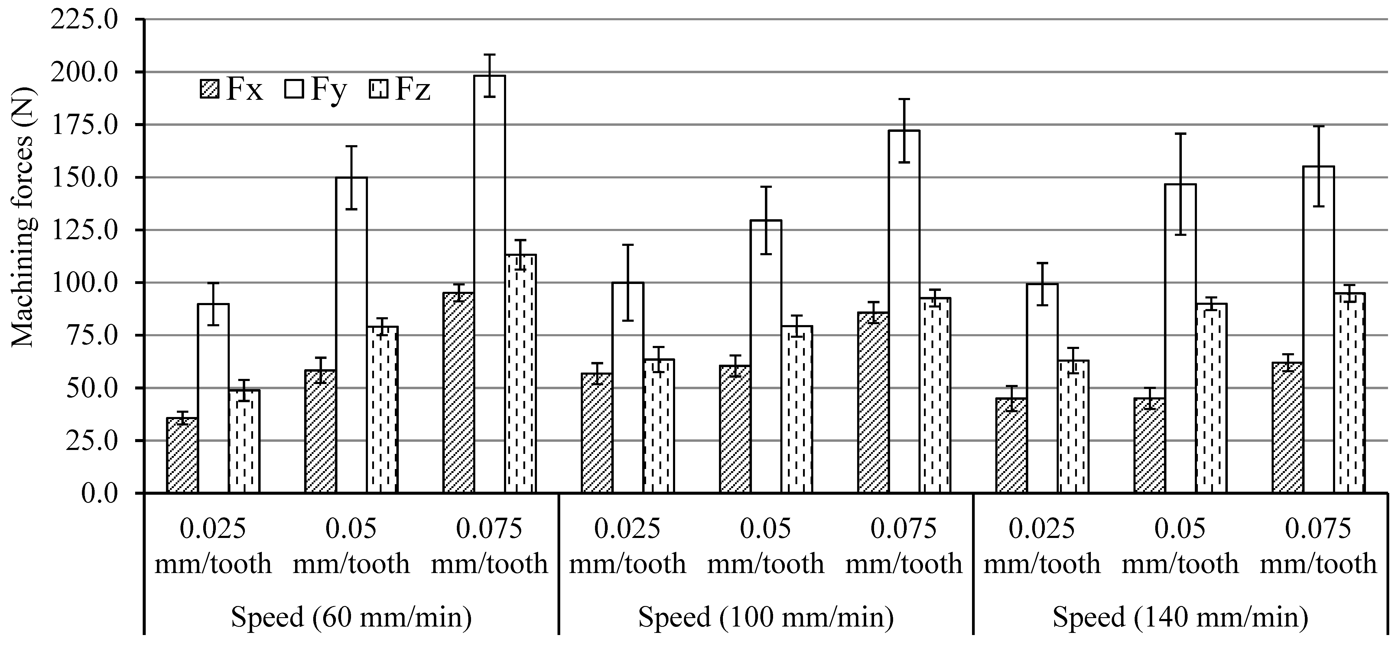
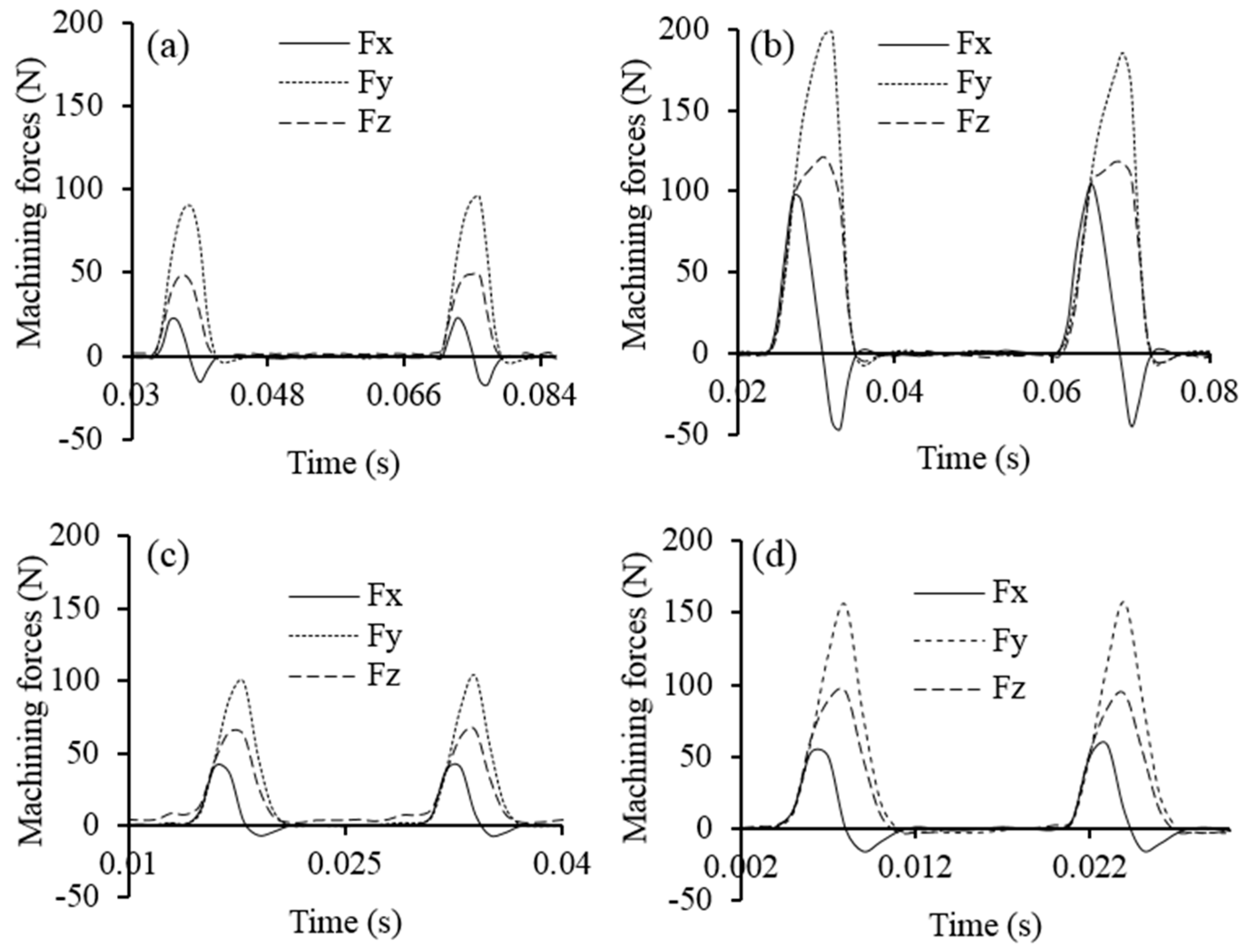
3.3. Machining Forces

The machining forces at radial (Fx), cutting/tangential (Fy) and thrust directions during the milling of nano-MMCs are shown in Figure 7. Highest force was measured in the cutting direction, smallest force was measured in radial direction and thrust force was in between them. These trends did not change with the variation of machining conditions. At all speeds, all the forces increased with the increase of feed since more materials were removed at the higher feed. The variation of forces with the speed change was not significant at 0.025 and 0.05 mm/tooth feed and minor variations did not follow any trend. However, the forces decreased with the increase of speed at 0.075 mm/tooth feed. It appears that at lower feeds, contribution of softening effect of the speed is not significant to reduce machining forces. However, the softening of materials due to the thermal effect takes place with the increase of speed at the high feed rate. The signals of forces at different machining conditions are presented in Figure 8. It showed that in all cases the forces started to increase as the tool cutting edge engaged to remove materials. After that initial engage, the forces were maximized when the maximum material thickness was cut and finally decreased as the cut thickness was reduced to the minimum level. At the end of cutting cycle, the cutting tool was pulled towards the workpiece just before the disengagement. This gives a portion of negative forces in the cutting cycles in order to achieve the maximum quantity for radial force (Fx).

4. Conclusions

The present investigation explored the behavior of SiC nanoparticles reinforced with Al-based MMCs under different milling conditions. The following conclusions can be drawn based on the results presented:
  • Under different milling conditions, the surface generated on nano-MMCs is similar to that of monolithic materials due to the absence of particle fracture and pull-out related damage. Surface defects, such as lobes and layers, were minimum and the average surface roughness increased with the increase of feed at the lower speed. The effect of feed was negligible at higher speeds.
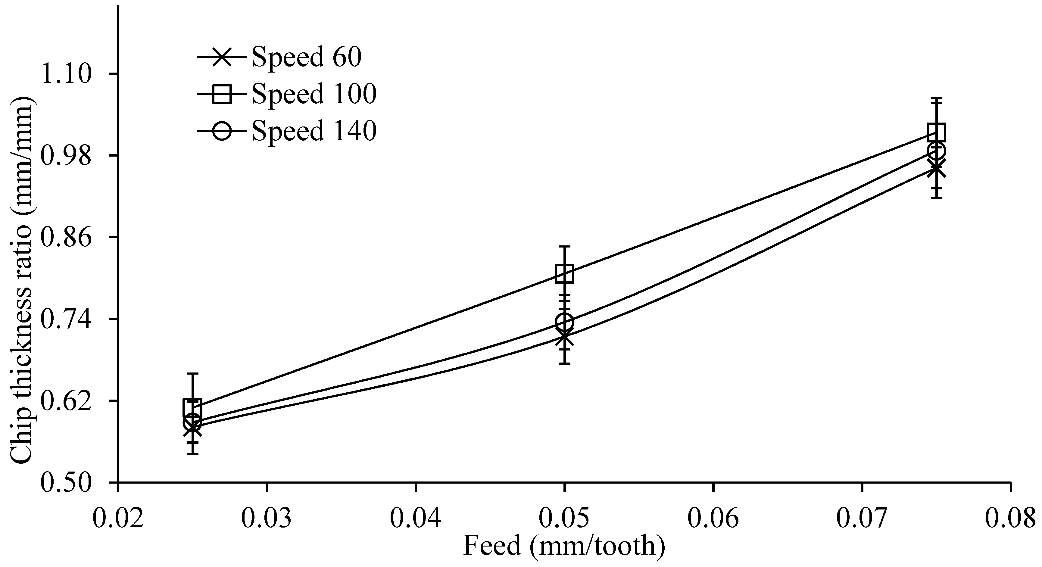
  • The chip ratio was higher at the higher feed for all cutting speeds. Wrinkles were noted on the top surface of the chips due to curly shape. At lower feed, the friction is more dominant in contrast to higher feed scenario where both adhesion and materials flow contribute to the chip formation.
  • Machining forces increase with the increase of feed at all speeds with the increase of material removal rate. The influence of machining speed on the forces was insignificant without following any trend. These behaviors could be attributed to the combined effects of thermal softening and strain hardening of machined materials in different machining conditions.

Author Contributions

Alokesh Pramanik and Animesh Basak designed and performed the experiments; Yu Dong, Subramaniam Shankar and Guy Littlefair contributed reagents/materials/analysis tools and write the paper.

Conflicts of Interest

The authors declare no conflict of interest.

References

  1. Basak, A.; Pramanik, A.; Islam, M.N. Failure mechanisms of nanoparticle reinforced metal matrix composite. Adv. Mater. Res. 2013, 774–776, 548–551. [Google Scholar] [CrossRef]
  2. Basak, A.; Pramanik, A.; Islam, M.N.; Anandakrishnan, V. Challenges and recent developments on nanoparticle-reinforced metal matrix composites. Fill. Reinf. Adv. Nanocompos. 2015, 14, 349–367. [Google Scholar] [CrossRef]
  3. Basumallick, A.; Sarkar, J.; Das, G.; Mukherjee, S. On the Synthesis of In Situ Ni–SiO2 Nanocomposites by Isothermal and Non Isothermal Reduction Technique. Mater. Manuf. Process. 2006, 21, 648–651. [Google Scholar] [CrossRef]
  4. Ferkel, H.; Mordike, B. Magnesium strengthened by SiC nanoparticles. Mater. Sci. Eng. A 2001, 298, 193–199. [Google Scholar] [CrossRef]
  5. Hassan, S.; Gupta, M. Development of high performance magnesium nano-composites using nano-Al2O3 as reinforcement. Mater. Sci. Eng. A 2005, 392, 163–168. [Google Scholar] [CrossRef]
  6. Huda, D.; El Baradie, M.A.; Hashmi, M.S.J. Analytical study for the stress analysis of Metal Matrix Composites. J. Mater. Process. Technol. 1994, 45, 429–434. [Google Scholar] [CrossRef]
  7. Kang, Y.-C.; Chan, S.L.-I. Tensile properties of nanometric Al2O3 particulate-reinforced aluminum matrix composites. Mater. Chem. Phys. 2004, 85, 438–443. [Google Scholar] [CrossRef]
  8. Li, J.; Liu, J.; Liu, J.; Ji, Y.; Xu, C. Experimental investigation on the machinability of SiC nano-particles reinforced magnesium nanocomposites during micro-milling processes. Int. J. Manuf. Res. 2013, 8, 64–84. [Google Scholar] [CrossRef]
  9. Liu, J.; Li, J.; Ji, Y.; Xu, C. Investigation on the effect of SiC nanoparticles on cutting forces for micro-milling magnesium matrix composites. In Proceedings of the ASME 2011 International Manufacturing Science and Engineering Conference, Corvallis, OR, USA, 13–17 June 2011. [Google Scholar]
  10. Lü, L.; Lai, M.; Liang, W. Magnesium nanocomposite via mechanochemical milling. Compos. Sci. Technol. 2004, 64, 2009–2014. [Google Scholar] [CrossRef]
  11. Ma, Z.; Li, Y.; Liang, Y.; Zheng, F.; Bi, J.; Tjong, S. Nanometric Si3N4 particulate-reinforced aluminum composite. Mater. Sci. Eng. A 1996, 219, 229–231. [Google Scholar] [CrossRef]
  12. Miracle, D. Metal matrix composites–from science to technological significance. Compos. Sci. Technol. 2005, 65, 2526–2540. [Google Scholar] [CrossRef]
  13. Paramsothy, M.; Chan, J.; Kwok, R.; Gupta, M. Al2O3 nanoparticle addition to commercial magnesium alloys: Multiple beneficial effects. Nanomaterials 2012, 2, 147–162. [Google Scholar] [CrossRef] [PubMed]
  14. Pramanik, A.; Arsecularatne, J.; Zhang, L. Machining of particulate-reinforced metal matrix composites. In Machining; Springer: New York, NY, USA, 2008; pp. 127–166. [Google Scholar]
  15. Pramanik, A.; Basak, A.K. Fracture and fatigue life of Al-based MMCs machined at different conditions. Eng. Fract. Mech. 2018, 191, 33–45. [Google Scholar] [CrossRef]
  16. Pramanik, A.; Basak, A.K. Effect of machining parameters on deformation behaviour of Al-based metal matrix composites under tension. Proc. Inst. Mech. Eng. B J. Eng. Manuf. 2018, 232, 217–225. [Google Scholar] [CrossRef]
  17. Pramanik, A.; Littlefair, G. Fabrication of nano-particle reinforced metal matrix composites. Adv. Mater. Res. 2013, 651, 289–294. [Google Scholar] [CrossRef]
  18. Pramanik, A.; Zhang, L.; Arsecularatne, J. Micro-indentation of metal matrix composites—An FEM analysis. Key Eng. Mater. 2007, 340–341, 563–570. [Google Scholar] [CrossRef]
  19. Pramanik, A.; Zhang, L.; Arsecularatne, J. Machining of metal matrix composites: Effect of ceramic particles on residual stress, surface roughness and chip formation. Int. J. Mach. Tools Manuf. 2008, 48, 1613–1625. [Google Scholar] [CrossRef]
  20. Pramanik, A.; Zhang, L.C.; Arsecularatne, J.A. Deformation mechanisms of MMCs under indentation. Compos. Sci. Technol. 2008, 68, 1304–1312. [Google Scholar] [CrossRef]
  21. Teng, X.; Huo, D.; Wong, E.; Meenashisundaram, G.; Gupta, M. Micro-machinability of nanoparticle-reinforced Mg-based MMCs: An experimental investigation. Int. J. Adv. Manuf. Technol. 2016, 87, 2165–2178. [Google Scholar] [CrossRef]
  22. Teng, X.; Huo, D.; Wong, W.L.E.; Sankaranarayanan, S.; Gupta, M. Machinability Investigation in Micro-milling of Mg Based MMCs with Nano-Sized Particles. In Magnesium Technology; Springer: New York, NY, USA, 2017; pp. 61–69. [Google Scholar]
  23. Tjong, S.C.; Ma, Z. Microstructural and mechanical characteristics of in situ metal matrix composites. Mater. Sci. Eng. R Rep. 2000, 29, 49–113. [Google Scholar] [CrossRef]
  24. Wang, Z.; Chen, T.K.; Lloyd, D.J. Stress distribution in particulate-reinforced metal-matrix composites subjected to external load. Metall. Trans. A 1993, 24, 197–207. [Google Scholar] [CrossRef]
  25. Xiaochun, L.; Yang, Y.; Weiss, D. Theoretical and experimental study on ultrasonic dispersion of nanoparticles for strengthening cast Aluminum Alloy A356. Metall. Sci. Technol. 2013, 26, 12–20. [Google Scholar]
  26. Zhang, Z.; Zhang, L.; Mai, Y.W. Modeling steady wear of steel/Al2O3-Al particle reinforced composite system. Wear 1997, 211, 147–150. [Google Scholar] [CrossRef]
Figure 1. Effect of feed and speed during milling of nanoparticle reinforced MMCs.
Jcs 02 00013 g001
Figure 2. Surface profile of machined surface at: (a) 60 mm/min speed, 0.025 mm/tooth feed; (b) 60 mm/min speed, 0.075 mm/tooth feed; (c) 140 mm/min speed, 0.025 mm/tooth feed and (d) 140 mm/min speed, 0.075 mm/tooth feed.
Jcs 02 00013 g002
Figure 3. Morphology of the machined surfaces in different conditions: (a) 60 mm/min speed, feed 0.025 mm/tooth; (b) 60 mm/min speed, 0.075 mm/tooth feed; (c) 140 mm/min speed, 0.025 mm/tooth feed and (d) 140 mm/min speed, 0.075 mm/tooth feed.
Jcs 02 00013 g003
Figure 4. Chip thickness ratio of nanoparticles reinforced with Al-based metal matrix composites (nano-MMCs) at different feeds and speeds.
Jcs 02 00013 g004
Figure 5. Top surfaces of chips in different conditions: (a) 60 mm/min speed, 0.025 mm/tooth feed; (b) 60 mm/min speed, 0.075 mm/tooth feed; (c) 140 mm/min speed, 0.025 mm/tooth feed and (d) 140 mm/min speed, 0.075 mm/tooth feed.
Jcs 02 00013 g005
Figure 6. Bottom surfaces of chips in different conditions (a) 60 mm/min speed, 0.025 mm/tooth feed; (b) 60 mm/min speed, 0.075 mm/tooth feed; (c) 140 mm/min speed, 0.025 mm/tooth feed and (d) 140 mm/min speed, 0.075 mm/tooth feed.
Jcs 02 00013 g006
Figure 7. Machining forces in different conditions.
Jcs 02 00013 g007
Figure 8. Force signals in different conditions: (a) 60 mm/min speed, 0.025 mm/tooth feed; (b) 60 mm/min speed, 0.075 mm/tooth feed; (c) 140 mm/min speed, 0.025 mm/tooth feed and (d) 140 mm/min speed, 0.075 mm/tooth feed.
Jcs 02 00013 g008
Table 1. Parameter variations in milling metal matrix composites (MMCs) reinforced with SiC particles.
Particle Size (nm)700
Speed (m/min)60100140
Feed (mm/tooth)0.0250.00.075
Table 2. Details of design of experiments.
Experiment No.Cutting Speed (mm/min)Feed Rate (mm/tooth)
1600.025
2600.05
3600.075
41000.025
51000.05
61000.075
71400.025
81400.05
91400.075

