1. Introduction
There are many books, review articles and papers that are dedicated to the investigation of the behavior of cracked solids and composites that are subjected to mechanical loadings. Relatively few papers appeared concerning the induced thermal stresses caused by the application of heat flow in the presence of cracks and other types of damage. Quantifying these stresses in the presence of defects is important as they may give information about the locations of high stress concentrations, which can cause failure. It should be mentioned that in the framework of these problems, the temperature field distribution is not constant, but rather spatially dependent, which should be determined according to the considered boundary-value problem. The resulting heat flux caused by the application of heat flow in a cracked homogeneous material is singular at the crack front, and the temperature is continuous along the crack line and discontinuous across the crack (insulated crack).
Due to the one-way thermomechanical coupling, the temperature field induces thermal stresses in the material, which are singular near the crack tip. Examples of some articles in which the effect of heat flow in cracked materials is investigated are: [
1,
2,
3,
4,
5,
6,
7,
8,
9,
10,
11] and the references cited therein, as well as Chapter 10 in the monograph [
12]. The analysis of [
13] of the singularities at the tip of interfacial cracks in anisotropic materials subjected to heat flow forms a generalization of the square root singularity that occurs in homogeneous materials. A recent article in which the extended finite element method has been employed for the simulation of the heat flux and thermal stresses in cracked solids has been presented by [
14].
The aforementioned investigations are concerned with cracks in homogeneous materials or interfacial cracks between two homogeneous materials. When the effect of thermal loading on composite materials with cracks is sought, the application of these analyses necessitates the homogenization of the considered multiphase material. As a result of this homogenization, the effect of the composite’s periodic microstructure is lost. Furthermore, when the homogenization technique is employed in the analysis of a cracked composite with a periodic microstructure, a repeating unit cell that represents the entire composite is considered. The introduction of a crack in the repeating unit cell implies its repeated existence in the entire composite, which obviously is not a realistic situation.
In the present investigation, a multiscale analysis is proposed for the establishment of the full thermoelastic field caused by the application of remote heat flow on cracked composite materials while taking into account their microstructure distributions. As a result of the application of thermal loading, the temperature and heat flux distributions are established by solving the steady state heat equation. The one-way coupling with the mechanical equations induces thermal stresses in the composite, which are subsequently determined by solving these equations.
The proposed method of solution consists of a micromechanical analysis, which is followed by a macromechanical one. In the most general case of a composite subjected to remote thermomechanical loading, the micromechanical analysis provides the effective thermal conductivities, elastic moduli and coefficients of thermal expansion of the undamaged composite. This is carried out by utilizing the high-fidelity generalized method of cells (HFGMC), which has been fully described in [
15]. In the framework of the macromechanical analysis, the representative cell method [
16] is employed. According to this method, the composite domain is divided into several rectangular cells with respect to which the governing and constitutive equations are formulated. This is followed by the application of the discrete Fourier transform, which reduces the multiple cell problem to the analysis of a single cell in the transform domain. The transformed temperature and displacement vector are expanded into a second-order polynomial, and the heat and equilibrium equations, as well as the interfacial and boundary conditions are imposed in the average (integral) sense. A discretization of the single cell problem provides the solution in the form of a system of algebraic equations; see [
15]. The inversion of the Fourier transform provides the actual thermal and mechanical fields at the various cells and, thus, at every desired point of the composite. The effect of crack existence is taken into account by the continuum damage mechanics considerations combined with the localized damage analysis as described by [
17,
18]. It should be noted that in both of these articles, the constant temperature has been uniformly prescribed in the entire composite.
The proposed approach is verified by comparing its prediction with exact solutions for a crack embedded in homogeneous materials that are subjected to remote heat flow. The temperature field, heat flux and the resulting induced stress distributions are shown and discussed in the cases of fiber-reinforced polymer matrix composite, porous ceramic material and periodically-layered ceramic composite, all of which are subjected to heat flow.
The present article is organized as follows. In
Section 2, the constitutive and governing equations are presented. This is followed in
Section 3 by the method of solution, which is presented in the real space followed by its formulation in the Fourier transform domain. The solution in the latter domain utilizes the methods presented in [
15]. The inversion of the Fourier transform provides the actual solution, which requires iterations for convergence. In
Section 4, verifications of the proposed method are presented by comparison with exact solutions.
Section 5 provides the results of the application of the proposed method on three types of composites. Finally, the Conclusion section is given for a summary and future generalizations.
2. Constitutive and Governing Equations
Consider a thermoelastic homogeneous orthotropic material. The constitutive equations are given as follows:
where
,
,
and
are the stress, strain, stiffness and thermal stress tensors, respectively. In this equation,
T is the temperature field deviation from a reference temperature. The thermal flux vector
is related to the temperature gradient via Fourier’s law in the form:
and
is the thermal conductivity tensor.
The governing equations are given by:
and:
It should be noted that the temperature field is uncoupled to the mechanical field, but it affects the latter through the constitutive Equation (
1) (one-way thermomechanical coupling).
As discussed in [
17], the effect of the crack can be represented, in the framework of the continuum damage mechanics, by introducing a damage parameter D, which takes the value of zero or one. In the crack region, D = 1, whereas D = 0 otherwise. As a result, Equations (
1) and (
2) are reduced to the following form:
and:
As discussed in the next section, Equations (
5) and (
6) are more conveniently represented as follows:
where:
which play the role of eigen stress and eigen heat flux, respectively. Consequently, the damage parameter D = 1 in the crack region results in traction-free and insulated crack surfaces. It should be noted that D = 1 in the crack region implies that the crack does not evolve. The proposed method enables however the crack progression; see [
17].
3. Method of Solution
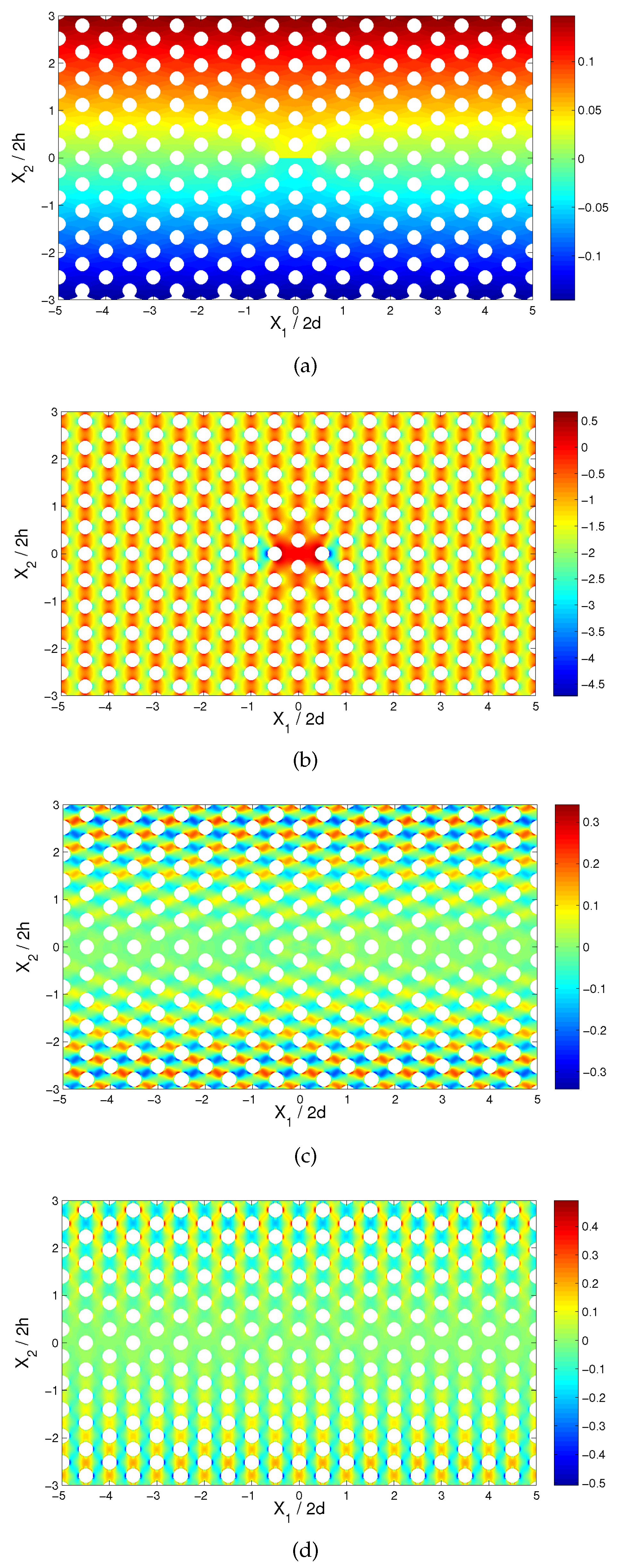
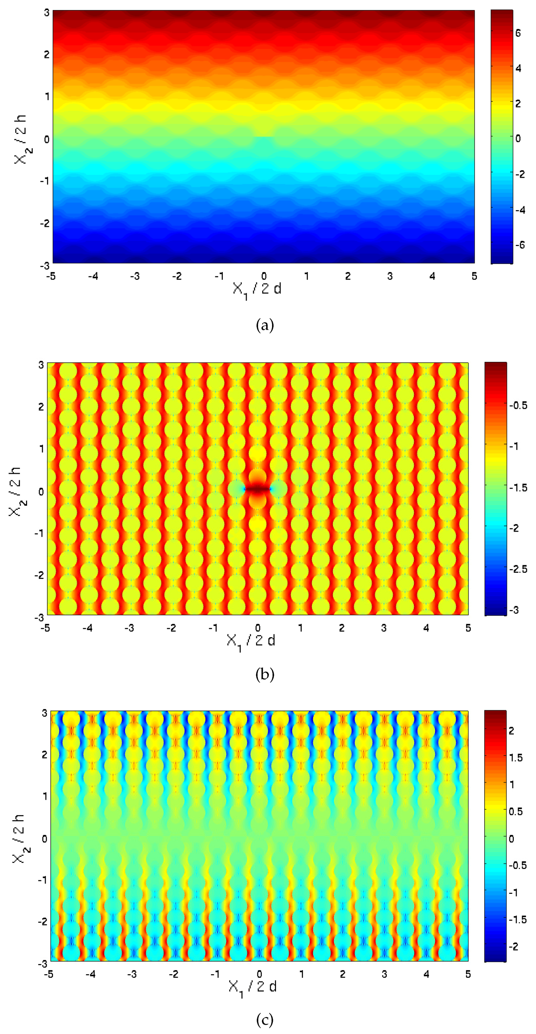
Consider a composite material with a doubly-periodic microstructure. As an illustration,
Figure 1a shows a composite with a hexagonal array of fibers embedded in the matrix. Also shown is a crack of length 2a, which connects two adjacent fibers. The composite is subjected to a heat flux
(
Figure 1a is shown with
). As a result of the crack existence, the periodicity of the composite is lost, and consequently, a repeating unit cell (a representative volume element) does not exist. In the following, we present a method of solution that is based on the representative cell method [
16], which is capable of establishing the full temperature and thermoelastic fields. To this end, let us consider a rectangular domain
,
of the composite, which includes the crack region. It is assumed that this rectangular domain, which is subjected to the heat flux
, is sufficiently extensive such that the temperature and thermoelastic fields at its boundaries are not influenced by the crack existence. It should be mentioned that as long as the rectangular domain is sufficiently extensive, the distribution of the fibers and the location of the crack is arbitrary. It is advisable however to preserve symmetry (as illustrated by the insets of the figures that are discussed in the following) in order to obtain symmetrical field distributions. Consequently, the boundary conditions (presently, the heat flux) that are applied on
and
can be referred to as the far-field boundary conditions. This region is divided into
cells; see
Figure 1b for
. Every cell is labeled by
with
and
. In each cell, local coordinates
are introduced whose origins are located at its center; see
Figure 1c.
3.1. Formulation in the Real Domain
The constitutive Equation (
7) in cell
can be written as:
If the crack exists in the cell
only, it follows that
takes the form:
where
is the Kronecker delta. It is obvious that this last expression can be generalized for the modeling of cracks that exist in other cells (as long as it is ensured that the size of the rectangular region is sufficiently large such that the far-field at its boundaries is not affected by the cracks’ existence).
Similarly, constitutive Equation (
8) in the cell
can be written as:
where:
The governing Equations (
3) and (
4) of the materials within the cell
take the form:
Next, the continuity of displacements
and temperature
between adjacent cells must be imposed. These imply that (the square brackets do not denote quantity jumps):
and:
Similarly, the continuity of tractions
and the normal components of the heat flux
between adjacent cells are fulfilled by requiring that:
and
Finally, the boundary conditions have to be imposed on the boundaries
and
of the rectangle, which as stated before, must be sufficiently far away such that the effect of the crack is negligible. The tractions and the normal components of the heat flux on opposite sufficiently remote sides of this rectangle must be equal. Thus:
and:
On the other hand, the displacements and temperature at these opposite sides differ. Their differences (jumps) are defined by:
and:
These jumps are given by the far-field (which is not affected by the crack existence) as follows:
where
and
are the average (far-field) strain of the unperturbed periodic composite. They can be determined from the micromechanically-established macroscopic (average) constitutive law:
where
and
are the effective stiffness and thermal stress tensors of the periodic (unperturbed) composite which can be determined by HFGMC micromechanical analysis [
15], and
are the far-field applied tractions. When the composite is subjected to a heat flux only (i.e., in the absence of a strain loading), the average (far-field) strains
are equal to zero.
Similarly,
where
and
are the components of the remote temperature gradient. They can be determined from the micromechanically-established macroscopic (average) Fourier law of the composite:
with
being the effective thermal conductivity tensor that can be determined from HFGMC analysis [
19], and
is the far-field applied heat flux.
3.2. Formulation in the Transform Domain
The next stage in the representative cell method consists of the application of the double discrete Fourier transform. For the displacement vector
(for example), this transform is defined by:
where:
The application of this transform to the boundary problem (
11)–(
32) for the rectangular domain
,
, which is divided into
cells, converts it to the problem for the single representative cell
,
with respect to the complex valued transforms. The resulting constitutive Equations (
11)–(
14) take the form:
The governing Equations (
15)–(
16) reduce to:
Next, the continuity conditions (
17)–(
28) in the transform domain are:
In all of these equations, ; .
As for the displacements and temperature differences (jumps) that are given by (
29)–(
32), they appear in the transform domain as follows:
The set of Equations (
38)–(
55) defines a boundary value problem in the transform domain. These equations can be solved by the methods that have been presented in detail in Chapter 11 of [
15] for functionally-graded materials. Thus, the representative cell domain
,
is divided into several rectangular sub-cells,
,
; see
Figure 1c. The transformed displacement vector and temperature are expanded into second-order polynomials, and the equilibrium and heat equations, interfacial and boundary conditions are imposed in the average (integral) sense. This results in a system of algebraic equations, the solution of which provides the transformed thermal and mechanical fields. The actual fields at any point within the cells
of the considered rectangular region
,
can be determined by the application of the inverse transform, which for the displacement vector (for example) is given by:
In the application of this solution, the eigenfield vectors
and
to be employed in Equations (
38) and (
40) are not known. Hence, an iterative solution has to be employed as follows.
Start by assuming that and , and solve the above equations in the transform domain.
Apply the inverse transform formula to compute the thermal and stress fields. The field variables in the actual space can be employed to compute the current eigenfields and .
Compute the transforms of
and
, (
39) and (
41), to be employed in Equations (
38) and (
40).
Solve again the equations in the transform domain. This procedure should be continued until the convergence to a desired degree of accuracy is achieved.
The computational efficiency of the present approach can be illustrated by considering the analysis of the cracked fiber-reinforced material with the fibers forming a hexagonal array, which will be discussed in the following. This composite region has been divided into cells (i.e., ). It should be noted that it is not possible to estimate in advance the size of the model (which is determined by the values of and ). In practice, the size of the model is determined by the requirement that the far-field is not affected by the local damage.
The representative cell has been divided in the framework of the higher-order theory into and sub-cells (which has been found to provide accurate results). The higher-order analysis requires the solution of 16 unknowns in each sub-cell (i.e., 32 unknowns in the complex transform domain). Hence, this discretization requires for each combination of , , the solution of a sparse system of 179,200 algebraic equations. A direct numerical solution (e.g., by a finite element procedure) with the same number of degrees of freedom would require solving a system of equations, which is very large. Another significant advantage of the present analysis over a direct computational approach stems from the fact that by increasing the size of the rectangular region , (in order to further diminish the crack effect) within which the computations in the transform domain are carried out (i.e., by increasing and ), the number of algebraic equations (179,200 in the discussed example) does not change. It should be noted however that the computer running time increases with the increase of and .
4. Verifications
In [
7], an exact solution for the temperature and thermal stresses fields is given for a crack of length
embedded within an infinite homogeneous anisotropic material. The material is subjected to a remote heat flux
, and the crack is traction-free and insulated such that its surface heat flux is equal to zero. With the effective heat conductivity, stiffness and thermal stress tensors,
,
and
, that characterize the considered homogenized anisotropic material, the solution of [
7] can be implemented to verify the field variation as predicted by the present analysis. The exact expressions for the temperature and heat flux are given by:
where:
and
with
.
In addition, the thermal stresses in the cracked material can be determined from the following expression:
In these equations,
,
and
are the three roots with the positive imaginary part of a cubic equation that is given together with
and
in [
7].
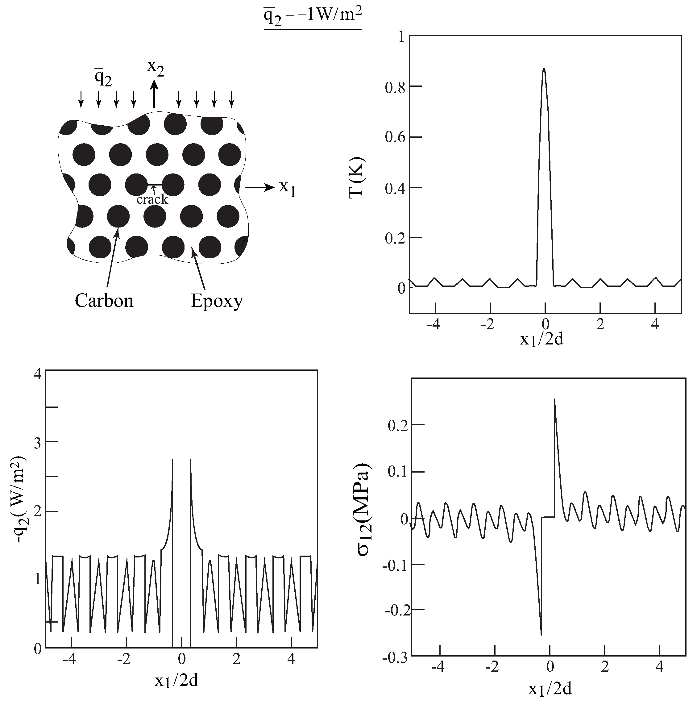
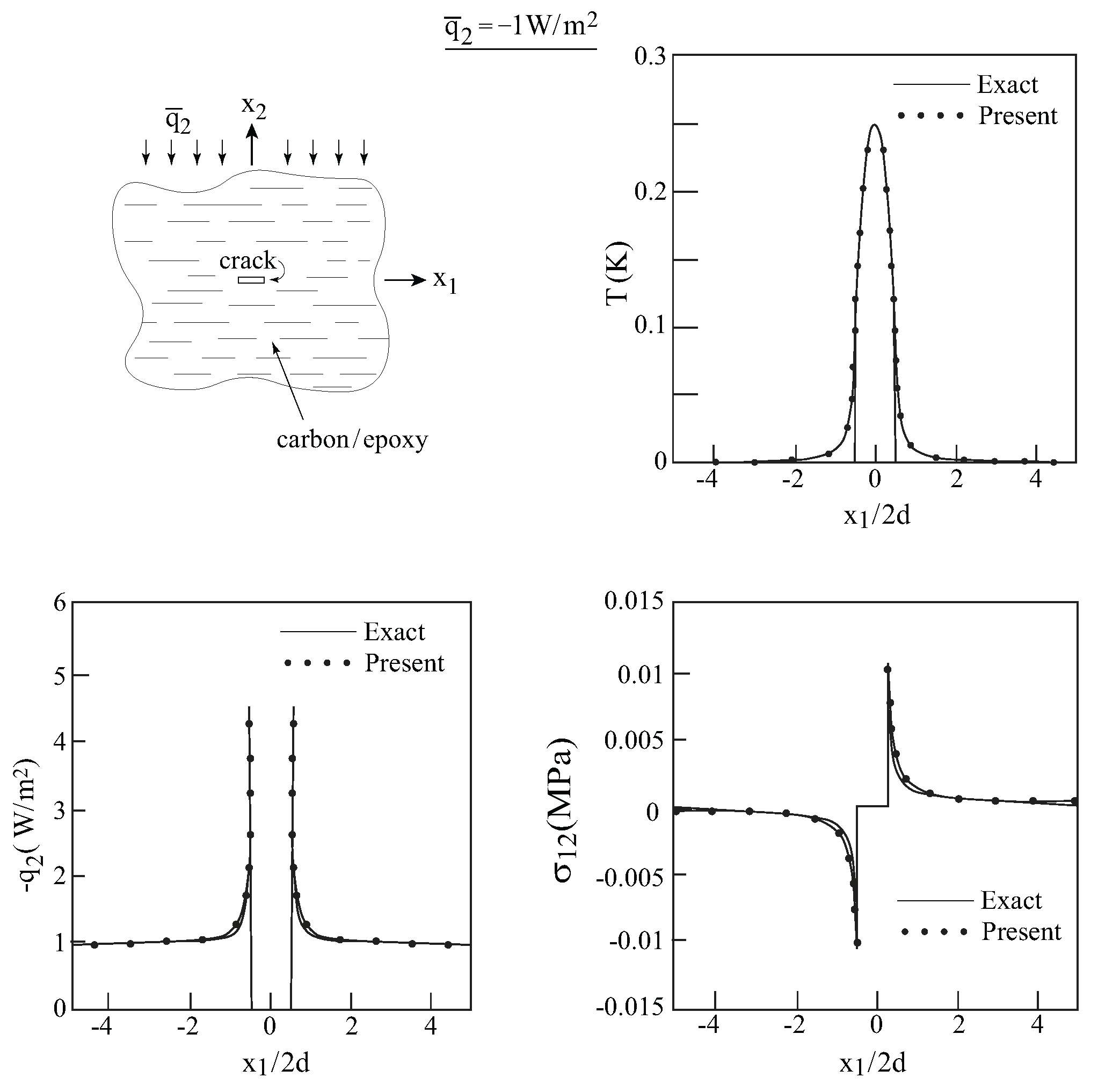
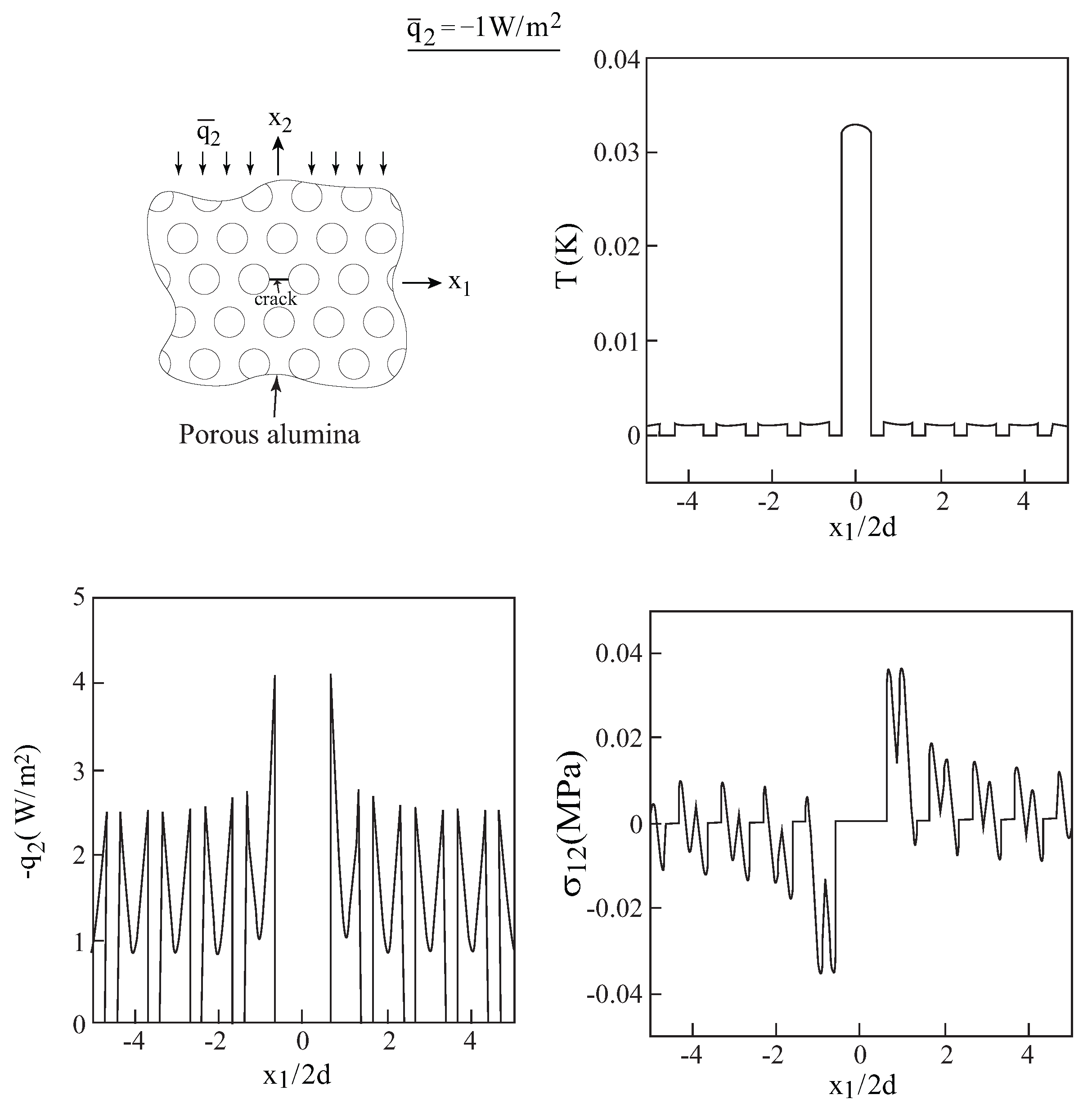
Consider a unidirectional fiber-reinforced composites that consists of carbon T300 fibers reinforcing an epoxy matrix. The volume fraction of the reinforcing fibers is
. The properties of the constituents, as well as the effective properties of the homogenized unidirectional composite, predicted by the HFGMC micromechanical model, are given in
Table 1. Let the axial direction of this homogenized composite be oriented in the one-direction, and a crack of length 2a/(2d) = 1 is introduced along this direction; see inset in
Figure 2. The homogenized composite is subjected to a remote heat flux
= −1 W/m
in the two-direction.
Figure 2 shows a comparison between the temperature, heat flux and the induced shear stress along the crack line as predicted by the exact solution of [
7] and the present approach. Very good agreement can be observed. It should be noted that only shear stress
exists along the crack line, whereas
along this line. This is in agreement with the result of [
20] who showed that in a cracked isotropic material that is subjected to a remote heat flux, only Mode II deformation exists.
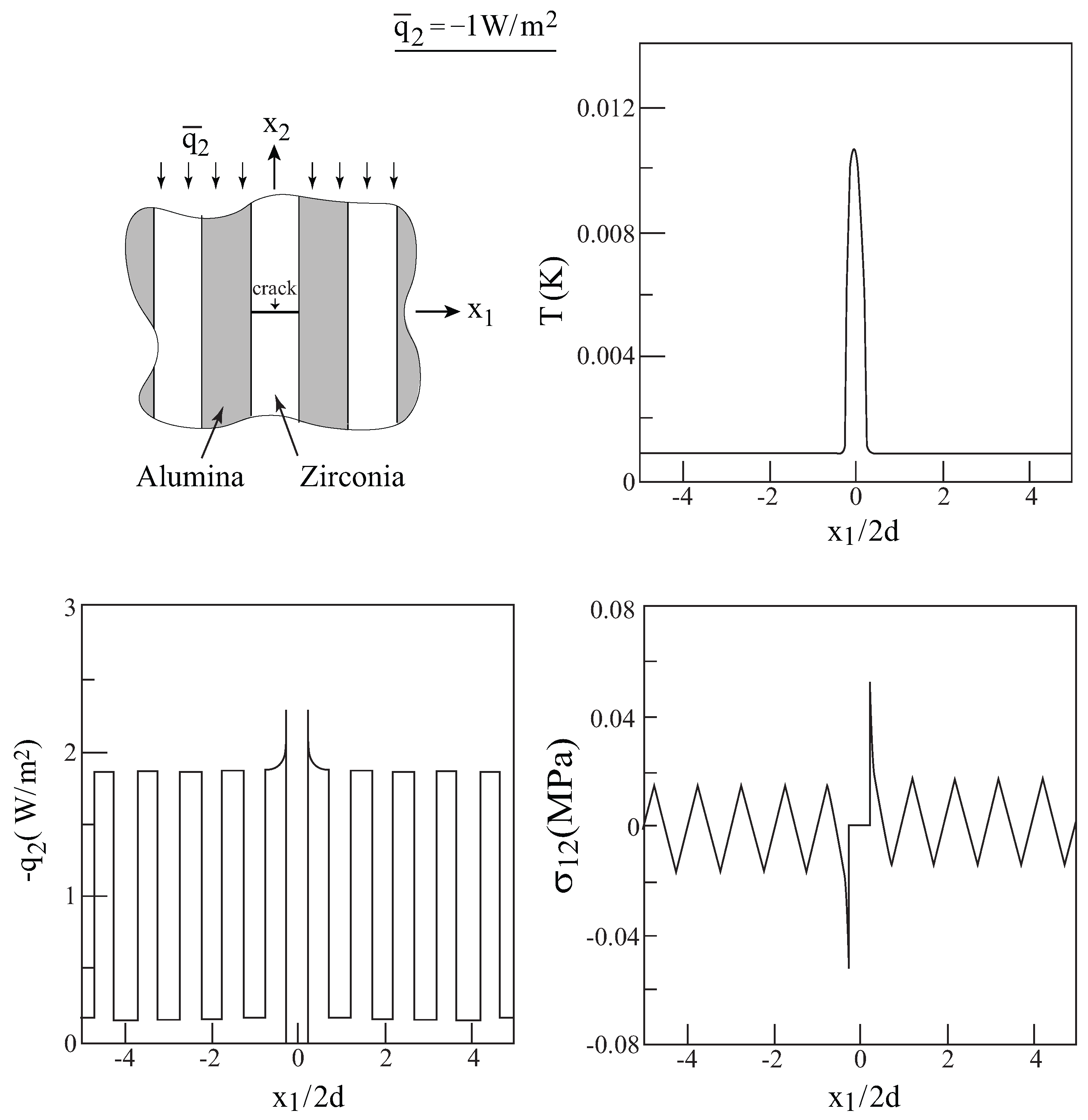
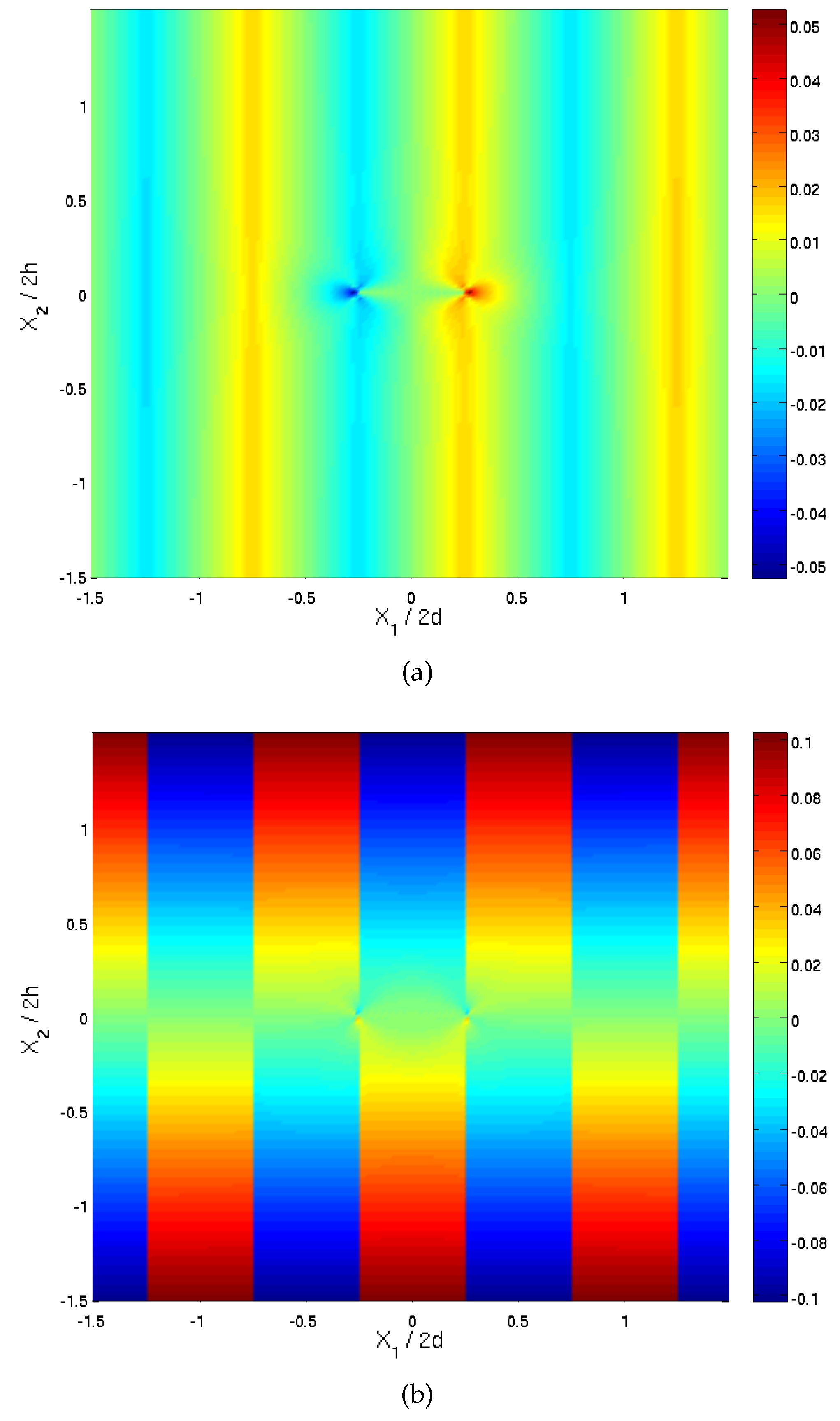
Next, let the axial direction of this homogenized transversely isotropic composite be oriented in the out-of-plane three-direction, and a crack of length 2a is introduced along the one-direction; see the inset in
Figure 3. In the present situation, the plane X
-X
is a plane of isotropy. In this case, the solution of [
7] is not applicable since out of the three roots
,
, two of them coincide, and in addition, these two coincide with
(i.e.,
). It is important however to verify this situation because in the analysis of the cracked (unhomogenized) fiber-reinforced composites and porous materials that will be considered in the next section, the axes of symmetry are oriented in the out-of-plane three-direction. For this case, it is however possible to verify our solution approach by utilizing the exact solution of [
4] for a crack embedded in isotropic material that is subjected to a remote heat flux.
The closed-form solution of [
4] for the temperature is given by:
where
and
is the heat conduction. The heat flux components can be readily determined from this relation:
The induced thermal stresses are determined from the two complex potentials
and
as follows.
The expressions of the complex potentials
and
are as follows:
where
G,
and
are the shear modulus, Poisson’s ratio and coefficient of thermal expansion of the isotropic material, respectively. The constants
,
G,
and
can be readily determined from the established effective conductivity, stiffness and thermal tensors of the considered composite.
Here, also, let the homogenized composite be subjected to a remote heat flux
=
W/m
in the two-direction. In
Figure 3, comparisons between this exact solution and the present one for the unidirectional carbon/epoxy composite whose axis of symmetry is oriented in the out-of-plane X
-direction with a transverse crack are shown. Very good agreements between the two solutions for the temperature, heat flux and the induced shear stresses along the crack line can be well observed.
6. Conclusions
A multiscale analysis is offered for the determination of the thermal and mechanical fields in cracked composites that are subjected to heat flow. This analysis has been verified by comparison with exact solutions for cracked isotopic and anisotropic thermoelastic materials (the solution of which is far more complicated than the former). Applications are given for three types of cracked composites, subjected to heat flow. The derived formulation however is general enough and allows the application of remote combined thermomechanical loading.
As discussed, the present method has certain advantages over a direct numerical approach. This stems from the fact that the applied boundary conditions (e.g., the applied heat flux) must be located at a sufficiently remote distance from the localized effects (e.g., a crack). As a result, the number of resulting equations when a direct numerical procedure is adopted might be extremely large. In the present method however, just one discretized cell in the transform domain needs to be considered. Increasing the remoteness of the applied boundary conditions does not affect the discretized cell analysis.
Applications of the present analysis have been presented for composites that consist of a single crack. It is however possible to apply it on composites with multiple cracks; see [
21], for example. The present formulation has been illustrated for a single crack, which forms a simple example of localized damage. It is however possible to consider other types of localized damage in composites, such as cavities, soft and stiff inclusions; see [
17]. In addition, the modeling of the interaction between two types of damage in composites that are subjected to heat flow (e.g., interaction between a crack and cavity) is possible. The results in the present article were confined to the application of remote heat flux; the method can be employed however to obtain the thermomechanical field distributions in damaged composites that are subjected to combined mechanical and heat flow.


