1. Introduction
Additive manufacturing using extrusion-based three-dimensional (3D) printing has revolutionized the production of complex parts. Material extrusion (FFF), one of the most common extrusion methods, is now being used worldwide to produce parts in a wide range of industries, from horticulture and automotive to space mission prototyping. FFF has also become useful in medicine, research, and education [
1]. Its widespread use can be attributed to its affordability, simplicity, and compatibility with a wide range of materials [
2]. FFF works by feeding a thermoplastic filament through a heated nozzle system, where it is melted and extruded through the nozzle’s orifice. The molten material is deposited as lines to form a shape that builds up layer by layer and solidifies as it cools to form the desired 3D object.
The quality and performance of printed FFF objects are highly sensitive to several FFF print process parameters. Nozzle orifice size is one of the most influential [
3]. Nozzle orifices are usually circular, with fixed diameters ranging from 0.2 to 1.2 mm. The most common size is 0.4 mm [
4]. The nozzle orifice size determines the width and height of the FFF line (commonly referred to as the extrudate or filament bead), which determines the print speed. It also influences the strength [
5], resolution, and quality of the printed part [
6]. For example, the difference in tensile strength between Polylactic Acid (PLA) plastic printed with 0.4 and 1 mm nozzle orifice diameters can be as much as 38% [
7]. Other research, [
8], showed that printing with a single extra-wide filament bead increased effective strength by up to 40% while simultaneously reducing printing time by 67%. Moreover, anisotropy, one of the main FFF problems, can be mitigated by extruding with a larger nozzle orifice size [
9]. A smaller nozzle orifice, on the other hand, offers the advantage of highly detailed [
10] and precise printing [
11].
Today, FFF printers come mostly with metal nozzles that have a well-defined and fixed circular orifice size. As a result, designers often have to choose a size that offers an optimal compromise between the strength and accuracy of the printed part. To print a model, it is first converted into instructions a 3D printer can understand using a software tool called a slicer, which produces a g-code file of commands that define the printer’s movements and actions.
Modern slicers can make minor adjustments to the size of the extruded filament bead by increasing or decreasing material flow; however, the effect of these adjustments is limited [
12] and assumes that the extruded material will be compressed between the nozzle tip and the surface of the previously deposited layer [
13]. If the filament bead is not being extruded onto a previous layer, such as when forming the bottom layer of a bridge, any size adjustment conducted by the slicer will fail.
Because they do not provide the necessary adaptability, traditional fixed-orifice nozzles are limiting. To move from balancing trade-offs to fully harnessing the power of optimization, a system is needed that is capable of continuously adjusting nozzle orifice size while printing.
Studies [
14,
15] introduced the possibility of using a variable-orifice-size nozzle. Combined with topological optimization, orifice size variability promises the extrusion of features with better mechanical properties while improving the cost efficiency of production and reducing the consumption of printing materials.
Variable-orifice-size nozzle technology promises improvements in many areas by enabling more adaptive, efficient, and sustainable additive manufacturing. Its ability to dynamically control material flow enables optimized resource utilization, customized structural properties, and increased design flexibility. Whether the approach is used for small objects or large-format printing, it supports rapid production, customization, and reduced waste. By meeting both functional and aesthetic requirements in a single process, variable-orifice-size nozzle technology opens new avenues for innovation across industries from manufacturing and design to architecture and beyond [
16].
The work reported here experimentally verifies the proposed nozzle system. It explores how well the design can change orifice size and how this affects the printing of PLA and PLA parts.
The goal is to contribute to the ongoing development of additive manufacturing and to establish a new and more flexible direction in FFF printing based on variable rather than fixed extruder nozzle orifice size, with recent studies, such as the one in [
17], also contributing valuable insights regarding the effects of fuzzy skin on printing properties and surface characteristics.
1.1. Variable Nozzle Orifice Size Concepts
In additive manufacturing, efforts are constantly being made to improve the quality and efficiency of 3D-printed parts. One proposed innovative solution is an extrusion nozzle that is able to continuously change the size of its orifice. This nozzle would dynamically adjust the thickness of the printed material bead based on the needs of the printed object, providing a number of benefits to both the manufacturing process and the final product. Variable-orifice-size nozzles for 3D printing have already been developed using different principles to dynamically control extrudate width. Each approach offers unique advantages and limitations in terms of mechanical complexity, adaptability, and empirical validation.
1.2. Existing Concepts of Variable-Orifice-Size Nozzle
One approach uses a segmented nozzle mechanism and works on a principle similar to crimping pliers [
18]. Multiple sliding steel triangular segments can be positioned to increase or decrease the size of the nozzle orifice. The cross-section of the resulting orifice is polygonal, with its number of sides determined by the number of sliding steel triangular segments. Although this method allows precise control of the nozzle orifice, it has drawbacks. One is the relatively high number of moving parts, increasing the risk of material leakage. In addition, because of the many segments, it is larger than a fixed orifice nozzle, and it requires more maintenance. Experimental verification of the concept has not yet been reported.
Another approach, known as Sculpman’s patented variable diameter nozzle technology [
19], features adjustable orifice width controlled by motors and a gear mechanism. With Sculpman’s nozzle, extrusion bead width can be continuously varied while printing, from zero to several millimeters. An advantage of this design is that it is mechanically simple. However, to take full advantage of bead width variability, the print head must remain perpendicular to the printing direction, and only the width is variable. This design has been patented and implemented in selected commercial systems.
A third approach uses a deformable elastic nozzle with a dynamic variable-size aperture [
20]. This system relies on the deformation of an elastic thin-walled hollow body. When external pressure is applied, the walls of the nozzle form a star-shaped cross-section that decreases in size with increasing pressure. At maximum compression, the walls form a small orifice. The elastic element of this design replaces the rigid moving parts, making the nozzle system relatively simple. However, the non-ideal ‘star’ shape of the outlet can lead to inconsistent extrusion, and there is a risk of leakage at points of contact where the walls bunch up. Experimental verification of the concept has not yet been reported.
A more advanced approach is demonstrated by the Adaptive Nozzle 3D Printing (AN3DP) system [
21], which enables active control of the size and shape of the nozzle orifice. To achieve this functionality, the AN3DP system uses eight independent actuators that continuously adjust nozzle geometry during the printing process. The nozzle interior is lined with a flexible silicone membrane that ensures smooth flow of the extruded material as the orifice shape adapts to the dynamic changes in the output profile. Although this design offers high versatility in extrusion control, it introduces significant hardware and control complexity. Real-time coordination of multiple actuators requires precise synchronization and advanced control algorithms.
The AN3DP system has not been tested with commonly used thermoplastics such as PLA but rather with shear-thinning inks. These inks flow under pressure but retain their shape after deposition. They do not require high processing temperatures, which simplifies the mechanical design and thermal management of the nozzle. Despite these limitations, the system has been successfully implemented and verified under controlled experimental conditions.
Each of these variable-orifice-size nozzle solutions comes with trade-offs between mechanical complexity, adaptability, and practical feasibility. Some favor simplicity and ease of integration, while some focus on precise control of filament shape and size. For some, experimental validation using traditional FFF materials has not been reported, and their compatibility with conventional thermoplastics such as PLA remains uncertain. Limited reported experimental validation and an apparent lack of testing under realistic conditions highlight the need for further research and experimental testing to assess realistic viability.
This article and the work reported here proposes and experimentally verifies a new variable-orifice-size nozzle concept and design. It explores the nozzle’s ability to vary its orifice size both without and with molten PLA being extruded through it. The study also demonstrates the ability of the variable-orifice-size nozzle system to print complete PLA parts. The goal of the work and this article is to contribute to the ongoing development of additive manufacturing and to establish a new and more flexible direction in FFF printing based on variable rather than fixed extruder nozzle orifice size.
1.3. Proposed Variable-Orifice-Size Nozzle Mechanism
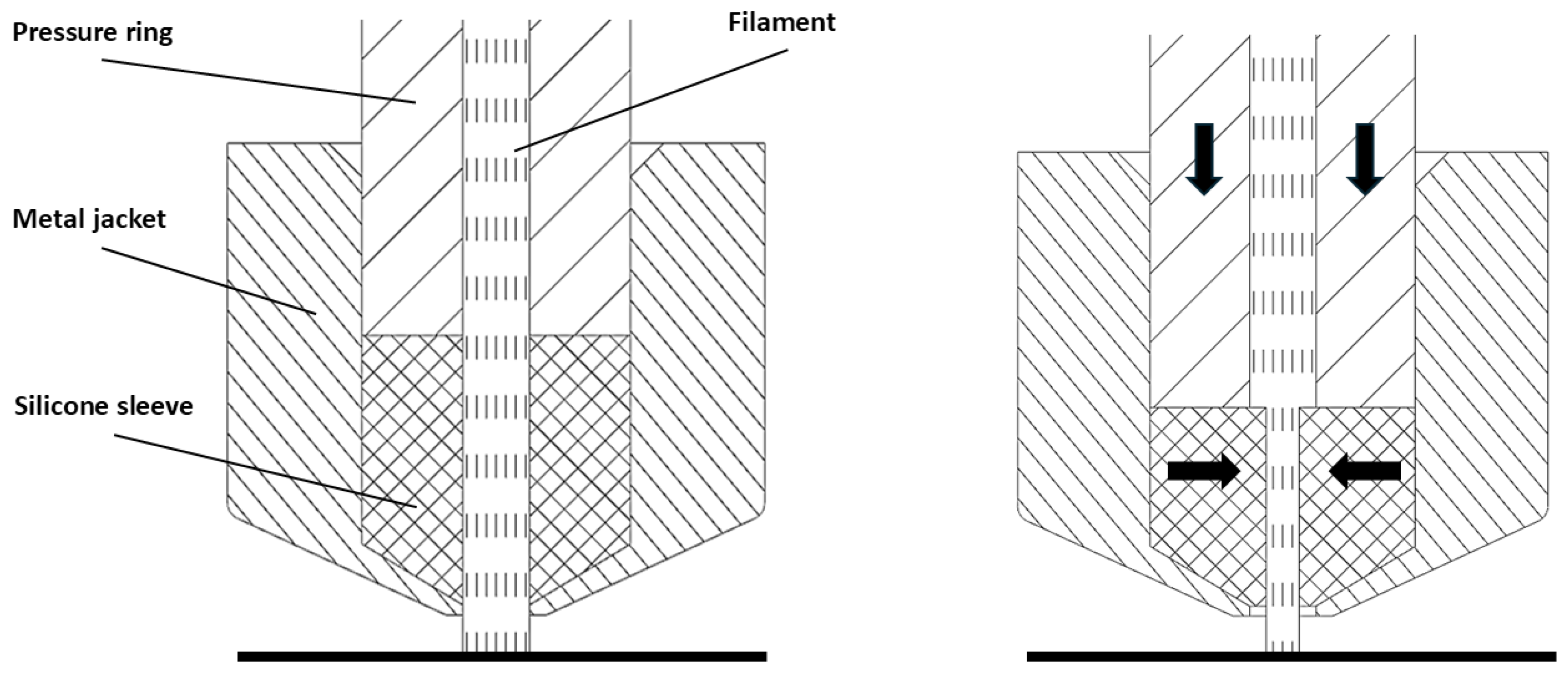
The proposed variable-orifice-size nozzle works on a simple but effective principle: pressure on a metal-jacketed elastomeric sleeve is controlled to change nozzle orifice size, which in turn changes the size of the extruded filament bead. The mechanism relies on three main components: the elastomeric sleeve (silicone in this case), the metal jacket, and a pressure ring to apply pressure to the sleeve. The nozzle orifice shrinks as pressure is applied. When pressure is released, the nozzle orifice returns to its original size due to the elasticity of the silicone insert. This principle is illustrated in
Figure 1.
During extrusion, molten filament flows through the pressure ring and elastomeric sleeve within the metal jacket. The elastomeric sleeve is compressed when the pressure ring is displaced into the metal jacket. This displacement can be achieved by moving either the pressure ring or the metal jacket. The resulting effect is the same. Under pressure, the elastomeric sleeve deforms according to the Poisson effect [
22]. Shortening the sleeve results in inward compensatory deformation that reduces the sleeve orifice diameter. When pressure is relieved, the sleeve lengthens and its orifice becomes larger. The displacement of the pressure ring into the elastomeric sleeve is directly related to the resulting nozzle orifice size, which directly affects the flow of the molten filament and the size of the filament extrudate or bead.
2. Materials and Methods
Several factors were considered when designing the variable-orifice-size nozzle. These included selecting the material for the elastomeric sleeve, designing the displacement mechanism, and ensuring that calibrations could be practically carried out.
2.1. Elastomeric Sleeve Material Selection
The most important part of the new nozzle system is the elastomeric sleeve. Several key performance criteria were established to select a suitable material. To accommodate the mechanical demands of the extrusion process, the ideal material had to be elastic and capable of 200% elongation without failure. It had to be thermally stable up to 225 °C to ensure reliable performance under the predicted operating conditions. High tensile strength and tear resistance were needed to reduce the risk of mechanical failure. Finally, the sleeve surfaces had to be abrasion-resistant to withstand the continuous molten filament flow of extrusion and contact with the interfacing nozzle components.
After evaluating various commercially available options, a candidate was selected. MM 940 [
23] silicone is manufactured by ACC Silicones (CHT Germany GmbH, 72072 Tübingen, Germany), which is now owned by the German CHT Group. The basic parameters of MM 940 silicone are listed in
Table 1.
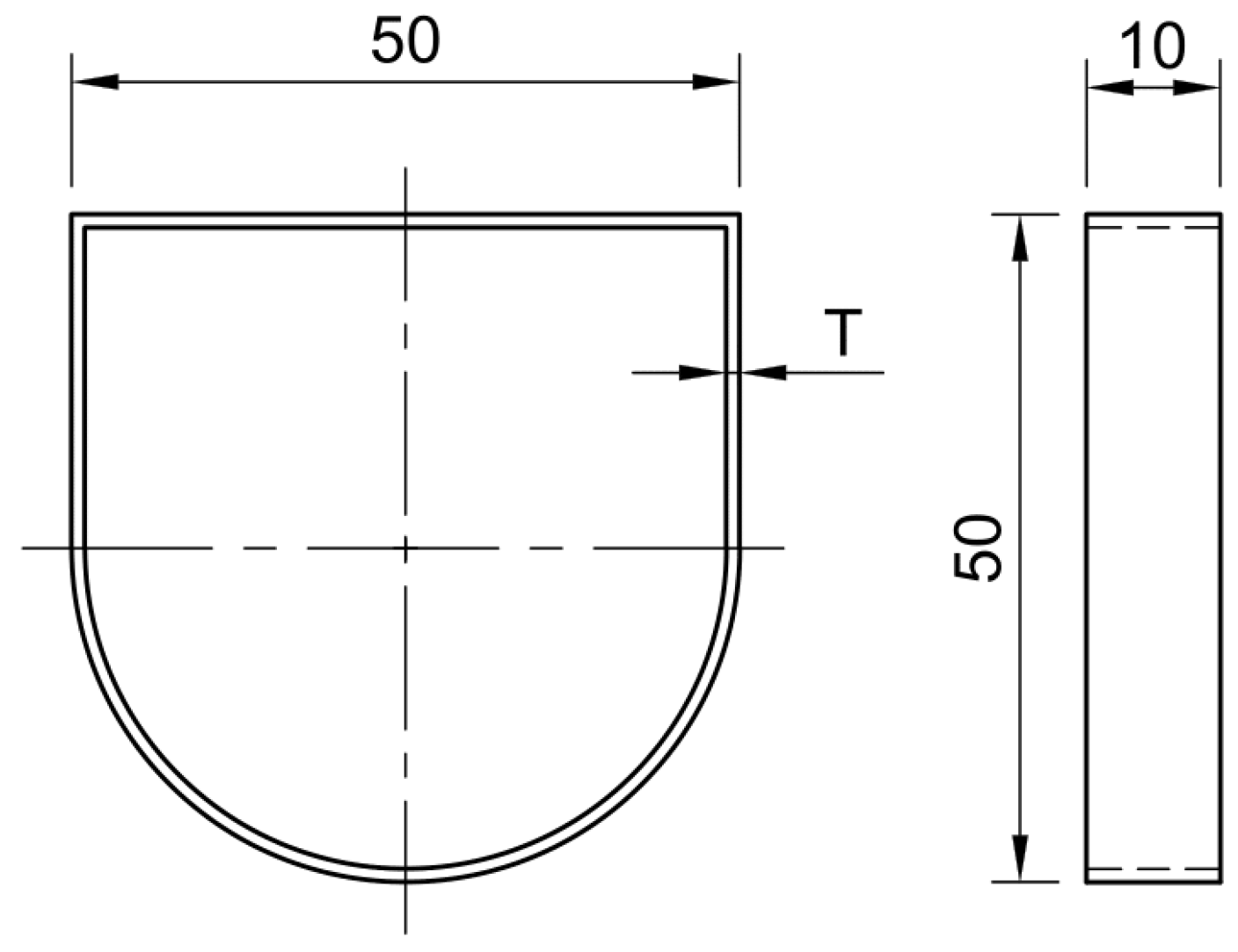
Figure 2 shows the cross-section and dimensions of the silicone sleeve. The silicone sleeve was designed to accommodate the 1.75 mm selected diameter for the 3D print filament. Knowledge gained from previous experiments, and manufacturing considerations, in particular, to simplify manufacturing of the metal jacket, were also important guidelines. The manufacturing method chosen for the silicone sleeve was casting. Additive manufacturing was used to build the casting mold.
2.2. Testing Mechanism
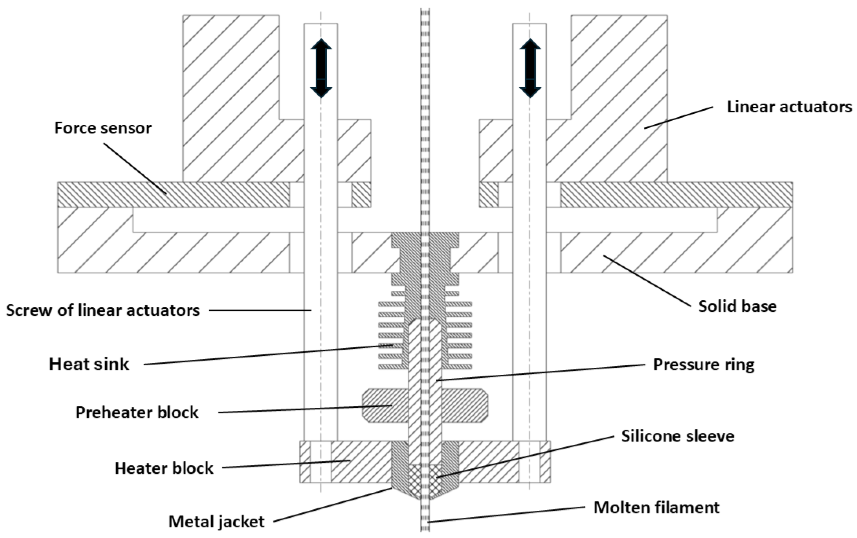
For a controlled relationship between the pressure ring and the metal jacket, a precise linear motion mechanism was designed to displace the compression ring relative to the jacket and compress and decompress the silicone sleeve. The mechanism and its relationship to the variable-orifice-size nozzle are illustrated in
Figure 3.
Linear motion for the variable-orifice-size nozzle is effected via a pair of linear screw actuators that provide controlled and accurate movement. Using two actuators instead of one ensures alignment of the nozzle jacket to the pressure ring, ensuring smooth and consistent compression of the silicone sleeve. The linear actuator screws are designed to move the metal jacket of the nozzle into or away from the pressure ring, which either compresses or relieves pressure on the silicone sleeve. Each is powered by a DC motor with encoder to control exact position and precise movement.
The linear actuators are mounted to a solid base through force sensors so forces applied can be measured. The presence of adequate force ensures that the pressure ring is making sufficient contact with the silicone sleeve to prevent leakage of molten filament.
The silicone sleeve sits inside the metal jacket, which screws into a heater block. Two 60 W heating elements keep the block and metal jacket at temperature, which is monitored via an NTC100K B3950 thermistor obtained from Majkl3D-Technology s.r.o. (Klatovy, Czech Republic). The pressure ring is also heated by a heater and thermistor that are part of a preheater block fixed to it. The primary function of the preheater is to soften the filament before it enters the silicone sleeve. However, it also helps to heat the silicone sleeve itself. A heat sink, which surrounds the upper end of the pressure ring, isolates the nozzle’s heated parts from the rest of the system. The heat sink is cooled by fans, which are not shown in
Figure 3.
2.3. Calibration of Variable-Orifice-Size Nozzle Printhead
The variable-orifice-size nozzle printhead must be calibrated before each print. This is completed by observing the nozzle orifice from underneath as the silicone sleeve is alternately compressed and relieved of pressure. A Dino-Lite digital microscope camera (model AM4815ZTL) [
24] obtained from DREXX s.r.o. (Líský, Czech Republic), was used to observe the nozzle orifice for this study.
The calibration process begins by moving the printhead into position above the camera. Next, the silicone insert is installed into the metal jacket. The pressure ring is then guided downwards onto the silicone sleeve until force is detected by the force sensors. The pressure ring is then retracted 3 mm to provide sufficient clearance to accommodate any subsequent thermal expansion of the silicone. The heater and preheater block heating elements are then turned on to bring the nozzle assembly to 225 °C.
Once printhead temperature has stabilized at 225 °C, the linear actuators slowly drive the pressure ring down onto the silicone sleeve as the microscopic camera continuously monitors the sleeve orifice. Once the camera detects silicone sleeve compression and the force sensors read 20 N (experimentally determined value at which the printing material no longer flows between the pressure ring and the silicone sleeve; this value was experimentally determined for PLA material with a safety factor of 1.5 against leakage, at the maximum volumetric flow rate of 5.6 mm3/s and maximum temperature of 225 °C, when the silicone is at its softest), pressure ring movement is stopped. This establishes the minimum sleeve compression or maximum orifice size position. The position of the pressure ring is recorded, and the size of the orifice is measured. The pressure ring is then driven further into the silicone sleeve. When the sleeve orifice reaches its perceived minimum size, pressure ring movement is once again stopped. This is the maximum silicone sleeve compression position. It is recorded, and the minimum orifice size is measured.
2.4. Feed Rate Speed Calculation for Filament into the Nozzle
Filament feed rate or flow calibration comes after nozzle orifice size calibration. Precise control of filament flow is necessary to achieve good print quality and accuracy. Flow calibration is carried out by printing beads of filament, measuring their width and height, and comparing the measurements to those set in the slicer. Feed rate is then adjusted until the measured and set filament extrudate dimensions agree.
Being able to change nozzle orifice size on the fly complicates filament feed rate control. Constant printhead speed was assumed for these experiments, so it was only necessary to determine the dependence between nozzle orifice size and the flow of the filament bead and between filament size and feed rate.
The calibration was carried out for both the smallest and largest nozzle diameters. The subsequent results were recalculated using the images shown in
Section 4.1 to match the desired compression. In the experiments, one variable was constrained: the printhead speed was set to a constant 20 mm/s. For variable speeds, the volumetric flow rate was recalculated proportionally to the given speed.
4. Results
A series of experiments were carried out to evaluate the behavior of the variable-orifice-size nozzle. Its orifice was examined with and without filament present. The first part of the analysis focused on the relationship between the compression of the silicone sleeve and the resulting change in its orifice, i.e., its internal cross-sectional area. This examination revealed a clear correlation between the applied pressure (deformation) and the size of the nozzle orifice.
Further investigation explored hysteresis revealed during compression and subsequent release of pressure for the silicone sleeve. This hysteresis was observed when the silicone sleeve was compressed without the filament present and during filament extrusion. The silicone material exhibited a viscoelastic response that may influence the control accuracy of the variable-orifice-size nozzle.
A method was developed to indirectly measure the cross-sectional area of the nozzle orifice during filament extrusion. Direct observation using the microscopic camera was not possible. The results of the indirect measurement confirmed that hysteresis was also present during filament extrusion. A non-linear response under pressure was evident.
Finally, the functionality of the variable-orifice-size nozzle was validated in practice by printing three sample parts. These prints demonstrated that the system could reliably adjust the outlet diameter and produce consistent wall thicknesses corresponding to different nozzle settings.
4.1. Optical Measurements of the Nozzle Orifice Cross-Sectional Area
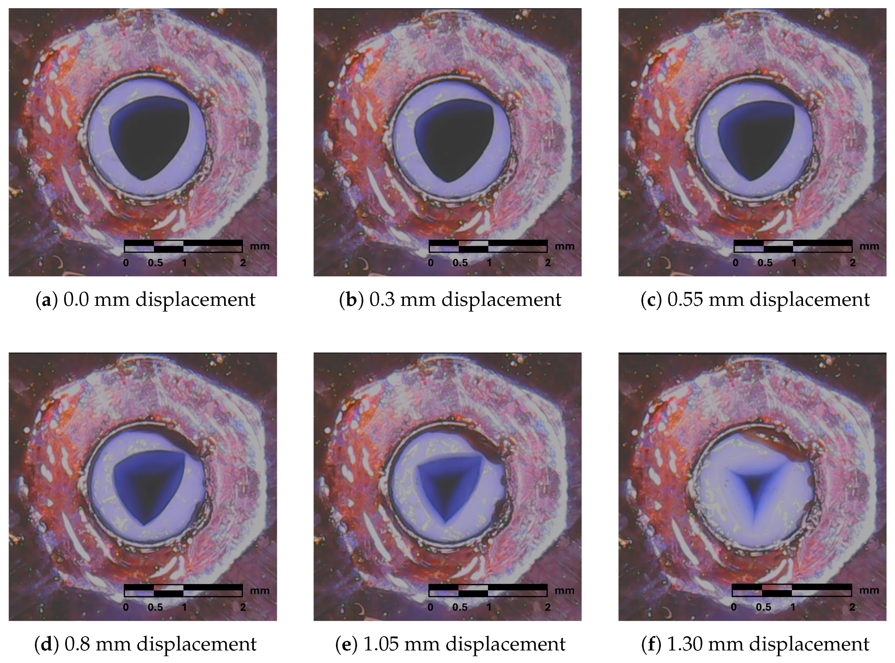
Figure 7 shows the gradual change in the shape and dimension of the nozzle outlet hole cross-section when the silicone insert is compressed. The compression is applied perpendicular to the view of the image. At ithe nitial compression, the shape of the outlet opening is between a circle and a triangle with rounded corners. As the silicone liner is gradually compressed, not only does the cross-section of the outlet hole become smaller but the shape of the outlet hole becomes more and more like a triangle. Up to
Figure 7f, the shape of the exit hole resembles the shape of a three-pointed star.
Multiple causes may result in this behavior of the silicone sleeve. Precision manufacturing of both the silicone sleeve and the metal jacket can play an important role. Also, uneven friction between the silicone sleeve and the metal jacket can significantly affect the resulting shape of the nozzle orifice. Temperature combined with the effect of pressure could be another cause.
Figure 8 shows the relationship between the compression of the silicone sleeve and the nozzle orifice cross-sectional area. Four series of measurements were taken during which the silicone sleeve was gradually compressed and then the pressure was released. The change in orifice size becomes more apparent after the pressure ring compression displacement exceeds 0.7 mm. Between 0.7 mm and 1.3 mm, there is significant change in orifice size, i.e., from 1.4 mm
2 to 0.25 mm
2.
In the case of pressure release, compression displacements ranging from 0.3 mm to 1.3 mm are significant. A comparison of the compression and release curves reveals hysteresis. This effect can be attributed to the combination of elastic and viscoelastic properties of the silicone material and must be accounted for within the control algorithms of the variable-orifice-size nozzle.
A comparison of the compression and release curves also reveals good repeatability of the measurement results. This indicates that the system does not exhibit cumulative deformation or material fatigue under the conditions tested and remains consistent in its output behavior.
Figure 9 shows the relationship between the compression displacement of the silicone sleeve and the minimum cross-section of its orifice. The change in cross-sectional area becomes more pronounced once the pressure ring displacement value exceeds 0.5 mm. From 0.5 mm to 1.3 mm compression displacement, more gradual orifice size change is observed, from 1.17 mm
2 to 0.05 mm
2. A comparison of the compression and release curves shows even more hysteresis. A comparison of
Figure 8 and
Figure 9 shows that there is noticeably more constriction at the top of the silicone sleeve than at the bottom. The extra constriction at the top of the silicone sleeve, which restricts the flow of the molten filament material, limits how small the actual orifice can practically be set.
Also in this case, the comparison of the compression and release curves shows very good repeatability of the measurement results and consistency of the behavior of the tested system.
4.2. Measuring the Cross-Section of Filament Extrudate
Measurement of the filament extrudate cross-section was also conducted optically. The silicone sleeve was gradually compressed in 0.05 mm increments until its maximum compression level was reached. The pressure on the silicone sleeve was then released in similar equal steps. In contrast to the measurements taken without filament extrusion, the silicone sleeve during extrusion could only be compressed by 0.5 mm. At higher compression, the silicone sleeve itself was already damaged due to the pressure of the flowing printing material.
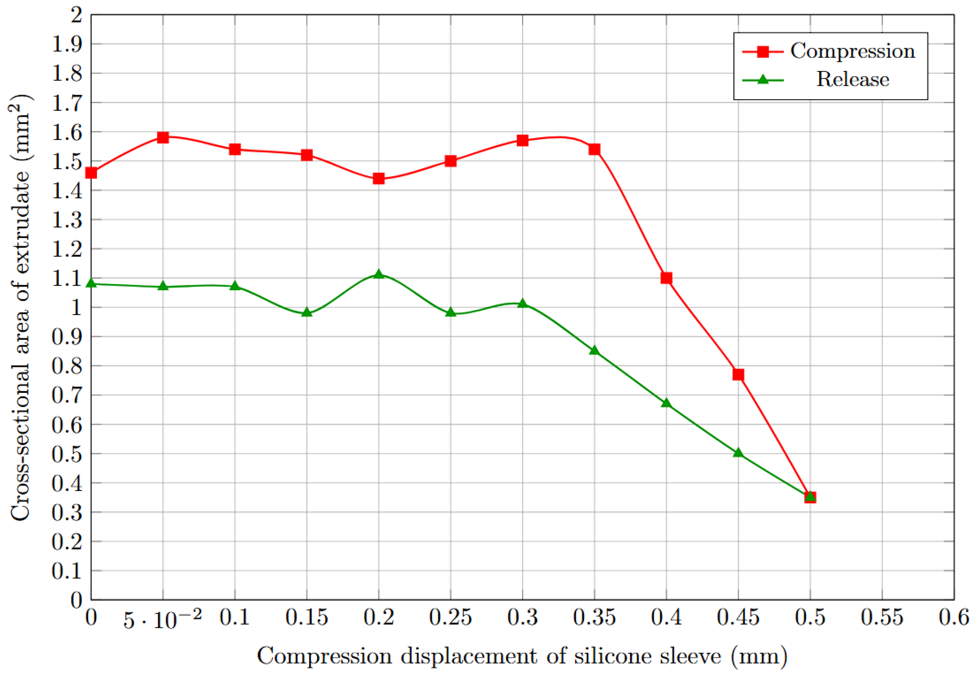
The compression curve in
Figure 10 shows no overall reduction in the cross-sectional area of the filament extrudate during the first 0.35 mm of silicone sleeve compression displacement, just a fluctuation between 1.4 mm
2 and 1.6 mm
2. From 0.35 mm to 0.5 mm, the cross-sectional area dropped significantly. As pressure was relieved, the cross-sectional area of the orifice increased again, but more gradually. As with the compression curve, the extrudate diameter fluctuated around a constant value (1 to 1.1 mm
2) as the compression displacement was further relieved from 0.3 mm to 0.0 mm. The extrudate cross-sectional area during compression was 25% higher than the area during compression displacement release from 0.0 mm to 0.3 mm. This behavior is significantly different than the orifice behavior that was observed without filament being extruded. See
Figure 9.
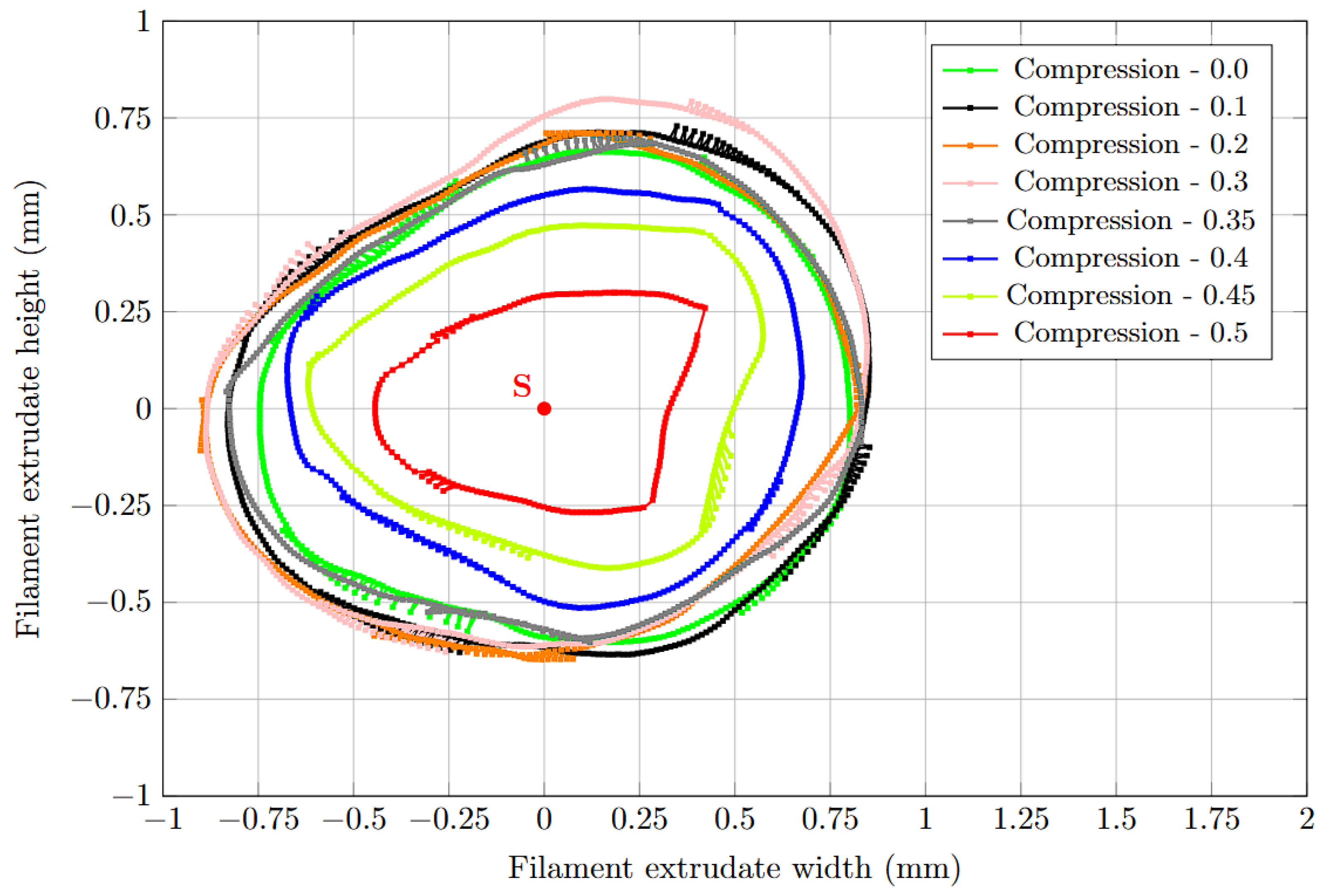
Figure 11 shows the cross-sectional shapes of the filament extrudate samples. For clarity, the samples are shown partly in 0.1 mm increments and partly in 0.05 mm increments. The cross-section shapes are similar over the compression range from 0.0 mm to 0.35 mm and are close to the desired circular shape. It is only when the compression is in the range of 0.35 mm to 0.5 mm that the cross-sectional shape of the sample is significantly reduced.
Gradually, the cross-sectional shape also changes, resembling the shape of a mirror-inverted letter ’D’ at maximum compression. This change in cross-sectional shape is probably due to inaccuracies in the manufacture of both the individual nozzle parts and the silicone sleeve itself. The uneven level of friction between the metal jacket and the silicone sleeve may also have played a significant role.
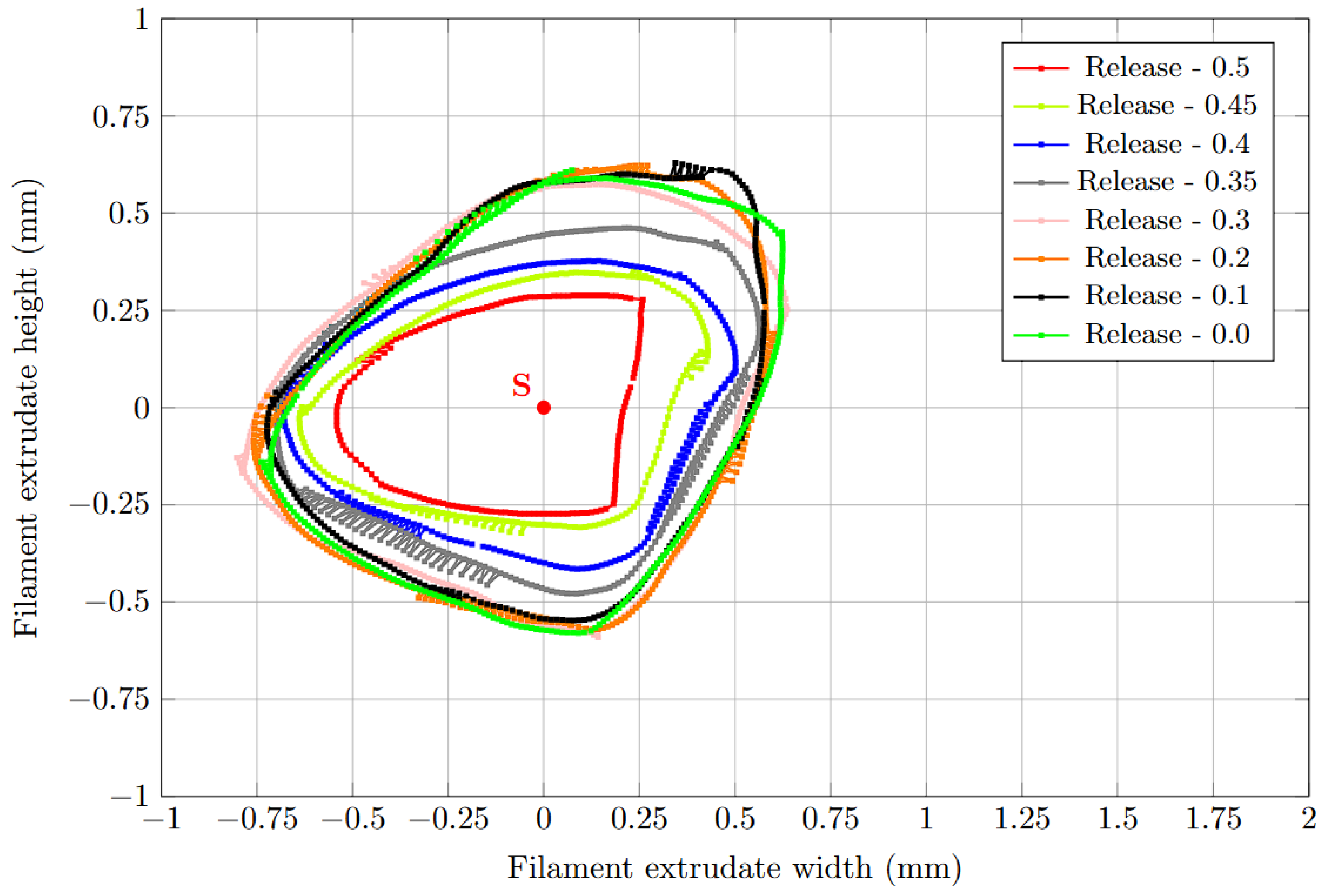
Figure 12 shows the cross-sections of the filament bead samples extruded during compression release. Not only do the cross-sectional areas along the bead gradually increase in size but their shapes also change. Rather than being circular, the cross-sections resembled a combination of an ellipse and a triangle with rounded corners. The difference between the heights and widths was approximately 25% when compression was relieved from 0.3 mm, which can have a negative effect on print quality and accuracy.
Comparing the previous
Figure 9 and
Figure 12 reveals a similarity between the shape of the silicone sleeve orifice and the cross-sectional shape of the filament extrudate. However, there is a substantial size difference that is due to the pressure exerted by the material as filament is extruded through the silicone sleeve.
4.3. Wall Thickness Measurement of the Printed Sample Parts
Three sample parts were printed. The nozzle orifice cross-sectional area was set to 1.50 mm
2 for the first, which corresponds to the equivalent of a 1.4 mm nozzle orifice diameter (close to maximum size). For the second part, the nozzle orifice cross-sectional area was set to 0.35 mm
2, which corresponds to an equivalent 0.7 mm nozzle orifice diameter (close to minimum size). For the third sample part, the nozzle orifice cross-sectional area was set to 1.50 mm
2 (1.4 mm diameter) for the first half of the print and 0.35 mm
2 (0.7 mm diameter) for the second half of the print.
Figure 13 shows the wall thickness measurement for each sample part taken afterwards using the Keyence LJ-X8080 laser profilometer.
The wall thickness measured for the first sample part was 1.4 mm (
Figure 13), which was 0.02 mm, or approximately 1.5%, larger than the equivalent nozzle orifice diameter used to print it. For the second sample part (
Figure 13b), the measured wall thickness was 0.7 mm, again 0.02 mm larger than the equivalent nozzle orifice diameter, representing approximately a 3% increase. For the third sample part, the lower and upper wall thicknesses (measured during the first and second halves of the print) were recorded as well.
The wall thickness measured for the first sample part was 1.4 mm (
Figure 13). It was 0.02 mm or approximately 1.5% larger than the equivalent nozzle orifice diameter used to print it. For the second sample part (
Figure 13b), the measured wall thickness was 0.7 mm, which was again 0.02 mm larger than the equivalent nozzle orifice diameter (approximately 3% larger). The lower and upper wall thicknesses (first half and second half of the print) measured for the third sample part (
Figure 13c) were 1.4 mm and 0.7 mm, respectively. These were 0.05 mm or approximately 3.6% and 0.01 mm or approximately 1.5% larger than the target equivalent nozzle diameters, respectively.
All the wall thicknesses measured for the three sample parts were within 4% of the equivalent nozzle orifice diameters used to print them. For the third sample part, the transition from thicker to thinner wall was not abrupt. It took between 15 and 20 s over the course of two printed layers.
5. Discussion
A variable-orifice-size nozzle has been proposed and was evaluated. Its design is based on deformation of a flexible and temperature-resistant silicone sleeve jacketed by a metal nozzle. Three experiments were carried out to verify the functionality of the proposed solution.
In the first experiment, the response to compression and release of pressure without molten filament flow through the jacketed silicone sleeve was observed using a microscopic camera. The nozzle orifice changed in cross-sectional area from 0.25 mm
2 to 1.50 mm
2, which would correspond to the equivalent of circular cross-sections with diameters ranging from 0.6 mm to 1.4 mm. Previously,
Figure 9 showed the dependence of the change in nozzle orifice cross-sectional area on the magnitude of silicone sleeve compression displacement. The curves describing the behavior of the silicone sleeve during compression and release of pressure revealed hysteresis.
Given the progression of the curves, it would be possible to mathematically describe the dependence between hole cross-section and silicon sleeve compression. This description could then be used to control the nozzle orifice size during printing. From this perspective, the performance of the prototype variable-orifice-size nozzle system seems to justify further testing.
The second experiment was designed to investigate the behavior of the silicone sleeve under compression while molten filament was pushed through its orifice. Direct observation was not possible, so measurements were taken from sample filament extrudate to compare with the nozzle orifice settings. It soon became clear that a smaller range of sleeve compression would be needed. Compression displacement values exceeding 0.5 mm during filament extrusion damaged the silicone sleeve. Nonetheless, the nozzle still managed changes in orifice cross-sectional area from 0.35 mm2 to 1.60 mm2, which would correspond to equivalent orifice diameters ranging from 0.7 mm to 1.4 mm.
The difference between the achieved minimum and maximum equivalent diameters was greater than 100% or more than double.
Figure 10 showed the hysteresis between the curves for compression and release of pressure of the silicone sleeve. However, compared to the first experiment, the silicone sleeve failed to return to its initial state after release of pressure. The difference between the cross-section size at the beginning of the compression cycle and at the end is 25%. The reason for this behavior is explained in the evaluation of the third experiment.
Three samples were printed during this process. For two of them, the nozzle orifice cross-sectional area was set constant throughout the printing process. The wall thickness of these samples matched the overall print process setup and expected results within less than 4% deviation. For the third sample, the nozzle orifice size was changed mid-print.
Figure 13c reveals that the change in wall thickness did not occur immediately but over the course of two layers. This corresponds to a 15 to 20 s time interval. This also implies that nozzle orifice size change is not stepwise. Instead, there is a delay that will vary depending on the magnitude of the diameter change.
Figure 13c was generated during the scanning of the object using the Keyence LJ-X8080 laser profilometer.
The variable-orifice-size nozzle functioned as planned, but with the limitation of the rate of change of its diameter. This delay also partly explains the difference between the cross-sectional size at the beginning and end of the compression cycle shown previously in
Figure 10. In this experiment, the time required for the silicone sleeve to adjust to the new diameter setting was planned for. The second reason is the continuous pressure exerted by the molten filament flowing through the silicone sleeve. Therefore, it can be assumed that, if a longer period of time was allowed for the silicone sleeve to adjust to the new setting, the difference between the cross-sections would be less than the 25% observed. To counteract the effect of the flow of the molten filament through the silicone sleeve, structural modifications to the nozzle that would enable changing orifice diameter without relying on the elastic properties of the silicone material would be necessary.
The principle of this variable-orifice-size nozzle was prototyped and proven to work via testing. This testing revealed an issue with hysteresis between compression and decompression corresponding to decreases and increases in orifice size. It seems that this issue could be managed with more care in the manufacturing of the nozzle system and the introduction of high-precision and high-quality nozzle elements. The long-term durability of the silicone sleeve could also be an issue.
If these shortcomings are eliminated, the variable-orifice-size nozzle could be an interesting solution in terms of possible industrial application. There is room for further investigation both in terms of the proposed solution’s functionality and optimization and the materials from which the individual parts of the nozzle could be manufactured.
