Abstract
Chromium–aluminum nitride (CrAlN) coatings were deposited on polished H13 tool steel substrates using direct current (DC) magnetron sputtering. The Cr/Al composition in the target was varied by inserting either four or eight chromium (Cr) plugs into cavities machined into an aluminum (Al) plate target. Nitrogen was introduced as a reactive gas to facilitate the formation of the nitride phase. Coatings were deposited at substrate bias voltages of −30 V, −50 V, and −60 V to study the combined effects of composition and ion energy on coating properties. Compositional analysis of coatings deposited at a −50 V bias revealed Cr/Al ratios of approximately 0.8 and 1.7 for the 4- and 8-plug configurations, respectively. This increase in the Cr/Al ratio led to a 2.6-fold improvement in coating hardness. Coatings produced using the eight-Cr-plug target exhibited a nearly linear increase in hardness with increasing substrate bias voltage. Cross-sectional scanning electron microscopy revealed a uniform bilayer structure consisting of an approximately 0.5 µm metal interlayer beneath a 2–3 µm CrAlN coating. Surface morphology analysis indicated the presence of coarse microdroplets in coatings with the lower Cr/Al ratio. These microdroplets were significantly suppressed in coatings with higher Cr/Al content, especially at increased bias voltages. This suppression is likely due to enhanced ion bombardment associated with the increased Cr content, attributed to Cr’s relatively higher atomic mass compared to Al. Coatings with lower hardness exhibited greater scratch resistance, likely due to the influence of residual compressive stresses. The findings highlight the critical role of both Cr/Al content and substrate bias in tailoring the tribo-mechanical performance of PVD CrAlN coatings for wear-resistant applications.
1. Introduction
Physical vapor deposition (PVD) magnetron sputtering is widely used to produce ceramic-based hard and protective coatings with typical thicknesses in the range of 3–5 µm for wear-resistant applications [1]. These thin films enhance surface hardness while preserving the toughness of the substrate. In a direct current (DC) magnetron sputtering system, a plasma is generated by ionizing an inert gas (typically argon) under a strong electric field applied between the negatively biased target and the grounded chamber. Positively charged argon ions bombard the target, ejecting atoms that are subsequently deposited on the substrate to form a dense adherent layer [2]. The process allows for compositional control, enabling the deposition of multi-component, alloyed, and compound films through the use of reactive gases like nitrogen or oxygen. As such, PVD is a versatile technique for coatings in electronics, biomedical devices, corrosion protection, and tribological applications [3,4].
Nitride coatings based on titanium (Ti) and chromium (Cr) are extensively employed to improve the wear resistance, oxidation resistance, and performance of cutting tools [5,6]. To address the demands of high-speed machining and dry cutting, aluminum has been introduced into TiN and CrN coatings, giving rise to TiAlN and CrAlN systems. These ternary coatings offer superior thermal stability and high-temperature oxidation resistance compared to their binary counterparts [7,8]. In Cr1-xAlxN coatings, aluminum stabilizes the cubic CrN phase (NaCl-type) up to a critical solubility limit (x ≈ 0.6–0.7), beyond which phase transformation to hexagonal AlN (wurtzite structure) can occur, adversely affecting the coating’s tribological performance [9,10].
The mechanical and tribological behavior of CrAlN coatings is strongly influenced by both intrinsic factors (e.g., microstructure, composition, defect density) and extrinsic deposition parameters such as target composition, N2/Ar gas ratio, substrate temperature, and substrate bias voltage. Among these parameters, substrate bias voltage plays a pivotal role in modulating the energy of ions impinging on the substrate surface, thereby impacting coating density, grain refinement, residual stress, and adhesion. While increased bias voltage enhances densification and hardness, excessive values may induce high compressive stresses leading to microcracking [11]. The coating composition can be fine-tuned using Cr–Al targets (e.g., Cr50Al50) or hybrid target configurations to vary Al content in the film.
Numerous studies have explored the interplay between deposition parameters and the performance of CrAlN coatings. Bobzin et al. [12] studied the wear behavior of Cr1-xAlxN coatings with varying aluminum content and reported that Cr0.77Al0.23N exhibited optimal adhesion, microhardness (1465 HV), fine grain size (6.3 nm), and the lowest wear rate compared to CrN and AlN. Wang et al. [11] demonstrated that controlled substrate bias voltage can concurrently enhance hardness and toughness due to increased compressive stress and microstructural refinement. Similarly, Lv et al. [13] employed mid-frequency magnetron sputtering with Cr and Cr50Al50 targets and found that increasing bias voltage refined the microstructure and improved hardness and wear resistance at intermediate voltages, while excessive bias led to Al re-sputtering and stress-induced degradation. Tang et al. [14] used high-power impulse magnetron sputtering (HiPIMS) with a Cr50Al50 target to systematically examine the effects of nitrogen content and substrate bias. They found that a 100% N2/Ar flow ratio yielded optimal crystallinity and mechanical properties, whereas a −120 V bias voltage achieved peak hardness (35.4 GPa) and wear resistance due to grain refinement and stress-induced densification.
The present study investigates the influence of Cr/Al content and substrate bias voltage on the mechanical and scratch resistance of CrAlN coatings deposited via DC magnetron sputtering on H13 tool steel. Film composition was varied by altering the number of machined Cr plugs inserted in an Al target plate, enabling tailored Cr/Al ratios. The scratch resistance and failure behavior of the coatings were characterized using scratch testing, supported by microhardness measurements and microstructural analysis to correlate deposition conditions with coating performance.
2. Experimental Procedure
2.1. Coating Samples
CrAlN coatings were deposited on H13 tool steel substrates with a diameter of 5 cm. Prior to deposition, the samples were ground, mirror-polished, ultrasonically cleaned in acetone, and dried. The sputtering process was carried out in a vacuum chamber maintained at a base pressure of 2.0 × 10⁻³ Pa, using a rotating sample holder to ensure uniform film deposition. A schematic of the aluminum target with embedded chromium inserts is shown in Figure 1. Two target configurations, containing 4 and 8 Cr plugs, respectively, were used to vary the Cr/Al ratio in the coatings. Substrate bias voltages of −30 V, −50 V, and −60 V were applied for the 8-Cr plug configuration, while a −50 V bias was used for the 4-Cr plug configuration. All other deposition parameters were held constant. Argon was supplied at a flow rate of 15 standard cubic centimeters per minute (sccm) as the working gas, while nitrogen was introduced as the reactive gas to form CrAlN compound coatings. The reactive gases were introduced into the vacuum chamber to react with the sputtered target atoms. The target temperature during deposition was maintained at approximately 200 °C. All coatings were deposited under a fixed deposition duration of 1 h.
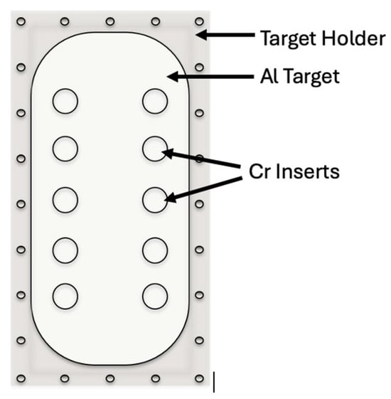
Figure 1.
Schematic illustration of the aluminum plate target with machined cavities for chromium (Cr) plug insertion, used in the deposition of CrAlN coatings via DC magnetron sputtering.
2.2. Hardness
The hardness of the coatings was measured using a micro-indentation technique, which employs a diamond indenter of defined geometry. In this method, the indenter is pressed into the sample surface under a specified load, and hardness is determined by dividing the applied load by the projected contact area. Micro-indentation is a widely accepted technique for evaluating the hardness of thin-film coatings [15]. A square pyramidal Vickers indenter—with opposite face angles of 136°, edge angles of 148°, and face angles of 68°—was used for the measurements. To minimize substrate influence, the indentation depth was limited to less than 10% of the coating thickness. Given that the coating thickness ranged from 2 to 3 µm, the indentation depth was maintained below 250 nm to minimize the influence of the substrate. Accordingly, an applied load of 80 mN was selected to ensure the indentation depth remained within this limit.
2.3. Scratch Test
The mechanical properties of thin films and coatings, such as adhesion, fracture resistance, and deformation behavior, were evaluated using scratch testing. In this technique, a controlled scratch is generated on the coating surface using a sharp indenter tip, typically made of diamond or a hard metal (e.g., WC). The indenter is drawn across the coated surface under a progressively increasing load until coating failure occurs. The onset of coating failure is identified by critical loads, which are influenced by a variety of factors, including the adhesion strength between the coating and substrate, coating thickness, mechanical properties, residual stress, tip radius, loading rate, interface flaw distribution, and friction between the indenter and coating surface [16].
In the present study, all scratch testing parameters were kept constant across all samples to ensure comparability. Each sample was subjected to multiple tests to improve reliability. Coating failure under increasing shear stress and frictional force may result in phenomena such as spallation (fragment detachment) and buckling (delamination), both of which are driven by interfacial stresses. It is well recognized that coating failure is a complex process, often involving multiple failure modes simultaneously [17].
Adhesion performance was assessed using three critical loads: Lc1, Lc2, and Lc3, each corresponding to a distinct failure mechanism. Lc1 denotes the onset of cohesive failure within the coating itself (e.g., crack formation without detachment). LC2 marks the initiation of adhesive failure, typically associated with coating detachment such as spallation or delamination. Lc3 represents extensive interfacial spallation, indicating progressive failure beyond Lc2. These critical loads were further used to estimate the crack propagation resistance (CPR), a qualitative metric calculated as CPR = Lc1 * (Lc2—LC1), where Lc1 and Lc2 refer to the lower and upper critical loads, respectively [18]. While CPR offers comparative insight into a coating’s resistance to crack growth under stress, it is acknowledged that critical loads alone do not directly quantify adhesion strength due to their sensitivity to testing and material parameters [19]. Scratch testing was performed using a Microcombi tester (CSM Instruments), equipped with a Rockwell-type diamond indenter (I-170) featuring a tip radius of 100 μm. The indenter was linearly traversed over a 10 mm path on the coated surface, while the normal load was increased from 0.03 N to 10 N at a loading rate of 1.0 N/mm and a speed of 5 mm/min. During the test, parameters such as friction force, coefficient of friction, and acoustic emission signals were continuously monitored. Critical loads were identified by correlating sudden changes in these signals with visible coating failure in the scratch tracks [20,21]. Prior to testing, all specimens were ultrasonically cleaned to remove surface contaminants. Post-test analysis of coating failure morphology was conducted using field-emission scanning electron microscopy (FESEM) and energy-dispersive X-ray spectroscopy (EDX) on a Tescan Lyra 3 instrument, Brno, Czech Republic.
3. Results and Discussion
3.1. Chemical Composition
The average chemical compositions of the coatings were determined using energy-dispersive X-ray spectroscopy (EDX), based on more than three independent measurements, and are summarized in Table 1. For coatings deposited using targets with eight Cr plugs, the Cr/Al ratios were found to be 2.1, 1.7, and 2.0 at substrate bias voltages of −30 V, −50 V, and −60 V, respectively. When comparing targets containing four or eight Cr plugs deposited at a fixed bias voltage of −50 V, the Cr/Al ratios were approximately 0.8 and 1.7, respectively. As expected, increasing the number of Cr plugs in the target led to a higher Cr/Al ratio in the resulting coating. However, the variation in the Cr/Al ratio with bias voltage is not straightforward to interpret. A plausible explanation may involve the significant difference in atomic mass between Cr and Al. Since Cr has nearly twice the atomic mass of Al, it may be more susceptible to re-sputtering or reflection from the growing film surface. As a result, the Cr/Al ratio in the coating could be governed by a competing interplay between increased ion penetration at higher energies and the preferential re-sputtering of the heavier Cr atoms under energetic ion bombardment.

Table 1.
Average chemical composition of coatings deposited at bias voltages of −30, −50, and −60 V, using an Al target with either eight or four Cr plugs inserted.
3.2. Surface Morphology
The surface morphologies of the coatings deposited under various conditions were examined using field emission scanning electron microscopy (FE-SEM), as shown in Figure 2. Coatings deposited using the target with eight Cr plugs exhibited smooth surfaces across all applied bias voltages (Figure 2a,b,d). An increase in bias voltage from −30 V (Figure 2a) to −60 V (Figure 2b) was accompanied by a noticeable improvement in surface uniformity. This enhancement is likely due to increased film densification driven by more energetic ion bombardment at higher bias voltages. In contrast, the coating produced using the target with 4 Cr plugs at −50 V (Figure 2c) showed a prominent presence of coarse microdroplets. These droplets appeared agglomerated and ranged in size from approximately 0.1 to 0.3 μm. The larger droplet size observed in the four-Cr-plug sample, which has a lower Cr/Al ratio, suggests a strong correlation between lower Cr content and increased microdroplet formation. This observation aligns with findings reported for CrAlN coatings deposited by the cathodic arc method, where microdroplet size increased with increasing Al content [22]. It is speculated that this phenomenon may be linked to the reduced densification associated with lighter elements such as Al, in contrast to the more compact structures facilitated by heavier elements like Cr.
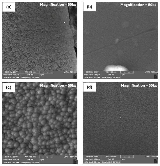
Figure 2.
SEM images showing the surface morphologies of the coatings deposited under various conditions: (a) eight Cr plugs at −30 V, (b) eight Cr plugs at −60 V, (c) four Cr plugs at −50 V, and (d) eight Cr plugs at −50 V.
3.3. Coating Cross-Section
Figure 3 presents high-magnification FE-SEM cross-sectional images of the coatings, revealing a distinct bilayer structure consisting of an adhesion interlayer and a dense top coating layer. The interlayer is primarily composed of a Cr-Al metallic phase, while the top layer comprises a CrAlN nitride coating. The interfacial adhesion layer was consistently observed to be approximately 0.5 μm thick. The nitride layer exhibited a dense and uniform microstructure across all samples, indicating consistent film growth and strong cohesive integrity. Under a fixed deposition duration of 1 h, the thickness of the top coating ranged from approximately 1.7 to 3.0 μm, varying primarily with the target configuration and, to a lesser extent, with the applied bias voltage. Specifically, for coatings deposited using the eight-Cr-plug target, the CrAlN layer thicknesses were approximately 2.8 μm, 2.8 μm, and 3.0 μm at bias voltages of −30 V, −50 V, and −60 V, respectively. In contrast, the coating produced using the four-Cr-plug target at −50 V exhibited a reduced thickness of around 1.8 μm. These results suggest that a higher Cr/Al surface ratio in the target may enhance the deposition rate, resulting in thicker coatings under identical deposition conditions.
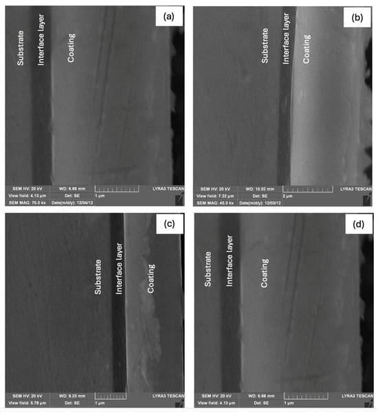
Figure 3.
Cross-sectional SEM images of the coatings, revealing the interface layer between the substrate and the bulk of the coating: (a) eight Cr plugs at −30 V, (b) eight Cr plugs at −60 V, (c) four Cr plugs at −50 V, and (d) eight Cr plugs at −50 V.
3.4. Hardness
Table 2 presents the hardness values (in GPa) for all coatings, measured using a micro-indentation tester. The reported values represent the average of five independent measurements. It is evident that the hardness of the CrAlN coatings increases significantly for a higher Cr/Al ratio in the target, which directly influences the Cr/Al content in the resulting coatings. Additionally, for a given target composition, increasing the substrate bias voltage results in a further enhancement of hardness. This improvement can be attributed to the combined effect of a higher concentration of heavier elements and elevated ion energies under increased biasing conditions. These factors contribute to greater film densification, elevated residual compressive stresses, and consequently, improved hardness. Similar trends have been reported in the literature, where the incorporation of Cr has been shown to influence stress development in CrAlN coatings [23] significantly.

Table 2.
Average hardness values and corresponding standard deviations of CrAlN coatings deposited under various conditions.
3.5. Scratch Resistance
Figure 4 displays the measured friction force (FF), friction coefficient (FC), and the corresponding applied loads for the CrAlN coatings. The critical loads and the calculated crack propagation resistance (CPR) values are summarized in Table 3. The lower critical load (Lc1) increased consistently with increasing the substrate bias voltage and was generally higher for coatings with a higher Cr/Al ratio. This is particularly evident when comparing the eight-Cr-plug and four-Cr-plug samples at the same bias voltage. In contrast, the upper critical load (Lc2) did not exhibit a strong dependence on bias voltage but showed a notable increase for the coating with the lower Cr/Al ratio. The calculated CPR values appear to correlate with the coating toughness and follow the commonly observed inverse relationship between toughness and hardness, reflecting the typical trade-off between these two mechanical properties.
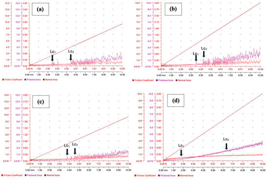
Figure 4.
Variation of friction force and friction coefficient with increasing normal load (0.03 N to 10 N) for CrAlN coatings deposited under different conditions: (a) eight Cr plugs at −30 V, (b) eight Cr plugs at −50 V, (c) eight Cr plugs at −60 V, and (d) four Cr plugs at −50 V.

Table 3.
Critical loads and calculated CPR for CrAlN coatings deposited under various conditions.
The panoramic micrographs of the scratch tracks are presented in Figure 5, while Figure 6 illustrates the formation of tensile cracks and lateral delamination along the crack edges in the CrAlN coatings. Coating delamination was more pronounced at higher bias voltages in samples deposited using the eight-Cr-plug target. Conversely, the coating with the lower Cr/Al ratio exhibited significantly improved resistance to delamination. As shown in Figure 5 and Figure 6, severe delamination was observed in the sample with eight Cr plugs at −50 V, particularly from the sides of the scratch track. In contrast, the sample deposited with four Cr plugs at −50 V showed no visible delamination along the scratch path, even at the highest applied load, indicating enhanced adhesion and cohesion.
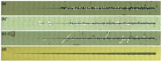
Figure 5.
Panoramic micrographs of scratch test tracks produced by a Rockwell diamond indenter (ID-170) under an increasing normal load from 0.03 N to 10 N: (a) eight Cr plugs at −30 V, (b) eight Cr plugs at −50 V, (c) eight Cr plugs at −60 V, and (d) four Cr plugs at −50 V.
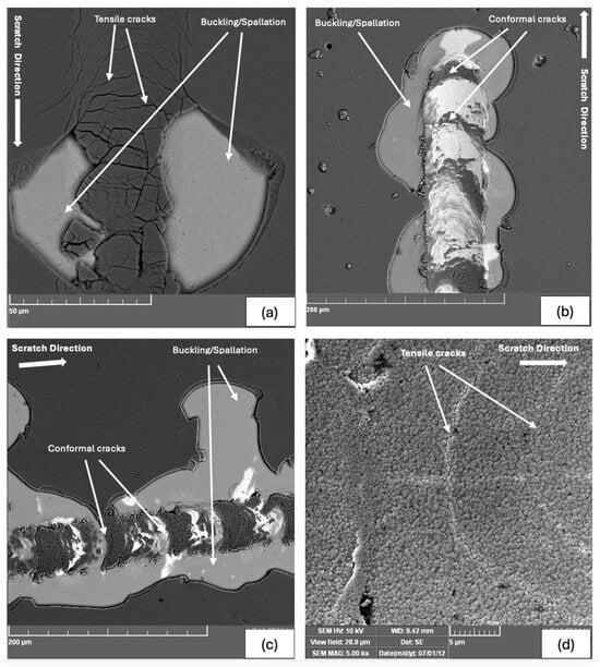
Figure 6.
Field emission SEM micrographs showing tensile cracks and lateral delamination along the crack edges in the CrAlN coatings: (a) eight Cr plugs at −30 V, (b) eight Cr plugs at −50 V, (c) eight Cr plugs at −60 V, and (d) four Cr plugs at −50 V.
Fluctuations in friction force and friction coefficient were more pronounced in the eight-Cr-plug sample deposited at −50 V compared to the four-Cr-plug sample under the same bias voltage. A similar variation in friction force was observed in all eight-Cr-plug coating samples produced at different bias voltages. Once coating detachment was initiated, it propagated along the entire scratch track. Notably, the sample deposited at −60 V exhibited higher initial friction coefficient amplitudes compared to the sample deposited at −30 V. This behavior may be attributed to the higher residual stresses induced during deposition at −60 V, resulting in greater stored energy release during scratch testing.
The indenter movement during a scratch test exerts compressive stress, which generates semi-circular cracks opening opposite to the indenter motion at the front edge of the indenter. These cracks are termed as conformal or compressive crack openings [23]. As shown in Figure 6, the eight-Cr-plugs target −30 V biased sample cracking mode is dominated by semi-circular crack traces parallel to the trailing edge of the indenter. Coating spallation and buckling were also observed. Surface buckling appears to increase with increasing biasing voltage. The spalling or buckling coating failure occurred due to a compressive stress field in front of the moving indenter. In the eight-Cr-plug samples deposited at −50 V and −60 V, the conformal cracking mode became more pronounced, accompanied by significant surface buckling. The extent of buckling was severe enough to cause branched cracking along the main scratch path, indicating a more brittle fracture behavior compared to the −30 V sample. Notably, such crack branching and extensive buckling were only observed in the −50 V and −60 V samples. In contrast, in the −30 V sample, buckling was limited and confined to the scratch track. For all eight-Cr-plug coatings, delamination initiated at the onset of failure and continued along the scratch track, demonstrating lower resistance to crack propagation.
In contrast, the coating deposited using the four-Cr-plug targets at −50 V exhibited a markedly different failure behavior, as shown in Figure 7. The dominant cracking mode was tensile or “backward” cracking, which originates from tensile stress fields at the trailing edge of the indenter [24]. These cracks indicate cohesive failure within the coating without material detachment, in contrast to the extensive spallation observed in the 8 Cr plug samples. The absence of surface buckling and trackside delamination in the 4 Cr plug sample suggests that the coating has improved toughness. Although similar tensile cracks were also observed in the 8 Cr plug sample at −30 V, coating spallation was evident in that case, further highlighting the superior resistance to cracking of the lower Cr/Al coating.
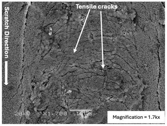
Figure 7.
SEM micrograph showing tensile cracks in the coating deposited using the four-Cr-plug target.
4. Conclusions
The main conclusions of this study can be summarized as follows:
- 1.
- All coatings exhibited a distinct bilayer structure, comprising an interlayer approximately 0.5 μm thick beneath the bulk CrAlN layer.
- 2.
- Microdroplets were more pronounced in the coating produced using the four-Cr-plug target, while both their size and density decreased with increasing bias voltage in coatings deposited with the eight-Cr-plug target.
- 3.
- Coating hardness increased with both higher Cr/Al ratios and elevated substrate bias voltages, likely due to enhanced densification and the development of residual compressive stresses.
- 4.
- The calculated crack propagation resistance (CPR), a qualitative indicator of coating toughness, was inversely proportional to the coating hardness. Higher CPR values were observed in coatings with a lower Cr/Al ratio and lower bias voltages.
- 5.
- Coating spallation and surface buckling were the dominant failure modes in coatings produced using the eight-Cr-plug target, with buckling severity increasing at higher bias voltages. In contrast, coatings deposited with the four Cr plug target exhibited limited delamination, indicating enhanced toughness and better adhesion.
Author Contributions
Conceptualization, Z.M.G.; methodology, Z.M.G. and S.A.; validation, Z.M.G.; formal analysis, S.A. and Z.M.G.; investigation, S.A.; resources, Z.M.G.; writing—original draft preparation, S.A. and Z.M.G.; writing—review and editing, Z.M.G., N.K.A. and A.N.; visualization, S.A., Z.M.G., N.K.A. and A.N.; supervision, Z.M.G. All authors have read and agreed to the published version of the manuscript.
Funding
This research received no external funding.
Data Availability Statement
The original contributions presented in this study are included in the article. Further inquiries can be directed to the corresponding author.
Acknowledgments
S. Alam gratefully acknowledges King Fahd University of Petroleum and Minerals (KFUPM, Dhahran, Saudi Arabia) for providing a full scholarship to pursue his M.S. thesis in the Department of Mechanical Engineering. The authors also extend their sincere appreciation to KFUPM for the institutional support and research facilities that made this work possible. Special thanks are due to the Institute for Aerospace Research, National Research Council, Ottawa, Canada, for synthesizing the target and coating samples during Z. Gasem’s sabbatical stay.
Conflicts of Interest
Author Shahnawaz Alam was employed by Al Yamamah Steel Industries Company. The remaining authors declare that the research was conducted in the absence of any commercial or financial relationships that could be construed as a potential conflict of interest.
References
- Caliskan, H.; Panjan, P.; Kurbanoglu, C. 3.16 Hard Coatings on Cutting Tools and Surface Finish. Compr. Mater. Finish. 2017, 3, 230–242. [Google Scholar] [CrossRef]
- De Araujo, P.; Steyer, P.; Millet, J.-P.; Damond, E.; Stauder, B.; Jacquot, P. PVD aluminium alloy coatings: Environmentally friendly alternative to protect steel parts against corrosion. Surf. Eng. 2003, 19, 304–309. [Google Scholar] [CrossRef]
- Baptista, A.; Silva, F.J.G.; Porteiro, J.; Míguez, J.L.; Pinto, G. Sputtering physical vapour deposition (PVD) coatings: A critical review on process improvement and market trend demands. Coatings 2018, 8, 402. [Google Scholar] [CrossRef]
- Inspektor, A.; Salvador, P.A. Architecture of PVD coatings for metalcutting applications: A review. Surf. Coat. Technol. 2014, 257, 138–153. [Google Scholar] [CrossRef]
- Bobzin, K. High-performance coatings for cutting tools. CIRP J. Manuf. Sci. Technol. 2017, 18, 1–9. [Google Scholar] [CrossRef]
- Sousa, V.F.C.; Silva, F.J.G. Recent advances on coated milling tool technology-a comprehensive review. Coatings 2020, 10, 235. [Google Scholar] [CrossRef]
- Vetter, J.; Eriksson, A.O.; Reiter, A.; Derflinger, V.; Kalss, W. Quo vadis: Alcr-based coatings in industrial applications. Coatings 2021, 11, 344. [Google Scholar] [CrossRef]
- He, Q.; DePaiva, J.M.; Kohlscheen, J.; Veldhuis, S.C. Analysis of the performance of PVD AlTiN coating with five different Al/Ti ratios during the high-speed turning of stainless steel 304 under dry and wet cooling conditions. Wear 2022, 492–493, 204213. [Google Scholar] [CrossRef]
- Bagcivan, N.; Bobzin, K.; Theiß, S. (Cr1−xAlx)N: A comparison of direct current, middle frequency pulsed and high power pulsed magnetron sputtering for injection molding components. Thin Solid Films 2013, 528, 180–186. [Google Scholar] [CrossRef]
- Sugishima, A.; Kajioka, H.; Makino, Y. Phase transition of pseudobinary Cr–Al–N films deposited by magnetron sputtering method. Surf. Coat. Technol. 1997, 97, 590–594. [Google Scholar] [CrossRef]
- Wang, Y.X.; Zhang, S.; Lee, J.-W.; Lew, W.S.; Li, B. Influence of bias voltage on the hardness and toughness of CrAlN coatings via magnetron sputtering. Surf. Coat. Technol. 2012, 206, 5103–5107. [Google Scholar] [CrossRef]
- Bobzin, K.; Lugscheider, E.; Nickel, R.; Bagcivan, N.; Krämer, A. Wear behavior of Cr1−xAlxN PVD-coatings in dry running conditions. Wear 2007, 263, 1274–1280. [Google Scholar] [CrossRef]
- Lv, Y.; Ji, L.; Liu, X.; Li, H.; Zhou, H.; Chen, J. Influence of substrate bias voltage on structure and properties of the CrAlN films deposited by unbalanced magnetron sputtering. Appl. Surf. Sci. 2012, 258, 3864–3870. [Google Scholar] [CrossRef]
- Tang, J.-F.; Lin, C.-Y.; Yang, F.-C.; Chang, C.-L. Influence of nitrogen content and bias voltage on residual stress and the tribological and mechanical properties of CrAlN films. Coatings 2020, 10, 546. [Google Scholar] [CrossRef]
- Hedenqvist, P.; Olsson, M.; Jacobson, S.; Söderberg, S. Failure mode analysis of TiN-coated high speed steel: In situ scratch adhesion testing in the scanning electron microscope. Surf. Coat. Technol. 1990, 41, 31–49. [Google Scholar] [CrossRef]
- ASTM C1624-05; Standard Test Method for Adhesion Strength and Mechanical Failure Modes of Ceramic Coatings by Quantitative Single Point Scratch Testing. ASTM International: West Conshohocken, PA, USA, 2010.
- Bull, S. Failure mode maps in the thin film scratch adhesion test. Tribol. Int. 1997, 30, 491–498. [Google Scholar] [CrossRef]
- Zhang, S.; Sun, D.; Fu, Y.; Du, H. Toughness measurement of thin films: A critical review. Surf. Coat. Technol. 2005, 198, 74–84. [Google Scholar] [CrossRef]
- Fox-Rabinovich, G.; Beake, B.; Endrino, J.; Veldhuis, S.; Parkinson, R.; Shuster, L.; Migranov, M. Effect of mechanical properties measured at room and elevated temperatures on the wear resistance of cutting tools with TiAlN and AlCrN coatings. Surf. Coat. Technol. 2006, 200, 5738–5742. [Google Scholar] [CrossRef]
- Steinmann, P.; Tardy, Y.; Hintermann, H. Adhesion testing by the scratch test method: The influence of intrinsic and extrinsic parameters on the critical load. Thin Solid Films 1987, 154, 333–349. [Google Scholar] [CrossRef]
- Arudi, I.S.; Hamzah, E.; Yajid, M.A.M.; Bushroa, A.; Munshi, S.M.; Al-Ashhab, M.; Ibrahim, M.Z. Taguchi optimization of hardness and scratch adhesion strength of multilayer Ti/TiN coatings on Ti-51 at%Ni alloy deposited via magnetron sputtering technique. J. Mater. Res. Technol. 2023, 27, 7664–7672. [Google Scholar] [CrossRef]
- Kuznetsova, T.; Lapitskaya, V.; Khabarava, A.; Chizhik, S.; Warcholinski, B.; Gilewicz, A.; Kuprin, A.; Aizikovich, S.; Mitrin, B. Effect of metallic or non-metallic element addition on surface topography and mechanical properties of crn coatings. Nanomaterials 2020, 10, 2361. [Google Scholar] [CrossRef] [PubMed]
- Pham, T.; Le Bourhis, E.; Goudeau, P.; Guérin, P. Residual stresses in AlCrN PVD thin films. EPJ Web Conf. 2010, 6, 26002. [Google Scholar] [CrossRef]
- Burnett, P.; Rickerby, D. The relationship between hardness and scratch adhesion. Thin Solid Films 1987, 154, 403–416. [Google Scholar] [CrossRef]
Disclaimer/Publisher’s Note: The statements, opinions and data contained in all publications are solely those of the individual author(s) and contributor(s) and not of MDPI and/or the editor(s). MDPI and/or the editor(s) disclaim responsibility for any injury to people or property resulting from any ideas, methods, instructions or products referred to in the content. |
© 2025 by the authors. Licensee MDPI, Basel, Switzerland. This article is an open access article distributed under the terms and conditions of the Creative Commons Attribution (CC BY) license (https://creativecommons.org/licenses/by/4.0/).