1. Introduction
Since the 1990s, global production systems have undergone significant transformations, primarily driven by fluctuating demand, increasing product variant complexity, and rapid technological advancements. These shifts have exposed the inefficiencies of traditional production approaches, such as Dedicated Manufacturing Systems (DMSs) and Flexible Manufacturing Systems (FMSs). In response to these challenges, Koren et al. [
1] in 1999 introduced the concept of Reconfigurable Manufacturing Systems (RMSs).
RMSs represent a paradigm shift, characterised by the ability to rapidly and cost-effectively modify system structures and resources to accommodate highly variable production requirements [
2]. This new generation of modular, integrated, scalable, customisable, convertible, and diagnosable systems excels at adapting to dynamic market demands. Unlike DMSs, which are optimised for high efficiency but lack flexibility, or FMSs, which face the opposite challenge, RMSs offer customised adaptability by targeting specific part families [
3]. RMSs encompasses elements such as reconfigurable machine tools, reconfigurable assembly machines, and Reconfigurable Inspection Machines (RIMs), each tailored to distinct manufacturing processes.
In the context of inspection, RIMs play a critical role in ensuring high product quality across different production batches [
4,
5]. Moving beyond traditional contact-based Coordinate Measurement Machines (CMMs), modern inspection systems increasingly incorporate contactless, Numerically Controlled (NC) mobile components (e.g., cameras), as part of the next generation of reconfigurable Vision Inspection Systems (VISs). These systems offer significantly greater speed and flexibility in reconfiguration [
6]. To be effective in reconfigurable contexts, both the hardware and software components of VISs must be designed in accordance with reconfigurable machine principles to enable rapid and cost-effective adaptation to diverse products.
Recent advancements have significantly enhanced the software-driven reconfigurability of VISs [
6], enabling the inspection of a wide range of products through adaptable software combined with setup-specific reconfigurable hardware. However, while software elements can often be applied flexibly across different products, hardware constraints continue to limit the adaptability of reconfigurable systems across a wide range of product families.
As noted by Lupi et al. [
7], various hardware solutions have been proposed over the past decades to enhance the flexibility of VISs, often involving robotic arms or multiple NC components. However, systematic guidelines or step-by-step frameworks to design and develop the most appropriate reconfigurable hardware setup for specific inspection tasks remain underdeveloped. Moreover, general-purpose architectures frequently require significant customisation to address individual application requirements effectively.
A notable gap is evident in the development of handling systems (HSs) used in VISs. These systems include reconfigurable or flexible hardware components essential for product fixturing and handling throughout inspection.
This paper aims to bridge this gap, which is further detailed and refined into specific Research Questions (RQs) in
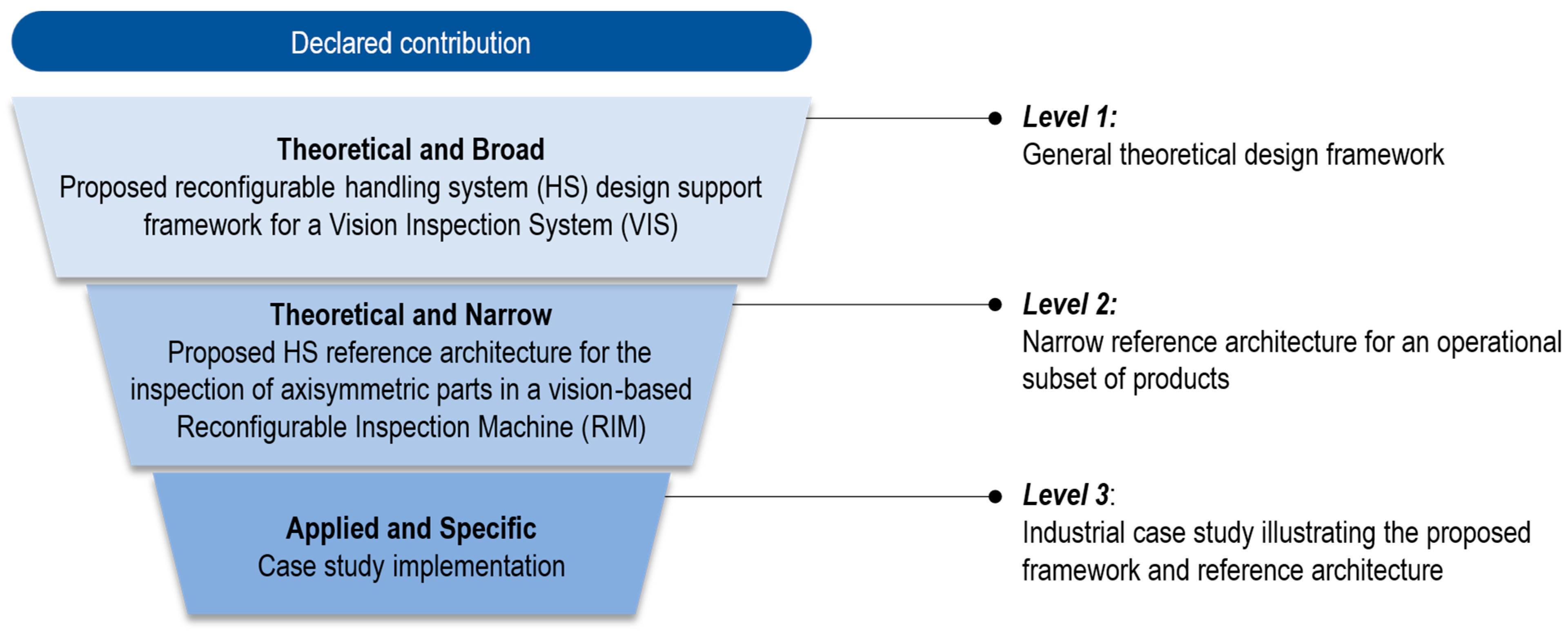
Section 2. The paper’s contributions are presented through the structured three-level funnel depicted in
Figure 1.
The first level (Level 1), which is theoretical and broad in scope, is addressed in
Section 3 and concerns the development of a novel design framework for the systematic design of the HS in a vision-based RIM. As part of this methodology, Model-Based Definition (MBD) is explored as a data management approach that embeds semantic information, including process parameters, within the 3D geometric description of the product. This integration aims to structure information in a machine-readable format, thereby enabling potential automation in data processing. The second level (Level 2), detailed in
Section 4, presents a general-purpose HS architecture for VIS inspection stations intended for axisymmetric parts, while the third level (Level 3), presented in
Section 5, consists of an industrial case study conducted in collaboration with a leading automotive manufacturer, serving as a practical implementation of the proposed framework and architecture.
Finally,
Section 6 provides a comprehensive discussion of the study’s outcomes, and
Section 7 concludes the paper by summarising key insights and outlining potential future directions.
2. Background
Handling components involves intricate tasks, wherein hardware elements responsible for positioning, fixturing, and stabilization are often custom-engineered to meet specific process or product requirements. As a result, changes in the products or processes often require inefficient and costly machine redesign or reconfiguration.
With increasing product variability and growing demand for customised production in low-volume batches, there is an urgent need for dynamic machinery capable of rapidly adapting its structure to evolving requirements. Reconfigurable machines have emerged as essential solutions, facilitating fast, cost-effective, and reliable reconfiguration. However, designing such machines requires careful consideration and integration of key principles underpinning reconfigurability [
3].
Focusing specifically on handling challenges within RIMs, HSs are pivotal in correctly orienting product features relative to inspection sensors. This often involves the integration of fixtures, rotary or linear axes, or robotic arms.
In the context of product inspection, contactless methods inherently offer greater flexibility compared to contact-based techniques. Machine vision-based systems have therefore undergone significant development and are increasingly employed for tasks such as part identification, assembly verification, and dimensional measurement, reflecting a significant market expansion [
8,
9].
According to Lupi et al. [
6], a general vision-based RIM architecture comprises five main subsystems (
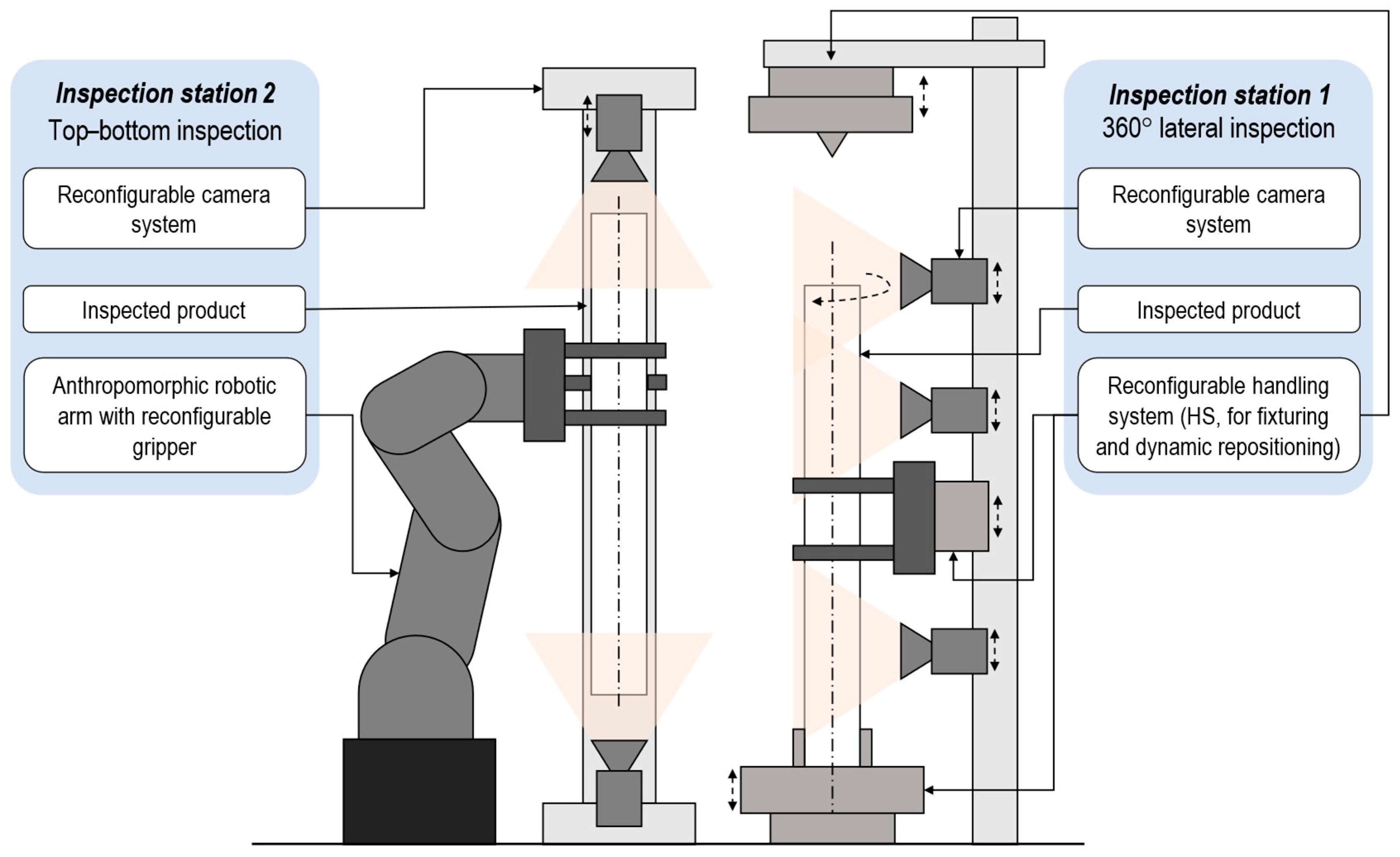
Figure 2): (1) a load and unload system; (2) an HS, which is further divided into (2.1) a fixturing system and (2.2) a motion system; (3) a lighting system; (4) a camera system; and (5) a vision data management system.
Despite its critical importance, the HS often receives insufficient attention in both the literature and system design. Moreover, the rigidity of current hardware configurations severely limits adaptability across diverse product variants, even where flexibility is achievable at the software level.
To effectively address the design challenges associated with the HS in vision-based RIMs,
Section 2.1 reviews existing flexible and reconfigurable HS solutions for VISs.
Section 2.2 outlines the core principles underpinning reconfigurability in RIMs, while
Section 2.3 provides the background on reconfigurable fixturing components.
Section 2.4 introduces the MBD approach for enriching 3D CAD models with semantic information. Finally,
Section 2.5 summarises the identified research gaps and presents the RQs addressed in this paper.
2.1. Handling Products Within a Vision-Based RIM
Despite the reduced constraints on product manipulation compared to contact-based inspection methods, handling a product within a vision-based RIM still presents key challenges to achieving true hardware flexibility. Two primary solution classes have traditionally been adopted to address this need [
7]: (i) multi-axis vision systems based on NC modules and (ii) robotic systems employing six Degrees of Freedom (6-DoF) robotic arms arranged in an eye-in-hand configuration. A detailed analysis of these approaches is crucial to understanding how flexibility is implemented at the HS level, with a focus on small- and mid-sized industrial products. Large-scale solutions, such as mobile climbing robots [
10], are beyond the scope of this discussion.
Various patented NC-based solutions have been developed to enhance inspection coverage by repositioning platforms, cameras, and lighting systems. Early configurations relied on manual setup and adjustments [
11,
12], while subsequent developments integrated software-driven repositionable NC modules [
13,
14,
15]. These solutions provided rapid and precise adaptability to different product geometries without extensive reconfiguration time. However, they generally maintained a static product position during inspection, relying solely on relative movements between sensor and product. As a result, the visibility of occluded or geometrically complex features remained limited, and fully dynamic product manipulation capabilities (i.e., those provided by the handling system) were lacking.
A notable advancement was proposed in patent CN106334678A [
16], featuring cameras mounted on an annular guide rail synchronised with an NC-driven rotating platform to enable sensor-product relative movements. Although this solution facilitated simultaneous multi-angle imaging, its capability for complete product manipulation remained limited. Consequently, manual repositioning was required between acquisition steps, thereby limiting the potential for full automation.
Expanding upon this concept, Loo et al. [
17] introduced a turret-based inspection system utilising multiple fixed vision modules (top, bottom, lateral) combined with NC-driven product rotation. This configuration significantly improved inspection coverage, allowing multiple viewing perspectives without manual intervention. However, its product-specific hardware configuration constrained broader applicability and reduced flexibility across diverse product families.
A more recent, yet still widely adopted, approach involves the use of anthropomorphic robotic arms with 6-DoF, extending motion capabilities beyond conventional NC systems. Typically configured in an eye-in-hand arrangement, these robots manipulate cameras around a stationary product, following predefined trajectories to ensure comprehensive surface coverage [
18,
19,
20,
21]. Despite enhanced flexibility, access to bottom or occluded surfaces remains restricted unless the products themselves are repositioned.
Hybrid solutions have emerged to overcome such limitations, integrating robotic arms with NC-driven rotary or flipping platforms [
22], secondary robotic manipulators for dynamic product repositioning [
22], or motorised conveyors extending the system reach [
23]. One of the most versatile hybrid architectures proposed in the literature deployed two collaborative robotic arms, one dedicated to inspection and the other to product handling, thereby ensuring fully automated coverage of complex geometries and hidden features [
22,
23].
Despite these technological advances, both NC-driven and robot-based implementations continue to exhibit significant limitations regarding adaptability, as design decisions (e.g., axis configuration, robot type, gripper compatibility) remain heavily dependent on product-specific characteristics. Consequently, designers must extensively tailor each HS solution to the specific requirements of individual inspection scenarios.
To address the absence of a universally applicable design framework for HSs from the hardware perspective, this paper proposes a structured methodology for the systematic development of HS architectures within vision-based RIM contexts, referencing the state of the art in RIM design principles (
Section 2.2) and reconfigurable fixture design (
Section 2.3).
From a software perspective, although better suited to reconfigurable solutions, current approaches often exhibit limited adaptability, frequently requiring low-level manual reprogramming (e.g., for robot trajectories) for each product variant. Recent studies have demonstrated that embedding configuration parameters into 3D product models can facilitate automated system reconfiguration [
21]. In alignment with this trend, the present work integrates MBD (
Section 2.4) to structure and formalise product and process information in a machine-readable format, thereby paving the way for future development of fully automated, software-guided reconfiguration processes.
2.2. Vision-Based RIM
RIMs were initially conceptualised in the early 2000s, notably through a pivotal patent filed by Koren et al. [
24]. Subsequently, foundational contributions by researchers such as Katz et al. [
3] and Barhak et al. [
25] significantly advanced RIM technologies, particularly for rapid in-process inspection of machined features within specific part families (e.g., cylinder heads). Early applications of RIMs primarily focused on surface analysis; defect detection, including porosity and texture anomalies; and broader quality control tasks. Further progress was achieved by Garcia et al. [
26], who introduced a general framework aimed at automating the reconfiguration of VIS algorithms.
Recent developments, notably those integrating Artificial Intelligence (AI)-based fault detection, adaptive sensing technologies, and modular hardware–software architectures, have positioned RIMs as critical enablers within Industry 4.0 quality assurance frameworks [
5]. For instance, Vlatković et al. [
27] presented an RIM architecture specifically tailored to non-contact inspection in crosswire welding applications, highlighting the role of VISs in dynamic, highly variable manufacturing environments.
Within this evolving landscape, vision-based RIMs have emerged as particularly advantageous, offering rapid, cost-effective reconfigurability. This attribute is crucial in contemporary production scenarios characterised by frequent product changes that necessitate a minimal reconfiguration time, reduced manual intervention, and simplified deployment with low-code programming [
21,
28,
29].
However, the existing literature on RMSs has predominantly focused on production and tooling aspects, often overlooking the specific challenges associated with inspection processes [
5]. Moreover, there remains a notable scarcity of documented sources addressing this gap [
4].
Effective RIM design within the broader context of RMSs demands flexible and reconfigurable hardware and software architectures, guided by established RMS design principles [
3]. These include the following:
- (i)
Design for a specific family: ensuring specialised adaptability rather than generic flexibility.
- (ii)
Customised flexibility: providing support exclusively for product-specific variations, unlike general-purpose CMMs.
- (iii)
Rapid convertibility: enabling swift substitution or adjustments of modular components.
- (iv)
Scalability: facilitating the addition or removal of elements to dynamically meet throughput or functionality requirements.
- (v)
Distributed deployment: allowing the same RIM unit to be effectively adapted and utilised at multiple production locations.
- (vi)
Modularity: employing standardised, interchangeable building blocks to promote efficient and cost-effective reconfiguration.
Typically, designing an RIM begins with defining a general, modular architecture. The subsequent steps involve developing configuration options tailored to specific product variants.
To facilitate systematic RIM implementation, Gupta et al. [
4] proposed a comprehensive taxonomy categorising RIM into five distinct dimensions as follows:
- D1.
Components: differentiating physical elements (sensors, fixtures) from cyber elements (processing and control units).
- D2.
Measurement types: identifying specific inspection modalities (e.g., dimensional control).
- D3.
Design features: encompassing the design principles followed (e.g., modularity, convertibility, scalability).
- D4.
Inspection methodology: referring to the type of inspection (e.g., laser-based, vision-based, or hybrid).
- D5.
Nature of inspection: in-line, on-machine, or off-line.
In alignment with this five-dimension classification, this work introduces a dedicated RIM design framework and hardware architecture centred on the physical components (D1), with particular emphasis on the handling system (HS). Regarding measurement types (D2), by leveraging the versatility of vision-based inspection methods, the proposed framework imposes no restrictions on the types of inspections that can be performed. Furthermore, it rigorously adheres to the established RMSs principles outlined by Katz et al. [
3] (D3), thereby supporting flexible deployment across various operational vision-based inspection contexts (D4), including in-line, on-machine, and off-line configurations (D5).
2.3. Reconfigurable Fixtures and Fixture Design
Fixtures are essential tools in manufacturing systems, enabling accurate and repeatable positioning and orientation of parts. A well-designed fixture enhances product quality, reduces production time and costs, and improves overall process consistency. Conversely, poorly designed fixtures can significantly compromise manufacturing efficiency, with defect rates reaching up to 40% due to dimensional inaccuracies [
30,
31,
32].
Fixtures serve two primary functions: locating, which constrains the DoF of a part [
33], and clamping, which secures the part during processing [
30,
34]. Additional functions include vibration suppression, deformation control, and thermal management [
31].
With the shift toward small-batch, mass-customised production, traditional dedicated fixtures, characterised by high manufacturing costs and limited flexibility, have become increasingly unsuitable [
30]. In response, modern RMSs are progressively adopting flexible and reconfigurable fixtures, which can accommodate a broader variety of products through automatic or autonomous reconfiguration.
While dedicated fixtures are optimised for specific parts, flexible fixtures, such as modular and conformable ones, are designed to support multiple product variants [
35,
36]. Reconfigurable fixtures offer balanced solutions, efficiently managing variation within a single product family while reducing costs and reconfiguration effort compared to fully flexible alternatives [
37].
Within this context, Automated Fixtures (AFs) [
38], including both Automated Reconfigurable Fixtures (ARFs) and Automated Flexible Fixtures (AFFs), have emerged as a promising solution. These systems feature self-configuration capabilities that enable adaptability across production cycles with minimal or no human intervention for setup and adjustment [
39]. AFs can be categorised into several types based on their physical working principles and structural characteristics [
40], including box-joint-type [
41,
42], column-type [
43,
44], and robotic-type systems [
45,
46]. These technologies are increasingly being explored beyond machining, including welding [
47], metal forming [
48], and aerospace sector applications [
49,
50,
51].
From a design perspective, Computer-Aided Fixture Design (CAFD) systems aim to streamline fixture development by integrating traditional fixture design (FD) with CAD/CAM environments [
52]. CAFD typically follows a structured workflow consisting of four primary phases: (i) defining the setup characteristics; (ii) specifying the fixturing requirements; (iii) detailed unit design of individual fixture elements; and (iv) fixture verification, ensuring compliance with operational and functional constraints [
30].
Within the broader framework of HS design for vision-based RIMs, reconfigurable fixtures emerge as foundational enablers. These fixtures, serving as the mechanical interface between the product and system, must adapt to a wide spectrum of part geometries and inspection requirements. As such, fostering the development and integration of AFs, including both ARFs and AFFs, is essential for achieving high levels of adaptability and automation in HS design. This concept naturally extends to other functional appendages of the system, such as robotic grippers on 6-DoF manipulators, where similar reconfiguration principles must be applied to ensure versatile handling.
2.4. Model-Based Definition
In recent decades, Computer-Aided Design (CAD) models have become indispensable in manufacturing due to their capability to encapsulate detailed geometric and design-related data, thereby supporting numerous engineering and design activities [
53]. Their widespread adoption has extended their role beyond traditional geometric representation. More recently, CAD models have undergone a transformative evolution within the MBD paradigm [
54], which seeks to embed both geometric and semantic information directly within the 3D CAD model, with the aim of realising the long-sought digital thread. This approach enables streamlined communication of process, product, and Product Lifecycle Management (PLM) data through a single source of truth (i.e., the CAD model itself) [
53,
55].
The semantic content embedded in MBD-enriched 3D models is formally referred to as Product Manufacturing Information (PMI), in accordance with international standards such as ASME Y14.47:2023 [
56] and ISO 10303-242:2022 [
57]. Among the various PMI elements, Geometric Dimensioning and Tolerancing (GD&T) is particularly prominent, especially in machining applications, due to its ability to define dimensional constraints and tolerances in a machine-readable format.
Recent studies, however, have demonstrated the potential of using PMI in a broader range of manufacturing tasks as a means to convey reconfiguration instructions and parameters, including those related to inspection [
28,
58], assembly [
59,
60], and welding [
61].
In the specific context of vision-based inspection systems, Lupi et al. [
6] introduced a Flexible Vision Inspection System (FVIS) framework that incorporates reprogrammable hardware components (i.e., cameras mounted on NC axes). These software-controlled components are integrated into a reconfigurable architecture that supports offline programming by leveraging real images, CAD models, and synthetic images of the product under inspection. Leveraging the MBD paradigm, the hardware and software components of such vision systems can be systematically reconfigured, enabling rapid system adaptation and minimal downtime [
21].
Extending this approach, the current study specifically explores MBD-driven design for the HS within vision-based inspection environments. By systematically structuring and embedding critical HS-related semantic information into the 3D product model, this research lays the groundwork for future software-guided reconfiguration of the HS.
2.5. Research Questions
The analysis of the domains explored in the previous sections reveals several interconnected research gaps, leading to the formulation of two primary RQs as follows:
RQ1: How can the design process of the handling system (HS) within vision-based Reconfigurable Inspection Machines (RIMs) be systematically structured?
This question highlights the need for a step-by-step, generic design methodology that guides engineers through the identification of design requirements, component selection, integration, and configuration validation, while integrating expert knowledge and CAFD systems and techniques.
RQ2: Which general-purpose hardware reference architecture can support the design of the handling system (HS) in vision-based Reconfigurable Inspection Machines (RIMs) for the inspection of a broad family of axisymmetric components?
This question focuses on the development of a modular and adaptable hardware reference architecture that integrates NC axes and 6-DoF robotic manipulators. By targeting a specific family of products (i.e., axisymmetric parts), commonly adopted in manufacturing sectors such as automotive and aerospace (e.g., half-shafts, motor shafts, pistons), the proposed architecture aims to reduce design complexity and enable rapid reconfiguration, particularly when used in conjunction with the design framework introduced in RQ1.
Finally, this paper illustrates the practical application of the proposed design support framework (RQ1) and the general-purpose hardware architecture (RQ2) through an industrial case study featuring an automated visual inspection cell for half-shafts. The system was jointly developed by the Department of Civil and Industrial Engineering (DICI) at the University of Pisa in collaboration with GKN Driveline in Florence. It was designed to inspect surface and texture defects, assembly or alignment errors, and dimensional deviations, demonstrating the tangible benefits of transitioning from manual inspection to an automated and reconfigurable solution.
3. The Proposed Design Support Framework
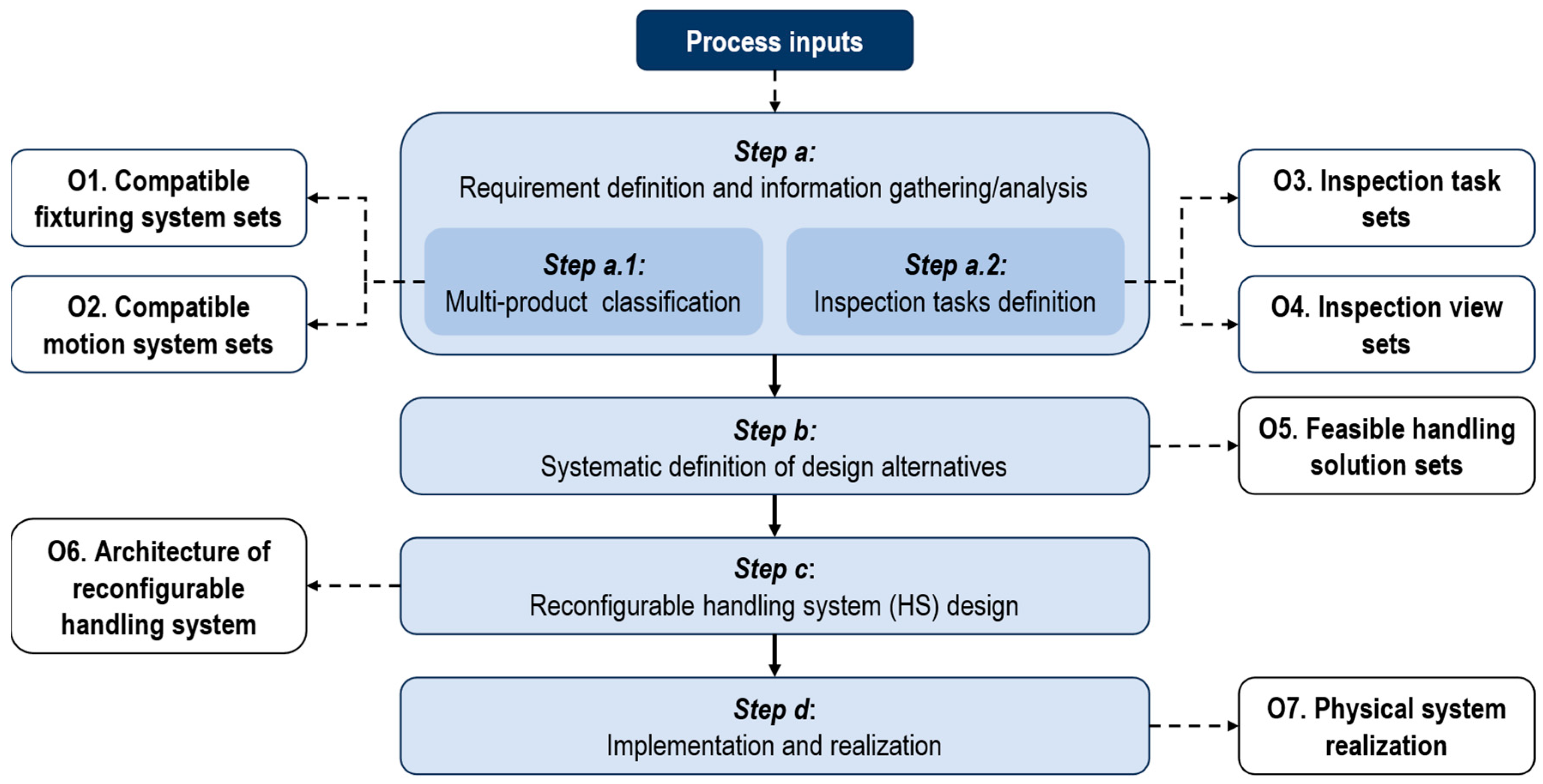
The proposed reconfigurable HS design support framework for the VIS follows a systematic four-step methodology. The overall workflow is illustrated in
Figure 3 and detailed in the following.
Step a: requirement definition and information gathering/analysis (
Section 3.1). This step involves collecting and organising all necessary information by examining existing documentation related to the products under inspection (e.g., technical drawings, CAD models, MBD semantic annotations) and identifying any missing data. The gathered information must be systematically structured to ensure quick access, completeness, and ease of retrieval in the subsequent design phases.
Step b: systematic definition of design alternatives (
Section 3.2). Building on the data extracted in
Step a, traditional CAFD methods are applied to define feasible solutions for fixturing and motion of each product variant during the inspection task. Beyond conventional FD, the proposed methodology also considers object motion strategies, recognising that in this context “fixtures” must not only locate, clamp, and support the product but may also reposition it to enable inspection tasks. At this stage, explicit considerations of reconfigurability are not yet addressed.
Step c: reconfigurable HS design (
Section 3.3). Using the design alternatives developed in
Step b, the process converges on a unified, reconfigurable HS that strictly adheres to the RIM design principles defined in
Section 2.2. The objective is to achieve rapid and cost-effective adaptability to different product variants within the same family, while ensuring consistent inspection performance and reliability.
Step d: implementation and integration (
Section 3.4). In the final phase, the detailed engineering, manufacturing, and physical integration of the HS into the inspection station are carried out. This includes both functional and mechanical integration, ensuring that all system components operate cohesively within the vision-based RIM architecture.
3.1. Step a: Requirement Definition and Information Gathering/Analysis
The workflow for
Step a is illustrated at the top of
Figure 3. The initial task consists of defining the problem and specifying the design requirements. Traditionally, this information is embedded in technical drawings, process sheets, or machine specifications. However, much of it can now be extracted directly from enriched CAD models by adopting MBD strategies. This approach improves documentation efficiency, reduces data duplication, and facilitates the use of machine-readable information, enabling advanced Levels of Automation (LoA). Additional considerations include available assets, operational constraints, and production throughput requirements.
Step a is divided into two sub-steps: multi-product classification (Step a.1) and inspection task definition (Step a.2).
3.1.1. Step a.1: Multi-Product Classification
This process involves extracting all relevant information for each product from primary inputs (e.g., CAD models) and assessing the availability of assets suitable for inspecting the specific product. In line with CAFD principles [
34], key product data include the following:
Material properties, weight, major dimensions, and geometry (e.g., diameter, length).
Structural features (e.g., number of parts, connection types, DoF, symmetry).
Orientation constraints (e.g., horizontal or vertical placement).
Surface finishing, surfaces requiring special protection (e.g., threaded or delicate areas), and surfaces suitable for fixture placement or mechanical actuation.
Personnel and equipment information, including available resources, operational constraints, and production throughput targets.
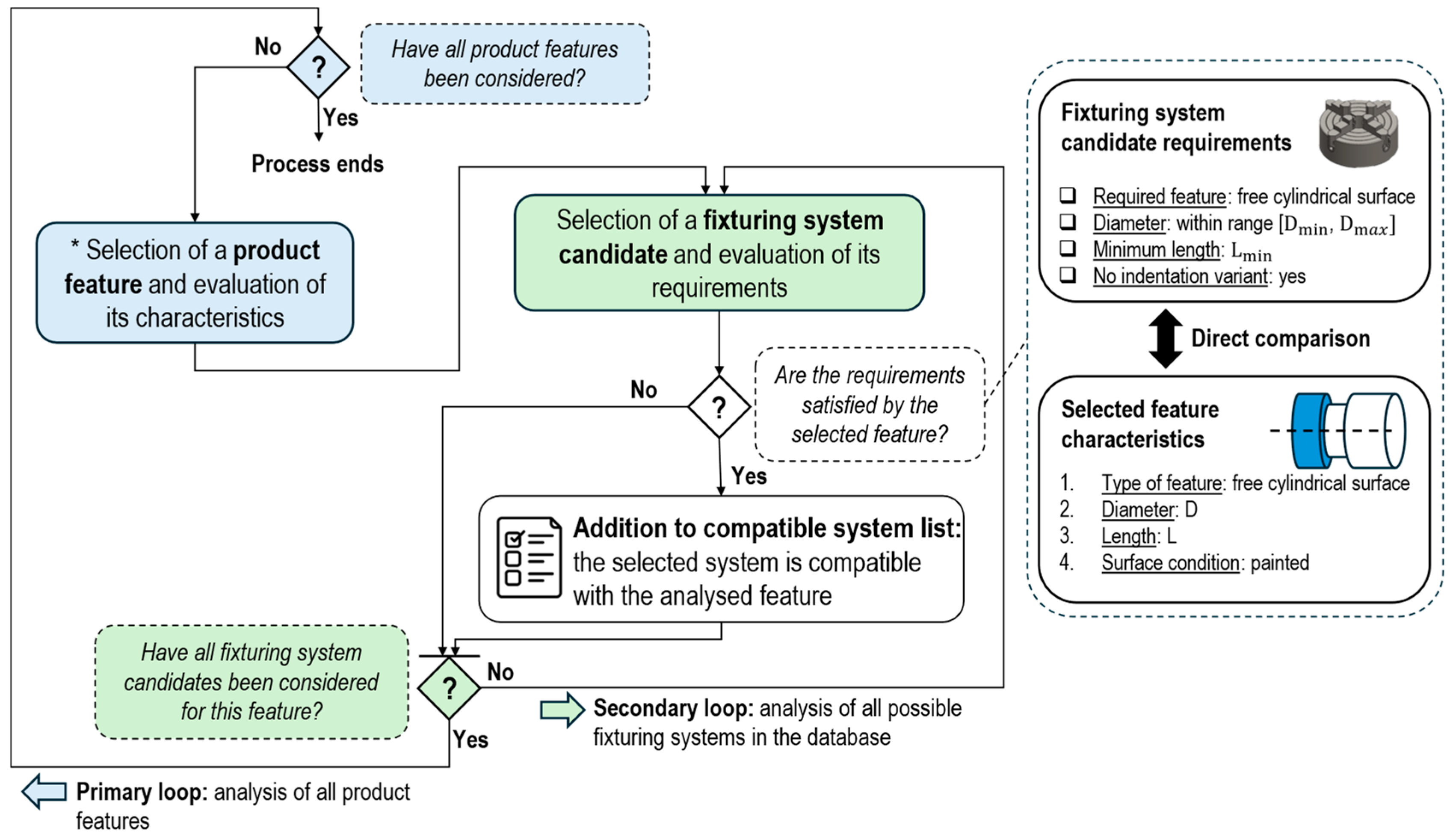
All of these data are systematically processed to identify, for each product variant, both the compatible fixturing and motion systems and the product features capable of accommodating them. The process for defining all applicable system feature combinations is illustrated in
Figure 4 for a generic fixture.
The evaluation process begins by selecting a product feature and comparing its key characteristics with the requirements of each fixturing system stored in the library (i.e., the secondary loop, shown as light green boxes in
Figure 4). The aim is to identify compatible fixturing options to be added to the fixturing system set by matching the feature’s attributes with the constraints and capabilities of the available systems. The key factors considered in this matching include the surface or feature type (e.g., cylindrical versus flat), dimensional constraints (e.g., allowable diameter or width), material compatibility (e.g., need for anti-indentation or scratch protection), and preferred orientation relative to gravity (e.g., horizontal or vertical). This process is repeated for each product feature as part of the primary loop (shown in light blue).
A similar approach is applied to the definition of the set of compatible motion systems, ensuring that each candidate feature is evaluated against the relevant requirements of potential motion mechanisms. When MBD is employed, this entire extraction and matching process can be automated using rule-based or AI-driven methods, leveraging the machine-readable capabilities of PMI.
The matching process is repeated for each product variant under investigation, and the resulting outcomes are categorised into two main output classes:
O1: compatible fixturing system sets. These detail, for each product variant, the surfaces suitable for locating, clamping, and supporting the product, along with their compatible fixturing systems.
O2: compatible motion system sets. These detail, for each product variant, the surfaces suitable for motion and handling, along with their compatible motion systems.
3.1.2. Step a.2: Inspection Task Definition
This sub-step identifies all product features that require inspection and defines the relevant parameters, such as the feature location, inspection type (e.g., presence or absence, dimensional checks), and inspection-specific constraints. It also specifies the required camera positions and orientations for each feature, including the Region of Interest (RoI) coverage details (e.g., whether single or multiple viewpoints are needed to fully inspect the feature).
The data collected in this step are organised into two output classes:
O3: inspection task sets. These detail, for each product variant, all quality control tasks associated with individual product features. These include the locations of the controllable features and their corresponding inspection types.
O4: inspection view sets. These detail, for each product variant, all required images for inspecting each feature, including camera positions, orientations, and the number of frames necessary to ensure full inspection coverage. This information is derived from O3, taking into account product-specific geometric constraints (e.g., occlusions).
Similarly to the previous steps, when MBD is employed, all data collected or generated during Step a, including both inputs and outputs (O1–O4), can be stored directly within the CAD model in accordance with the semantic enrichment of 3D models.
3.2. Step b: Systematic Definition of Design Alternatives
In Step b, the objective is to filter the set of compatible fixturing and motion systems identified in Step a (O1–O2) in order to define subsets of alternative handling solutions suitable for the inspection of each product variant.
While outputs O1 and O2 define the potential physical handling systems applicable to the product, based solely on physical compatibility, they do not consider key factors such as total DoF, equilibrium, or static and dynamic constraints. Step b addresses these limitations by combining appropriate subsets of the identified systems to ensure proper handling of the product, taking into account both mechanical stability and the inspection-specific criteria defined in O3 and O4.
The outcome of this step is the class of O5 outputs (namely, feasible handling solution sets), which represents the set of viable HS configurations for each product variant within the inspected product family. These configurations consist of specific combinations of fixturing and motion systems.
Although structured data can be extracted from O1–O4, particularly when MBD is used to support automated retrieval, a fully automated CAFD process, as discussed in
Section 2.3, is not yet available. Consequently, expert judgement remains essential in the iterative design process, especially when identifying suitable reference surfaces for locating, supporting, clamping, or actuating the product. Moreover, the majority of the CAFD literature focuses on dedicated machining fixtures.
To address the above issues in adopting CAFD for visual inspection, the authors analysed the six fixture requirements derived from prior machining studies [
30,
62] and compared them to the needs of vision-based inspection, as summarised in
Table 1. Additional considerations are encouraged, such as positioning HS components to avoid occluding critical inspection features and prioritising isostatic solutions, which simplify design decisions, reduce the risk of misalignment, and minimise the need for additional regulation and adjustment.
Although a fully automated CAFD system remains beyond the scope of this work, the structured approach established in Step a enables more effective organisation of essential data for subsequent processing automation. By the end of Step b, all viable HS configurations (O5) are compiled for each product. Since O5 is a subset of O1 and O2, it can also be stored within the CAD model, reinforcing the MBD-enabled digital thread (i.e., the MBD dataset).
3.3. Step c: Reconfigurable Handling System Design
In this phase, products are grouped into families by comparing their respective O5 outputs. Components within the same family are handled by a common reconfigurable HS, adapted through configuration changes when necessary. Products within the same sub-family may even share an identical HS configuration. These grouping criteria may differ from those used in traditional machining contexts, as visual inspection introduces process-specific constraints that can lead to different family classifications.
Moreover, the analysis of O5 data informs the definition of the reconfigurable HS elements, including their types, positioning span, and range of motion, each essential for accommodating product variations during reconfiguration.
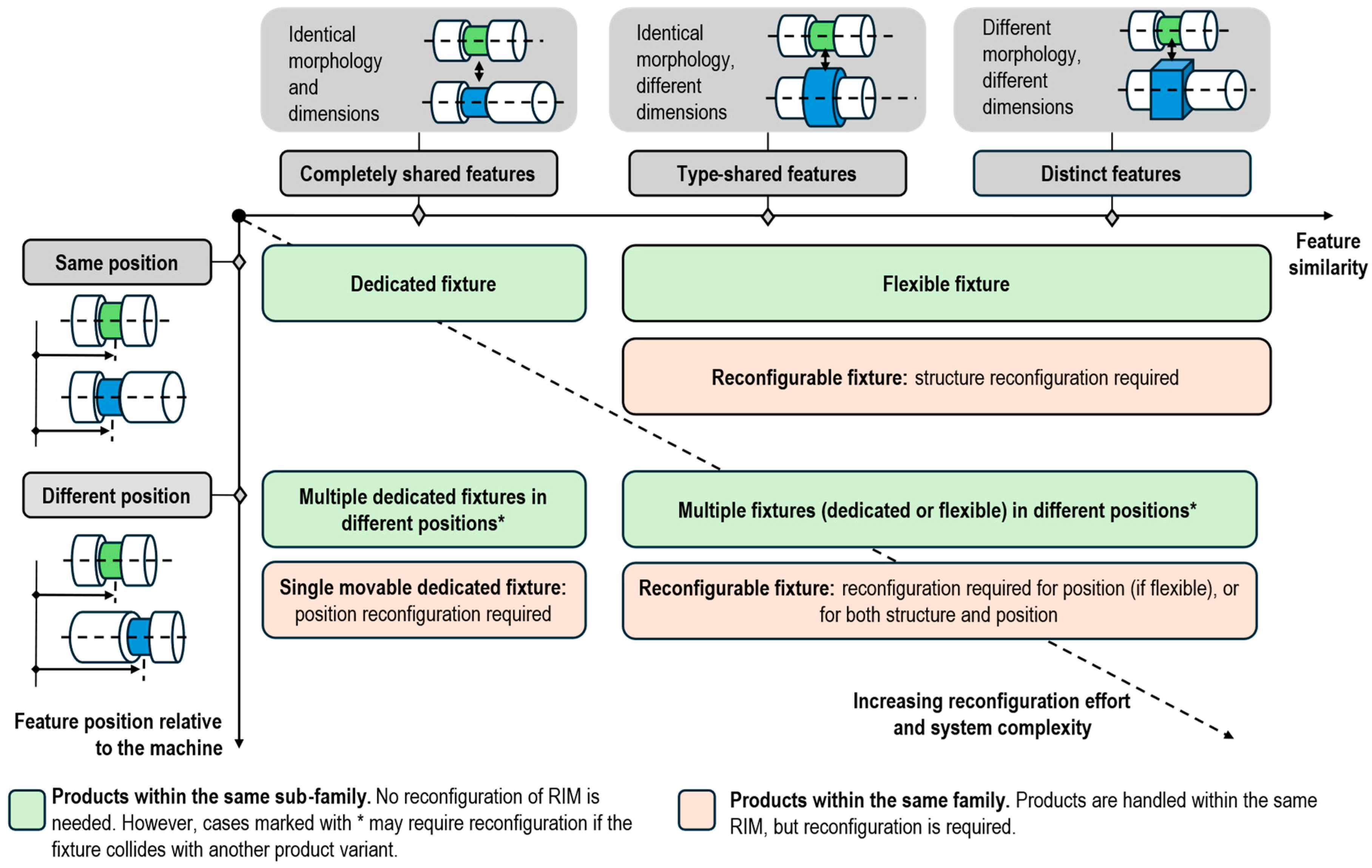
Figure 5 presents six representative scenarios based on the similarity and spatial positioning of handling features (i.e., the features used to apply fixturing or motion systems). Each scenario corresponds to a specific family grouping strategy and suggests an appropriate fixture type (e.g., dedicated, flexible, or reconfigurable). Parts may exhibit different levels of feature sharing, including:
Fully shared features, with identical morphology and dimensions (i.e., the “completely shared features” case in
Figure 5).
Partially shared features, with similar morphology but differing dimensions (i.e., the “type-shared features” case).
No shared features, differing in both morphology and dimensions (i.e., the “distinct features” case).
In addition, the position of handling features may vary or coincide across product variants, relative to a common coordinate system or reference datum. These aspects influence the family grouping logic and help determine the extent of reconfiguration required within the HS.
Scenarios located in the top-left region of
Figure 5 require minimal reconfiguration, whereas those in the bottom-right involve greater complexity in system adaptation. In these more demanding cases, reconfigurable fixtures may require modifications to the fixture structure, the positioning of individual elements, or both.
Ultimately, Step c produces O6, the conceptual architecture of the reconfigurable HS, designed to accommodate a range of product families and configurations through the use of modular and adaptable elements.
3.4. Step d: Implementation and Integration
In Step d, the system designed in the previous steps is physically implemented in accordance with RMS and RIM principles. O7 represents the physical realisation of the reconfigurable HS.
4. The Proposed Reference Architecture
The design support framework introduced in
Section 3 is intentionally broad and can be applied independently of the specific product under consideration. However, while
Step a can be easily automated, particularly through the use of MBD and rule-based techniques, the subsequent steps require more advanced, expert-driven reasoning, including equilibrium analyses, static considerations, and insights drawn from past project experience.
To support these tasks and address RQ2, this paper proposes, as an additional contribution (Level 2,
Figure 1), a general HS reference architecture specifically tailored for the inspection of axisymmetric products in a vision-based RIM (
Figure 6), along with detailed information on the corresponding HS (
Figure 7). This approach simplifies the design process and enables partial automation of
Step b and
Step c. It also builds on the general architectures discussed in the literature (
Section 2.1), combining NC components with a 6-DoF robotic arm.
4.1. Overall Architecture
The proposed reconfigurable HS is designed to handle families of axisymmetric products within a vision-based RIM, including both rigid and articulated types (i.e., with internal DoF). However, the architecture can be generalised and adapted to non-axisymmetric products by redefining the axis of rotation as a product-specific reference axis.
Figure 6 illustrates the overall hardware configuration of the vision-based RIM. The system employs multiple vision cameras, each mounted on NC modules. During inspection, the cameras remain stationary to avoid vibrations and simplify control, while the product is repositioned or rotated to expose all relevant features. However, during reconfiguration, both the camera and lighting systems can be repositioned via NC modules, enabling the station to adapt to different product families or part variants. The detailed design of the camera and lighting systems is beyond the scope of this paper.
To achieve full visual coverage, the proposed architecture incorporates two distinct inspection stations (
Figure 6), each dedicated to a specific task:
Inspection station 1 (detailed in
Section 4.2) performs 360° lateral surface inspection along the product’s axis of symmetry.
Inspection station 2 (detailed in
Section 4.3) captures top and bottom views, orthogonal to the axis of rotation.
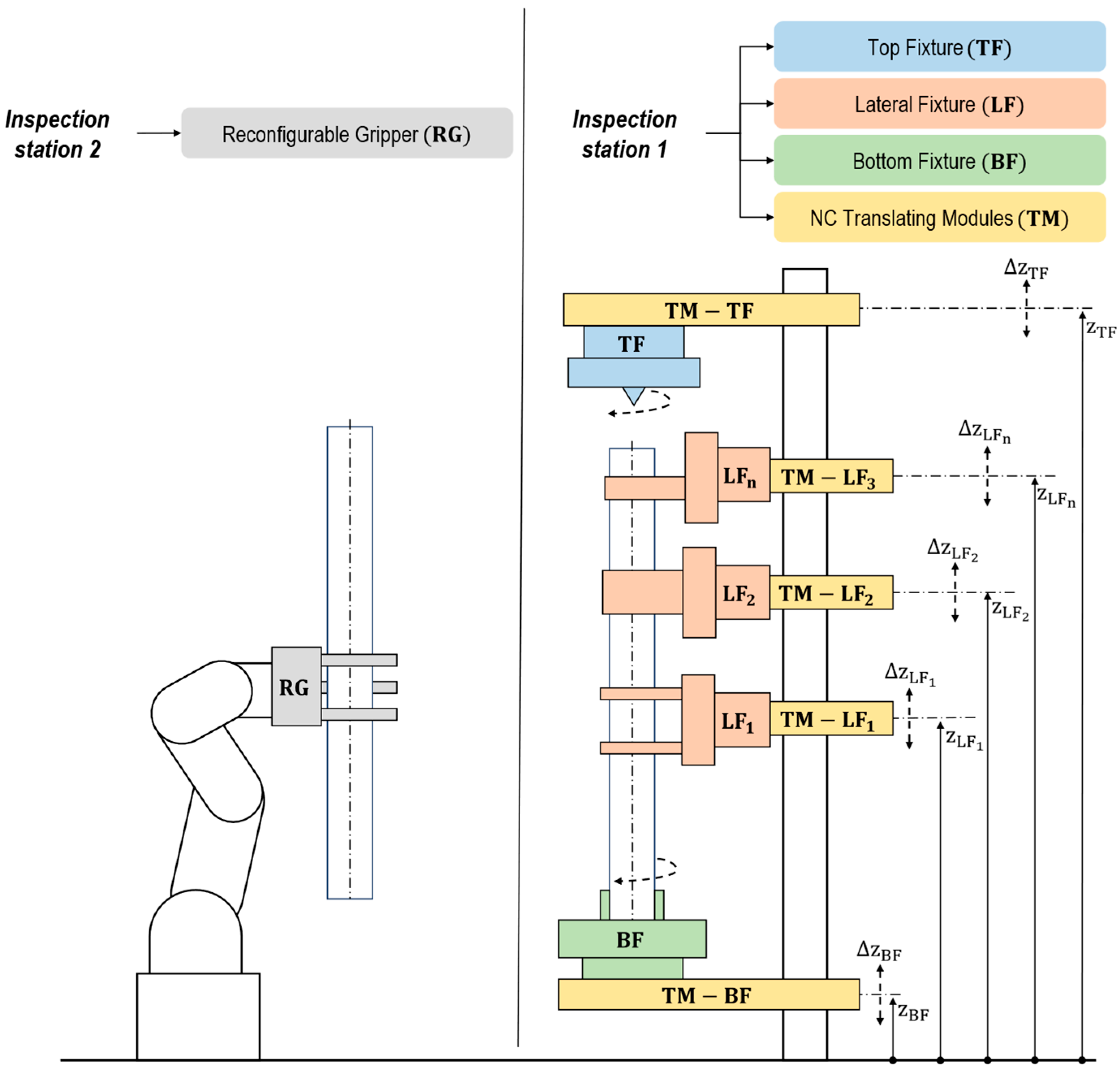
Together, these stations ensure the inspection of all relevant features. The generalised configuration of the HS is shown in
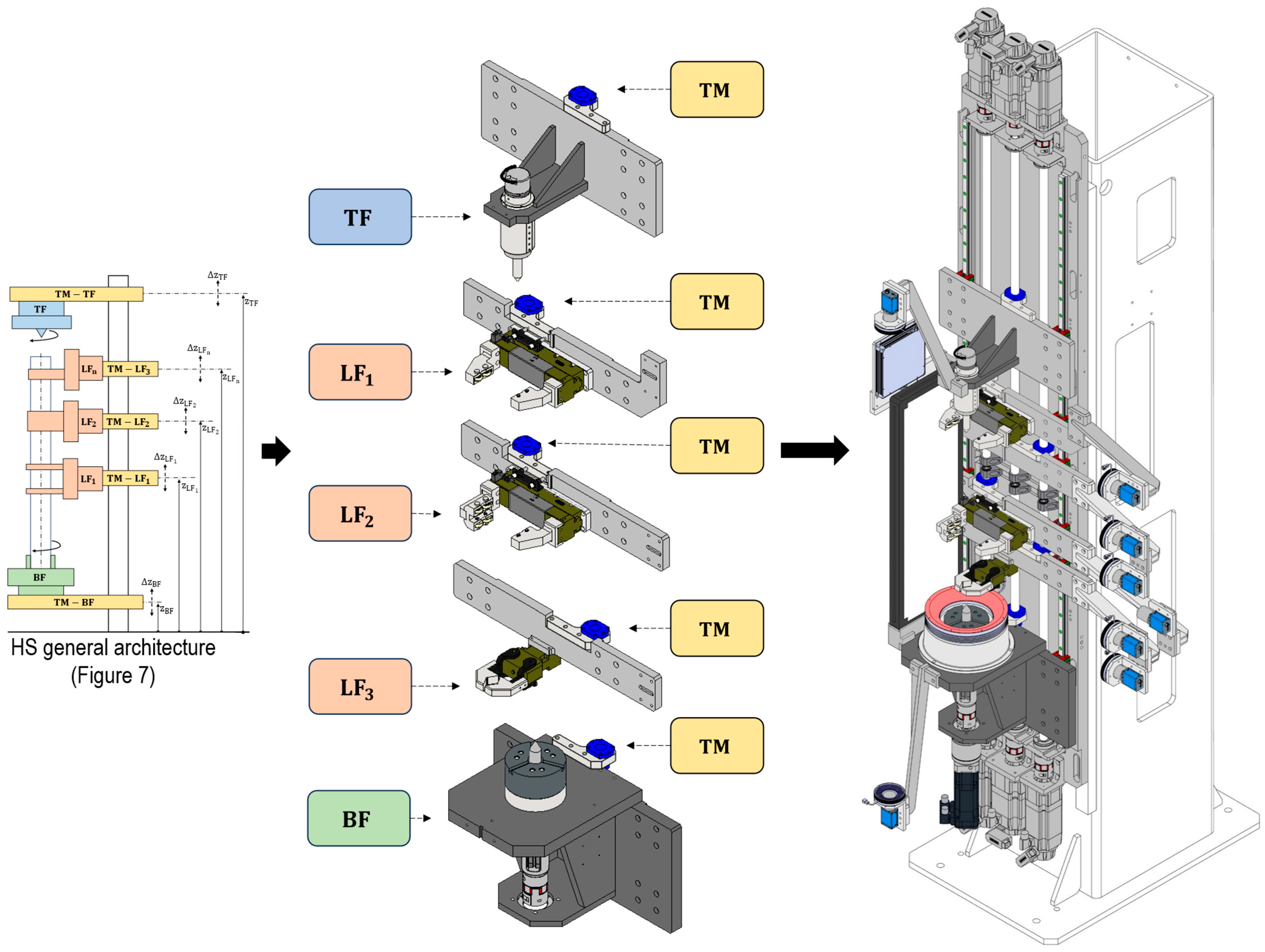
Figure 7, which can be instantiated and customised according to the specific characteristics of the product family. The following sections describe each inspection task in more detail.
4.2. Inspection Task 1
In
inspection station 1 (right portion of
Figure 7), the reconfigurable HS hardware consists of three primary categories of fixtures: a Bottom Fixture (BF), a Top Fixture (TF), and multiple Lateral Fixtures (LFs). The LFs are distributed along the product’s axis of symmetry and play a critical role in supporting and constraining multi-body assemblies with residual DoF.
Each fixture is mounted on a Translational Module (TM), which enables reconfiguration by allowing positional adjustments. All TMs, identified by their nominal z-position (measured from a platform reference point), are installed on a translational platform. Depending on design requirements, each module can provide linear and/or rotational DoF. The maximum translational excursion (
) or rotational range (
) defines the operational capability of each module. In
Figure 7, double arrow lines (e.g.,
) illustrate an example of linear translational excursion for each fixture class.
The use of TMs allows the HS to be reconfigured to accommodate various products. In certain configurations, one or more fixtures (e.g., BF, TF, or LFs) may also serve as actuation systems, enabling repositioning (i.e., rotation or translation) of the product during inspection. This design approach allows a single hardware platform to support multiple product variants.
The design process for inspection station 1 includes the following: (i) selecting the specific physical implementation of each fixture (TF, BF, and LFs); (ii) determining the number of required LFs; (iii) defining the characteristics of each TM, including its nominal position, DoF, and excursion ranges; and (iv) identifying the fixture(s) responsible for actuating the product during inspection.
4.3. Inspection Task 2
Inspection station 2 (left portion of
Figure 7) employs an anthropomorphic 6-DoF robotic arm equipped with a Reconfigurable Gripper (RG) capable of manipulating all products within the target family. During inspection, the robot’s joints are locked, effectively transforming the robot and gripper into a static fixturing system that holds the product in the required orientation. Additionally, the same robotic arm can be used for product loading and unloading, in alignment with current trends in advanced manufacturing automation.
Designing inspection station 2 involves the following: (i) selecting a robotic arm with sufficient workspace and payload capacity and (ii) developing an RG capable of securely handling all parts within the designated product family.
Since the RG can be considered a specialised version of the LFs used in
inspection station 1, the case study presented in
Section 5 focuses primarily on fixtures. However, the underlying principles and results are equally applicable to gripper design in
inspection station 2.
5. Experimental Results
This case study represents the third level of contribution outlined in this paper (
Figure 1), illustrating the industrial application of the reconfigurable HS design support framework introduced in
Section 3, utilising the axisymmetric HS architecture presented in
Section 4, and providing a practical implementation within the RIM domain. The specific application involves an automated cell developed for the visual inspection of half-shafts manufactured by GKN Driveline.
GKN Driveline needed to inspect over 200 variants of half-shafts produced across multiple manufacturing facilities in Florence (Italy), Birmingham (United Kingdom), and Mosel (Germany). These parts differ significantly in length, diameter, and structural complexity. Inspection tasks include presence or absence verification, assembly checks, dimensional accuracy, and surface defect detection, covering over 60 possible defect types distributed across the entire surface of the shaft, including the 360° lateral surface, as well as the top and bottom regions.
Initially, the inspection process was conducted manually, requiring up to one minute per part. Given that each operator was responsible for inspecting over 500 parts per shift, manual inspection was highly susceptible to fatigue and inconsistency, compromising both process reliability and scalability. While this motivated the transition toward an automated solution, the high frequency of product changes presented substantial challenges to automation. Rigid, dedicated inspection cells were deemed unfeasible due to lengthy reconfiguration times and high implementation costs. Each new product variant required extensive mechanical redesign and low-level software programming, significantly limiting the reusability of existing setups and delaying deployment.
These constraints underscored the need for a flexible and rapidly reconfigurable inspection solution, capable of automatically adapting to a wide range of half-shaft variants while minimising setup time and maximising inspection efficiency.
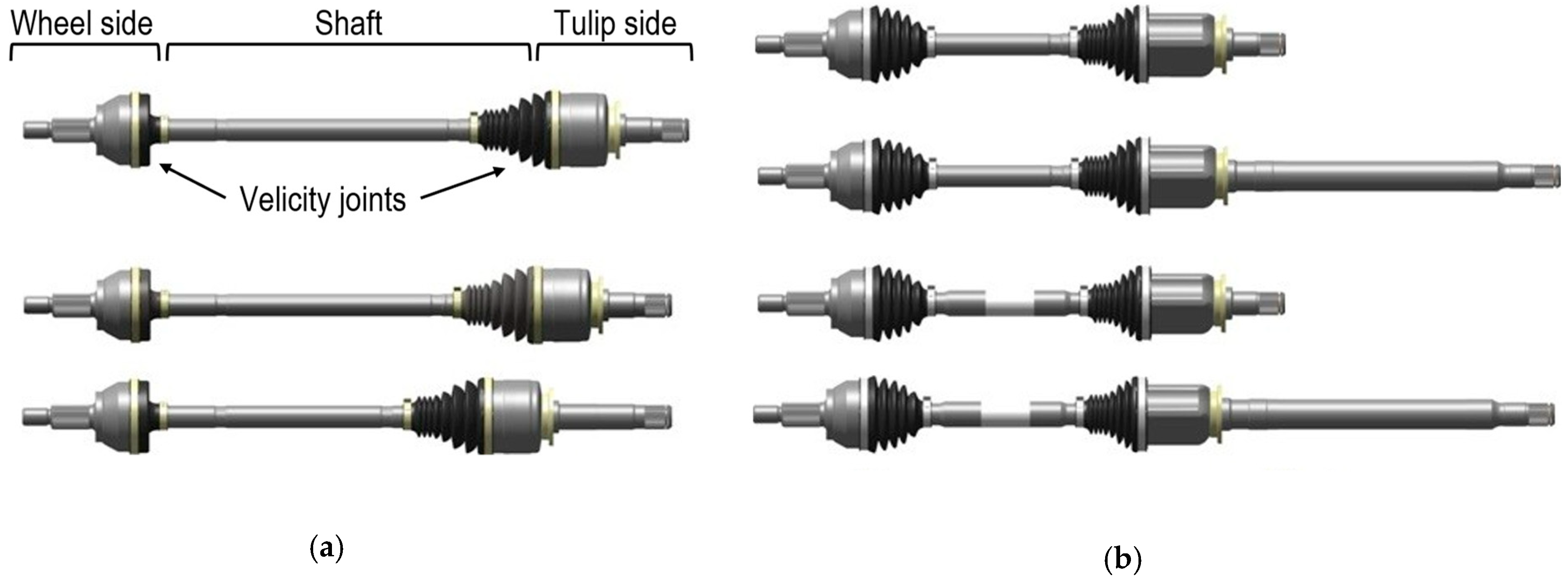
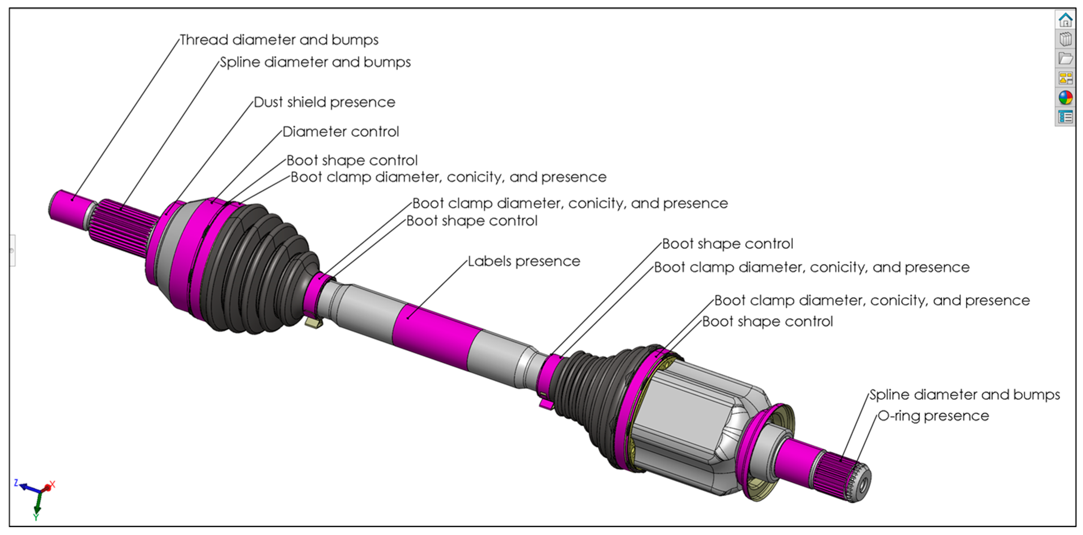
A half-shaft (or driveshaft, depicted in
Figure 8) functions as the dynamic link between a vehicle’s engine and its drive wheels. It transmits both torque and steering inputs, compensates for suspension motion, and mitigates vibrations. Each driveshaft is an axisymmetric component composed of two constant velocity joints, one fixed at the wheel end and the other sliding at the gearbox output, connected by a central shaft.
While a previous study [
6] analysed the system from an FVIS perspective, the present work focuses specifically on the design of the HS.
Section 5.1,
Section 5.2,
Section 5.3 and
Section 5.4 focus on
inspection station 1, as defined in the HS architecture (
Figure 7), which performs a 360° lateral inspection.
Inspection station 2, on the other hand, is equipped with a 6-DoF robotic arm and an RG, capable of accommodating the full range of product variants.
5.1. Step a
The comprehensive product catalogue was mapped to include all half-shaft variants manufactured globally. Design data were extracted from technical drawings and CAD models, while inspection requirements were collected separately. GKN Driveline employs an internal classification system that defines four half-shaft families based on joint type; however, this taxonomy proved insufficient for inspection design.
As illustrated in
Figure 8, even products within the same family can differ significantly in dimensions and surface features (e.g., threads, grooves). The overall length of half-shafts ranges from 625.45 mm to 1164.40 mm. Additional details regarding half-shaft dimensions and construction features are available in [
6].
To enable machine-readable data throughout the design process, relevant information was embedded into the CAD model using PMI semantic annotations via the SolidWorks MBD module (SolidWorks 2023 SP2.1) [
63], in alignment with the MBD paradigm. While this module allows the addition of PMI, it does not support hierarchical organisation of information. To overcome this limitation and meet the requirements of the study, a novel integration of SolidWorks
configurations [
64] and
display states [
65], alongside
PMI annotations, was employed to structure the MBD dataset effectively.
Configurations in SolidWorks allow the creation of multiple variations of a part or assembly within a single document. Each configuration can represent a different set of dimensions, features, components, or properties, making them useful for managing product families or alternate design states. Display states, on the other hand, control the visual appearance of components, such as feature colour or visibility.
In the context of this MBD methodology, configurations and display states were repurposed as follows:
The configuration name defines a specific category of semantic information (e.g., fixturing features, inspection features).
The display state is associated with each configuration and highlights relevant geometry through colour coding (e.g., red for clamps, purple for inspection areas).
The textual PMI annotations are embedded in the model and linked to the geometry; these provide semantic details such as the usage constraints (e.g., painted surface), associated equipment (e.g., clamp, gripper), and types of quality control tasks (e.g., presence check).
Each configuration displays only its corresponding display state and PMI annotations, effectively representing a discrete layer of information. This structured approach enables the model to capture specific stages of the design process within a unified and accessible digital environment, consistent with the MBD methodology. Examples include O1/O2 (fixturing and motion system selection) and O3/O4 (inspection task definition).
After retrieving and embedding the product information, the candidate features for fixturing and motion systems were identified directly within the CAD model. Based on these features, a corresponding set of suitable equipment was selected:
Fixtures: an idle tailstock, a parallel gripper, a steady rest, and rolling bearing V-blocks.
Motion systems: a motorised self-centring chuck and a motorised headstock.
For each equipment type, a set of requirements (e.g., minimum feature length, allowable surface types) was defined and documented in a spreadsheet. These requirements were then used in conjunction with the enriched CAD model to perform a rule-based matching process, following the methodology outlined in
Section 3.1.1 (
Step a.1). Each candidate feature was systematically evaluated and linked to all compatible fixturing and motion systems stored in the database through a semi-automated filtering procedure, as illustrated in
Figure 4. This activity, repeated for each product variant, completed
Step a.1, resulting in the O1 class (
compatible fixturing system sets) and the O2 class (
compatible motion system sets).
Both outputs were embedded in the CAD model using
PMI annotations and
display states, stored in separate product
configuration layers within the MBD dataset. Surface highlighting enables quick identification of valid fixturing areas, while annotations specify the compatible equipment (e.g., clamp, robotic gripper, locator).
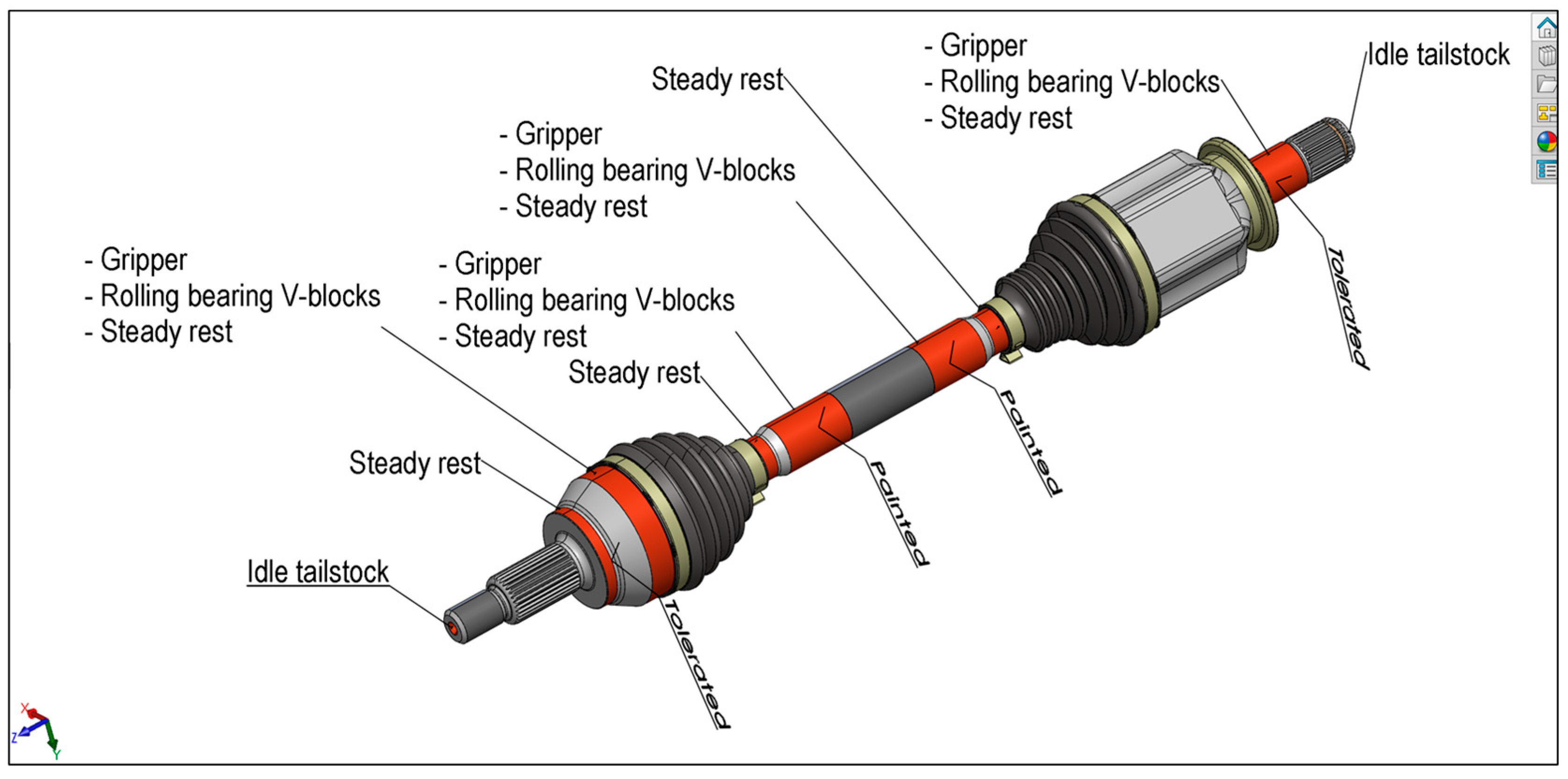
Figure 9 shows a 3D model of a half-shaft with red-highlighted surfaces representing potential fixturing features, along with textual annotations indicating applicable systems and relevant manufacturing notes (e.g., painted surface).
In parallel, during
Step a.2, all inspection task details were defined and embedded into the CAD model, resulting in the O3 (
inspection task sets) and O4 (
inspection view sets) classes.
Figure 10 illustrates a CAD model configuration focused on inspection-related information (O3), where purple-highlighted features are annotated with the corresponding inspection types and control requirements.
5.2. Step b
After identifying the candidate features and compatible fixturing/motion systems (
Step a), feasible combinations of fixturing and motion elements were derived for each product variant and encoded as the O5 class. The general reconfigurable HS architecture (
Figure 7) helped reduce design complexity by narrowing the space of potential solutions. Additionally, custom design constraints were introduced; for instance, surfaces marked as “controllable features” or “painted” were explicitly excluded from fixturing to prevent mechanical damage or occlusion during inspection. A vertical layout was selected for
inspection station 1 to optimise space utilisation.
By referencing O1–O4 in the enriched CAD model and applying the established FD rules (
Section 3.3), along with static and stability criteria, designers compiled the corresponding O5 configuration for each half-shaft. O5 information was stored in the CAD model in the same manner as O1 and O2, as it belongs to the same class of structured information and is fully compatible with integration into the MBD dataset.
Step b resulted in the following candidate fixture components: a motorised self-centring chuck or a motorised headstock (both considered a potential BF), an idle tailstock (standard or specialised, as a potential TF), and parallel or double-parallel grippers used as LS, each providing different levels of constraint. Possible actuation systems were limited to motorised units for the TF or BF (i.e., the self-centring chuck or the headstock).
The selected fixture components and motion systems were then combined for each O5 configuration on a product-specific basis, ensuring both static stability and complete inspection coverage.
5.3. Step c
In Step c, the O5 outputs derived for each product variant in Step b were aggregated to form O6, which defines the final reconfigurable HS architecture capable of accommodating the full range of product family variations.
Figure 11 illustrates an example workflow for selecting a TF across three distinct product variants. By comparing the z-position and type (e.g., centring holes) of the fixturing features, it becomes evident that the same fixture type (i.e., a tailstock) can be reused at different positions (z
1, z
2, z
3), depending on the specific product.
According to the similarity classification in
Figure 5, this represents a “completely shared feature/different positions” scenario. Two possible solutions are available: (a) duplicating a fixture or (b) translating a single fixture across the required z-range. In this case, duplication is not viable, as the fixture positioned for Product 1 would result in collisions with Products 2 and 3. Therefore, a translational tailstock with sufficient stroke (∆z, as shown in
Figure 11) was selected to accommodate all variants without interference.
A similar decision-making process, based on similarity analysis and feature alignment, was applied to select the physical implementations for all fixture components comprising the HS.
Table 2 summarises the key components of the system, indicating for each element (first column) (i) the similarity level according to the classification scheme in
Figure 5; (ii) the physical fixture realisation; (iii) the flexibility capability (i.e., the ability to accommodate product variants without hardware changes); and (iv) the reconfigurability capability (i.e., the ability to adapt via hardware modifications or repositioning).
Additionally, during this stage, the motion systems were evaluated based on their axial stroke and kinematic compatibility with the selected fixtures. As a result, the conceptual configuration of a fully reconfigurable HS, capable of handling the complete product portfolio, was defined.
5.4. Step d
Based on the O6 output defined in
Step c, the final reconfigurable HS architecture was implemented.
Figure 12 shows the completed
inspection station 1.
In accordance with the general architecture outlined in
Figure 7, the system comprised various fixture modules (BF, TF, and LFs) mounted on translating platforms (TM modules), actuated by recirculating ball screws and motorised lead screws. These translation mechanisms were also used to control the movement of NC cameras and lighting systems, enabling dynamic adaptation to different product geometries. To support autonomous operation, all NC translation modules were computer-controlled.
In this HS configuration, central support (LFs) was provided by diametrically adaptable grippers (i.e., commercially available parallel-closing grippers equipped with custom neoprene contact surfaces). These components ensured adaptability to varying shaft diameters while preventing surface damage and maintaining coaxial alignment between the headstock and tailstock. An additional LF (
in
Figure 12) was included to support loading and unloading operations. This fixture, a stabilising parallel gripper mounted on its own translation module, was designed to avoid any mechanical constraint or interference with the part during inspection.
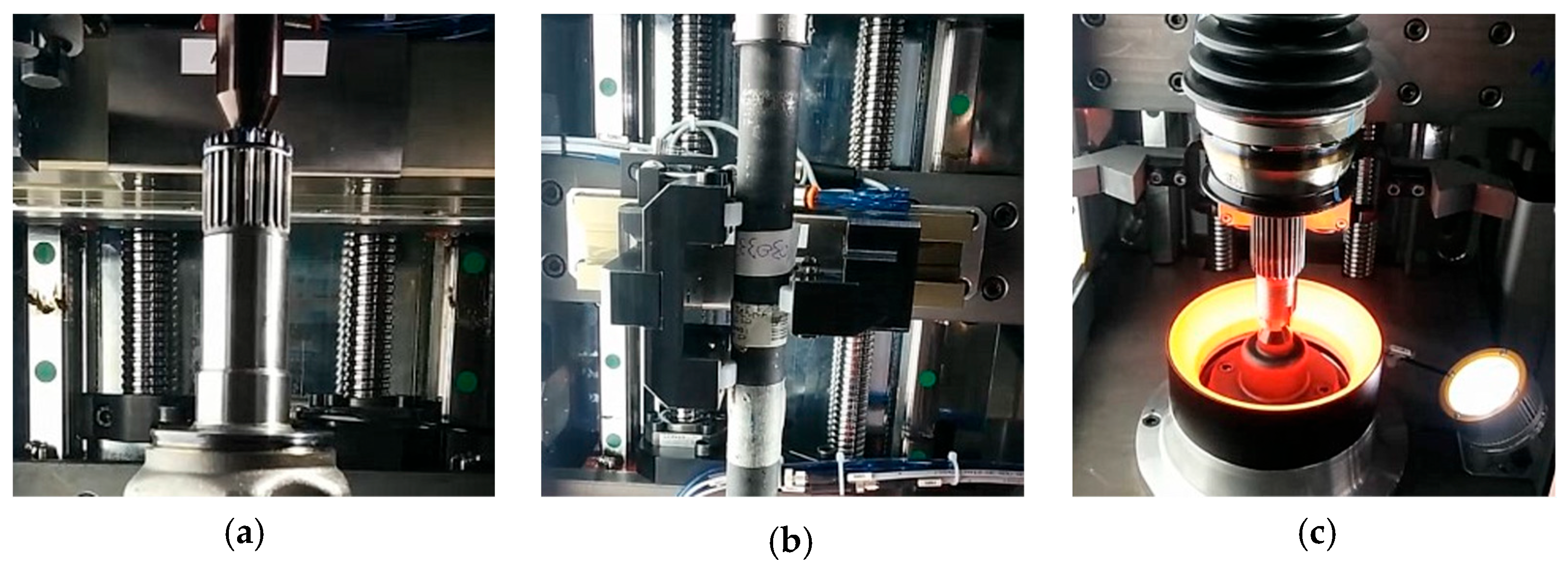
The HS architecture was initially validated in a laboratory environment using manual reconfiguration (
Figure 13). Actuated TM modules and their integration into a unified platform were developed and tested in a subsequent phase (
Figure 14), prior to deployment in the company’s production facilities. Its modular structure enables reuse of the base platform across different subsystems (e.g., fixtures, cameras, lighting), enhancing scalability and maintainability. The final HS includes five TMs, each driven by a 5 mm-pitch recirculating ball screw. To minimise cost and component variability, only two screw lengths were adopted: 945 mm for the lower modules (translating BF,
, and
) and 1290 mm for the upper ones (translating TF and
).
The system enables rapid vertical adjustment through NC axis control, without requiring manual intervention or hardware modifications. This design ensures compatibility with the entire global half-shaft portfolio and with future product variants, which can be accommodated by simply updating the modules mounted on the TM platforms.
5.5. Performance Assessment of the Automated VIS
The implemented inspection station achieves 100% inspection coverage of all assembled half-shafts across a portfolio of 220 different products, with an inspection cycle time under 30 s for detecting over 60 distinct defect types, including presence/absence, dimensional tolerance deviations, misalignments, surface damage, and positioning errors. The system’s main technical aspects and performances are detailed in [
6] and summarised below.
The system integrates a machine vision setup composed of five NC cameras and a dedicated lighting configuration. Software and hardware reconfiguration are governed by a “Reconfiguration file”, which defines the parameters for camera and lighting settings, inspection algorithms, and the coordinated movements of robot and NC components. A graphical user interface supports intuitive setup of new inspection routines.
The inspection process, orchestrated by a Programmable Logic Controller (PLC)/Personal Computer (PC)-based architecture, begins by retrieving the appropriate “Reconfiguration file” according to the part’s specifications. A 6-DoF robot loads each half-shaft into the first station for top and bottom image capture and then transfers it to a second station where the part is fixtured and fully inspected. Each camera captures 36 images per full rotation, which are processed by dedicated software. The results are sent to the PLC, which determines whether the part is approved for palletisation or flagged for reinspection. The graphical user interface displays real-time visual feedback, using green indicators for defect-free parts and red for detected defects.
Initial testing with a batch of 60 parts yielded the following results: 15 true positives (defective parts correctly identified as defective), 4 false positives (non-defective parts incorrectly flagged as defective), 41 true negatives (non-defective parts correctly identified as defect-free), and 0 false negatives (defective parts that were mistakenly classified as non-defective). These results correspond to a True Positive Rate (TPR) of 100%, and a False Positive Rate (FPR) of 9%, meaning that approximately 1 in 11 good parts was erroneously flagged as defective (conservative perspective). Following fine-tuning using a large-scale production dataset and optimisation of inspection thresholds, the system, deployed across seven pilot cells, consistently achieved 100% TPR and 2% FPR, including on newly introduced product variants.
This solution significantly improves productivity by enabling fast and fully automated 100% quality control, while eliminating repetitive and error-prone manual inspection tasks. The total cycle time, which includes both the active inspection phase and the automated, software-guided reconfiguration, is under 30 s per part. This improvement has resulted in a 40% increase in throughput, enabling the inspection of over 1000 half-shafts per shift.
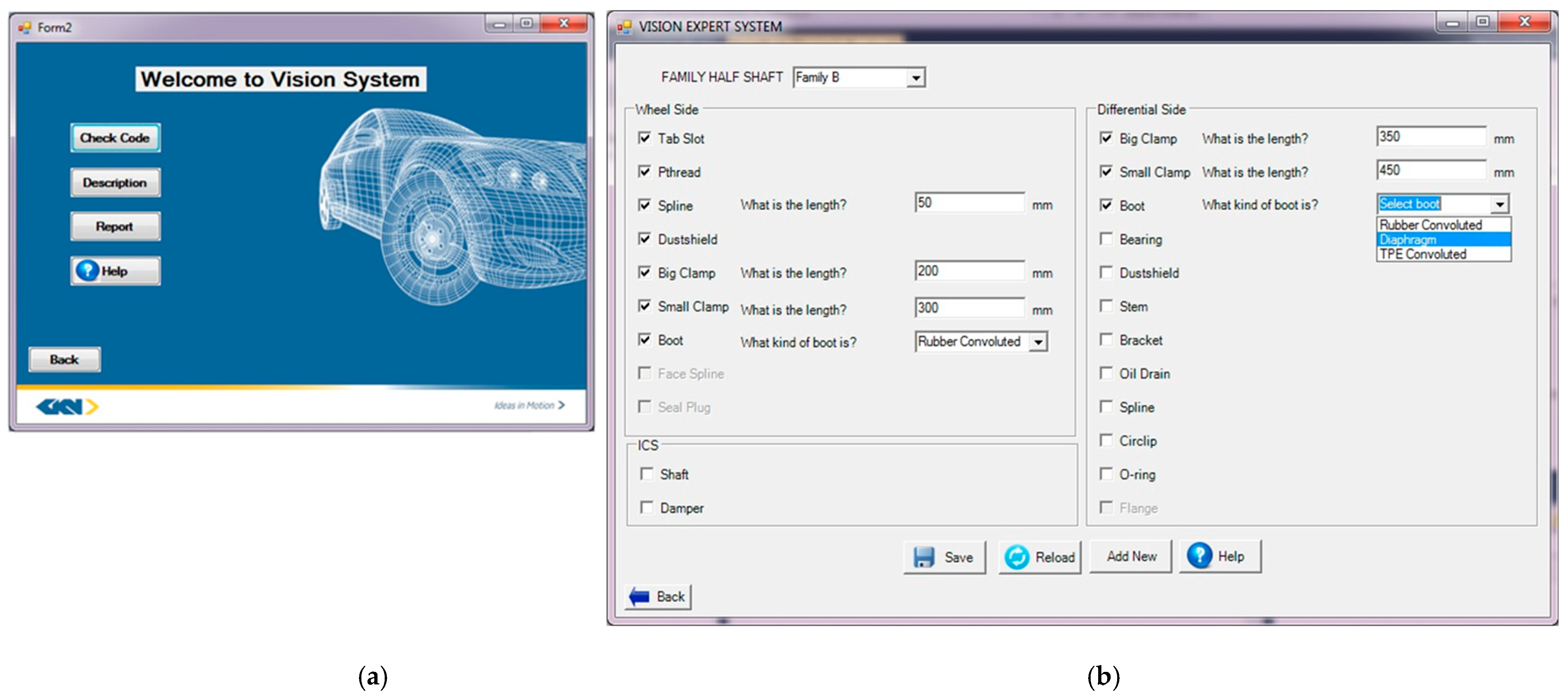
Importantly, low-level coding for reprogramming is no longer required. The system features an intuitive user interface, with the main dashboard shown in
Figure 15a. Users can register a new product by entering its unique ID, search for similar existing products, or, if necessary, configure an entirely new inspection task from scratch. The routine configuration interface (
Figure 15b) guides users through the process via a combination of dropdown menus (e.g., to select the product family), checkboxes (e.g., to specify defect types), and editable fields (e.g., for specifying component dimensions). Once a new configuration is defined and saved, it is automatically added to the system’s knowledge base for future reuse.
The estimated offline software configuration and task setup time is on the order of a few minutes, requires no programming expertise, and has no impact on the active inspection cycle time.
6. Discussion
The RQs introduced in
Section 2.5 are addressed throughout
Section 3,
Section 4 and
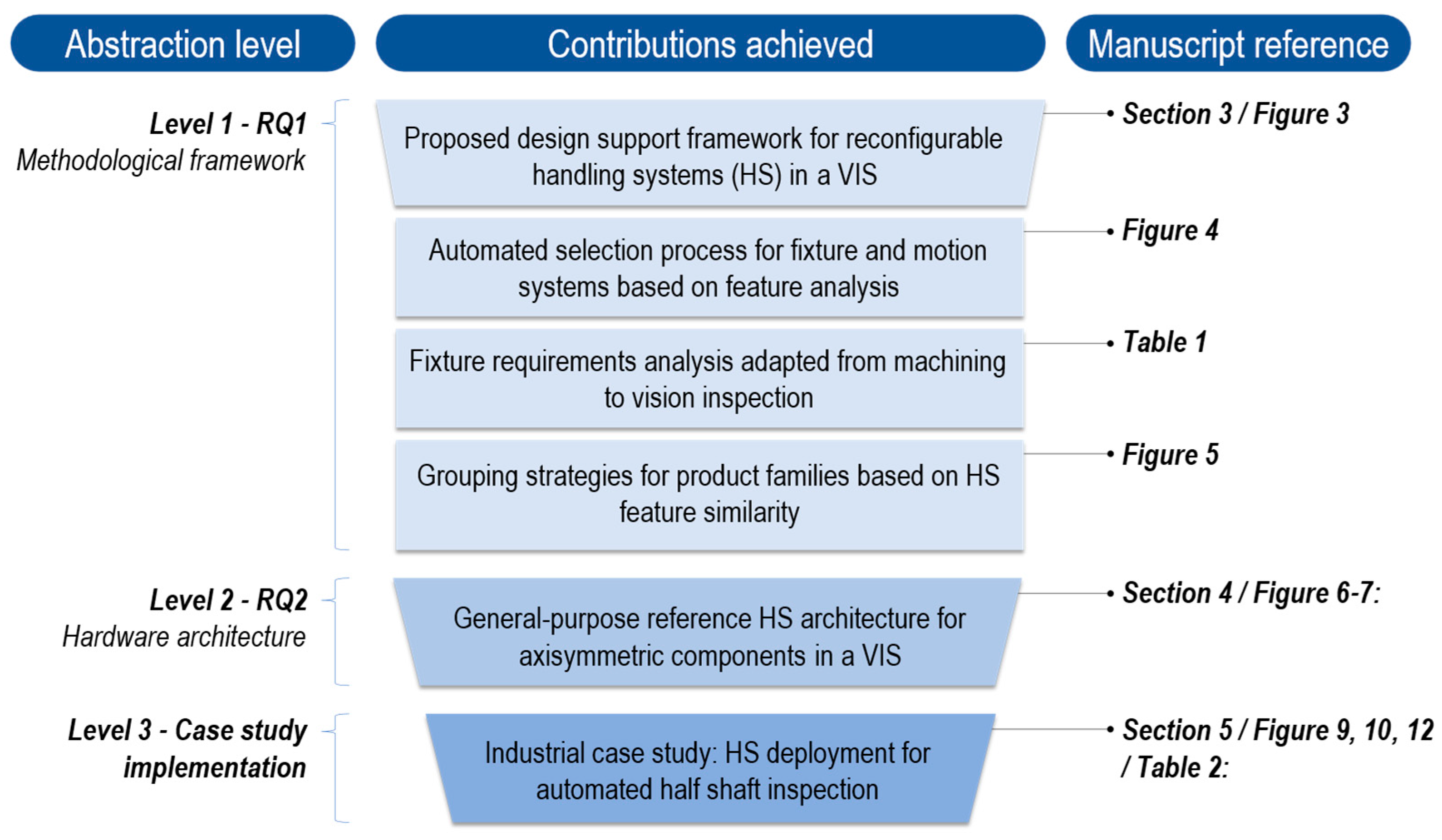
Section 5 culminating in a detailed summary of the achieved contributions presented in
Figure 16. This figure reflects the funnel structure outlined in
Figure 1, aligning each claimed contribution with its corresponding abstraction level and explicitly mapping them to the relevant sections, tables, or figures.
6.1. Level 1 Contribution: The Proposed Design Support Framework
The structured design support framework, conceived to be agnostic to both product type and manufacturing sector, was complemented by specific design tools, such as the fixture requirements defined in
Table 1 and the grouping strategies shown in
Figure 4.
From an information flow perspective, the introduction of an enriched CAD model to organise both geometric and semantic data, particularly in Step a, represents a significant advancement toward alignment with MBD principles. Nonetheless, several technical barriers currently hinder the full implementation and scalability of this approach.
Firstly, the automated encoding and decoding of semantic data during the design stage remain underdeveloped, which impedes the efficient reuse of PMI across downstream Computer-Aided Technologies (CAx) systems. Secondly, the current implementation in SolidWorks, based on PMI annotations, model configurations, and display states, relies on proprietary software tools and non-standardised procedures. This introduces interoperability challenges and restricts the reuse of data in cross-platform environments. Moreover, scalability becomes a concern as the volume of embedded information increases, making it progressively more difficult to manage and maintain semantic consistency throughout the product lifecycle.
To address these issues, future work should focus on formalising the structure of semantic datasets. The adoption of neutral and standardised file formats, such as STEP AP242, holds significant promise for improving automation, interoperability, and long-term data usability across tools and domains [
21,
28,
59,
60,
61].
Additionally, tasks in
Step b and
Step c, such as component selection or HS configuration, still rely on traditional CAFD approaches and expert input. While this work lays a foundation for structuring preliminary design data, full automation of data processing (such as the scenarios illustrated in
Figure 4) has not yet been realised. Greater integration of MBD strategies could enable the direct reuse and postprocessing of structured, machine-readable data in downstream CAx applications. For example, outputs like O1 and O2 could be automatically generated by matching CAD-extracted product constraints with fixture and motion system requirements stored in digital libraries.
6.2. Level 2 Contribution: The Reference Hardware Architecture
The proposed reconfigurable HS architecture demonstrated promising results, successfully adapting to more than 200 different axisymmetric components across four distinct product families.
Future research should explore the generalisation of this architecture to a broader range of product categories, including non-axisymmetric families. This may be achieved by replacing the axis of symmetry with a reference axis tailored to the specific geometry of each product.
6.3. Level 3 Contribution: Case Study Implementation
The industrial case study illustrates the application of a reconfigurable, vision-based RIM aligned with the proposed framework (
Section 3) and based on the hardware architecture developed for axisymmetric parts (
Section 4). This system was employed to inspect a family of half-shafts used in the automotive sector, as part of a real-world use case developed in collaboration with GKN, a global automotive supplier. The solution has been successfully implemented across multiple production plants.
However, since both the design framework and reference hardware architecture are intended to be agnostic to the product and manufacturing sectors, further research is encouraged to validate the approach in other manufacturing domains.
7. Conclusions
This study investigated the design of contactless, flexible, and reconfigurable Vision Inspection Systems (VISs), also referred to as vision-based Reconfigurable Inspection Machines (RIMs), with particular emphasis on the handling system (HS), a critical yet often underexplored subsystem compared to vision hardware and data processing components. To address this gap, the paper introduced a multi-level contribution encompassing both methodological and architectural innovations.
A structured design support framework was proposed, articulated in four sequential phases. At the core of this framework is a semantically enriched CAD model, which serves as the primary source of geometric and functional information throughout the design process, in alignment with Model-Based Definition (MBD) principles. Although the current workflow remains predominantly manual, this foundation lays the groundwork to integrate automated Computer-Aided Fixture Design (CAFD) methodologies.
Complementing the framework, a general-purpose hardware architecture was developed for the inspection of axisymmetric components. This architecture was informed by a review of the relevant literature, patented solutions, and engineering principles drawn from both vision-based RIMs and CAFD systems within the Reconfigurable Manufacturing Systems (RMSs) domain. The proposed configuration, integrating NC modules and robotic manipulators, ensures full inspection coverage and enables rapid reconfiguration.
To assess the practical applicability of the proposed approach, a case study was conducted involving the design and implementation of an automated inspection cell for half-shafts. Deployed across seven pilot cells at a global automotive manufacturer, the system successfully inspected over 200 different half-shaft variants in under 30 s per cycle and detected more than 60 defect types through automatic reconfiguration.
Future research should build upon the three main contributions of this work. From a methodological perspective, efforts should focus on automating the HS design process, minimising reliance on expert input, and integrating CAFD techniques. This includes formalising fixture requirements and linking them to MBD-enriched CAD data to enable intelligent decision-making, potentially through AI-driven approaches. The convergence of MBD-based frameworks and AI-enabled CAFD tools could pave the way for scalable, autonomous solutions for vision-based RIMs across diverse industrial applications. From an architectural perspective, broader testing across a wider range of products, industrial domains, and inspection tasks is encouraged to identify potential limitations and validate the adaptability of the proposed solution.
