Article

Process Development to Repair Aluminum Components, Using EHLA and Laser-Powder DED Techniques

1
Department of Manufacturing Engineering, Faculty of Industrial Engineering, Robotics and Production Management, Technical University of Cluj-Napoca, Memorandumului 28, 400114 Cluj-Napoca, Romania
2
Capgemini Engineering the Netherlands, Reykjavikplein 1, 3543 AK Utrecht, The Netherlands
3
Fraunhofer Institute for Laser Technology, Steinbachstraße 15, 52074 Aachen, Germany
*
Author to whom correspondence should be addressed.
J. Manuf. Mater. Process. 2025, 9(8), 255; https://doi.org/10.3390/jmmp9080255
Submission received: 18 June 2025 / Revised: 26 July 2025 / Accepted: 29 July 2025 / Published: 31 July 2025

Abstract

The article presents a new AM (Additive Manufacturing) process development, necessary to repair parts made from Aluminum 6061 material, with T6 treatment. The laser Directed Energy Deposition (DED) and Extreme High-Speed Directed Energy Deposition (EHLA) capabilities are evaluated for repairing Al large components. To optimize the process parameters, single-track depositions were analyzed for both laser-powder DED (feed rate of 2 m/min) and EHLA (feed rate 20 m/min) for AlSi10Mg and Al6061 powders. The cross-sections of single tracks revealed the bonding characteristics and provided laser-powder DED, a suitable parameter selection for the repair. Three damage types were identified on the Al component to define the specification of the repair process and to highlight the capabilities of laser-powder DED and EHLA in repairing intricate surface scratches and dents. Our research is based on variation of the powder mass flow and beam power, studying the influence of these parameters on the weld bead geometry and bonding quality. The evaluation criteria include bonding defects, crack formation, porosity, and dilution zone depth. The bidirectional path planning strategy was applied with a fly-in and fly-out path for the hatching adjustment and acceleration distance. Samples were etched for a qualitative microstructure analysis, and the HV hardness was tested. The novelty of the paper is the new process parameters for laser-powder DED and EHLA deposition strategies to repair large Al components (6061 T6), using AlSi10Mg and Al6061 powder. Our experimental research tested the defect-free deposition and the compatibility of AlSi10Mg on the Al6061 substrate. The readers could replicate the method presented in this article to repair by laser-powder DED/EHLA large Al parts and avoid the replacement of Al components with new ones.

1. Introduction

1.1. Comparative Analysis of AM Technologies for Repair Application

The shift towards the circular economy in manufacturing operations is a pressing challenge as conventional manufacturing technologies are resource-intensive and optimized for mass production, predominantly in a linear model, where components are manufactured, used, discarded, landfilled, or recycled. A shortage in raw material availability makes replacing a damaged component with a new one not only time- and cost-intensive, but also unsustainable, considering the emissions resulting from the new component manufacturing and transportation and the old component scrapping.
Additive Manufacturing (AM), which deposits material layer by layer in either powder or wire form, presents a promising pathway toward circularity. Specifically, AM enables automated, localized repair of worn high-value components. Among AM techniques, Laser Powder Bed Fusion (LPBF) and Directed Energy Deposition (DED) have emerged as viable options for remanufacturing complex geometries.
LPBF provides high resolution (layer thicknesses of 30–50 µm) [1] and has been successfully applied in repair scenarios—for example, in burner components, as demonstrated by Andersson et al. [2]. However, LPBF’s use in repair remains constrained by build volume limitations and the need to place and orient parts within the powder bed. As Sato et al. [3] note, process planning, alignment, and toolpath generation for repair tasks are particularly challenging in LPBF systems.
DED processes, in contrast, enable more flexible, scalable repairs. A focused heat source—laser, electron beam, or arc—is used to melt feedstock material (powder or wire), which is delivered through nozzles and deposited directly onto the damaged area [4]. This approach eliminates the need for support structures and allows for integration with robotic or CNC systems, facilitating in situ, localized repair of large and complex components. When laser energy is combined with powder feedstock (referred to as LP-DED), the technology has found success in sectors such as aerospace and tooling, offering layer thicknesses of 200–1000 µm and travel speeds of 0.2–2 m/min [5].
A recent innovation, the extreme high-speed version of LP-DED, called EHLA (from the German Extremes Hochgeschwindigkeits-Laserauftragschweißen), patented by the Fraunhofer ILT, (DE 10 2011 100 456 A1), further expands the potential of laser-based repair. EHLA operates at feed rates exceeding 20 m/min, achieving significantly thinner layers and reduced surface roughness compared to LP-DED—attributes that are particularly beneficial in precision repair applications [6,7,8]. Originally developed for coating rotationally symmetric parts (e.g., brake discs, hydraulic cylinders), EHLA has since been adapted for thin walls and cuboid geometries, making it increasingly relevant for repair applications [9].
Nozzle geometry plays a critical role in deposition efficiency and powder utilization. Coaxial nozzles, particularly those with three, four, or even six discrete feed channels, offer better control and uniformity, making them more suitable for precision repair tasks than off-axis or wire-fed designs [10,11].
To understand the difference between the LP-DED and EHLA process, it is essential to look at the differences in the positioning of the nozzle or powder gas jet in relation to the processing surface. The key difference between LP-DED and EHLA lies in the positioning of the nozzle tip relative to the processing surface. In LP-DED, the focus position of the powder gas jet is on the processing surface, while in EHLA, it is positioned above the surface, as shown on Figure 1. This positioning difference results in EHLA melting the metal powder before it hits the target surface, creating a smaller melt pool and inducing less heat in the substrate.
This positioning is responsible for the fact that conventional LP-DED creates the melt pool on the target surface, introducing significant heat in the substrate. The outward positioning, however, makes it possible to melt the metal powder before hitting the target surface; therefore, it creates a smaller melt pool, inducing less heat in the substrate. This process also reduces the melting time and allows for a fast feed rate, from a few m/min (as in conventional LP-DED), to hundreds of m/min, from which the “extreme high-speed” characteristic of the EHLA technology results [4,11]. The resulting differences in technology performance are presented in Table 1.

1.2. Challenges of Aluminum Laser Deposition

Aluminum, a crucial material in mobility, mechanical, tooling, and building industries, saw a 4% annual increase in demand and a 60% price increase per ton in 2022 [9]. Consequently, there is a growing interest in developing efficient repair methods to extend component lifetimes and avoid new component manufacturing.
However, processing aluminum by laser deposition techniques remains challenging due to several factors:
  • High reflectivity, which reduces laser energy absorption and makes consistent melting and adhesion difficult;
  • High thermal conductivity, leading to rapid heat dissipation and insufficient melting;
  • Susceptibility to oxidation, resulting in porous structures;
  • Low viscosity when molten, potentially causing uneven deposition;
  • High hydrogen solubility in its molten state, increasing the formation of porous structures [17].
LP-DED has proven effective for high-volume deposition of materials such as titanium, steel, and nickel-based alloys in aerospace applications [12,13,14,15,16]. However, its application to aluminum alloys remains limited due to the material’s high reflectivity and thermal conductivity, which hinder melt pool stability and powder adhesion [22,23]. Studies by Lv et al. [22] and Hermann et al. [23] show that high laser powers (2800–3600 W) are needed to achieve crack- and pore-free AlSi10Mg depositions, even with thin (~0.5 mm) layers. Post-deposition heat treatments improve tensile strength and stabilize microhardness profiles.
More recent studies have demonstrated that EHLA may offer a better pathway for aluminum repair. Because most of the laser energy is absorbed by the powder above the substrate (~80%), thermal load on the component is drastically reduced [18]. Li et al. [24] report successful deposition of corrosion- and wear-resistant multi-material layers on 5083 Al substrates at 30 m/min, achieving a fivefold increase in surface hardness.
T. Li et al. [19] compared EHLA and LP-DED deposition of AISI 4140, noting that while EHLA required 95 layers versus 22 for a 10 mm build height, it reduced the HAZ from 500 µm to 100 µm. Although much of the literature on aluminum DED focuses on coatings, Dong et al. [25] reported successful LP-DED repair of aeroengine casing components in AlSi10Mg, achieving near-substrate tensile strength and hardness values (215 ± 12 MPa vs. 225 MPa; 78–85 HV0.2). Koss et al. [9] demonstrated EHLA deposition at 100–200 m/min using 8000 W lasers and powder feed rates of 22–34 g/min—achieving 100 µm layer thicknesses at productivity rates up to 1300 cm2/min.
Despite growing evidence of EHLA’s benefits for aluminum coating, few studies have evaluated its potential for structural repair or compared it systematically to LP-DED in this context. Moreover, the influence of process parameters on bonding, porosity, and hardness in aluminum repair—particularly for Al6061 and AlSi10Mg—remains underexplored.
This study aims to fill that gap by experimentally comparing LP-DED and EHLA deposition strategies for aluminum repair applications. Specifically, the deposition characteristics, bonding quality, and hardness of single tracks deposited on Al substrates are analyzed.

2. Materials and Methods

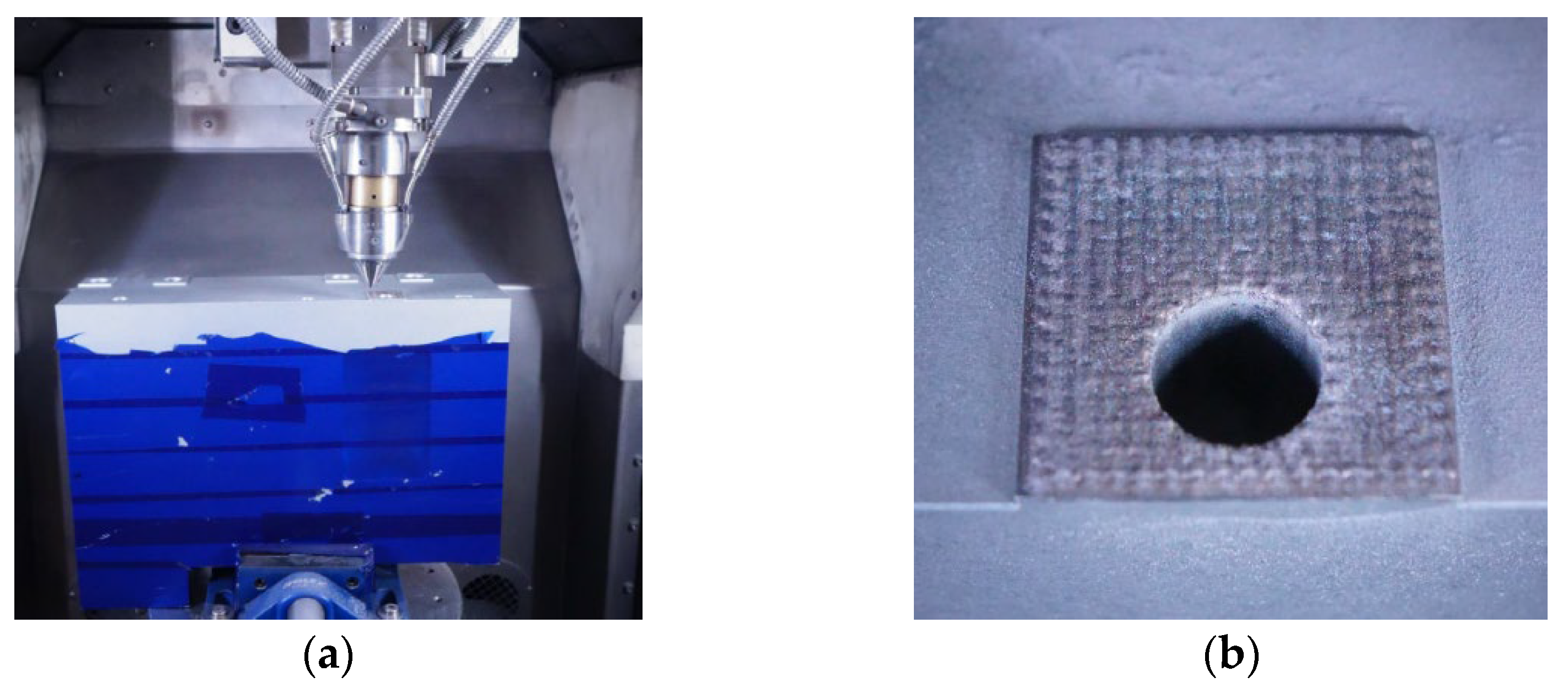
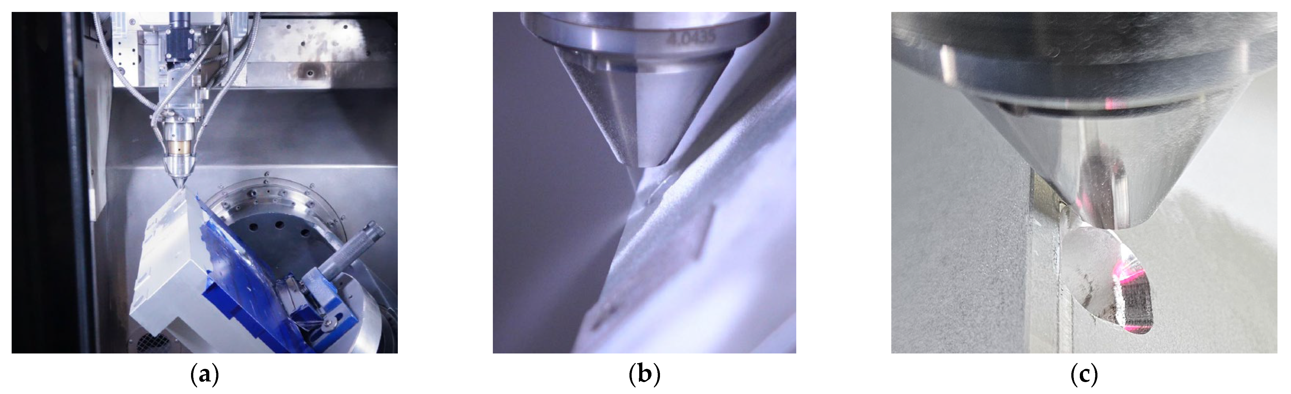
2.1. Experimental Setup

All experiments (LB-DED and EHLA depositions) were conducted on a modified 5-axis CNC machine AML500 developed by Makino Asia Pte. Ltd. (Gul Ave, Singapore), (see Figure 2) The machine has workpiece dimensions of X:500 mm, Y:400 mm, and Z:400 mm, and the maximum feed rate is 30 m/min. The powder nozzle is a continuous coaxial Highno. 4.0 from HD Sonderoptiken (Uebach-Palenberg, Germany) Standoff distance for the LB-DED deposition was 9 mm and for EHLA, 10 mm, with a typical powder focus diameter of 0.7 mm at a powder mass flow of 3 g/min. The powder feeder is a disk-type feeder from Oerlikon Metco (Wohlen, Switzerland). The applied beam source is an LDF5000-30 with OTZ5 processing optics from Laserline GmbH (Muelheim-Kaerlich, Germany). The processing optics are equipped with an optical zoom system which can vary the focus and processing diameter between 1 mm ≤ df ≤ 3 mm.

2.2. Materials

The damaged component is a 6061 Al spacer component with T6 treatment. The spacer’s main functionality is to hold an accurate distance; therefore, the critical surfaces were investigated where the distance accuracy was affected by surface scratches and dents. The T6 treatment consists of a solution heat treatment to homogenize the composition by dissolving the soluble phases containing Mg, quenching, and a natural or artificial aging at room temperature or increased temperatures of 150–210 °C [26].
For the process parameter evaluation, Al6061 material with a T6 heat treatment is used as a substrate. The powder material is also a matching Al6061 alloy from TLS ECKART (chemical composition in Table 2) and is specified with a powder particle distribution of 20–63 µm. Initial attempts to identify suitable EHLA parameters for Al6061 powder were unsuccessful due to excessive cracking and poor layer adhesion. This led us to explore AlSi10Mg from FERHMANN as an alternative feedstock for EHLA deposition, as this allot is commonly used in AM.

2.3. Single-Track Process Parameter Study

In the first phase of the process study, a parameter study was conducted by depositing single tracks with a variation of selected process parameters (see Figure 3a). Weld beads 30 mm in length were deposited and were qualitatively analyzed by metallographic cross-sections. The following criteria were used for the evaluation: bonding defects, crack formation, porosity, and dilution-zone depth.
As observed in the example in Figure 3b in the cross-section with 500 µm magnification, small porosity, possibly from gas entrapment, still occurs. This occurs when the feedstock powder has residual internal pores or moisture and gas pockets are released once the powder melts, but they do not always migrate to the melt pool surface before the melt pool solidifies and entraps them.
The beam diameter is kept constant at dbeam = 1.2 mm and the feed rate at vtool = 20 m/min for EHLA and at vtool = 2 m/min for conventional LP-DED deposition. The shielding and carrier gases are also kept constant at Qshield = 12 L/min and QS = 8 L/min for LP-DED and EHLA. By the variation of the powder mass flow and beam power, the influence of these parameters on the weld bead geometry and bonding quality can be analyzed. The following process parameter combinations are applied for the single-track experiments listed in Table 3.
The process parameter set for LP-DED and EHLA is selected respectively for the transfer to the coating process. Furthermore, the single tracks resulting from the selected process parameter sets are etched for a qualitative microstructure analysis. As an initial evaluation of the mechanical property resulting from a local single-track repair, the etched cross-section is used for HV hardness measurements.

2.4. Single-Layer Process Parameter Study

In the second phase of the parameter development, the selected LP-DED and EHLA parameters are used to deposit a single-layer coating. For the single-layer deposit, the process parameters listed in Table 4 were used.
Within this study, a bidirectional path-planning strategy is applied with a fly-in and fly-out path for the hatching adjustment and acceleration distance (see Figure 4). Hatch levels were chosen based on preliminary experiments and literature values. We selected 40%, 50%, and 60% overlap to investigate the effect on porosity and inter-track bonding. These levels represent a range from minimal overlap to significant overlap, allowing us to identify the optimal balance between deposition rate and deposit quality.
For the evaluation, each coating specimen is metallographically analyzed by an etched cross-section. Like the single tracks, the initial evaluation of the mechanical properties is conducted by HV hardness testing.

3. Results and Discussion

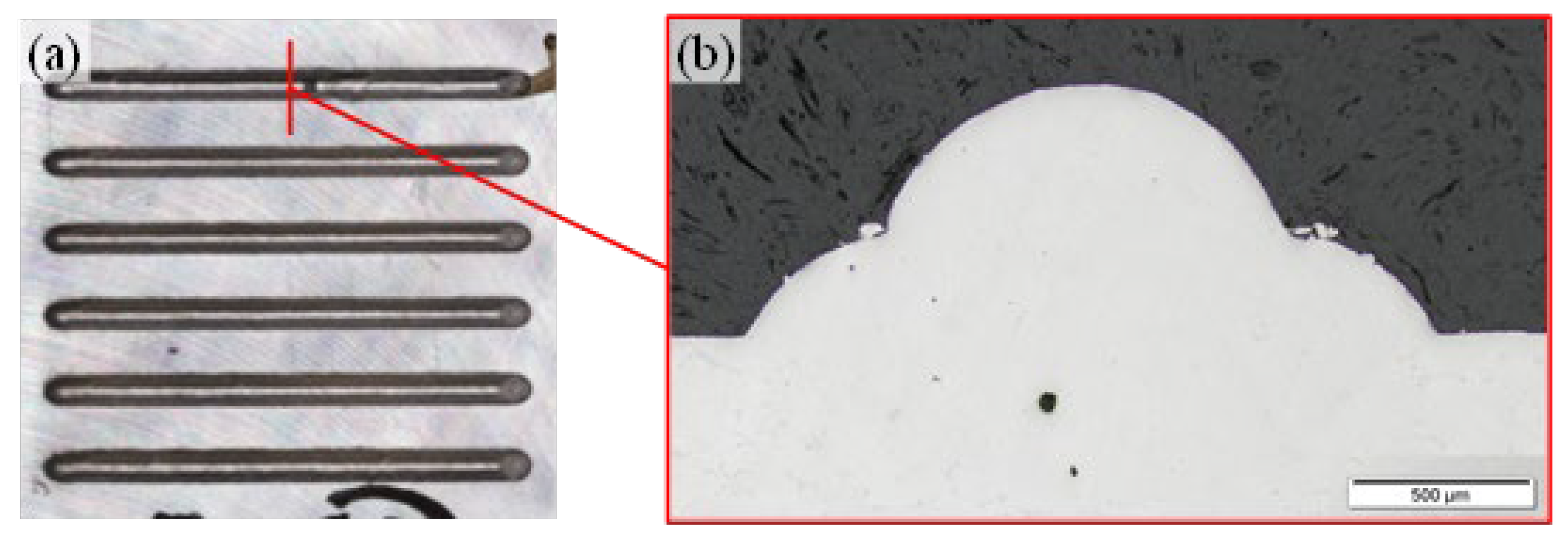
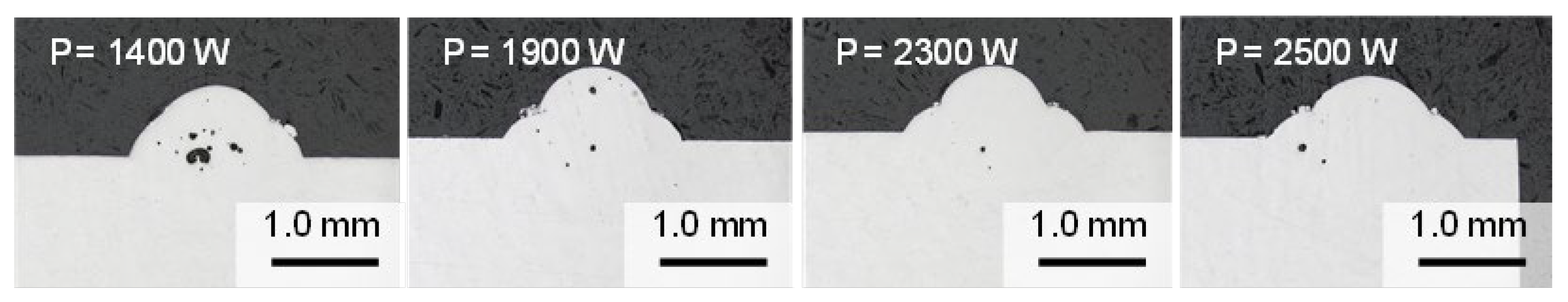
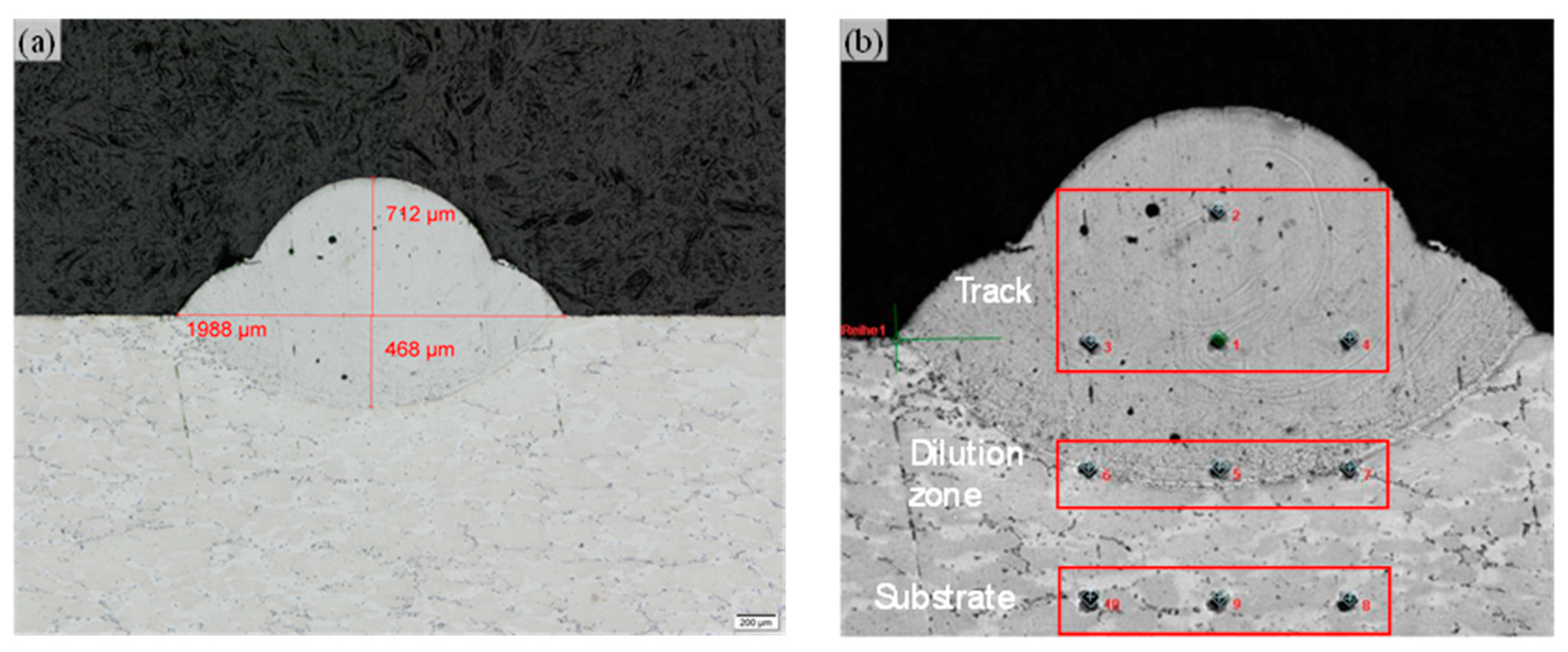
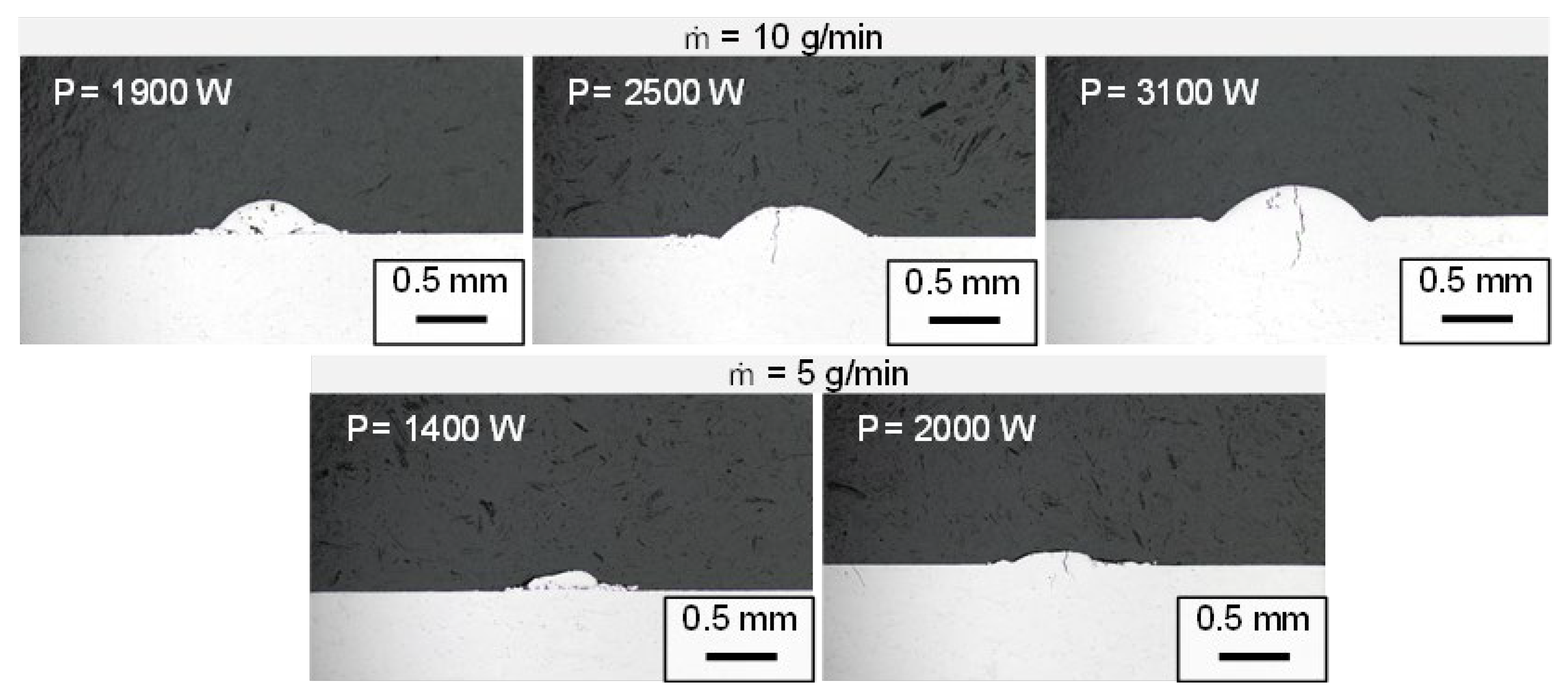
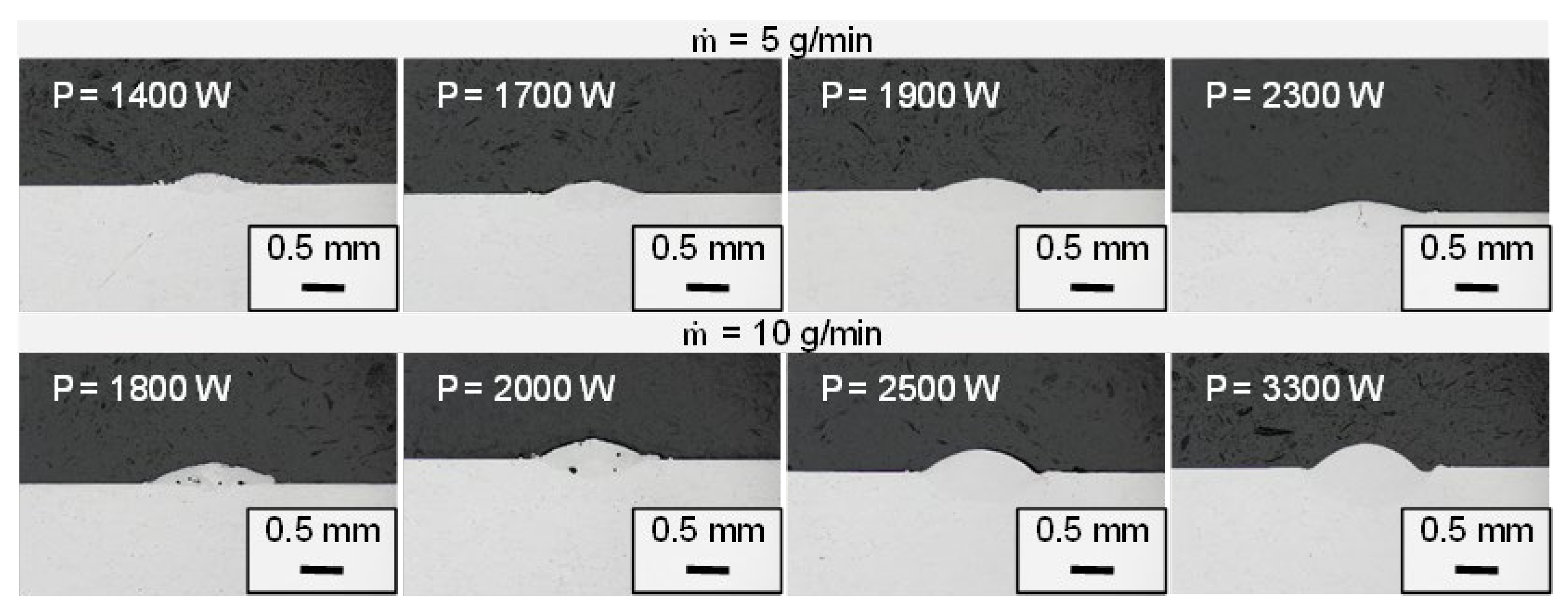
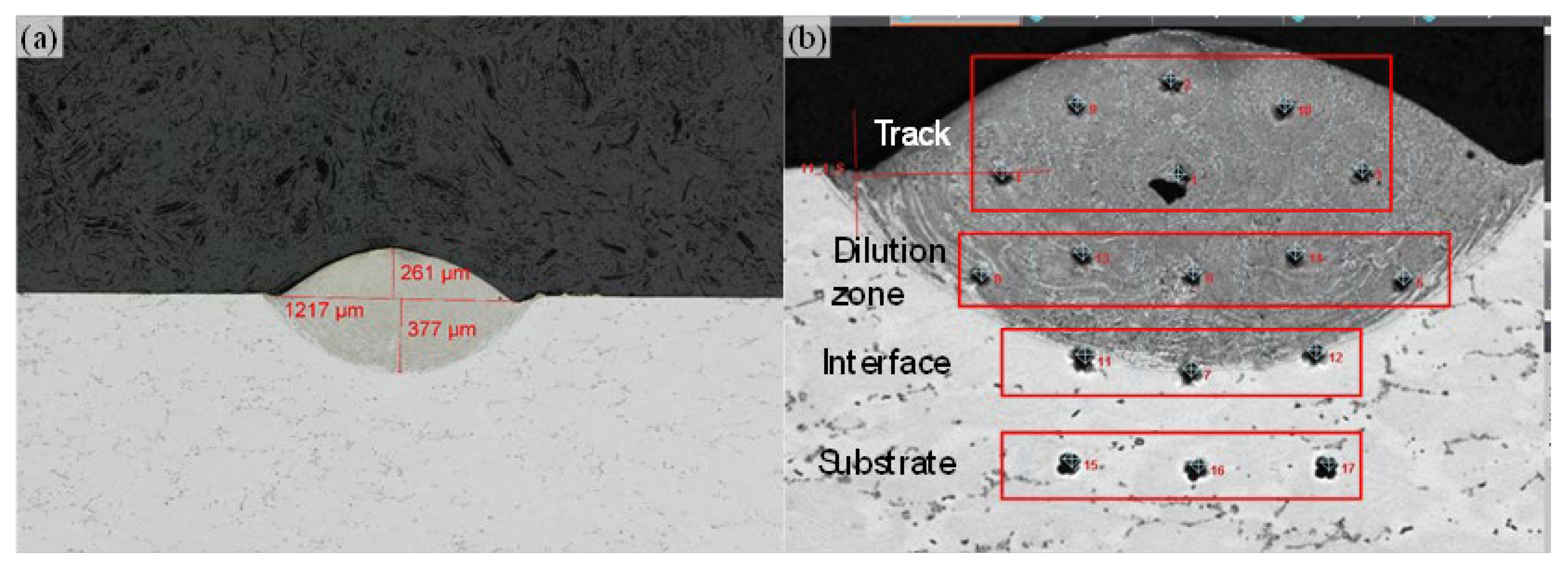
3.1. Single-Track Process Parameter Study

Bonding between the repair layer and substrate was evaluated through metallographic examination of cross-sections. We assessed the continuity of the interface, presence of defects, and the extent of the heat-affected zone.
Within the initial LP-DED parameter study, the beam power varied between 1000 W ≤ P ≤ 2500 W in 100 W increments. The results indicate that a minimum beam power of P = 1100 W is required for sufficient metallurgical bonding. Below this beam power threshold, the deposited single tracks are either partly or not bonded to the substrate material. The variation in the beam power indicates that the applied beam power affects the pore formation within the deposited track (see Figure 5).
After sufficient metallurgical bonding can be assured with an applied beam power threshold, a lower beam power tends to result in more and bigger pore formation. Increasing the beam power reduces the size and number of pores; however, within the study, pore formation could not be fully avoided. After the minimum pore size and number at P = 2300 W, the pores tend to increase with higher beam power. A possible mechanism for this tendency is that already formed pores can dissolve and diffuse out of the melt pool at higher melt pool temperatures, resulting in lower melt pool viscosity and slower solidification time. Too high of a beam power can result in turbulent melting pools, which might enclose more pores. Based on the initial study, the parameter set with the beam power of P = 2300 W is selected for the further repair evaluation. The qualitative evaluation of the microstructure indicates the Al-matrix with the Mg2Si precipitates of the T6 Al6061 substrate. The deposited weld track as well as the dilution zone have a homogenous microstructure with no evident grain formation and precipitation (see Figure 6a). For the material property evaluation, hardness measurement is conducted in the weld bead, dilution zone, and substrate material (see Figure 6b).
According to the hardness measurement, the T6 heat treated Al6061 substrate has an initial hardness value of 86 ± 3.7 HV. Due to a missing heat treatment, the as-deposited single track has a lower hardness value (see Table 5). Due to this and depending on the end specification, a component repaired by LP-DED can require heat treatment as an additional post-processing step.
Within this study, all Al6061 single tracks deposited by EHLA have critical defects, like insufficient bonding or solidification cracks. The solidification cracks are formed vertically through the whole weld bead and dilution zone (see Figure 7) and indicate that the rapid solidification effect of the EHLA process is not beneficial for the Al6061 alloy.
Because of this, the single-track study was continued with the alloy AlSi10Mg, which is a typical Al-alloy for additive manufacturing, compatible with the Al6061 substrate, as defect-free single tracks could be deposited at both ṁ = 5 g/min and ṁ = 10 g/min (see Figure 8).
As shown in Figure 8, due to the higher powder mass flow, single tracks deposited with ṁ = 10 g/min generally have a bigger weld bead geometry than the single tracks deposited with ṁ = 5 g/min. Solidification cracks are formed when a beam power of P > 2300 W and a lower powder feed rate of ṁ = 5 g/min are applied. Tendencies in pore formation can be identified when a higher powder mass flow of ṁ = 10 g/min and lower beam power of P = 2000 W are applied. Like LP-DED, the enclosure of pores can be mitigated when the melt pool temperature is increased by using higher beam power. For the repair application, the process parameter set with P = 2500 and ṁ = 10 g/min is selected for a higher rate of productivity. According to the etched cross-section, the depth of the dilution zone is ~ 100 µm higher than the deposited weld bead, which can result in the mixture of the Al-alloys and a change in the material properties. For the evaluation of the material properties, hardness tests were conducted similar to the LP-DED single track (see Figure 9).
According to the hardness test results (see Table 6), the hardness of the deposited single track exceeds the hardness of the substrate material at an as-built state by ~100 HV. This indicates that no heat treatment of a repaired component is required as an additional post-processing step. The hardness in the dilution zone is comparable to the hardness of the substrate. At the interface zone, the hardness reaches a minimum at 80 HV, which indicates the local dilution of both alloys.

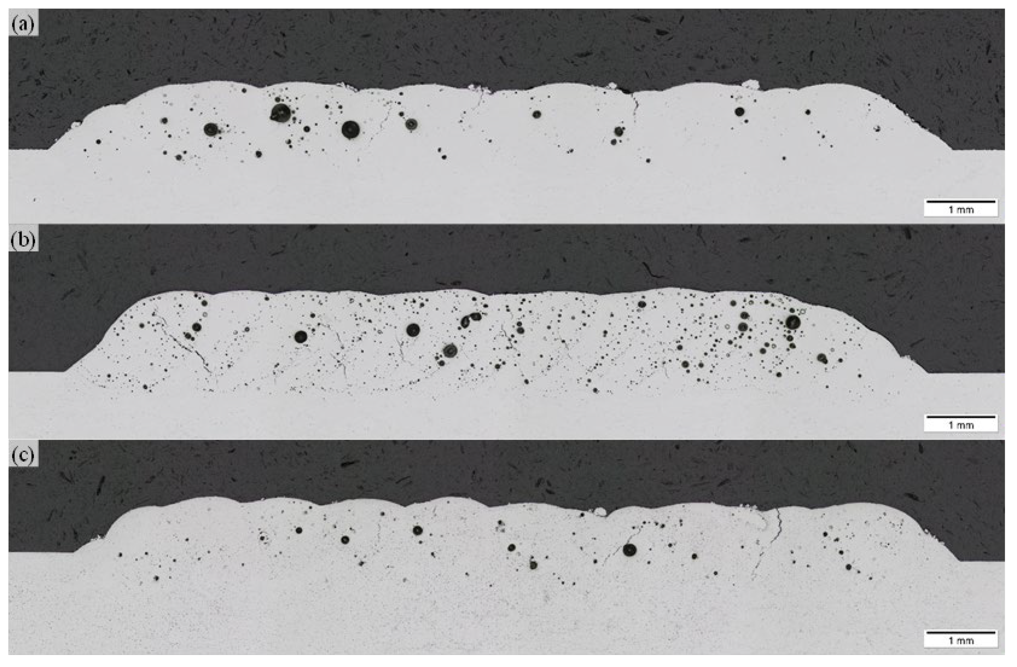
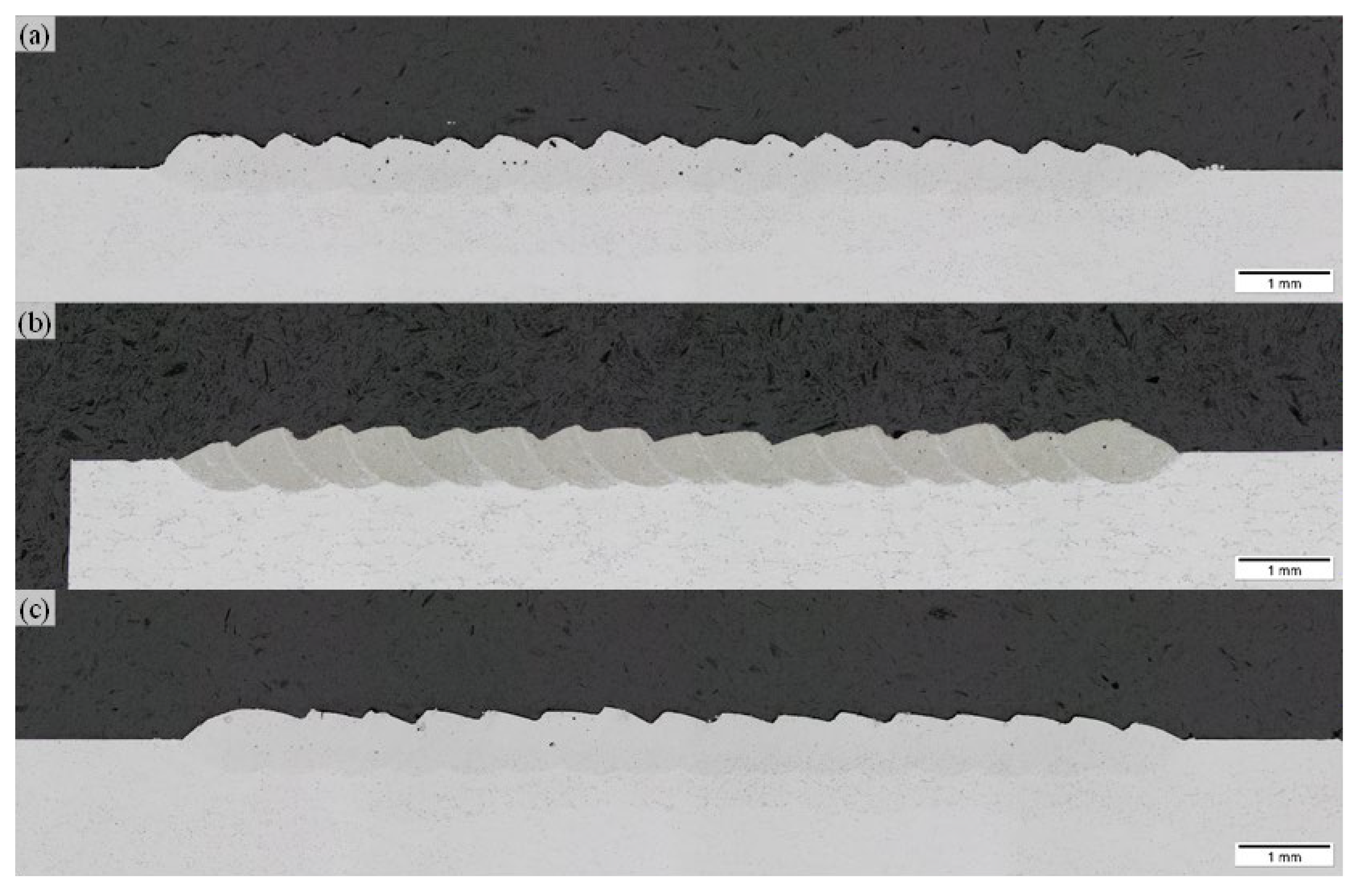
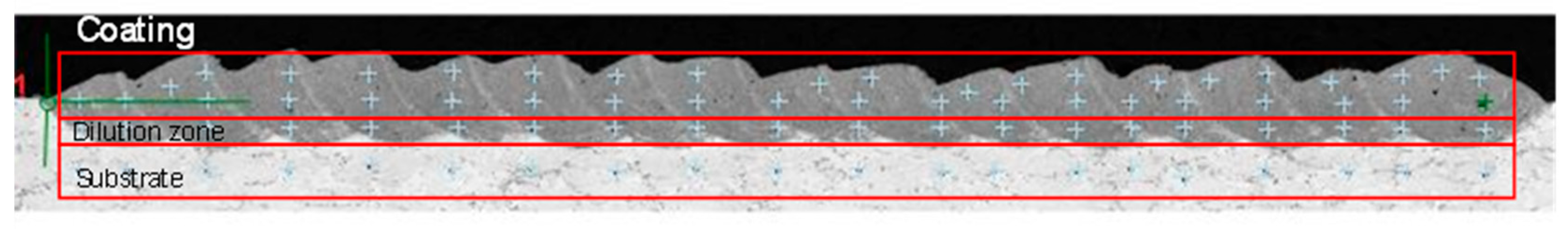
3.2. Coating Process
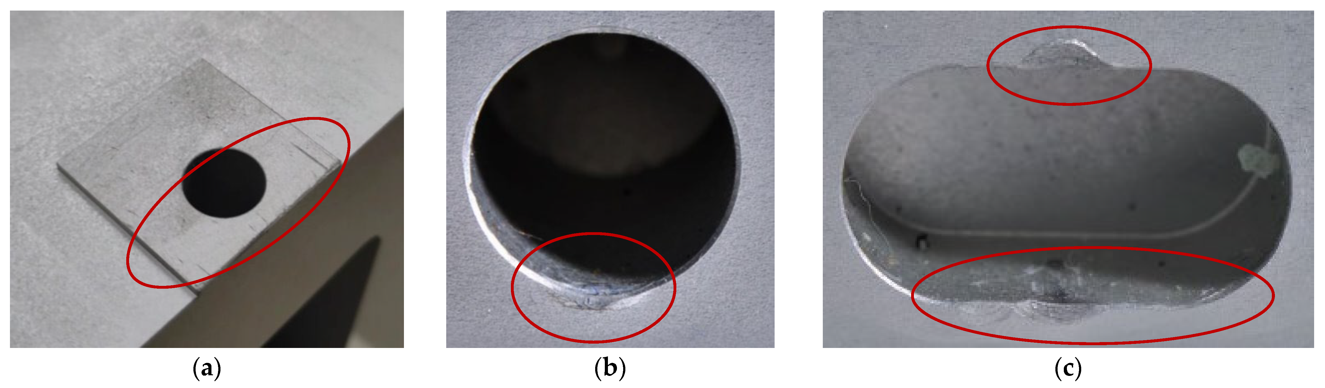
In the second phase, process parameters from the single-track phase were selected for the deposition of single-layer coatings to investigate the repair of extended defects, like dents and scratches. The process parameters listed in Table 7 were selected for the single-layer analysis.
For the LP-DED single-layer coating, the applied hatch distances were varied by 40%, 50%, and 60% track overlap (see Figure 10). Although the LP-DED single track has no critical defect formation, the coating specimens have a considerable higher porosity as well as cracks. Larger pores possibly caused by keyhole collapse occurred because of the vaporization from an excessively focused laser, where gas bubbles appear. Small pores, similar to the ones appearing at the single-track deposition, are caused by gas entrapment. The pores are particularly formed at the interfaces of each overlapping weld bead, a particularity also observed by A. Wang et al. [27]. Similar to their results, a reduction in pore segregation is observed by increasing the hatch spacing. Due to this, further investigations regarding adapted path-planning strategies and process parameters are required for a defect-free deposition with LP-DED.
In contrast to the LP-DED process, a defect-free layer deposition is feasible by using the EHLA process and AlSi10Mg alloy (see Figure 11). The parameter sets P = 2600 W and P = 2900 W results in a nearly defect-free coating. Statistically distributed pores can be identified at P = 2500 W. For the evaluation of the material properties, hardness tests were conducted with the coating resulting from the parameter set with P = 2600 W (see Figure 12).
Similar to the single track, the hardness of the coating exceeds the hardness of the substrate material (see Table 8). In addition to that, the hardness of the dilution zone stays in the same range as the substrate material. This indicates that a repair process can still be conducted for larger defects by applying the EHLA process.

4. Case Study

The purpose of this section is to test the new repair process for a 6061 aluminum component. The spacer component holds critical distance in the machine. During installation it comes in contact with stainless steel parts, and critical surfaces are scratched, and small dents appear around milled pockets; therefore, the component is rejected and replacement with a new one is required. As aluminum milling is both time- and cost-efficient, the manufacturer prefers replacement over repair. However, the demonstration of the repair can also open the door for larger, high-value component identification in large assemblies, where a localized LP-DED/EHLA-repair of aluminum does add value. After visual inspection, the damages shown in Figure 13 were identified for repair.
As the damage sizes are in the range of 0.1–1 mm in depth, a preprocessing milling operation was necessary to prepare a more accessible deposition area around the edge dents and ensure necessary bonding with the substrate. The 30 mm × 30 mm surface was entirely preprocessed. (Figure 14) For the surface repair, the AlSi10Mg powder was EHLA-deposited using two layers. For the deposition, argon gas was used as the carrier and shielding gas, with a carrier gas flow of QC = 8 l/min and a shielding gas flow of QS = 12 l/min. The component was fixed horizontally, and the single track was deposited with a 50% overlay.
The LP-DED deposition approach was tested to repair the pocket dents, as shown on Figure 15. The toolpaths were deployed manually, iteratively programming several single-track depositions. For the LP-DED repair of the edge dent, the Al6061 powder was used.
The component was fixed at a 45° tilted position for better deposition head access and to ensure a 90° deposition angle to the processing surface. As an initial demonstration, the surface gradients at the edge of the chamfers were neglected within this study. To obtain the original geometry, a post-processing milling operation is performed (see Figure 16).
After the post-processing, most of the filled surface area is defect-free; however, pore formation can be identified at the edge areas of the filled chamfer, marked in the red circles from Figure 16. The pore formation is likely caused by a non-perpendicular deposition condition caused by the simple and manual single-track path planning. At later stages and maturation of the process chain, an automated path planning, which considers the gradient at the chamfer areas, potentially avoids the defect formation at the edge areas. Still, a potential repair process for Al components is conceptually demonstrated as most of the filled surface area is defect-free.

5. Conclusions

The new process parameters and improved LP-DED/EHLA capabilities were tested and validated for competitive repairing of the Al 6061 components with three different types of damages.
  • Our results highlight the potential of both LP-DED and EHLA techniques to deposit AlSi10Mg powder onto Al 6061 substrate, with the aim of repairing aluminum 6061 components. Especially EHLA shows good prospects for repairing surface defects due to its higher precision and speed.
  • The Vickers measurement demonstrates increased microhardness (100 HV) of EHLA-deposited tracks for AlSi10Mg powder, compared to the Al6061 substrate (81 HV). To measure and adequately compare the microhardness of EHLA-deposited Al6061 tracks, further development of the process parameters is needed, considering the effects of surface treatment on microhardness.
  • The EHLA deposition of Al6061 presents microcracks already in the single-track deposition. No defects were registered in our experiments with AlSi10Mg powder on the Al6061 substrate. Increased beam powers between P = 2600–2900 W result in crack- and pore-free single beads and single layers.
  • For the Al6061 powder, based on single-track analysis, defect-free tracks were obtained in the LP-DED deposition, with vtool = 2 m/min, powder mass flow of 5 g/min, and laser power between 1900–2500 W.
  • The initial investigation of repairing damages indicates a feasible repairing process of Al parts by LP-DED and EHLA technologies. However, there are other factors influencing the pore formation, such as heat transfer and surface conditions, which require further research. Future work should focus on advanced path-planning strategies, in situ monitoring, and adaptive control to mitigate porosity in complex geometries.

Author Contributions

Conceptualization, A.M. and M.-U.K.; methodology, M.-U.K. and R.K.; software, M.-U.K.; validation, A.M. and M.-U.K.; formal analysis, A.M. and M.-U.K.; investigation, A.M. and M.-U.K.; resources, A.M. and M.-U.K.; data curation, M.-U.K. and R.K.; writing—original draft preparation, A.M.; writing—review and editing, M.-U.K. and N.B.; project administration, A.M.; funding acquisition A.M. All authors have read and agreed to the published version of the manuscript.

Funding

This research was funded by Capgemini Engineering Netherlands, under internal PO. 4130024464, as part of a bilateral cooperation between Capgemini Engineering Netherlands and Fraunhofer ILT.

Data Availability Statement

Data are contained within the article.

Acknowledgments

The authors would like to thank Capgemini Engineering Netherlands’ management team for making this work possible and the Fraunhofer ILT’s facility for strongly supporting this work.

Conflicts of Interest

The authors declare no conflicts of interest. The funders had no role in the design of the study; in the collection, analyses, or interpretation of data; in the writing of the manuscript; or in the decision to publish the results.

Abbreviations

The following abbreviations are used in this manuscript:
AlAluminum
DEDDirected Energy Deposition
EHLA Extreme High-Speed Directed Energy Deposition
LPBFLaser Powder Bed Fusion
LP-DED Laser-powder Directed Energy Deposition

References

  1. Liu, M.; Wei, K.; Zeng, X. High power laser powder bed fusion of AlSi10Mg alloy: Effect of layer thickness on defect, microstructure and mechanical property. Mater. Sci. Eng. 2022, 842, 143107. [Google Scholar] [CrossRef]
  2. Andersson, O.; Graichen, A.; Brodin, H.; Navrotsky, V. Developing Additive Manufacturing Technology for Burner Repair. J. Eng. Gas Turbines Power 2016, 139, 031506. [Google Scholar] [CrossRef]
  3. Sato, N.; Matsumoto, M.; Ogiso, H.; Sato, H. Challenges of Remanufacturing Using Powder Bed Fusion Based Additive Manufacturing. Int. J. Autom. Technol. 2022, 16, 773–782. [Google Scholar] [CrossRef]
  4. Priscopo, G.; Atzeni, E.; Saboori, A.; Salmi, A. An Overview of the Process Mechanisms in the Laser Powder Directed Energy Deposition. Appl. Sci. 2023, 13, 117. [Google Scholar] [CrossRef]
  5. Ko, M.-U.; Zhang, Z.; Schopphoven, T. Process development and process adaptation guidelines for the deposition of thin-walled structures with IN718 using extreme high-speed directed energy deposition (EHLA3D). J. Laser Appl. 2023, 35, 042059. [Google Scholar] [CrossRef]
  6. Schopphoven, T.; Gasser, A.; Backes, G. EHLA: Extreme High-Speed Laser Material Deposition, Economical and effective protection agains corrosion and wear. Laser Tech. J. 2017, 14, 26–29. [Google Scholar] [CrossRef]
  7. Liang, Y. A review on coatings deposited by high-speed laser cladding: Processes, materials and properties. Opt. Laser Technol. 2023, 164, 109472. [Google Scholar] [CrossRef]
  8. Koss, S.; Vogt, S.; Goebel, M.; Schleifenbaum, J.H. Coating of Aluminum with High Deposition Rates through Extreme High-Speed Laser Application. J. Therm. Spray Technol. 2023, 32, 1689–1697. [Google Scholar] [CrossRef]
  9. Guner, A.; Bidare, P.; Jiménez, A.; Dimov, S.; Essa, K. Nozzle design in powder-based direct laser deposition: A review. Int. J. Precis. Eng. Manuf. 2022, 23, 1077–1094. [Google Scholar] [CrossRef]
  10. DIRECT ENERGY DEPOSITION (LP-DED)—A Comparison of Multiple Metal 3D Printing Methods. Available online: http://www.ramlab.com/resources/ded-101/ (accessed on 10 January 2024).
  11. Schaible, J.; Hausch, D.; Schopphoven, T.; Haefner, C. Deposition strategies for generating cuboid volumes using extreme high-speed directed energy deposition. J. Laser Appl. 2022, 34, 042034. [Google Scholar] [CrossRef]
  12. Kanishka, K.; Acherjee, B. A systematic review of additive manufacturing-based remanufacturing techniques for component repair and restoration. J. Manuf. Process. 2023, 89, 220–283. [Google Scholar] [CrossRef]
  13. Oh, W.J.; Lee, W.J.; Kim, M.S.; Jeon, J.B.; Shim, D.S. Repairing additive-manufactured 316L stainless steel using direct energy deposition. Opt. Laser Technol. 2019, 117, 9–17. [Google Scholar] [CrossRef]
  14. Perini, M.; Bosetti, R.; Balc, N. Additive manufacturing for repairing; from damage identification and modeling to DLD. Rapid Prototyp. J. 2020, 26, 929–940. [Google Scholar] [CrossRef]
  15. Xu, H.; Zhang, Q.; Tian, T.; Niu, L.; Li, H.; Han, B.; Zhu, H.; Wang, X. In-situ hot rolling directed energy deposition-arc repair of shafts. Addit. Manuf. 2023, 61, 103362. [Google Scholar] [CrossRef]
  16. Zhang, Y.; Lan, L.; Shi, Q. Microstructural evaluation and precipitated phase characteristics in the fusion zone for the as-repaired Inconel 718 alloy by directed energy deposition additive manufacturing. Mater. Charact. 2023, 204, 113222. [Google Scholar] [CrossRef]
  17. Rosito, M.; Vanzetti, M.; Padovano, E.; Gili, F.; Sampieri, R.; Bondioli, F.; Badini, C.F. Processability of A6061 Aluminum Alloy Using Laser Powder Bed Fusion by In Situ Synthesis of Grain Refiners. Metals 2023, 13, 1128. [Google Scholar] [CrossRef]
  18. Büßenschütt, K.; Köhnen, P.; Kies, F.; Koß, S.; Schleifenbaum, J.H.; Haase, C. High-Speed direct energy deposition as a high-throughput design tool for laser-based additive manufacturing. Addit. Manuf. Lett. 2024, 8, 100188. [Google Scholar] [CrossRef]
  19. Li, T.; Zhang, D.; Zhang, L.; Schopphoven, T.; Gasser, A.; Poprawe, R. Thermal features and its effect on the properties of AISI 4140 fabricated by conventional and extreme high-speed laser material deposition. J. Manuf. Process. 2024, 131, 1372–1387. [Google Scholar] [CrossRef]
  20. What is Exteme High-Speed Laser Application? (EHLA); Technical Data of TWI Ltd.: Cambridge, UK; Available online: https://www.twi-global.com/technical-knowledge/faqs/what-is-ehla (accessed on 26 July 2025).
  21. Madarieta-Churruca, M.; Arrizabalaga, J.L.; Garmendia-Sáez-de-Heredia, I.; Soriano, C. Comparative Study of Laser metal deposition (LMD) of coaxial wire and powder in the manufacture of Ti-6Al-4V structures. Dyna 2020, 95, 376–379. [Google Scholar] [CrossRef] [PubMed]
  22. Lv, F.; Shen, L.; Liang, H.; Xie, D.; Wang, C.; Tian, Z. Mechanical properties of AlSi10Mg alloy fabricated by laser melting deposition and improvements via heat treatment. Opt. Int. J. Light Electron Opt. 2019, 179, 8–18. [Google Scholar] [CrossRef]
  23. Hermann, F.; Vogt, S.; Göbel, M.; Möller, M.; Frey, K. Laser Metal Deposition of AlSi10Mg with high build rates. Procedia CIRP 2022, 111, 210–213. [Google Scholar] [CrossRef]
  24. Li, J.; Liu, Z.; Ning, H.; Ma, H.; Xie, R.; Kong, Y.; Fu, Y. Ni-based coating on 5083 Aluminum alloy with Cu-Ni interlayer fabricated by ultra-high-speed laser directed energy deposition. Surf. Coat. Technol. 2023, 474, 130068. [Google Scholar] [CrossRef]
  25. Dong, E.; Chang, T.; Zhao, L.; Xing, Y.; Chen, J.; Chen, M.; Lu, J.; Cheng, J. Laser metal deposition of AlSi10Mg for aeroengine casing repair: Microhardness, wear and corrosion behavior. Mater. Today Commun. 2024, 38, 108412. [Google Scholar] [CrossRef]
  26. Ferreira, N.M. Direct Energy Deposition Parametric Simulation Investigation in Gear Repair Application. Materials 2023, 16, 3549. [Google Scholar] [CrossRef]
  27. Wang, A.; Wei, Q.; Tang, Z.; Oliveira, J.P.; Leung, C.L.A.; Ren, P.; Zhang, X.; Wu, Y.; Wang, H.; Wang, H. Effects of hatch spacing on pore segregation and mechanical properties during blue laser directed energy deposition of AlSi10Mg. Addit. Manuf. 2024, 85, 104147. [Google Scholar] [CrossRef]
Figure 1. LP-DED and EHLA nozzle types: (a) LP-DED, (b) EHLA, (reproduced based on [4,11]).
Jmmp 09 00255 g001
Figure 2. Experimental setup.
Jmmp 09 00255 g002
Figure 3. (a) Example of LP-DED single tracks; (b) example of metallographic cross-section.
Jmmp 09 00255 g003
Figure 4. Applied path-planning strategy for the single-layer deposition.
Jmmp 09 00255 g004
Figure 5. Single track results: d = 1.2 mm; ṁ = 5 g/min; QC = 8 L/min; QS = 12 L/min.
Jmmp 09 00255 g005
Figure 6. (a) Etched cross-section of the selected LP-DED single track; (b) point indication of conducted hardness measurement.
Jmmp 09 00255 g006
Figure 7. Cross-sections of Al6061 single tracks deposited by EHLA.
Jmmp 09 00255 g007
Figure 8. AlSi10Mg single tracks deposited by EHLA.
Jmmp 09 00255 g008
Figure 9. (a) Etched cross-section of the selected EHLA single track; (b) point indication of conducted hardness measurement.
Jmmp 09 00255 g009
Figure 10. Cross-sections of Al6061 LP-DED single-layer coating (a) hatch = 40%; (b) hatch = 50%; (c) hatch = 60%.
Jmmp 09 00255 g010
Figure 11. Cross-section of AlSi10Mg EHLA single-layer coating with 50% track overlap as hatch distance (a) P = 2500 W; (b) P = 2600 W—etched; (c) P = 2900 W.
Jmmp 09 00255 g011
Figure 12. Point indication of conducted hardness measurement.
Jmmp 09 00255 g012
Figure 13. Preprocessed areas: (a) surface milling, (b) dent milling, (c) dent milling.
Jmmp 09 00255 g013
Figure 14. (a) Machine setup for EHLA repair; (b) EHLA deposition before post-processing.
Jmmp 09 00255 g014
Figure 15. (a) Tilted machine setup for EHLA repair; (b) setup for LP-DED repair; (c) filling of milled chamfer with LP-DED single tracks.
Jmmp 09 00255 g015
Figure 16. (a) Post-processed surface area; (b) + (c) post-processed pockets with pores at the edge areas of the chamfer.
Jmmp 09 00255 g016
Table 1. Technology performance comparison.
Aspects LP-DEDEHLAReferences
Application Freeform 3D geometry manufacturing;
multi-material structures;
coating and repair.
Coating and repair;
thin-wall structures.
[5,6,7,8,9,12,13,14,15,16]
Feed rate 0.2–2 m/min>20 m/min, up to 100 m/min [9,17]
Layer thickness 200–1000 µm 30–300 µm[5,13]
Heat affected zone (dissipation) 100–500 µm10–100 µm[18,19]
Powder catchment efficiencyAround 70%Around 90% [20,21]
Table 2. Chemical composition of Al6061 according to EN AW-6061.
Material [%]AlSiMgFeTiZnMnCuCrOEOT
Bal.0.4–0.80.8–1.2≤0.7≤0.15≤0.25≤0.150.15–0.40.04–0.35≤0.05≤0.15
Table 3. Process parameter combinations for single-track analysis.
dbeam [mm]V [m/min]P [W]ṁ [g/min]
LP-DED
1.221000–25005
EHLA-Al6061
1.220900–2000 5
1000–3100 10
EHLA–AlSi10Mg4
1.220800–2500 5
1200–3300 10
Table 4. Process parameter combinations for single-layer analysis.
dbeam [mm]V [m/min]P [W]ṁ [g/min]Hatch [mm]
LP-DED–Al6061
1.22230050.8
1.0
1.2
EHLA–AlSi10Mg
1.2202500100.60
26000.65
29000.65
Table 5. Hardness measurement results of LP-DED single track.
TrackDilution ZoneSubstrate
71 ± 1.9 HV77 ± 9.3 HV86 ± 3.8 HV
Table 6. Hardness measurement results of EHLA single track.
TrackDilution ZoneInterfaceSubstrate
103 ± 9.3 HV89 ± 3.0 HV80 ± 4.3 HV91 ± 0.3 HV
Table 7. Single-layer deposition parameters.
dbeam [mm]V [m/min]P [W]ṁ [g/min]QC [L/min]QS [L/min]
LP-DED–Al6061
1.2223005812
EHLA–AlSi10Mg4
1.220250010812
2600
2900
Table 8. Hardness measurement result of the EHLA coating.
CoatingDilution ZoneSubstrate
91 ± 3.1 HV89 ± 4.5 HV87 ± 6 HV
Disclaimer/Publisher’s Note: The statements, opinions and data contained in all publications are solely those of the individual author(s) and contributor(s) and not of MDPI and/or the editor(s). MDPI and/or the editor(s) disclaim responsibility for any injury to people or property resulting from any ideas, methods, instructions or products referred to in the content.

