
An Overview of the Working Conditions of Laser–Arc Hybrid Processes and Their Effects on Steel Plate Welding

 ,
,  ,
,  , and
, and 
Abstract
1. Introduction
1.1. Arc Welding Processes
1.2. Laser Beam Welding
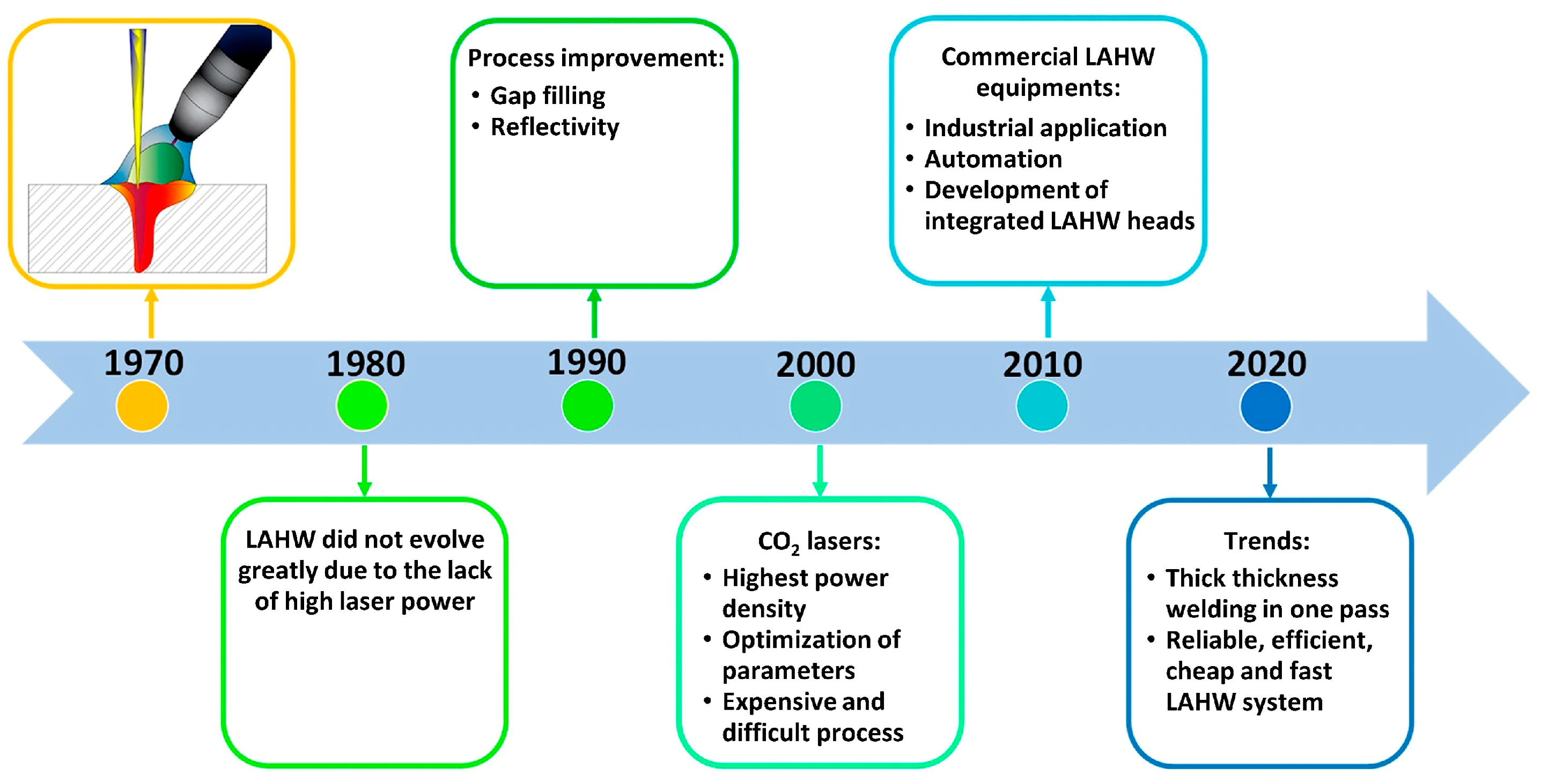
1.3. Laser–Arc Hybrid Process
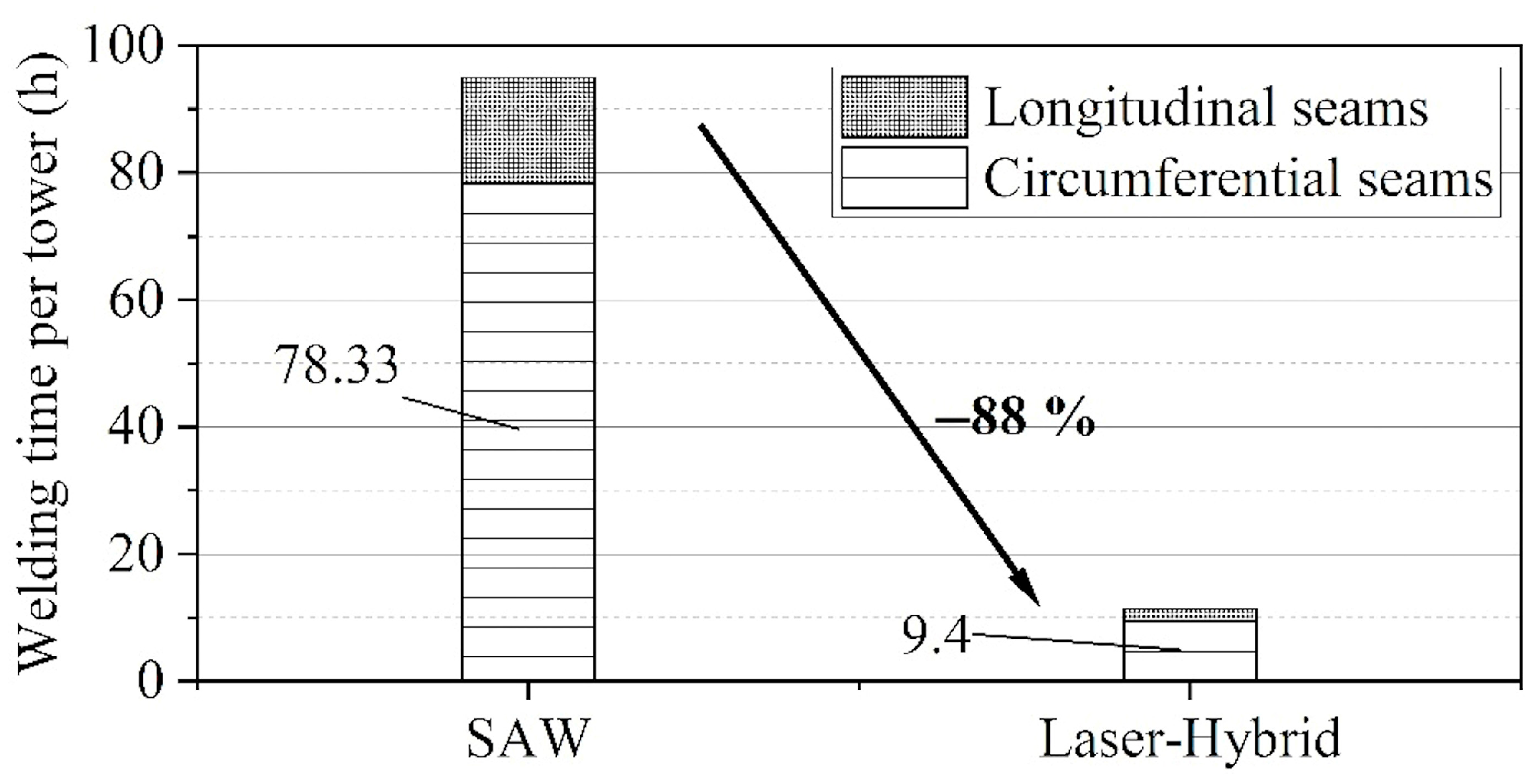
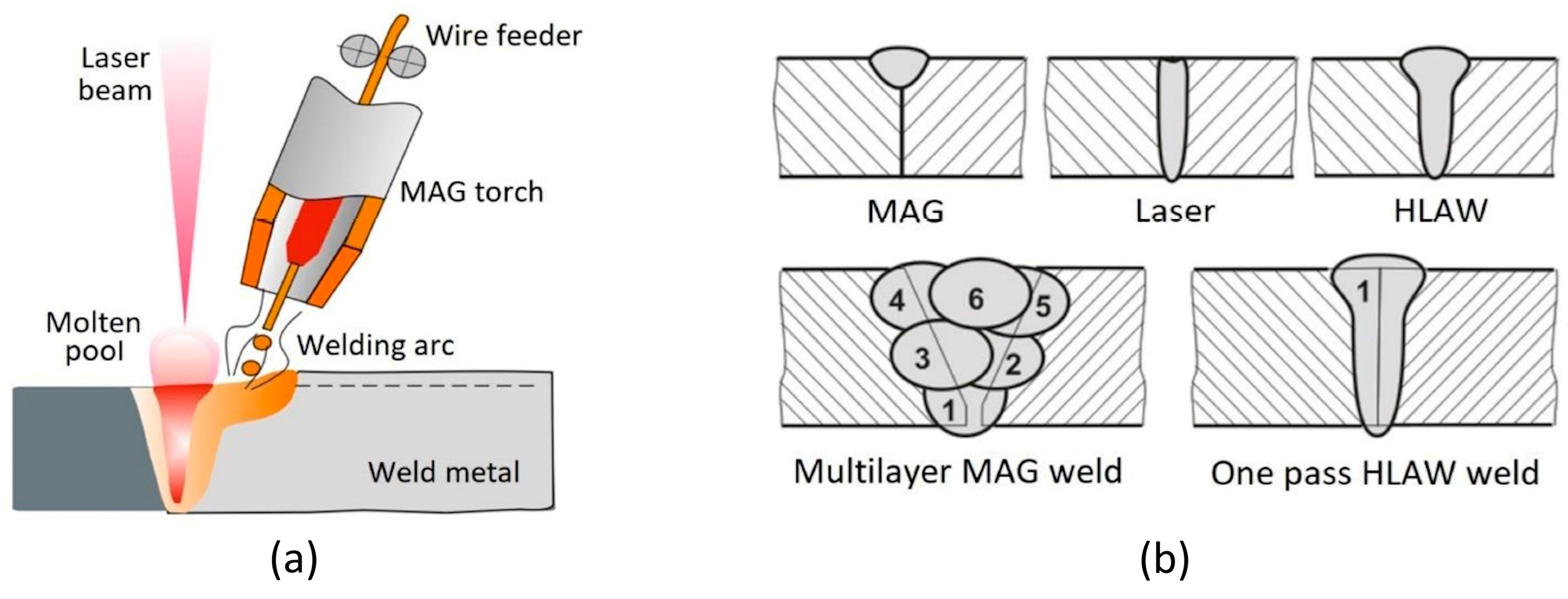
- Thick plates can be joined using single-pass LAHW [22], overcoming the re-heating and re-melting issues that affect the multiple passes of a typical arc welding process.
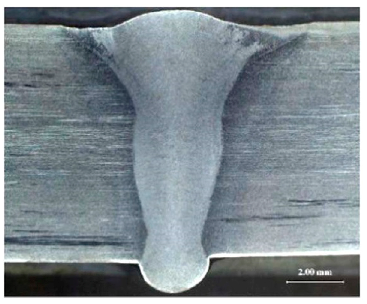
- The upper zone of the weld is predominantly influenced by the electric arc, while deep penetration is due to the keyhole action of the laser [23].
- LAHW results in high filling efficiency of the consumable electrode, and, in general, the welds exhibit better properties in comparison to technologies adopting only one heat source [24].
- Given the greater tolerance for misalignments exhibited by the electric arc, LAHW demonstrates superior bridgeability in comparison to LBW [25].
- The heat input due to the electric arc lowers the cooling rate, leading to reduced hardness compared to autogenous LBW [1].
- Residual stress can also be significantly reduced in comparison with the traditional arc welding techniques [26].
2. System Configuration (Laser- or Arc-Leading)
2.1. Laser-Leading Configuration
2.2. Arc-Leading Configuration
3. Effects of Welding Parameters
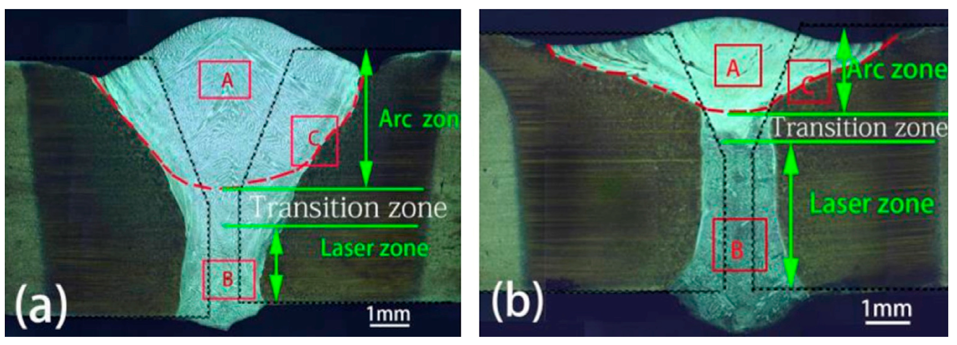
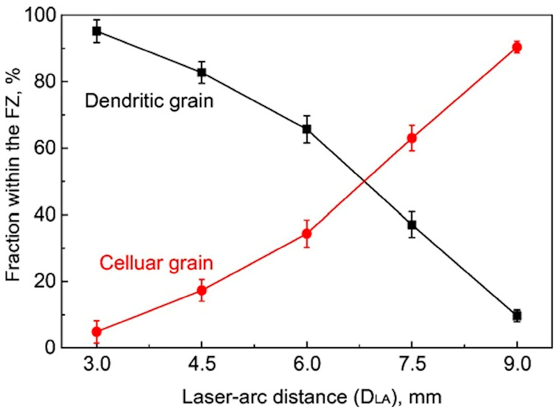
3.1. Effects of Laser–Arc Inter-Distance
3.1.1. Low Inter-Distance (Hybrid Mode)
3.1.2. High Inter-Distance (Tandem Mode)
3.2. Effects of Heat Input and Power Ratio
3.3. Effects of Laser Beam Parameters on Penetration Depth
3.4. Combined Effects of Laser Power and Arc Current
3.5. Effects on Pore Formation
3.6. Effects of Welding Speed
3.7. Effects of Filler Transfer Conditions
3.8. Effects of Shielding Gas
3.9. Effects of Edge Geometry and Gap
3.10. Hybrid Process Modeling
3.11. Final Remarks on Parameters’ Settings and Process Control
4. Weld Solidification Issues
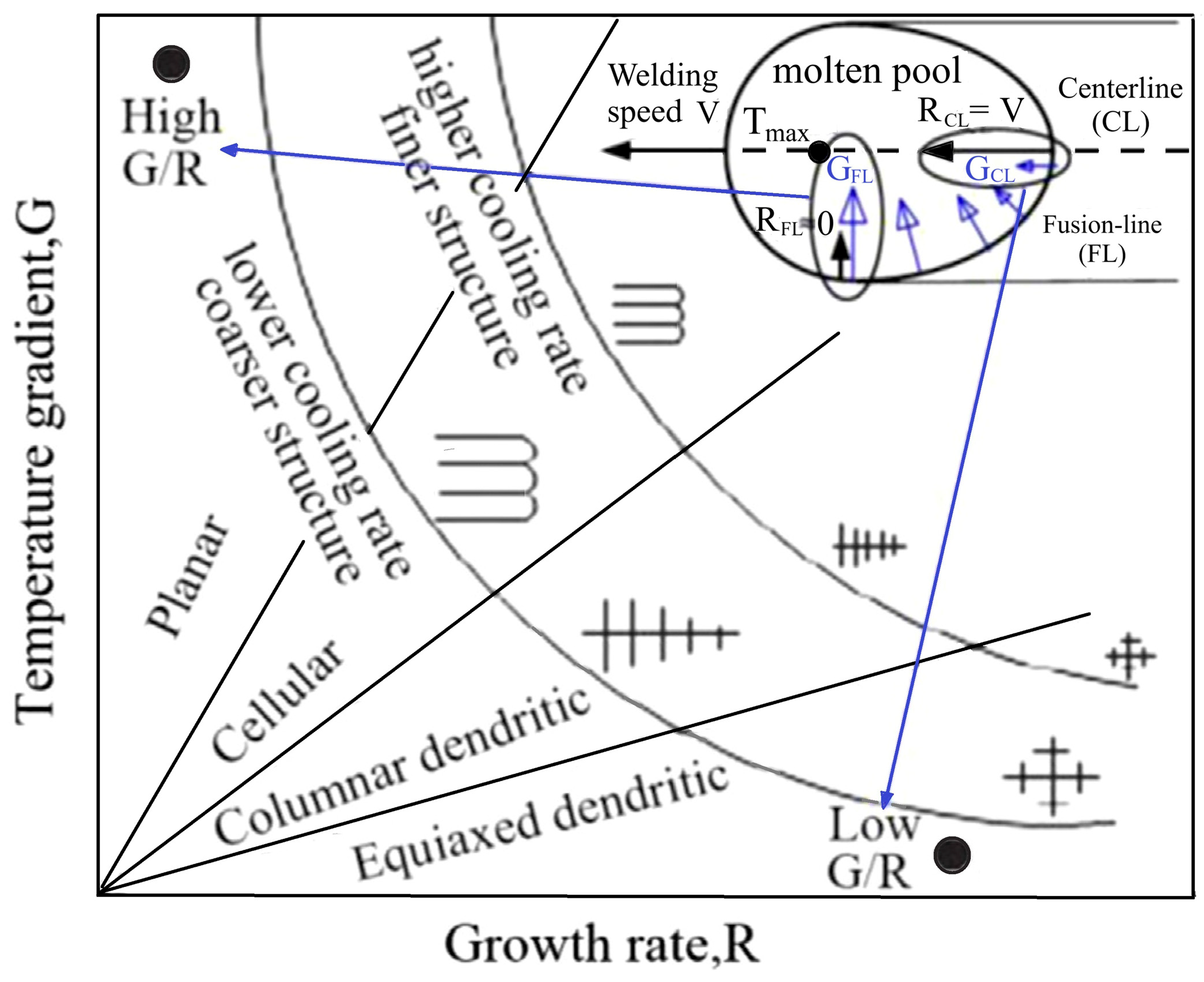
4.1. Solidification Modes
4.2. Weld Composition
5. Laser–Arc Welding of Clad Steel
6. Conclusions and Future Developments
- From a technological point of view, the development of integrated laser–arc heads at low costs is desirable to allow for greater diffusion of this welding method.
- Technological improvements could also have a beneficial effect on the environmental efficiency of the process, which, although promising based on the results of the first studies, deserves further investigation considering the ever-increasing importance of sustainability nowadays in the field of high-intensity manufacturing processes, such as welding.
- From the state of the art analyzed, a common approach emerges in analyzing the effect of sources’ interaction on the final joint, which is primarily based on experimental investigations and sometimes strengthened by numerical simulations. An in-depth study of the complex combination of multiphysical phenomena involved in sources’ interactions is needed to outline the principles underlying their effects and predict weld joint properties.
- Among the thermophysical phenomena that contribute in a particularly complex way to hybrid technologies, further research should be addressed to studying the coupled effects between laser–arc hybrid plasma and the molten pool, which are crucial for the generation of welding defects, such as porosity, undercuts, humps, and spatters, all closely connected to the set of welding parameters.
- In more general terms, a key issue to consider is the most effective method to approach the evaluation of the thermal fields to foresee the effects of the hybrid process modes. Such a procedure would enable metallurgical and mechanical predictions, also in relation to the generation of residual stresses.
- Due to the complexity of the phenomena during solidification, weld metallurgy requires targeted investigations. In this regard, some issues not thoroughly studied, such as filler and base materials’ composition, as well as melt pool shape and the cooling rate due to the welding conditions, are crucial and deserve to be further explored. An example is the welding of austenitic clad plates. In this case, some authors have demonstrated the advantage of distinguishing the arc and laser zones in order to concentrate the filling action of the electric arc in the cladding layer, differentiating the microstructure of the joint (austenitic at the cladding level, where the filling action prevails) from the ferritic one of the base steel.
- The wide variety of process parameters in LAHW and the ways in which they can be combined make the identification of rational correlations among them and their effects on joint properties a very complex challenge that requires further effort to outline effective supports for the optimization of parameter settings according to the requirements of each specific application. Investigations on quantitative correlations between the main parameters and their effects could make it possible to define ranges of reference values that are significant and reliable as a guide for practitioners in industrial applications.
- Lastly, the new frontiers of artificial intelligence, machine learning, and digital modeling open up wide possibilities in the evolution of welding technologies towards more intelligent and adaptive processes. It is reasonable to imagine that the integration of established welding technologies and advanced digital tools can contribute to the development of more proactive and efficient approaches to welding process setting. In this way, hybrid welding could be improved for specific applications and its potential use extended to a wide range of industrial fields.
Author Contributions
Funding
Data Availability Statement
Conflicts of Interest
References
- Acherjee, B. Laser arc hybrid welding. In Advances in Laser Materials Processing: Technology, Research and Applications, 2nd ed.; Lawrence, J., Ed.; Woodhead Publishing: Kidlington, UK, 2018; pp. 203–234. [Google Scholar]
- Steen, W.M.; Eboo, M.; Clarke, J. Arc Augmented Laser Welding. In Proceedings of the 4th International Conference on Advances in Welding Processes, Harrogate, UK, 9–11 May 1978; Volume 1, pp. 257–265. [Google Scholar]
- Petring, D.; Fuhrmann, C. Recent Progress and Innovative Solutions for Laser-Arc Hybrid Welding. In Proceedings of the 1st Pacific International Conference on Application of Lasers and Optics, Melbourne, Australia, 18–20 April 2004; pp. 7–10. [Google Scholar]
- Churiaque, C.; Chludzinski, M.; Porrua-Lara, M.; Dominguez-Abecia, A.; Abad-Fraga, F.; Sánchez-Amaya, J.M. Laser hybrid butt welding of large thickness naval steel. Metals 2019, 9, 100. [Google Scholar] [CrossRef]
- Bunaziv, I.; Akselsen, O.M.; Frostevarg, J.; Kaplan, A.F.H. Application of laser-arc hybrid welding of steel for low temperature service. Int. J. Adv. Manuf. Technol. 2019, 102, 2601–2613. [Google Scholar] [CrossRef]
- Tang, G.; Zhao, X.; Li, R.; Liang, Y.; Jiang, Y.; Chen, H. The effect of arc position on laser-arc hybrid welding of 12-mm-thick high strength bainitic steel. Opt. Laser Technol. 2020, 121, 105780. [Google Scholar] [CrossRef]
- Emerson, J.N.; Marrero-Jackson, E.H.; Nemets, G.A.; Okuniewski, M.A.; Wharry, J.P. Nuclear reactor pressure vessel welds: A critical and historical review of microstructures, mechanical properties, irradiation effects, and future opportunities. Mater. Des. 2024, 244, 113134. [Google Scholar] [CrossRef]
- Moreno, J.S.; Conde, F.F.; Correa, C.A.; Barbosa, L.H.; Pereira da Silva, E.; Avila, J.; Buzolin, R.H.; Cavalcanti Pinto, H. Pulsed FCAW of martensitic stainless clads onto mild steel: Microstructure, hardness, and residual stresses. Materials 2022, 15, 2715. [Google Scholar] [CrossRef] [PubMed]
- Vairamani, V.; Mohan, N.; Karthikeyan, S.K.; Sakthivel, M. Optimization and microstructure analysis of Corten steel joint in mag welding by post heat treatment. Mater. Today Proc. 2020, 21, 673–680. [Google Scholar] [CrossRef]
- Aninda, R.K.; Karobi, S.M.; Shariar, R.; Rahman, M.M.; Rabby, M.I.I. Effect of post-weld heat treatment on mechanical properties and microstructure in electric arc welded mild steel joints. J. Eng. Res. 2024, 12, 210–215. [Google Scholar] [CrossRef]
- Singh, R. Applied Welding Engineering, 3rd ed.; Butterworth-Heinemann: Oxford, UK, 2020. [Google Scholar]
- Nemova, G. Brief review of recent developments in fiber lasers. Appl. Sci. 2024, 14, 2323. [Google Scholar] [CrossRef]
- Korzhyk, V.M.; Khaskin, V.Y.; Illyashenko, E.V.; Peleshenko, S.I.; Grynyuk, A.A.; Babych, O.A.; Alyoshin, A.O.; Voitenko, O.M. Hybrid laser-plasma welding efficiency and new possibilities (Review). Paton Weld. J. 2024, 1, 13–21. [Google Scholar] [CrossRef]
- Giudice, F.; Missori, S.; Scolaro, C.; Sili, A. A review on fusion welding of dissimilar ferritic/austenitic steels: Processing and weld zone metallurgy. J. Manuf. Mater. Process. 2024, 8, 96. [Google Scholar] [CrossRef]
- Boumerzoug, Z. A review: Welding by laser beam of dissimilar metals. Asp. Min. Miner. Sci. 2021, 8, 916–920. [Google Scholar] [CrossRef]
- Bunaziv, I.; Dørum, C.; Nielsen, S.E.; Suikkanen, P.; Ren, X.; Nyhus, B.; Eriksson, M.; Akselsen, O.M. Laser-arc hybrid welding of 12- and 15-mm thick structural steel. Int. J. Adv. Manuf. Technol. 2020, 107, 2649–2669. [Google Scholar] [CrossRef]
- Kim, S.H.; Kim, J.-D.; Jun, H.-U.; Cheon, J.-Y.; Yun, S.; Kim, Y.; Ji, C. A review on effects of weld porosity in laser-arc hybrid welding for aluminum alloys. J. Weld. Join. 2023, 41, 358–366. [Google Scholar] [CrossRef]
- de Bastos Pereira, A.M.; Vaz Marques, E.S.; da Silva, F.J. A Guide to Laser Welding; Nova Science Publishers: Hauppauge, NY, USA, 2024. [Google Scholar]
- Kim, D.-S.; Lee, H.K.; Seong, W.-J.; Lee, K.-H.; Bang, H.S. Experimental study on laser-MIG hybrid welding of thick high-Mn steel plate for cryogenic tank production. J. Mar. Sci. Eng. 2021, 9, 604. [Google Scholar] [CrossRef]
- Silva, R.G.N.; de Paço, C.M.M.; Rodrigues, M.B.; Sá de Sousa, J.M.; Pereira, M.; Burges Ramos, B.; Barancelli Schwedersky, M.; Gonçalves e Silva, R.H. A comparison between LBW and hybrid laser-GMAW processes based on microstructure and weld geometry for hardenable steels. Int. J. Adv. Manuf. Technol. 2020, 110, 2801–2814. [Google Scholar] [CrossRef]
- Liu, Q.; Wu, D.; Wang, Q.; Zhang, P.; Yan, H.; Sun, T.; Li, R. Progress and perspectives of joints defects of laser-arc hybrid welding: A review. Int. J. Adv. Manuf. Technol. 2024, 130, 111–146. [Google Scholar] [CrossRef]
- Acherjee, B. Hybrid laser arc welding: State-of-art review. Opt. Laser Technol. 2018, 99, 60–71. [Google Scholar] [CrossRef]
- Kah, P. Overview of the exploration status of laser-arc hybrid welding processes. Rev. Adv. Mater. Sci. 2012, 30, 112–132. [Google Scholar]
- Zhan, X.; Wu, Y.; Kang, Y.; Liu, X.; Chen, X. Simulated and experimental studies of laser-MIG hybrid welding for plate-pipe dissimilar steel. Int. J. Adv. Manuf. Technol. 2019, 101, 1611–1622. [Google Scholar] [CrossRef]
- Urbanczy, M.; Adamiec, J. Hybrid welding (Laser–Electric Arc MAG) of high yield point steel S960QL. Materials 2021, 14, 5447. [Google Scholar] [CrossRef] [PubMed]
- Falodun, O.; Oke, S.; Bodunrin, M. A comprehensive review of residual stresses in carbon steel welding: Formation mechanisms, mitigation strategies, and advanced post-weld heat treatment techniques. Int. J. Adv. Manuf. Technol. 2025, 136, 4107–4140. [Google Scholar] [CrossRef]
- Bang, H.S.; Bang, H.S.; Kim, Y.C.; Joo, S.M. Analysis of residual stress on AH32 butt joint by hybrid CO2 laser-GMA welding. Comput. Mater. Sci. 2010, 49, 217–221. [Google Scholar] [CrossRef]
- Andreassen, M.J.; Yu, Z.; Bunn, J.R.; Nielsen, J.H. Experimental study of residual stresses in hybrid laser arc and submerged arc-welded 10-mm-thick low-carbon steel plates. Mater. Perform. Charact. 2019, 8, 590–605. [Google Scholar] [CrossRef]
- Ragavendran, M.; Vasudevan, M. Effect of laser and hybrid laser welding processes on the residual stresses and distortion in AISI type 316L(N) stainless steel weld joints. Metall. Mater. Trans. B 2021, 52, 2582–2603. [Google Scholar] [CrossRef]
- He, Y.; Song, X.; Yang, Z.; Duan, R.; Xu, J.; Wang, W.; Chen, L.; Shi, M.; Chen, S. Research and development progress of laser–arc hybrid welding: A review. Metals 2025, 15, 326. [Google Scholar] [CrossRef]
- Zhang, L.; Peng, G.; Chi, J.; Bi, J.; Yuan, X.; Li, W.; Zhang, L. Effect of process parameters on the formability, microstructure, and mechanical properties of laser-arc hybrid welding of Q355B steel. Materials 2023, 16, 4253. [Google Scholar] [CrossRef] [PubMed]
- Brunner-Schwer, C.; Ustundag, O.; Bakir, N.; Gumenyuk, A.; Rethmeier, M. Process advantages of laser hybrid welding compared to conventional arc-based welding processes for joining thick steel structures of wind tower. IOP Conf. Ser. Mater. Sci. Eng. 2023, 1296, 012028. [Google Scholar] [CrossRef]
- Bunaziv, I.; Ren, X.; Olden, V. A comparative study of laser-arc hybrid welding with arc welding for fabrication of offshore substructures. J. Phys. Conf. Ser. 2023, 2626, 012033. [Google Scholar] [CrossRef]
- Soltan, H.; Omar, M. A roadmap for selection of metal welding process: A review and proposals. Weld. World 2022, 66, 2639–2675. [Google Scholar] [CrossRef]
- Jamal, J.; Darras, B.; Kishawy, H. A study on sustainability assessment of welding processes. Proc. Inst. Mech. Eng. B J. Eng. Manuf. 2019, 234, 501–512. [Google Scholar] [CrossRef]
- Feng, S.C.; Senthilkumaran, K.; Brown, C.U.; Kulvatunyou, B. Energy metrics for product assembly equipment and processes. J. Clean. Prod. 2014, 65, 142–151. [Google Scholar] [CrossRef]
- Sproesser, G.; Chang, Y.-J.; Pittner, A.; Finkbeiner, M.; Rethmeier, M. Sustainable technologies for thick metal plate welding. In Sustainable Manufacturing: Challenges, Solutions and Implementation Perspectives; Stark, R., Seliger, G., Bonvoisin, J., Eds.; Springer: Cham, Switzerland, 2017; pp. 71–84. [Google Scholar]
- Sproesser, G.; Chang, Y.-J.; Pittner, A.; Finkbeiner, M.; Rethmeier, M. Life Cycle Assessment of welding technologies for thick metal plate welds. J. Clean. Prod. 2015, 108, 46–53. [Google Scholar] [CrossRef]
- Gook, S.; El-Batahgy, A.-M.; Gumenyuk, A.; Biegler, M.; Rethmeier, M. Application of hybrid laser arc welding for construction of LNG tanks made of thick cryogenic 9% Ni steel plates. Lasers Manuf. Mater. Process. 2023, 10, 659–680. [Google Scholar] [CrossRef]
- Abilash, M.; Senthil Kumar, D.; Padmanabham, G.; Paniprabhakar; Padmanaban, R.; Thirumalini, S. The effect of welding direction in CO2 LASER—MIG hybrid welding of mild steel plates. IOP Conf. Ser. Mater. Sci. Eng. 2016, 149, 012031. [Google Scholar] [CrossRef]
- Bunaziv, I.; Ren, X.; Hagen, A.B.; Hovig, E.W.; Jevremovic, I.; Gulbrandsen-Dahl, S. Laser beam remelting of stainless steel plate for cladding and comparison with conventional CMT process. Int. J. Adv. Manuf. Technol. 2023, 127, 911–934. [Google Scholar] [CrossRef]
- Du, Y.; Luo, H.; Wang, X.N.; Chen, W.G.; Chen, X.M.; Xiong, L.; Li, X.; Du, L.X. Effect of laser-CMT hybrid welding parameter on microstructures and properties of dual phase medium manganese steel welding joint. J. Mater. Eng. Perform. 2025. [Google Scholar] [CrossRef]
- Tashiro, S. Interaction mechanism of arc, keyhole, and weld pool in keyhole plasma arc welding: A review. Materials 2024, 17, 1348. [Google Scholar] [CrossRef] [PubMed]
- Kah, P.; Salminen, A.; Martikainen, J. The effect of the relative location of laser beam with arc in different hybrid welding processes. Mechanika 2010, 83, 68–74. [Google Scholar]
- Liu, Q.; Wu, D.; Wang, Q.; Zhang, P.; Yan, H.; Sun, T.; Zeng, J.; Yan, M.; Liu, Z.; Li, R. Research status of stability in dynamic process of laser-arc hybrid welding based on droplet transfer behavior: A review. Coatings 2023, 13, 205. [Google Scholar] [CrossRef]
- Muhammad, S.; Miikka, K.; Suck-Joo, N.; Sang-Woo, H.; Veli, K. Effect of leading and trailing torch configuration on mixing and fluid behavior of laser gas metal arc hybrid welding. J. Laser Appl. 2017, 29, 042009. [Google Scholar] [CrossRef]
- Ning, J.; Na, S.-J.; Wang, C.H.; Zhang, L.-J. A comparison of laser-metal inert gas hybrid welding and metal inert gas welding of high nitrogen austenitic stainless steel. J. Mater. Res. Technol. 2021, 13, 1841–1854. [Google Scholar] [CrossRef]
- Zheng, B.; Li, Y.; Ao, S.; Zhang, X.; Zhang, D.; Manladan, S.M.; Luo, Z.; Yang, Y.; Bi, Y. Narrow gap welding of X80 steel using laser-CMT hybrid welding with misaligned laser and arc. Crystals 2022, 12, 832. [Google Scholar] [CrossRef]
- Frostevarg, J. Factors affecting weld root morphology in laser keyhole welding. Opt. Lasers Eng. 2018, 101, 89–98. [Google Scholar] [CrossRef]
- Bunaziv, I.; Dørum, C.; Nielsen, S.E.; Suikkanen, P.; Ren, X.; Nyhus, B.; Eriksson, E.; Akselsen, O.M. Root formation and metallurgical challenges in laser beam and laser-arc hybrid welding of thick structural steel. Int. J. Adv. Manuf. Technol. 2021, 116, 561–578. [Google Scholar] [CrossRef]
- Peli, S.; Bonaldo, F.; Riva, M. Welding of 20 mm thick EH40 steel by means of a single-pass hybrid laser-arc welding technique. Procedia CIRP 2024, 124, 394–398. [Google Scholar] [CrossRef]
- Hao, K.; Gao, Z.; Huang, J.; Xu, L.; Liu, Y.; Han, Y.; Zhao, L.; Ren, W. Comparisons of laser and laser-arc hybrid welded carbon steel with beam oscillation. Opt. Laser Technol. 2023, 157, 108787. [Google Scholar] [CrossRef]
- Zhang, S.; Wang, Y.; Zhu, M.; Feng, Y.; Nie, P.; Li, Z. Effects of heat source arrangements on Laser-MAG hybrid welding characteristics and defect formation mechanism of 10CrNi3MoV steel. J. Manuf. Process. 2020, 58, 563–573. [Google Scholar] [CrossRef]
- Frostevarg, J.; Kaplan, A.F.H. Undercut suppression in laser-arc hybrid welding by melt pool tailoring. J. Laser Appl. 2014, 26, 031501. [Google Scholar] [CrossRef]
- Gao, M.; Zeng, X.Y.; Hu, Q.W. Effects of welding parameters on melting energy of CO2 laser–GMA hybrid welding. Sci. Technol. Weld. Join. 2006, 11, 517–522. [Google Scholar] [CrossRef]
- Bunaziv, I.; Frostevarg, J.; Akselsen, O.M.; Kaplan, A.F.H. Process stability during fiber laser-arc hybrid welding of thick steel plates. Opt. Lasers Eng. 2018, 3, 34–44. [Google Scholar] [CrossRef]
- Bunaziv, I.; Frostevarg, J.; Akselsen, O.M.; Kaplan, A.F.H. The penetration efficiency of thick plate laser-arc hybrid welding. Int. J. Adv. Manuf. Technol. 2018, 97, 2907–2919. [Google Scholar] [CrossRef]
- Reutzel, E.W.; Kelly, S.M.; Sullivan, M.J.; Huang, T.D.; Kvidahl, L.; Martukanitz, R.P. Hybrid laser-GMA welding for improved affordability. J. Ship Prod. 2008, 24, 72–81. [Google Scholar] [CrossRef]
- Gao, Y.; Zhang, Y.; Li, J.; Liu, K.; Xu, Y.; Zhou, J.-P. Research on the performance of laser-MIG arc tandem welding of CP-Ti/304 stainless steel bimetallic sheets. Mater. Lett. 2021, 305, 130805. [Google Scholar] [CrossRef]
- Bunaziv, I.; Akselsen, O.M.; Frostevarg, J.; Kaplan, A.F.H. Laser-arc hybrid welding of thick HSLA steel. J. Mater. Process. Technol. 2018, 259, 75–87. [Google Scholar] [CrossRef]
- Liu, F.; Ning, K.; Liu, X. Laser arc weak coupling achieves porosity free welding and stable droplet transfer for high nitrogen steel. Sci. Rep. 2025, 15, 9474. [Google Scholar] [CrossRef] [PubMed]
- Liu, S.; Li, Y.; Liu, F.; Zhang, H.; Ding, H. Effects of relative positioning of energy sources on weld integrity for hybrid laser arc welding. Opt. Lasers Eng. 2016, 81, 87–96. [Google Scholar] [CrossRef]
- Katayama, S.; Kawahito, Y.; Mizutani, M. Elucidation of laser welding phenomena and factors affecting weld penetration and welding defects. Phys. Procedia 2010, 5, 9–17. [Google Scholar] [CrossRef]
- Ma, Z.-X.; Cheng, P.-X.; Ning, J.; Zhang, L.-J.; Na, S.-J. Innovations in monitoring, control and design of laser and laser-arc hybrid welding processes. Metals 2021, 11, 1910. [Google Scholar] [CrossRef]
- Chen, Y.; Yang, Z.; Xu, K.; He, P.; Shi, M.; Chen, S.; Fang, C. Effect of energy parameters on droplet transfer behavior and weld formation in laser-arc hybrid welding with cable-type welding wire. J. Mater. Res. Technol. 2023, 26, 4191–4205. [Google Scholar] [CrossRef]
- Yang, S.; Wang, D.; Yang, L.; Zhang, F.; Zhang, C.; Zhou, B.; Liu, C.; Huang, G. Effects of laser-arc hybrid welding on microstructure and mechanical properties of dissimilar steel joint. Optik 2022, 268, 169795. [Google Scholar] [CrossRef]
- Yang, S.; Yang, L.; Wang, D.; Zhang, F.; Liu, C.; Huang, G. Effect of welding stability on process porosity in laser arc hybrid welding of dissimilar steel. Optik 2022, 271, 170165. [Google Scholar] [CrossRef]
- Coniglio, N.; Cross, C.E. Effect of weld travel speed on solidification cracking behavior. Part 1: Weld metal characteristics. Int. J. Adv. Manuf. Technol. 2020, 107, 5011–5023. [Google Scholar] [CrossRef]
- Eriksson, I.; Powell, J.; Kaplan, A. Guidelines in the choice of parameters for hybrid laser arc welding with fiber lasers. Phys. Procedia 2013, 41, 119–127. [Google Scholar] [CrossRef]
- Liu, F.; Yang, B.; Sun, H.; Wang, H.; Tan, C.; Wang, G.; Chen, B. Mechanism investigation for the influence of laser power on droplet transfer behaviors in laser-MIG hybrid welding. Opt. Laser Technol. 2023, 157, 108750. [Google Scholar] [CrossRef]
- Zhang, S.; Sun, J.; Zhu, M.; Zhang, L.; Nie, P.; Li, Z. Effects of shielding gases on process stability of 10CrNi3MoV steel in hybrid laser-arc welding. J. Mater. Process. Technol. 2019, 270, 37–46. [Google Scholar] [CrossRef]
- Clemens, M.; Olschok, S.; Reisgen, U. Recent developments of laser beam submerged arc hybrid welding in the thick sheet range. Weld. World 2025, 69, 1867–1877. [Google Scholar] [CrossRef]
- Turichin, G.; Tsibulskiy, I.; Kuznetsova, M.; Akhmetova, A.; Mildebrath, M.; Hassel, T. Influence of the gap width on the geometry of the welded joint in hybrid laser-arc welding. Phys. Procedia 2015, 78, 14–23. [Google Scholar] [CrossRef]
- Üstündağ, Ö.; Fritzsche, A.; Avilov, V.; Gumenyuk, A.; Rethmeier, M. Study of gap and misalignment tolerances at hybrid laser arc welding of thick-walled steel with electromagnetic weld pool support system. Procedia CIRP 2018, 74, 757–760. [Google Scholar] [CrossRef]
- Zhou, J.; Tsai, H.L. Modeling of transport phenomena in hybrid laser-MIG keyhole welding. Int. J. Heat Mass Transf. 2012, 51, 4353–4366. [Google Scholar] [CrossRef]
- Le Guen, E.; Carin, M.; Fabbro, R.; Coste, F.; Le Masson, F. 3D heat transfer model of hybrid laser Nd: Yag-MAG welding of S355 steel and experimental validation. Int. J. Heat Mass Transf. 2011, 54, 1313–1322. [Google Scholar] [CrossRef]
- Piekarska, W.; Kubiak, M. Three-dimensional model for numerical analysis of thermal phenomena in laser–arc hybrid welding process. Int. J. Heat Mass Transf. 2011, 54, 4966–4974. [Google Scholar] [CrossRef]
- Piekarska, W.; Kubiak, M.; Bokota, A. Numerical simulation of thermal phenomena and phase transformations in laser-arc hybrid welded joints. Arch. Metall. Mater. 2011, 56, 409–421. [Google Scholar] [CrossRef]
- Du, Z.; Sun, X.; Ng, F.N.; Chew, Y.; Tan, C.; Bi, G. Thermo-metallurgical simulation and performance evaluation of hybrid laser arc welding of chromium-molybdenum steel. Mater. Des. 2021, 210, 110029. [Google Scholar] [CrossRef]
- Rao, Z.H.; Liao, S.M.; Tsai, H.L. Modelling of hybrid laser–GMA welding: Review and challenges. Sci. Technol. Weld. Join. 2011, 16, 300–305. [Google Scholar] [CrossRef]
- Richardson, I. Arc welding and hybrid laser-arc welding. In The Theory of Laser Materials Processing: Heat and Mass Transfer in Modern Technology, 2nd ed.; Dowden, J., Schulz, W., Eds.; Springer: Cham, Switzerland, 2017; pp. 189–239. [Google Scholar]
- Wang, Z.; Gong, M.; Zhou, L.; Gao, M. A review of numerical simulation of laser–arc hybrid welding. Materials 2023, 16, 3561. [Google Scholar] [CrossRef] [PubMed]
- Moradi, M.; Salimi, N.; Ghoreishi, M.; Abdollahi, H.; Shamsborhan, M.; Frostevarg, J.; Ilar, T.; Kaplan, A.F.H. Parameter dependencies in laser hybrid arc welding by design of experiments and by a mass balance. J. Laser Appl. 2014, 26, 022004. [Google Scholar] [CrossRef]
- Zhou, Q.; Jiang, P.; Shao, X.; Gao, Z.; Cao, L.; Yue, C.; Li, X. Optimization of process parameters of hybrid laser–arc welding onto 316L using ensemble of metamodels. Metall. Mater. Trans. B 2016, 47, 2182–2196. [Google Scholar] [CrossRef]
- Gao, Z.; Shao, X.; Jiang, P.; Cao, L.; Zhou, Q.; Yue, C.; Liu, Y.; Wang, C. Parameters optimization of hybrid fiber laser-arc butt welding on 316L stainless steel using Kriging model and GA. Opt. Laser Technol. 2016, 83, 153–162. [Google Scholar] [CrossRef]
- Ragavendran, M.; Chandrasekhar, N.; Ravikumar, R.; Saxena, R.; Vasudevan, M.; Bhaduri, A.K. Optimization of hybrid laser—TIG welding of 316LN steel using response surface methodology (RSM). Opt. Laser Eng. 2017, 94, 27–36. [Google Scholar] [CrossRef]
- Kumar, M.S.; Rashia Begum, S. Simulation of hybrid (LASER-TIG) welding of stainless steel plates using design of experiments. Mater. Today Proc. 2021, 37, 3755–3758. [Google Scholar] [CrossRef]
- Chaki, S.; Shanmugarajan, B.; Ghosal, S.; Padmanabham, G. Application of integrated soft computing techniques for optimization of hybrid CO2 laser–MIG welding process. Appl. Soft Comput. 2015, 30, 365–374. [Google Scholar] [CrossRef]
- Chaki, S. Neural networks based prediction modelling of hybrid laser beam welding process parameters with sensitivity analysis. SN Appl. Sci. 2019, 1, 1285. [Google Scholar] [CrossRef]
- Huang, H.; Han, L.; Liu, L.; Sun, J. Prediction of Laser-TIG Weld Profile Based on Neural Network and Intelligent Detection. In Proceedings of the 4th International Conference on Artificial Intelligence and Advanced Manufacturing, Hamburg, Germany, 7–9 October 2022; pp. 578–582. [Google Scholar] [CrossRef]
- Gao, Q.; Yan, T.; Ling, W.; Bu, H.; Zhan, X.; Shen, H. Effect of vapor/plasma-liquid flow behavior on the keyhole oscillation in laser-MIG hybrid welding of Invar alloy. Opt. Laser Technol. 2021, 140, 107054. [Google Scholar] [CrossRef]
- Qiu, Y.; Shu, L.; Song, M.; Geng, S.; Wang, Y.; Wu, D.; Ma, D. Real-time defect monitoring in high-power laser-MAG hybrid welding with an improved multi attention mechanisms convolution transformer network. Opt. Laser Technol. 2025, 187, 112735. [Google Scholar] [CrossRef]
- Tessema, S.H.; Bismor, D. Quality monitoring of hybrid welding processes: A comprehensive review. Arch. Control Sci. 2024, 34, 833–861. [Google Scholar] [CrossRef]
- Klimpel, A. Review and analysis of modern laser beam welding processes. Materials 2024, 17, 4657. [Google Scholar] [CrossRef] [PubMed]
- Lienert, T.J.; Babu, S.S.; Siewert, T.A.; Acoff, V.A. ASM Metals Handbook. Volume 06A Welding Fundamentals and Processes; ASM International: Materials Park, OH, USA, 2011; pp. 99–103. [Google Scholar]
- Bunaziv, I.; Olden, V.; Akselsen, O.M. Metallurgical aspects in the welding of clad pipelines—A global outlook. Appl. Sci. 2019, 9, 3118. [Google Scholar] [CrossRef]
- Nabavi, S.F.; Farshidianfar, A.; Dalir, H. A comprehensive review on recent laser beam welding process: Geometrical, metallurgical, and mechanical characteristic modeling. Int. J. Adv. Manuf. Technol. 2023, 129, 4781–4828. [Google Scholar] [CrossRef]
- Kang, K.; Kawahito, Y.; Gao, M.; Zeng, X. Effects of laser-arc distance on corrosion behavior of single-pass hybrid welded stainless clad steel plate. Mater. Des. 2017, 123, 80–88. [Google Scholar] [CrossRef]
- Li, X.; Zhang, H. Analysis of microstructure and properties of welded joint of high nitrogen steel by hybrid welding. Mater. Res. Express 2019, 6, 045602. [Google Scholar] [CrossRef]
- Bunaziv, I.; Wenner, S.; Ren, X.; Frostevarg, J.; Kaplan, A.F.H.; Akselsen, O.M. Filler metal distribution and processing stability in laser-arc hybrid welding of thick HSLA steel. J. Manuf. Process. 2020, 54, 228–239. [Google Scholar] [CrossRef]
- DebRoy, T.; Elmer, J.W. Metals beyond tomorrow: Balancing supply, demand, sustainability, substitution, and innovations. Mater. Today 2024, 80, 737–757. [Google Scholar] [CrossRef]
- Jin, H.R.; Wei, R.; Wang, Y.H.; Yi, Y.L.; Jia, C.Z.; Zhao, D.X. Vacuum hot rolling preparation of stainless steel clad plate and its numerical simulation. Strength Mater. 2022, 54, 144–153. [Google Scholar] [CrossRef]
- Giudice, F.; Missori, S.; Murdolo, F.; Sili, A. Metallurgical characterization of the interfaces in steel plates clad with austenitic steel or high Ni alloys by hot rolling. Metals 2020, 10, 286. [Google Scholar] [CrossRef]
- Sherpa, B.B.; Rani, R. Advancements in explosive welding process for bimetallic material joining: A review. J. Alloy. Met. Syst. 2024, 6, 100078. [Google Scholar] [CrossRef]
- Costanza, G.; Crupi, V.; Guglielmino, E.; Sili, A.; Tata, M.E. Metallurgical characterization of an explosion welded aluminum/steel joint. Metall. Ital. 2016, 108, 17–22. [Google Scholar]
- Li, H.; Zhang, L.; Zhang, B.; Zhang, Q. Microstructure characterization and mechanical properties of stainless steel clad plate. Materials 2019, 12, 509. [Google Scholar] [CrossRef] [PubMed]
- Li, Q.; Chen, W.; Du, J.; Lu, M.; Wang, Z.; Huang, Y. Microstructure and coordination mechanism of interface of stainless steel/carbon steel cladding plate prepared by vacuum diffusion bonding. Mater. Sci. Eng. A 2022, 829, 142178. [Google Scholar] [CrossRef]
- Giudice, F.; Missori, S.; Scolaro, C.; Sili, A. A Review on metallurgical issues in the production and welding processes of clad steels. Materials 2024, 17, 4420. [Google Scholar] [CrossRef] [PubMed]
- Ban, H.; Yang, X.; Shi, Y.; Chung, K.-F.; Hu, Y.-F. Micro-macro properties of stainless-clad bimetallic steel welded connections with different configurations. J. Constr. Steel Res. 2024, 217, 108637. [Google Scholar] [CrossRef]
- An, Q.; Fan, K.Y.; Ge, Y.F.; Liu, B.X.; Liu, Y.C.; Wang, S.; Chen, C.X.; Ji, P.G.; Yin, F.X. Microstructure and mechanical properties of stainless steel clad plate joints produced by TIG and MAG hybrid welding. J. Adhes. Sci. Technol. 2019, 34, 670–685. [Google Scholar] [CrossRef]
- Yu, W.X.; Liu, B.X.; Chen, C.X.; Liu, M.Y.; Zhang, H.; Fang, W.; Ji, P.G.; He, J.N.; Yin, F.X. Microstructure and mechanical properties of stainless steel clad plate welding joints by different welding processes. Sci. Technol. Weld. Join. 2020, 25, 571–580. [Google Scholar] [CrossRef]
- Gou, N.N.; Zhang, J.X.; Zhang, L.J.; Li, Z.G.; Bi, Z.Y. Single pass fiber laser butt welding of explosively welded 2205/X65 bimetallic sheets and study on the properties of the welded joint. Int. J. Adv. Manuf. Technol. 2016, 86, 2539–2549. [Google Scholar] [CrossRef]
- Missori, S.; Sili, A. Prediction of weld metal microstructure in laser beam welded clad steel. Metallurgist 2018, 62, 84–92. [Google Scholar] [CrossRef]
- Meng, Y.; Kang, K.; Gao, M.; Zeng, X. Relationship between corrosion resistance and microstructure characteristic of single-pass laser-arc hybrid welded stainless clad steel plate. Metall. Mater. Trans. A 2019, 50, 2817–2825. [Google Scholar] [CrossRef]
- Gou, N.N.; Zhang, L.J.; Zhang, J.X.; Li, Z.G.; Bi, Z.Y. Increased quality and welding efficiency of laser butt welding of 2205/X65 bimetallic sheets with a lagging MIG arc. J. Mater. Process. Technol. 2018, 251, 83–92. [Google Scholar] [CrossRef]
- Cao, J.; Wang, Y.; Liu, X.; Xu, G.; Zeng, X.; Wei, K. Single-pass high-power laser-Arc hybrid welding of thick stainless steel clad plates: Microstructure and mechanical properties. J. Mater. Res. Technol. 2024, 30, 5733–5745. [Google Scholar] [CrossRef]
- Costanza, G.; Giudice, F.; Missori, S.; Scolaro, C.; Sili, A.; Tata, M.E. Weldability assessment of austenitic/ferritic clad plates joined by a combined laser beam–electric arc process. J. Manuf. Mater. Process. 2025, 9, 90. [Google Scholar] [CrossRef]
- Giudice, F.; Missori, S.; Sili, A. Parameterized multipoint-line analytical modeling of a mobile heat source for thermal field prediction in laser beam welding. Int. J. Adv. Manuf. Technol. 2021, 112, 1339–1358. [Google Scholar] [CrossRef]
- Lee, S.H. CMT-based wire arc additive manufacturing using 316L stainless steel: Effect of heat accumulation on the multi-layer deposits. Metals 2020, 10, 278. [Google Scholar] [CrossRef]
- Landowski, M.; Swierczynska, A.; Rogalski, G.; Fydrych, D. Autogenous fiber laser welding of 316L austenitic and 2304 lean duplex stainless steels. Materials 2020, 13, 2930. [Google Scholar] [CrossRef] [PubMed]
- Giudice, F.; Sili, A. Weld metal microstructure prediction in laser beam welding of austenitic stainless steel. Appl. Sci. 2021, 11, 1463. [Google Scholar] [CrossRef]
- Yu, P.; Thompson, K.J.; McCarthy, J.; Kou, S. Microstructure evolution and solidification cracking in austenitic stainless steel welds. Weld. J. 2018, 97, 301s–314s. [Google Scholar] [CrossRef]
- Zhou, C.; Dia, P.; Wu, H.; He, M.; Liu, X.; Chu, P.K. Effect of the ferrite morphology on hydrogen embrittlement of MAG welded 304 austenitic stainless steel. Appl. Surf. Sci. 2022, 606, 154866. [Google Scholar] [CrossRef]
- Coniglio, N.; Cross, C.E. Effect of weld travel speed on solidification cracking behavior. Part 2: Testing conditions and metrics. Int. J. Adv. Manuf. Technol. 2020, 107, 5025–5038. [Google Scholar] [CrossRef]
- Coniglio, N.; Cross, C.E. Effect of weld travel speed on solidification cracking behavior. Part 3: Modeling. Int. J. Adv. Manuf. Technol. 2020, 107, 5039–5051. [Google Scholar] [CrossRef]


| Parameter | Arc Welding | Laser Welding | Hybrid Welding |
|---|---|---|---|
| Heat input | High | Low | Medium |
| Cooling rate | Slow | Very fast | Intermediate |
| HAZ | Large | Small | Medium |
| Residual stress | High (tensile in weld zone) | Localized (high near weld) | Moderate (uniformly distributed) |
| Material/ Plate Thickness | Edge Geometry | Setup/ Inter-Distance | Total Linear Heat Input | Total Surface Heat Input | Laser/Arc Power Ratio | Weld Shape/ Reference |
|---|---|---|---|---|---|---|
| High-Ni steel 8 mm | Single-sided Y, 30° groove angle, 0.6 mm gap, 4 mm root face | GMAW (leading) + Nd:Yag 6 mm | 892 kJ/m | 111,500 kJ/m2 | 0.327 |  [61] |
| S960QL steel 5 and 7 mm | Square edge, 0 gaps | GMAW (leading) + disk laser 2 mm | 534 kJ/m | 89,000 kJ/m2 | 0.479 |  [25] |
| AISI 316L stainless steel 10 mm | Square edge, 0 gaps | Fiber laser (leading) + GMAW 3 mm | 571 kJ/m | 57,100 kJ/m2 | 4.21 |  [46] |
| Low-carbon X8Ni9 steel 14 mm | Square edge, 0 gaps | GMAW (leading) + fiber laser 4 mm | 600 kJ/m | 42,900 kJ/m2 | 1.89 |  [39] |
| Material/ Plate Thickness | Edge Geometry | Setup/ Inter-Distance | Total Linear Heat Input | Total Surface Heat Input | Laser/Arc Power Ratio | Weld Shape/ Reference |
|---|---|---|---|---|---|---|
| High-strength steel 6.6 mm | Single-sided Y, 40° groove angle, 0.8 mm gap | GMAW (leading) + Nd:Yag 3 mm | 618 kJ/m | 93,636 kJ/m2 | 0.44 |  [62] |
| High-strength steel 6.6 mm | Single-sided Y, 40° groove angle, 0.8 mm gap | Nd:Yag (leading) + GMAW 3 mm | 618 kJ/m | 93,636 kJ/m2 | 0.44 |  [62] |
| Material/ Plate Thickness and Edge Preparation | Setup/ Inter-Distance | Beam Power | Arc Current and Voltage/Arc Power | Welding Speed | Wire Feeding Rate | Shielding Gas | Note/ Reference |
|---|---|---|---|---|---|---|---|
| S960QL steel 5 and 7 mm Butt plates with square edges, 0 gaps | GMAW (leading) + disk laser 2 mm | 3.75 kW | 274–290 A 27 V 7.4–7.8 kW | 1.3 m/min | 8.5 m/min | Ar + 18% CO2 | Good bridgeability of plates with different thicknesses [25] |
| HSLA steel 10 mm Bead on plate experiments | GMAW (leading) + fiber laser 3 mm | 6 kW | 236 A 29 V 6.84 kW | 1.2 m/min | 8 m/min | Ar + 20% CO2 | Gas mixture for best droplet transfer mode [71] |
| AISI 316L stainless steel 10 mm Butt plates with I grooves | Fiber laser (leading) + GMAW 3 mm | 10 kW | 95 A 25 V 2.4 kW | 1.3 m/min | 5 m/min | Ar + 2%CO2 + 30% He + 0.03% NO | Best setup for alloy mixing [46] |
| AISI 316L stainless steel 10 mm Butt plates with I grooves | GMAW (leading) + fiber laser 3 mm | 10 kW | 95 A 25 V 2.4 kW | 1.3 m/min | 5 m/min | Ar + 2%CO2 + 30% He + 0.03% NO | Low mixing at the bottom [46] |
| High-Mn steel 15 mm Butt plates with I grooves | GMAW (leading) + fiber laser 8 mm | 14 kW | 300 A * | 1.02 m/min | * | Pure Ar | Best welding parameters for full penetration [19] |
| Materials/ Total Plate Thickness | Edge Geometry | Setup/ Inter-Distance | Total Linear Heat Input | Total Surface Heat Input | Laser–Arc Power Ratio | Weld Shape/ Reference |
|---|---|---|---|---|---|---|
| AISI 304 (clad)/ Q235 (base) 13 mm | Square edge, 0 gaps | GMAW (leading) + fiber laser 3 mm | 449 kJ/m | 34,538 kJ/m2 | 9.9 |  [116] |
| Low-carbon X8Ni9 steel 9 mm | Square edge, 0 gaps | CO2 laser (leading) + GMAW 8 mm | 835 kJ/m | 92,778 kJ/m2 | 0.43 | 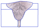 [117] |
| Low-carbon X8Ni9 steel 9 mm | Square edge, 0 gaps | CO2 laser (leading) + GMAW 55 mm (tandem) | 1150 kJ/m | 127,778 kJ/m2 | 0.28 | 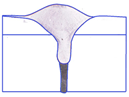 [117] |
Disclaimer/Publisher’s Note: The statements, opinions and data contained in all publications are solely those of the individual author(s) and contributor(s) and not of MDPI and/or the editor(s). MDPI and/or the editor(s) disclaim responsibility for any injury to people or property resulting from any ideas, methods, instructions or products referred to in the content. |
© 2025 by the authors. Licensee MDPI, Basel, Switzerland. This article is an open access article distributed under the terms and conditions of the Creative Commons Attribution (CC BY) license (https://creativecommons.org/licenses/by/4.0/).
Share and Cite
Costanza, G.; Giudice, F.; Missori, S.; Scolaro, C.; Sili, A.; Tata, M.E. An Overview of the Working Conditions of Laser–Arc Hybrid Processes and Their Effects on Steel Plate Welding. J. Manuf. Mater. Process. 2025, 9, 248. https://doi.org/10.3390/jmmp9080248
Costanza G, Giudice F, Missori S, Scolaro C, Sili A, Tata ME. An Overview of the Working Conditions of Laser–Arc Hybrid Processes and Their Effects on Steel Plate Welding. Journal of Manufacturing and Materials Processing. 2025; 9(8):248. https://doi.org/10.3390/jmmp9080248
Chicago/Turabian StyleCostanza, Girolamo, Fabio Giudice, Severino Missori, Cristina Scolaro, Andrea Sili, and Maria Elisa Tata. 2025. "An Overview of the Working Conditions of Laser–Arc Hybrid Processes and Their Effects on Steel Plate Welding" Journal of Manufacturing and Materials Processing 9, no. 8: 248. https://doi.org/10.3390/jmmp9080248
APA StyleCostanza, G., Giudice, F., Missori, S., Scolaro, C., Sili, A., & Tata, M. E. (2025). An Overview of the Working Conditions of Laser–Arc Hybrid Processes and Their Effects on Steel Plate Welding. Journal of Manufacturing and Materials Processing, 9(8), 248. https://doi.org/10.3390/jmmp9080248