1. Introduction
Forging is a widely used metal-forming process in the automotive, aerospace, and heavy engineering industries [
1], due to its reliability and cost-effectiveness in producing high-performance parts such as crankshafts, turbine blades, and connecting rods [
2]. As manufacturing priorities shift toward sustainability, there is growing interest in processes that reduce material waste, energy consumption, and tooling wear [
3].
Near-solidus forging (NSF), a hot forming method carried out close to the solidus temperature of metals, offers such benefits [
4]. It enables the production of complex geometries at lower forging loads and often eliminates the need for multiple forming steps [
5]. Recent studies highlight the significant advantages of near-solidus forging (NSF) in reducing forming forces and enabling industrial-scale production of complex steel components. Slater et al. [
6] demonstrated successful co-forging of a dual-material spindle using a single 280-ton press, confirming process feasibility at near-solidus temperatures. Lozares et al. [
7] validated the thixoformability and mechanical performance of 42CrMo4E steel in forging an automotive spindle. Meanwhile, Plata et al. [
8] reviewed key developments in NSF, underscoring its industrial readiness and environmental benefits. For instance, Sajjad et al. [
9] developed a digital twin model for NSF of 42CrMo4 steel, emphasizing the role of friction modeling, while Sánchez et al. [
10] showed how heating rates affect the resulting microstructure.
Despite its advantages, NSF presents significant challenges, particularly related to die durability and process control [
11]. The combination of high temperatures (1200–1500 °C), rapid tool-part interaction, and intense contact pressures leads to various forms of tool damage [
12]. Lateral forces account for up to 72% of tool wear, especially near radii and contact zones [
13]. Additional damage mechanisms include mechanical cracking (25%), thermal fatigue (2%), and plastic deformation (1%) [
14]. These issues can also cause die opening and misalignment, which compromise dimensional accuracy and reduce die life.
Addressing these challenges requires careful attention to die design, especially in terms of the gating system geometry, draft angles, and part orientation, which strongly affect how material flows and how loads are transmitted during the process [
15]. While FEM-based simulations have been applied to analyze stress and deformation during hot forging, few studies have examined how die geometry influences lateral forces and tooling conditions in the context of NSF.
Gating system design has been studied in casting, where factors like ingate geometry, runner cross-section, and gate placement influence flow behavior, defect formation, and process efficiency [
16]. Tools such as computer-aided design systems and modeling techniques have helped optimize these parameters to reduce defects and improve outcomes [
17]. These principles are equally relevant to near-solidus forging (NSF), where controlled flow is essential under semisolid conditions. However, these principles have not yet been explored or applied in NSF. This study adapts casting-derived design strategies for use in NSF, evaluating how they influence material behavior, cavity filling, and mechanical loading.
Using Forge NxT, this study numerically investigates the effects of gating geometry (conical, cylindrical, and curvilinear), draft angles (20° and 30°), and part orientation on punch force, lateral force, and thermomechanical behavior during NSF of a T-shaped steel component. This geometry was chosen for its complexity and sensitivity to unbalanced flow, making it ideal for assessing the effectiveness of die design variations. The results provide insight into how die geometry can be tailored to reduce forming loads, limit tooling damage, and improve process stability in industrial NSF applications.
2. Materials and Methods
The selected material for the modeling and simulation of the near-solidus forging (NSF) process, as well as the configuration of the kinematics and other simulation parameters, are described in this section as follows.
2.1. Material Selection and Properties
The material used in this study is 42CrMo4E steel, provided by Gerdau I+D Europe (Basauri, Spain) [
7], chosen for its high strength, good ductility, and suitability for high-temperature forming operations. This steel is commonly used in industrial forging processes where strength and thermal stability are required. Its chemical composition is presented in
Table 1. The material behavior at elevated temperatures was modeled using the Hensel–Spittel constitutive Equation (
1), with parameters calibrated and validated through prior experimental work by [
18].
where
is the flow stress (MPa),
T is the temperature (°C),
is the equivalent strain,
is the strain rate (s
−1), and
A,
,
,
, and
are material-specific constants.
The parameters used for the Hensel–Spittel model are summarized in
Table 2.
2.2. Finite Element Modelling and Simulation
A three-dimensional (3D) model was developed to simulate the NSF of steel billets. In the simulation setup, the billet was modeled as a deformable body, while the dies and punch were set as rigid bodies.
2.2.1. Geometry Modelling
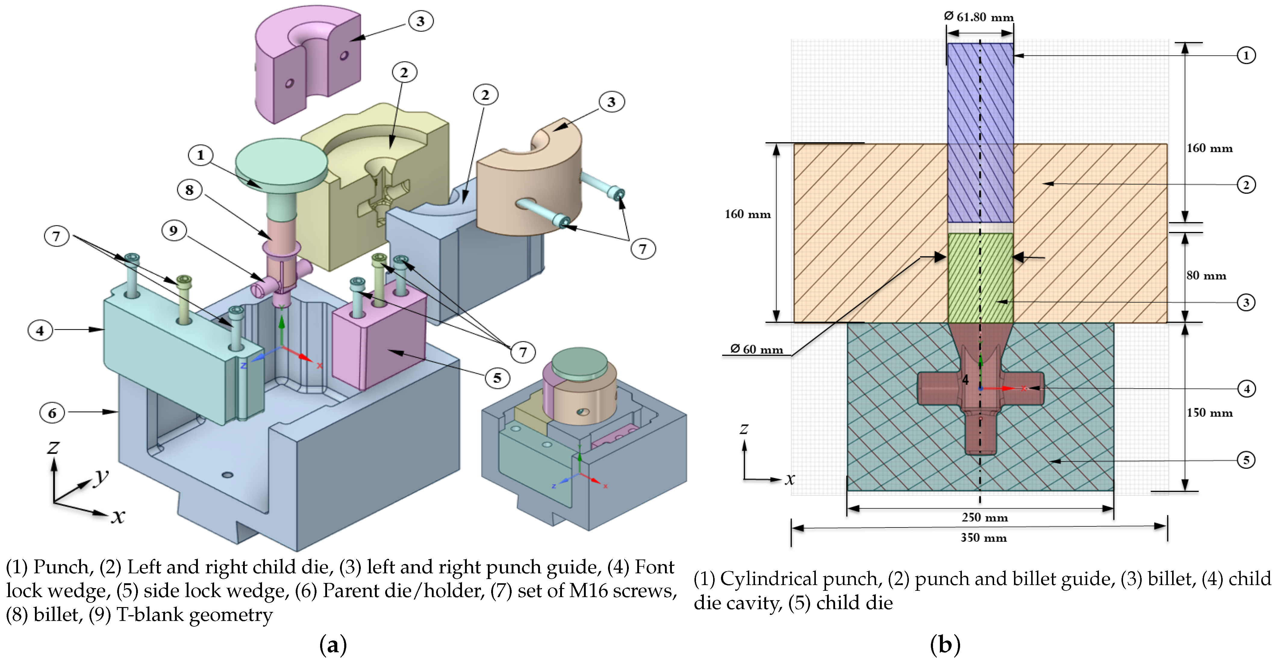
Figure 1 illustrates the billet, punch, and die setup. The billet was a cylinder (Ø60 mm × 40 mm), while the punch was a flat-bottomed cylinder (Ø61.80 mm × 160 mm) designed to apply uniform pressure. The die assembly comprised two symmetrical child dies forming a closed cavity tailored for complete filling under near-solidus conditions, with draft angles included for easy demolding.
2.2.2. Design Variations
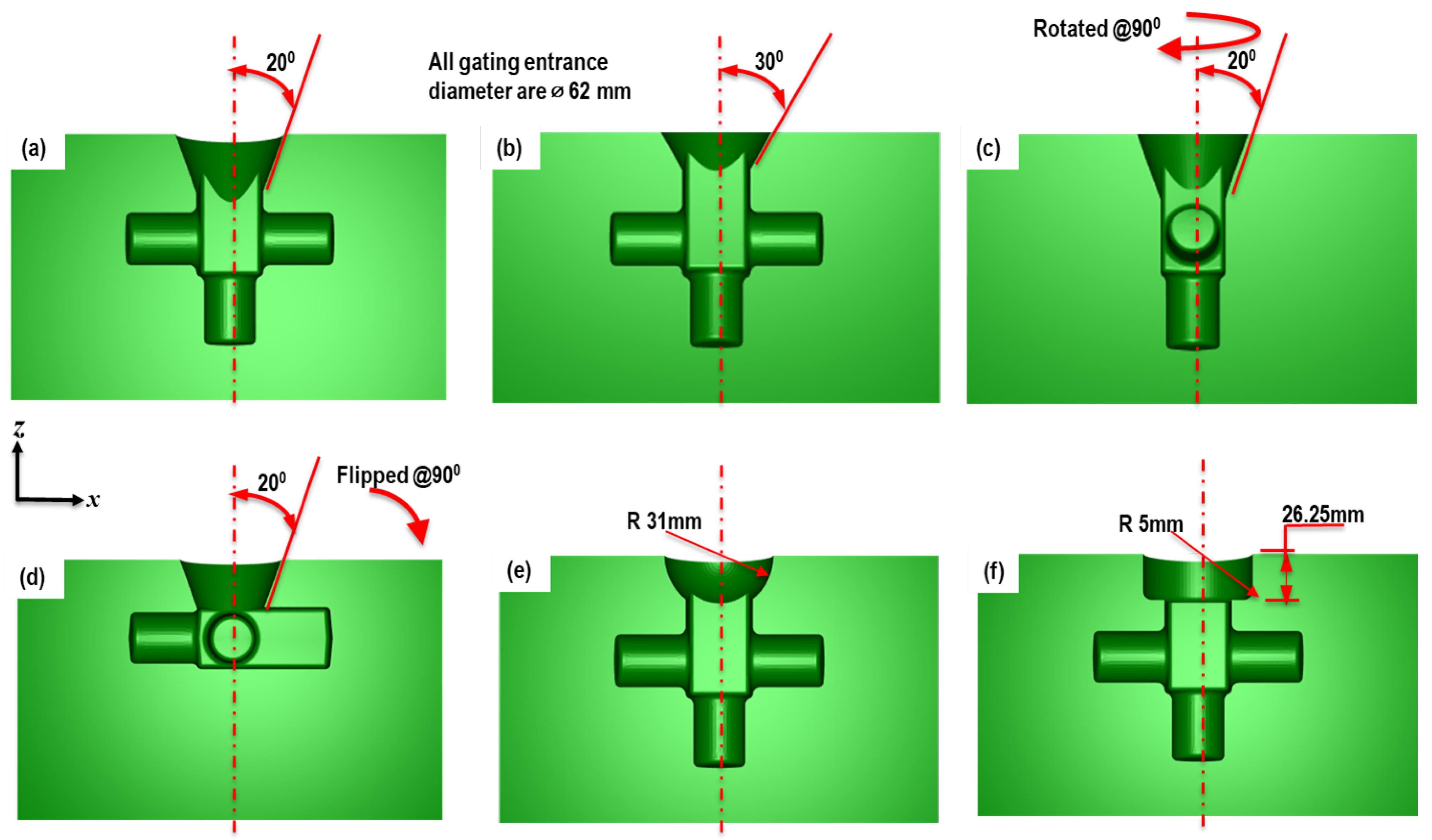
To investigate the influence of die configuration on forming behavior in near-solidus forging (NSF), six simulation cases (cases a, b, c, d, e, and f) were developed by systematically varying three critical design parameters: geometry positioning, gating system type, and draft angle. These variations are aimed at understanding their effects on forming forces (particularly punch and lateral forces), material flow behavior, and die stress.
Each design modification was selected based on prior studies and engineering judgment to address specific process limitations such as high die stress, non-uniform filling, and excessive flash formation. The full set of design variations and their configurations are shown in
Figure 2, and details are summarized in
Table 3.
Geometry positioning was modified to assess the impact of part placement oriented normal (vertical) to the punch force versus perpendicular (horizontal) to the press force on material symmetry and lateral load distribution.
Gating system types (conical, cylindrical, and curvilinear) were tested to determine which entry path promotes smoother material flow and reduces pressure buildup.
Draft angles (20° and 30°) were chosen based on manufacturability constraints and their known influence on die filling and ejection.
2.2.3. Mesh
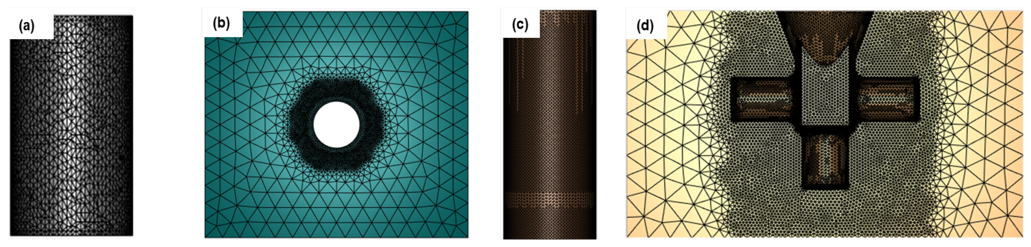
The child die and punch were modeled as rigid bodies and discretized with a coarser mesh, sufficient to describe their geometry without unnecessary computational cost. The billet and the punch were both assigned an initial global mesh size of 2 mm, while the punch guide and the child dies were meshed with element sizes in
Table 4. An illustration of the meshed components is shown in
Figure 3, highlighting the mesh density distribution applied to each tool and the billet.
In regions of interest, particularly near the billet-die interfaces and sharp corners of the die cavity, local mesh refinement was applied automatically by the software to improve solution accuracy.
2.2.4. Thermo-Mechanical Properties of the Material
The billet material, 42CrMo4E steel, was modeled using the Hensel-Spittel constitutive law as previously defined in
Section 2.1. The calibrated parameters were implemented into the simulation to accurately represent material behavior under high-temperature deformation. Thermal and mechanical properties such as thermal conductivity, specific heat, density, and Young’s modulus were assigned based on literature values and are summarized in
Table 5.
The dies and punch were modeled as rigid bodies with elastic behavior, neglecting thermal expansion to reduce computational cost. Heat transfer between the billet, dies, and surrounding environment was considered through specified thermal contact and convection coefficients.
2.2.5. Press Kinematics
The forging was modeled using a single-acting vertical press, where only the upper die (punch) was allowed to move. A constant downward velocity of 200 mm/s was applied in the negative Y-direction until full cavity filling. All other dies were fixed to replicate industrial die constraints. The punch displacement was used to track forming stages and monitor press force evolution.
2.2.6. Initial Conditions
The billet was assigned an initial temperature of 1360 °C according to [
7,
19], which corresponds to the near solidus range of 42CrMo4E steel, allowing partial solid deformation during forging. The dies and punch were assumed to be at a constant initial temperature of 50 °C, representing typical tool preheating conditions to reduce thermal shock and premature wear. No initial stresses or strains were applied to the billet or tooling. The simulation assumes thermal equilibrium at the start of deformation, and no preloading or residual stress conditions were included.
2.2.7. Boundary Conditions
The mechanical press movement was simulated using a velocity vs. height control mode with a constant press speed of 200 mm/s. The heat transfer coefficient was obtained from the Forge database [
20], and friction conditions were obtained from the previous work by [
21]. The key boundary parameters applied in the simulation are summarized in
Table 6.
3. Model Validation
The reliability of the numerical model was assessed by comparing simulation results with experimental data from Plata et al. (2018) [
23], which involved the near-solidus forging of an automotive spindle shown in
Figure 4a.
3.1. Geometry and Process Description
The displacement–time profile used in the simulation was extracted from the experimental study (
Figure 4b in [
23]). This profile was applied as a kinematic input to drive the punch movement. Other conditions, such as initial temperature, die temperature, and frictional contact definitions, were matched to those reported experimentally to ensure a consistent thermomechanical environment.
3.2. Force-Time Comparison for the Experimental and Numerical Model
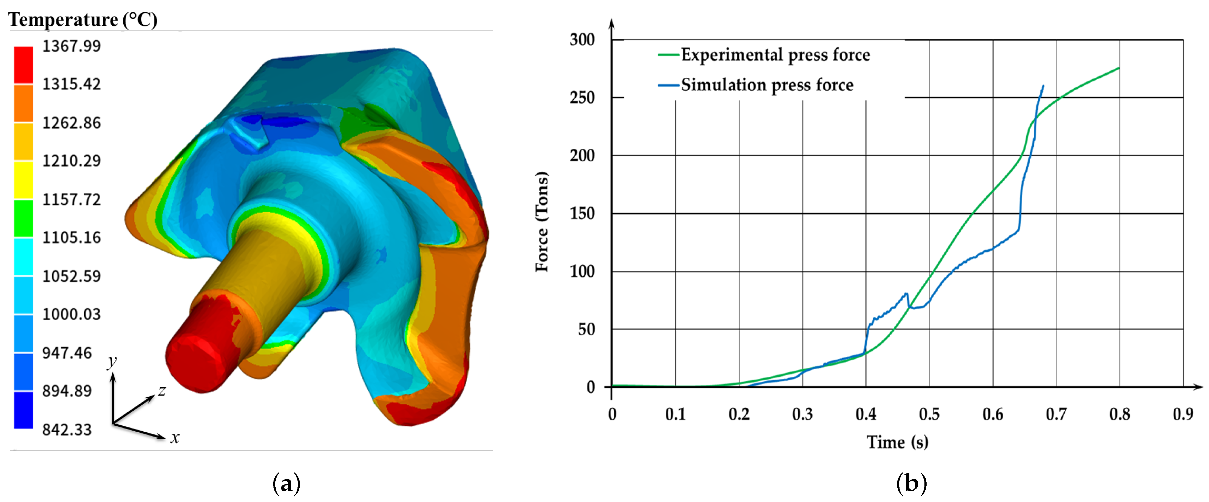
The simulation output was evaluated in terms of punch force and forming time. The predicted maximum punch force was 271.14 tons, which occurred at 0.72 s, closely matching the experimental results of 275.28 tons at 0.79 s as presented in
Table 7. This corresponds to a 1.5% force deviation and an 8.9% time deviation, which are considered acceptable in forging simulations given the inherent approximations in material behavior and heat transfer modeling.
The discrepancy in time is attributed to factors such as simplified friction conditions, assumptions of perfect heat transfer, and material property idealizations in the simulation model. However, the general shape and trend of the force curve are consistent, indicating that the model captures the primary mechanical behavior of the process. The result of the temperature profile of the spindle after complete filling and the comparison of the punch force from the simulation with the experimental press force are presented in
Figure 5.
4. Results
The results of the finite element simulations for the different die design variant cases (a–f) presented in
Table 3 are summarized in terms of maximum press force and peak lateral force acting on the child dies. These force values were extracted at the moment of complete cavity filling for each case.
4.1. Press and Lateral Force Analysis
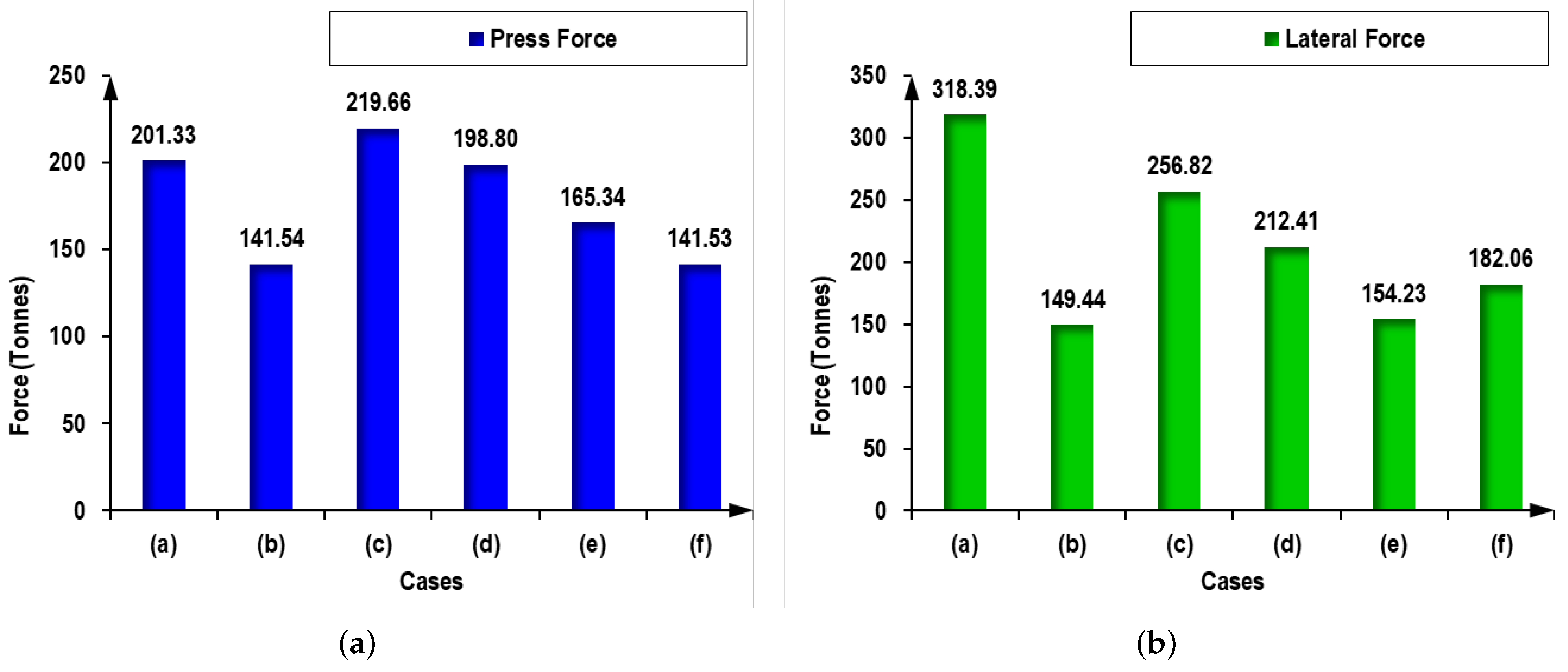
Figure 6 presents a comparative bar chart of the punch force and lateral force exerted on the child dies for each design case in the near-solidus forging (NSF) process. The punch force reflects the load required to fully fill the cavity, while the lateral force corresponds to the reactive stress transmitted to the die walls. Excessive lateral force can induce die opening, misalignment, or premature wear. This graphical comparison enables a clearer evaluation of which design variants reduce forming load and minimize die stress, which are critical for process efficiency and tool durability.
Figure 6 shows the effect of design variations on punch force and lateral force on child dies required for complete cavity filling. Cases a–f explore the effects of geometry positioning, gating system type, and draft angle. The 30° cone design case b and curvilinear entry case e showed significant reductions in both press and lateral forces, while rotated and flipped geometries cases c and d increased the load response, indicating less efficient force transmission and higher lateral stress on the dies.
To streamline further analysis and avoid redundancy, a discriminatory selection was made based on the combined behavior of press force and lateral force. Cases c and d were excluded due to their relatively higher lateral or press forces, which may lead to increased die stress, energy consumption, or poor forming efficiency. The remaining cases b, e, and f exhibited favorable balances between forming load and die reaction forces, making them more suitable for optimized forming. These three were therefore selected for detailed thermo-mechanical analysis in the next section.
4.2. Thermomechanical Analysis of the Selected Cases
This section presents the contour plots of temperature, equivalent strain, and strain rate to evaluate material flow, cavity filling, and potential recrystallization behavior. Only cases a, b, e, and f were retained for this analysis.
4.2.1. Temperature Distribution Profile
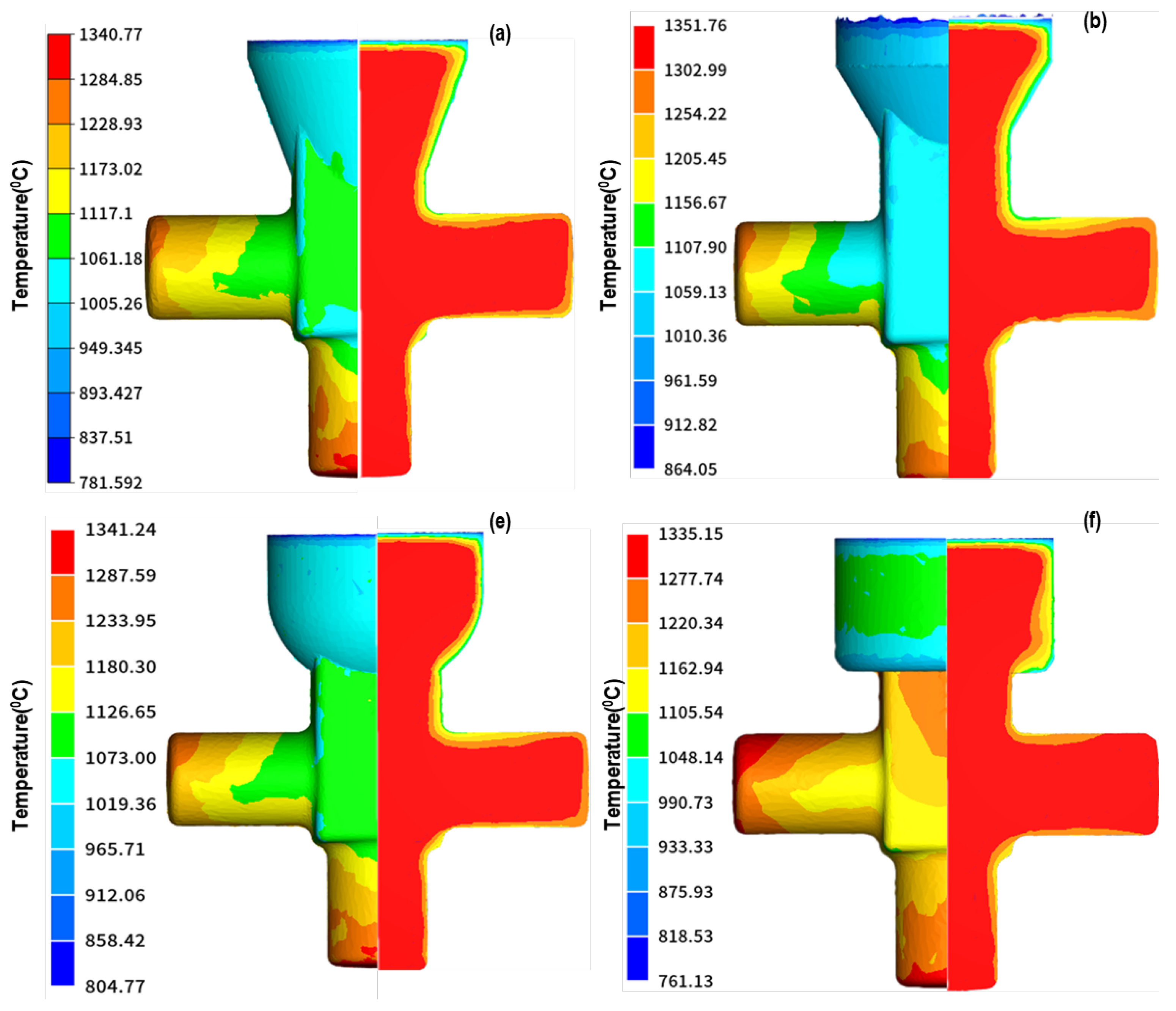
Figure 7 presents the temperature distribution profiles for the four selected cases (a, b, e, and f). Each subfigure displays two views: the left-hand side shows the surface temperature of the forged part, while the right-hand side presents a cross-sectional view that reveals the temperature distribution within the internal core of the geometry.
The overall distribution is similar across all cases, but differences in minimum temperatures reveal distinct heat retention behavior. Case (b) exhibited the most favorable thermal retention, with a minimum of 864.05 °C, followed by case (e) at 804.77 °C and case (a) at 781.59 °C, while case (f) demonstrated the least favorable thermal performance with the lowest minimum temperature of 761.13 °C, indicating higher heat loss during forming.
4.2.2. 3D Equivalent Strain Profile
Figure 8 presents the equivalent strain distribution profiles for the selected cases (a, b, e, and f). Each subfigure consists of two views: the left-hand side displays the surface strain distribution of the forged component, and the right-hand side shows a cross-sectional view highlighting the internal strain distribution. Case (f) exhibits the highest peak strain, 12.47, indicating more intense localized deformation. Case b also shows significant strain accumulation (7.82), while cases a and c display lower and more uniformly distributed strain levels across the geometry.
4.2.3. 3D Strain Rate Profile
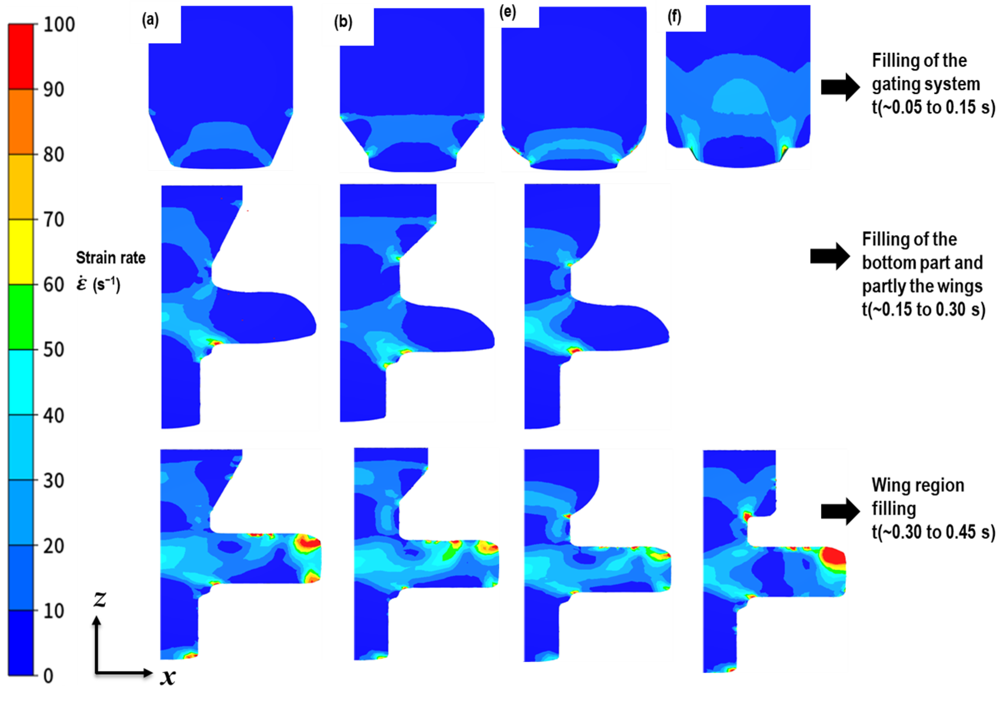
Figure 9 illustrates the strain rate distribution for the selected designs at representative time steps during the cavity filling process. The analysis focuses on three key stages observed across all cases (a, b, e, and f), with time points selected based on the moment each case reached specific filling milestones:
Stage I (Initial filling∼0.05 to 0.15 s): A sharp rise in strain rate is observed at the transition between the vertical and horizontal walls, particularly as the material enters the gating system. This effect is most pronounced in case (f), due to the radius of the cylindrical gating of the child die.
Stage II (Wing region filling∼0.15 to 0.30 s): A notable increase in strain rate occurs as the material spreads into the lateral wing areas of the cavity.
Stage III (Full cavity filling∼0.30 to 0.45 s): The strain rate intensifies again at the cavity corners and near sharp features, where the material flow decelerates and is redirected. Localized peaks are evident in all cases, though cases (b) and (e) show a smoother distribution due to more balanced flow paths.
All cases display a similar overall distribution pattern, with average strain rates ranging from 20–50 s−1. However, cases (b) and (e) demonstrated smoother flow behavior and more uniform strain rate distribution compared to cases (a) and (f), indicating better material deformation and die-filling characteristics.
5. Discussion
This section discusses the influence of die design variations on the near-solidus forging (NSF) process based on the selected cases: (a) base design, (b) cone gating with 30° draft, (e) curvilinear gating, and (f) cylindrical gating. Cases (c) and (d) were excluded due to excessive forming forces and prolonged cavity filling times. Forming forces, particularly press and lateral forces, are crucial for evaluating die stress and forming efficiency. Case (a) exhibited the highest lateral force (318.39 t), indicating significant resistance to material flow and increased risk of die wear or failure. Case (b) showed the most favorable response, with the lowest lateral force (149.44 t) and press force (141.54 t), suggesting efficient material feeding with minimal expansion of the die cavity. Case (e) offered a balanced force response, while case (f), despite its low lateral force, showed signs of flow irregularity, raising concerns about final part integrity.
Temperature distribution plays a vital role in maintaining material deformability in NSF. Case (b) retained the most favorable temperature profile, with a high and uniform distribution ranging from 864.05 to 1351.76 °C, which promotes steady plastic flow. Case (e) also exhibited good thermal retention. In contrast, Case f experienced the lowest minimum temperature (761.13 °C), which may result in restricted flow during the final filling stages. Case (a) presented moderate thermal behavior but with uneven distribution.
Equivalent strain analysis reflects the degree and uniformity of deformation across the part. Case (b) showed a maximum strain of 7.82, with a uniform distribution that supports consistent mechanical properties. Case (f) reached the highest strain value (12.47), particularly concentrated near cavity corners, indicating localized over-deformation that may lead to tool damage or material defects. Cases (a) and (e) demonstrated moderate strain levels, with case (e) offering better deformation uniformity due to its smooth curvilinear profile.
Strain rate behavior followed a three-stage evolution: initial flow through the gating system, expansion into the wing regions, and final filling of the cavity corners. Across all cases, average strain rates ranged between 20 and 50−1. Case (b) provided the smoothest transition between stages, minimizing abrupt changes that could cause stress accumulation. Case (e) also showed stable progression. Conversely, case (f) exhibited concentrated strain rate peaks at cavity corners, indicating irregular filling behavior despite low force demands. Case (a) presented a typical transition but with less control over material flow.
In summary, case (b) proved to be the most effective configuration, achieving low forming resistance, stable thermal and mechanical behavior, and smooth material flow, which collectively enhance die life and part quality. Case (e) is also a promising alternative due to its consistent strain and temperature profiles. Cases (a) and (f) were less favorable overall, reinforcing the importance of optimizing gating geometry for successful NSF applications.
6. Conclusions
This study analyzed the influence of die design parameters on the forging response of complex steel geometries under NSF conditions. Using finite element simulations in Forge NxT, six die configurations were evaluated, varying geometry orientation, gating system shape, and draft angles. The goal was to understand how these design modifications affect punch force, lateral force, material flow, and thermomechanical behavior. Cases c and d, which involved rotating the base geometry by 90°, were excluded due to poor material filling and excessively high lateral loads that could compromise die integrity and part quality. The analysis therefore focused on four configurations: a base geometry (a) with a 20° draft angle, (b) a conical gating system with a 30° draft angle, (e) a curvilinear gating system, and (f) a cylindrical gating system. The simulation results led to the following key conclusions:
Case b, featuring a conical gating system with a 30° draft angle, delivered the best overall performance with the lowest punch 141.54 t and lateral forces 149.44 t, a uniform temperature distribution (864.05–1351.76 °C), and a maximum equivalent strain of 7.82, indicating efficient deformation and lower risk of die damage.
Case e curvilinear design also showed promising thermomechanical behavior, providing smoother material flow and better strain distribution compared to the base and cylindrical designs, although it generated slightly higher lateral forces than Case b.
Case f cylindrical gating resulted in localized over-deformation, reaching a peak strain of 12.47, which could lead to internal defects and reduced part integrity.
The base design, case (a), exhibited the highest lateral force, 318.39 t, and uneven strain distribution, suggesting high stress concentrations in the die and reduced product quality.
These findings highlight the importance of optimizing gating geometry and draft angles to minimize tooling loads, improve material distribution, and enhance the quality and reliability of forged components under NSF conditions.
Author Contributions
Conceptualization, J.D.S. and A.M.-M.; methodology, J.D.S. and A.M.-M.; software, J.D.S.; validation, J.D.S., A.M.-M., E.G. and C.S.; formal analysis, J.D.S. and A.M.-M.; investigation, J.D.S.; resources, J.D.S.; data curation, J.D.S.; writing—original draft preparation, J.D.S.; writing—review and editing, J.D.S., A.M.-M. and E.G.; visualization, J.D.S.; supervision, A.M.-M., E.G. and C.S.; project administration, A.M.-M.; funding acquisition, A.M.-M. and C.S. All authors have read and agreed to the published version of the manuscript.
Funding
This study received financial support from the Department of Education of the Basque Government for the Research Group program IT1507-22 and and from the Carbon Trust, through the initiative Net Zero Innovation Portfolio.
Data Availability Statement
The data presented in this study are available on request from the corresponding author.
Conflicts of Interest
The authors declare no conflicts of interest. The funders had no role in the design of the study; in the collection, analyses, or interpretation of data; in the writing of the manuscript; or in the decision to publish the results.
Abbreviations
The following abbreviations are used in this manuscript:
| NSF | Near-Solidus Forming |
| CAD | Computer-Aided Design |
| FEM | Finite Element Method |
| 3D | Three Dimensional |
References
- Kocańda, A.; Czyżewski, P.; Mehdi, K.H. Numerical analysis of lateral forces in a die for turbine blade forging. Arch. Civ. Mech. Eng. 2009, 9, 49–54. [Google Scholar] [CrossRef]
- Torabi, S.; Alibabaei, S.; Bonab, B.B.; Sadeghi, M.; Faraji, G. Design and optimization of turbine blade preform forging using RSM and NSGA II. J. Intell. Manuf. 2017, 28, 1409–1419. [Google Scholar] [CrossRef]
- Uddin, M.S.; Kumar, S. Energy, emissions and environmental impact analysis of wind turbine using life cycle assessment technique. J. Clean. Prod. 2014, 69, 153–164. [Google Scholar] [CrossRef]
- Plata, G.; Lozares, J.; Sánchez, A.; Hurtado, I.; Slater, C. Preliminary study on the capability of the novel near solidus forming (NSF) technology to manufacture complex steel components. Materials 2020, 13, 4682. [Google Scholar] [CrossRef] [PubMed]
- Lozares, J.; Plata, G.; Hurtado, I.; Sánchez, A.; Loizaga, I. Near solidus forming (NSF): Semi-solid steel forming at high solid content to obtain as-forged properties. Metals 2020, 10, 198. [Google Scholar] [CrossRef]
- Slater, C.; Plata, G.; Sánchez, A.; Lozares, J.; Hurtado, I. A novel forming technique to coforge bimetal components into complex geometries. Manuf. Lett. 2020, 26, 21–24. [Google Scholar] [CrossRef]
- Lozares, J.; Plata, G.; Azpilgain, Z.; Álvarez, G. Semisolid Forming of 42CrMo4E Steel Grade. AIP Conf. Proc. 2016, 1769, 030006. [Google Scholar] [CrossRef]
- Plata, G.; Lozares, J.; Hurtado, I.; Azpilgain, Z. Semisolid Forging of Steels: Readiness from an Industrial Point of View. AIP Conf. Proc. 2019, 2113, 140001. [Google Scholar] [CrossRef]
- Sajjad, M.; Trinidad, J.; Plata, G.; Lozares, J.; Mendiguren, J. Sensitivity analysis of near solidus forming (NSF) process with digital twin using Taguchi approach. Adv. Manuf. 2024, 13, 322–336. [Google Scholar] [CrossRef]
- Sánchez-Fernández, A. Microstructural Evolution Analysis During the Near Solidus Forming Process: The Case of AISI 316. Ph.D. Thesis, Mondragon Unibertsitatea, Goi Eskola Politeknikoa, Arrasate, Spain, 2023. [Google Scholar] [CrossRef]
- Sajjad, M.; Agirre, J.; Plata, G.; Lozares, J.; Mendiguren, J. The influence of the adiabatic heating coefficient on the near solidus forming process. Int. J. Mater. Form. 2025, 18, 3. [Google Scholar] [CrossRef]
- Kopas, P.; Sága, M.; Novỳ, F.; Paulec, M. Influence of re-profiling on the premature failure of hot forging dies. Eng. Fail. Anal. 2023, 152, 107507. [Google Scholar] [CrossRef]
- Alimirzaloo, V.; Biglari, F.R.; Sadeghi, M.H.; Keshtiban, P.M.; Sehat, H.R. A novel method for preform die design in forging process of an airfoil blade based on Lagrange interpolation and meta-heuristic algorithm. Int. J. Adv. Manuf. Technol. 2019, 102, 4031–4045. [Google Scholar] [CrossRef]
- Emamverdian, A.A.; Sun, Y.; Cao, C.; Pruncu, C.; Wang, Y. Current failure mechanisms and treatment methods of hot forging tools (dies)—A review. Eng. Fail. Anal. 2021, 129, 105678. [Google Scholar] [CrossRef]
- Kocabıçak, A.C.; Wahab, M.A. Multiphysics numerical modelling of backward flow forming process of AISI 5140 steel. Simul. Model. Pract. Theory 2022, 121, 102656. [Google Scholar] [CrossRef]
- Kim, C.H.; Kwon, T.H. A runner–gate design system for die casting. Mater. Manuf. Processes 2001, 16, 789–801. [Google Scholar] [CrossRef]
- Tai, C.; Lin, J. A runner-optimization design study of a die-casting die. J. Mater. Process. Technol. 1998, 84, 1–12. [Google Scholar] [CrossRef]
- Bilbao, O.; Loizaga, I.; Alonso, J.; Girot, F.; Torregaray, A. 42CrMo4 steel flow behavior characterization for high temperature closed dies hot forging in automotive components applications. Heliyon 2023, 9, e22256. [Google Scholar] [CrossRef] [PubMed]
- Lozares, J.; Mendiguren, J.; Gorka, P.; Muhammad, S. Digital twin development for the sensitivity analysis of near solidus forming process. Mater. Res. Proc. 2023, 28, 1521–1530. [Google Scholar] [CrossRef]
- Transvalor, S.A. FORGE® NxT version 4.0: Simulation Software for Hot Forging Processes. 2025. Available online: https://www.transvalor.com/en/forge (accessed on 15 April 2023).
- Sajjad, M.; Agirre, J.; Plata, G.; Lozares, J.; Mendiguren, J. Characterization of friction coefficient at near solidus forming (NSF) conditions using T-shape compression test. J. Manuf. Process. 2024, 124, 1259–1272. [Google Scholar] [CrossRef]
- Pater, Z.; Tomczak, J.; Shu, X.; Li, Z. Innovative method of rolling railcar axles using segmented tool assemblies. Adv. Sci. Technol. Res. J. 2025, 19, 271–282. [Google Scholar] [CrossRef] [PubMed]
- Plata, G. Semi-Solid Forging of Steels: New Insights Into Material Behaviour Evolution and Industrialisation. PhD Thesis, University of Mondragon, Arrasate, Spain, 2018. [Google Scholar] [CrossRef]
Figure 1.
(a) NSF T-Blank Forging Assembly and (b) Base case configuration of the billet, punch, punch guide, and child dies setup in Forge NxT.
Figure 1.
(a) NSF T-Blank Forging Assembly and (b) Base case configuration of the billet, punch, punch guide, and child dies setup in Forge NxT.
Figure 2.
(a–f) Comparison of base case configuration and five other design variations. (a) Base case (b) Draft angle modified (c) Rotated geometry (d) Flipped geometry (e) Curvilinear gating (f) Cylindrical gating. The red arrows show the draft angles and the rotation of the part in the dies.
Figure 2.
(a–f) Comparison of base case configuration and five other design variations. (a) Base case (b) Draft angle modified (c) Rotated geometry (d) Flipped geometry (e) Curvilinear gating (f) Cylindrical gating. The red arrows show the draft angles and the rotation of the part in the dies.
Figure 3.
Mesh configurations: (a) billet, (b) punch guide, (c) punch, (d) child die.
Figure 3.
Mesh configurations: (a) billet, (b) punch guide, (c) punch, (d) child die.
Figure 4.
(
a) CAD model of the automotive R-spindle. (
b) Press force, ram position, and ram speed during the process [
23].
Figure 4.
(
a) CAD model of the automotive R-spindle. (
b) Press force, ram position, and ram speed during the process [
23].
Figure 5.
(a) Temperature profile of the R-spindle. (b) Experimental press force vs. numerical simulation press force.
Figure 5.
(a) Temperature profile of the R-spindle. (b) Experimental press force vs. numerical simulation press force.
Figure 6.
(a) Punch force comparison. (b) Lateral force on child dies comparison. Cases (a, b, c, d, e, and f) represent different die design configurations analyzed in the study.
Figure 6.
(a) Punch force comparison. (b) Lateral force on child dies comparison. Cases (a, b, c, d, e, and f) represent different die design configurations analyzed in the study.
Figure 7.
Temperature distribution profiles for selected cases (a,b,e,f). (a) Base case 20° draft angle (b) 30° Draft angle (e) Curvilinear gating (f) Cylindrical gating.
Figure 7.
Temperature distribution profiles for selected cases (a,b,e,f). (a) Base case 20° draft angle (b) 30° Draft angle (e) Curvilinear gating (f) Cylindrical gating.
Figure 8.
Equivalent strain profile of the selected cases (a,b,e,f). (a) Base case 20° draft angle (b) 30° Draft angle (e) Curvilinear gating (f) Cylindrical gating.
Figure 8.
Equivalent strain profile of the selected cases (a,b,e,f). (a) Base case 20° draft angle (b) 30° Draft angle (e) Curvilinear gating (f) Cylindrical gating.
Figure 9.
Sectional view of the strain rate profile of the selected cases (a,b,e,f). (a) Base case 20° draft angle (b) 30° Draft angle (e) Curvilinear gating (f) Cylindrical gating.
Figure 9.
Sectional view of the strain rate profile of the selected cases (a,b,e,f). (a) Base case 20° draft angle (b) 30° Draft angle (e) Curvilinear gating (f) Cylindrical gating.
Table 1.
Composition of the 42CrMo4E steel alloy in wt.% [
7].
Table 1.
Composition of the 42CrMo4E steel alloy in wt.% [
7].
| Elements | Fe | Cr | Mn | C | Mo | Si | P | S | Ni | V | Cu | Al |
|---|
| 42CrMo4E | Bal. | 1.06 | 0.76 | 0.42 | 0.20 | 0.30 | 0.02 | 0.02 | 0.20 | 0.01 | 0.03 | 0.02 |
Table 2.
Hensel–Spittel model parameters for 42CrMo4E steel.
Table 2.
Hensel–Spittel model parameters for 42CrMo4E steel.
| Parameters | A | | | | |
|---|
| Values | 23,921.66 | −0.0048 | 0.0120 | 0.0232 | −0.0267 |
Table 3.
Design parameters for each simulation case.
Table 3.
Design parameters for each simulation case.
| Case | Description | Geometry Position
Relative to Press Motion | Gating System | Draft Angle |
|---|
| a | Base case | Vertical | Cone | 20° |
| b | Draft angle modified | Vertical | Cone | 30° |
| c | Rotated geometry | Vertical | Cone | 20° |
| d | Flipped geometry | Horizontal | Cone | 20° |
| e | Gating system redesigned I | Vertical | Curvilinear | - |
| f | Gating system redesigned II | Vertical | Cylindrical | - |
Table 4.
Mesh sizes for the parts in Forge NxT.
Table 4.
Mesh sizes for the parts in Forge NxT.
| Average Mesh Size | Billet | Punch Guide | Punch | Child Die |
|---|
| Fine region (mm) | 2.00 | 2.00 | 2.00 | 2.00 |
| Coarse region (mm) | - | 22.82 | - | 13.82 |
Table 5.
Thermal and mechanical material properties, data from [
9,
12].
Table 5.
Thermal and mechanical material properties, data from [
9,
12].
| Property | Density
(kg/m3) | Specific Heat
(J/kg/K) | Thermal Conductivity
(W/m/K) | Young’s Modulus
(GPa) | Poisson’s
Ratio |
|---|
| Billet (42CrMo4E) | 7850.0 | 778.0 | 35.5 | 210.0 | 0.3 |
| Dies and punch (tool steel) | 7800.0 | 460.0 | - | 200.0 | 0.3 |
Table 6.
Summary of boundary conditions and process parameters [
21,
22].
Table 6.
Summary of boundary conditions and process parameters [
21,
22].
| Parameter | Value | Description |
|---|
| Press type | Mechanical | Velocity-controlled |
| Press speed | 200 mm/s | Constant throughout stroke |
| Friction model | Coulomb | Water + graphite lubrication |
| Friction coefficient () | 0.1500 | - |
| Shear friction factor (m) | 0.3000 | - |
| Heat transfer coefficient (die interface) | 10,000 W/m2·K | Billet–die contact |
| Heat transfer coefficient (air interface) | 10 W/m2·K | Billet–air contact |
| Tool effusivity (W.s1/2/m2·K) | 11,763.62 | Based on material thermal inertia |
Table 7.
Comparison of the experimental model with simulation parameters.
Table 7.
Comparison of the experimental model with simulation parameters.
| Parameter | Simulation | Experimental | Deviation |
|---|
| Max punch force (tons) | 271.14 | 275.28 | 1.5% |
| Forming time (s) | 0.72 | 0.79 | 8.9% |
| Disclaimer/Publisher’s Note: The statements, opinions and data contained in all publications are solely those of the individual author(s) and contributor(s) and not of MDPI and/or the editor(s). MDPI and/or the editor(s) disclaim responsibility for any injury to people or property resulting from any ideas, methods, instructions or products referred to in the content. |
© 2025 by the authors. Licensee MDPI, Basel, Switzerland. This article is an open access article distributed under the terms and conditions of the Creative Commons Attribution (CC BY) license (https://creativecommons.org/licenses/by/4.0/).


