
Experimental Investigations on Microstructure and Mechanical Properties of L-Shaped Structure Fabricated by WAAM Process of NiTi SMA


Abstract
1. Introduction
2. Materials and Methodology
2.1. Experimental Plan
2.2. Testing and Characterization
3. Results and Discussion
3.1. Fabrication of L-Structure
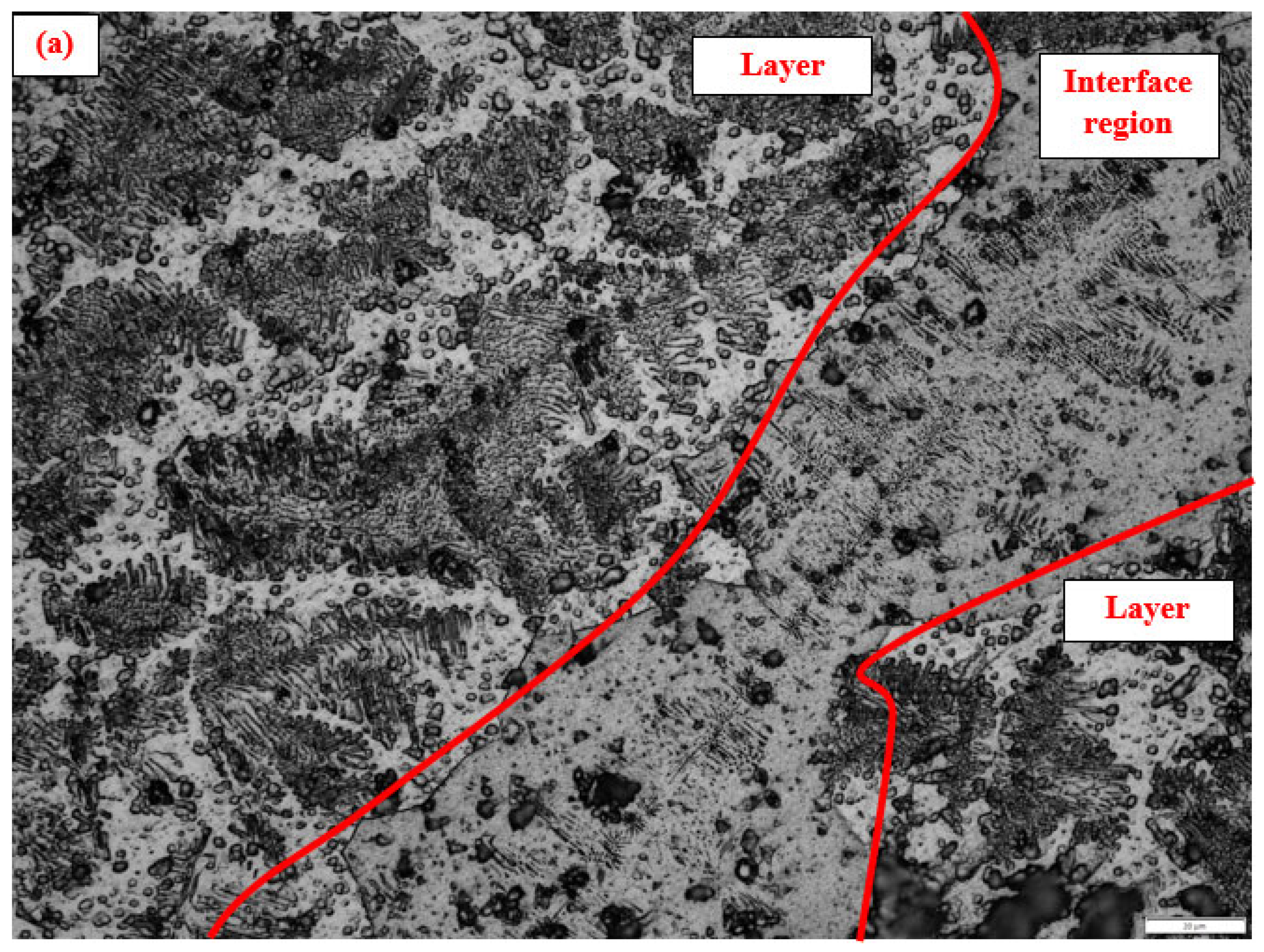
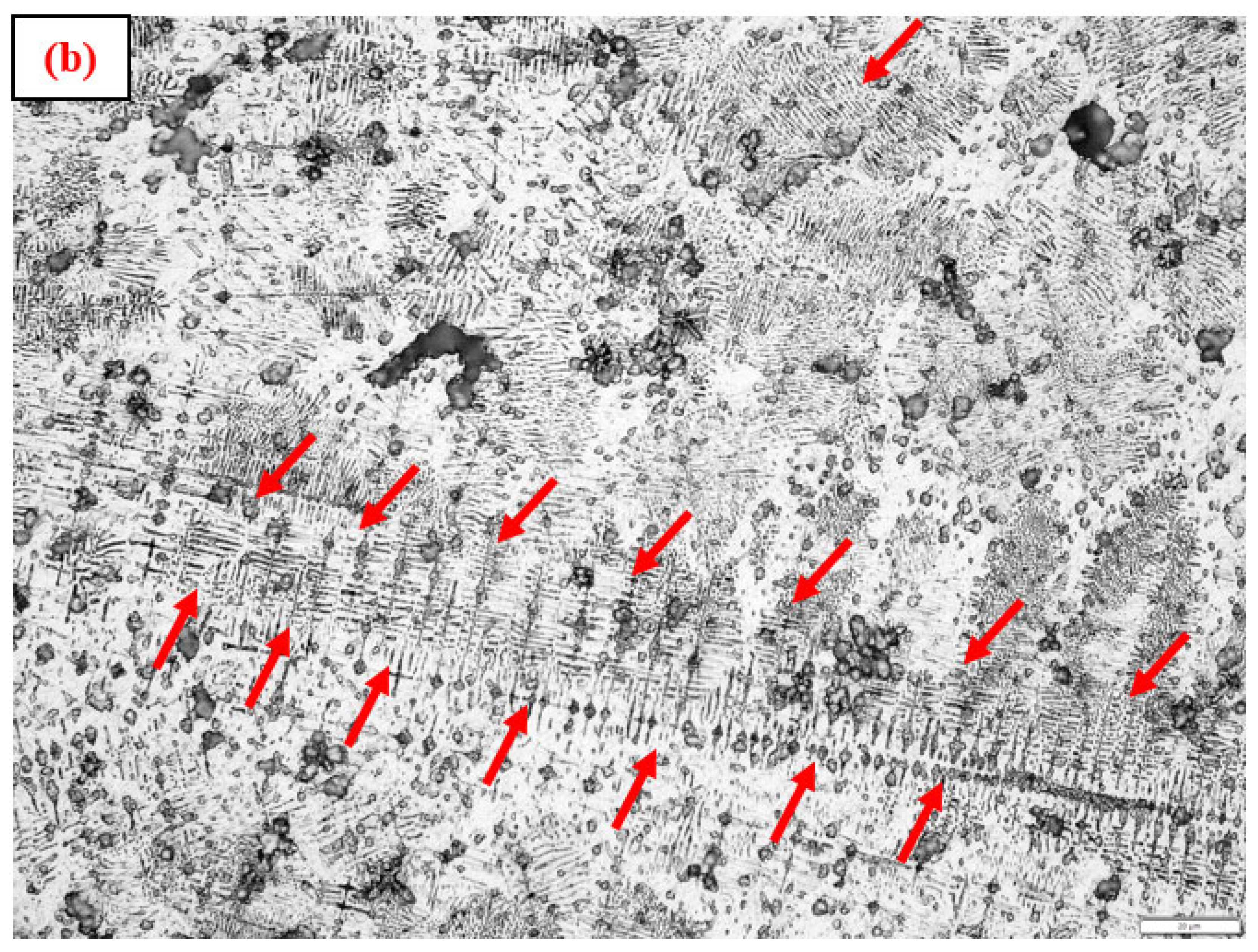
3.2. Macrostructure and Microstructure
3.3. Mechanical Characterizations
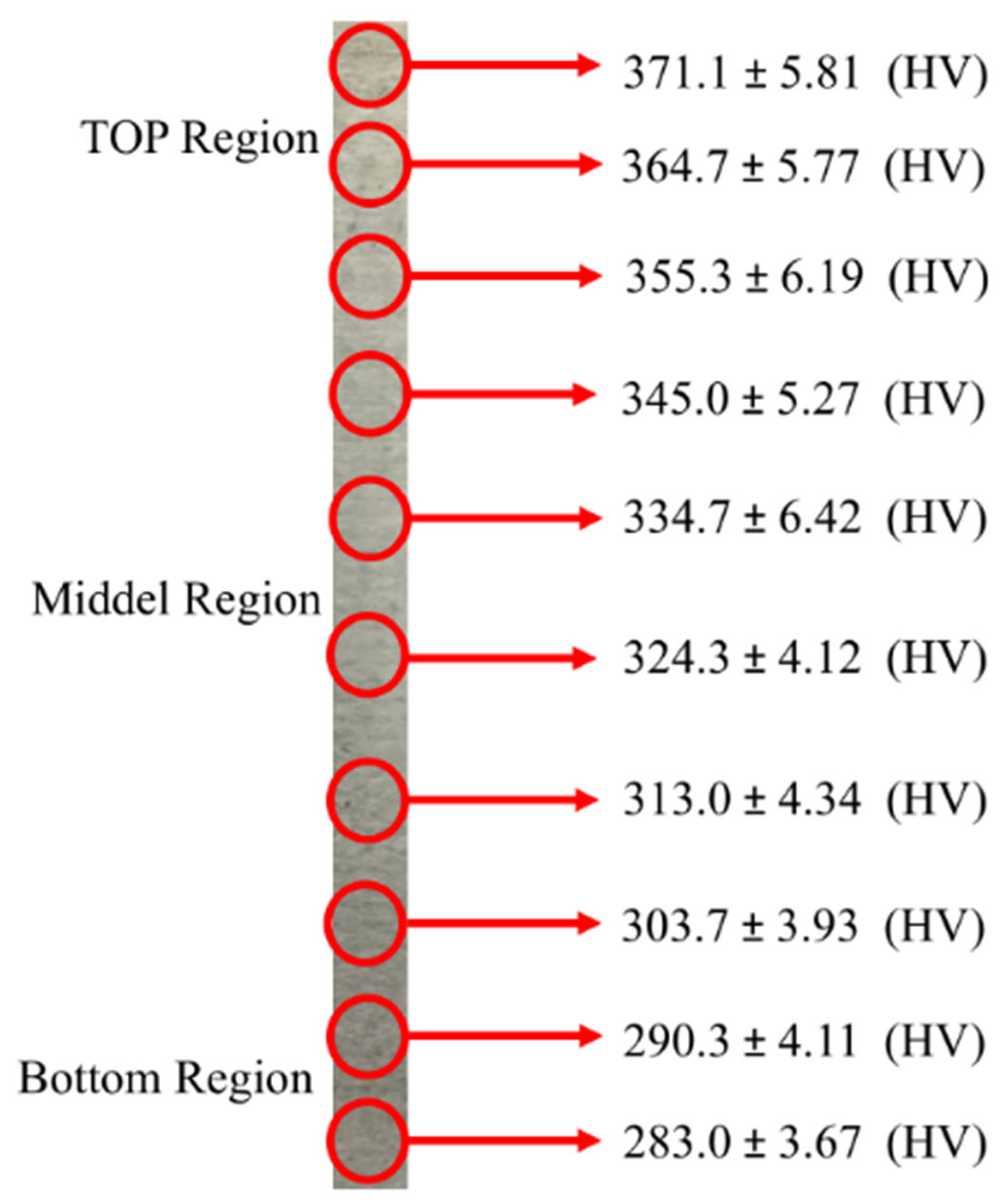
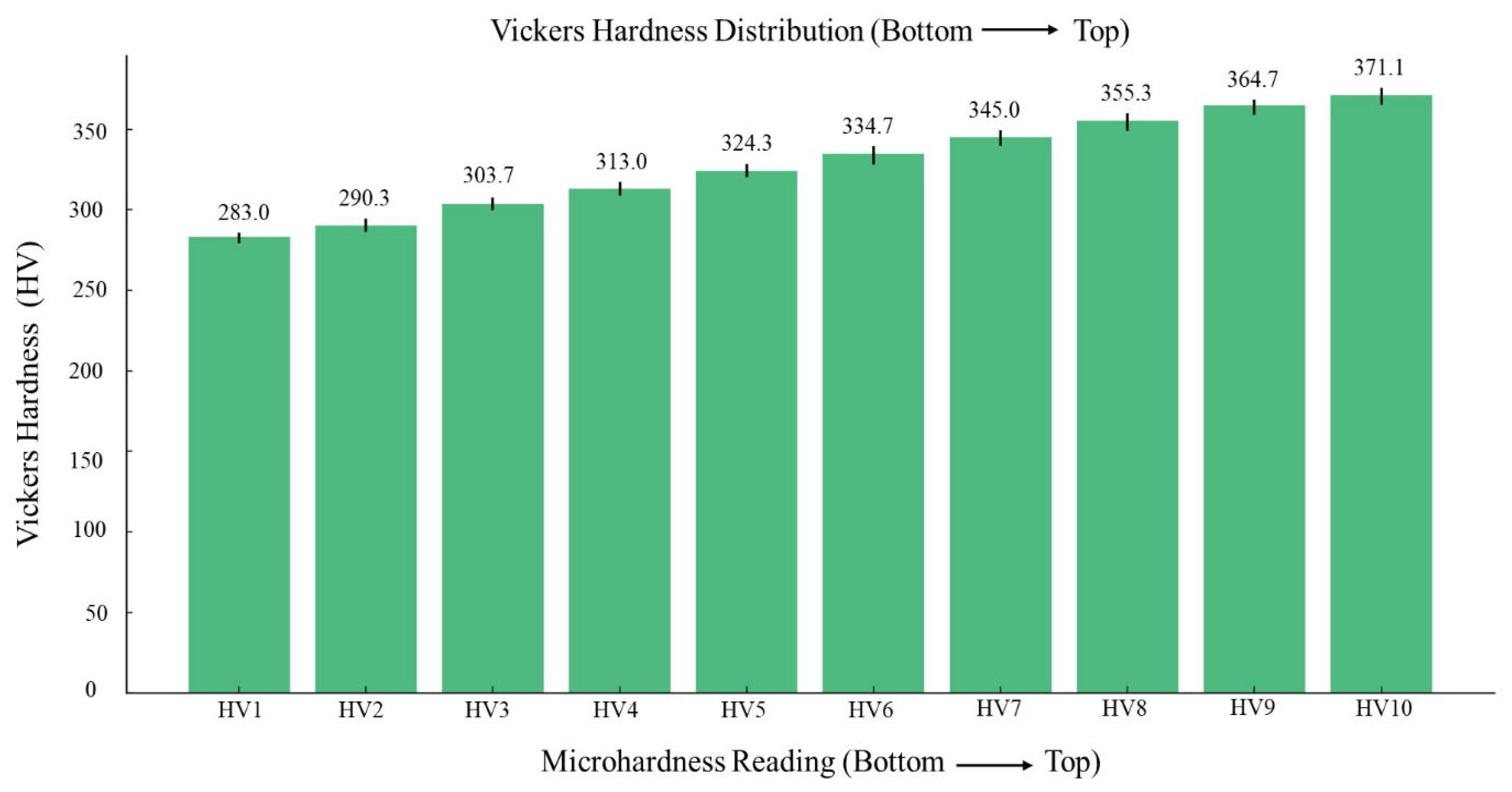
3.3.1. Microhardness
3.3.2. Tensile Test
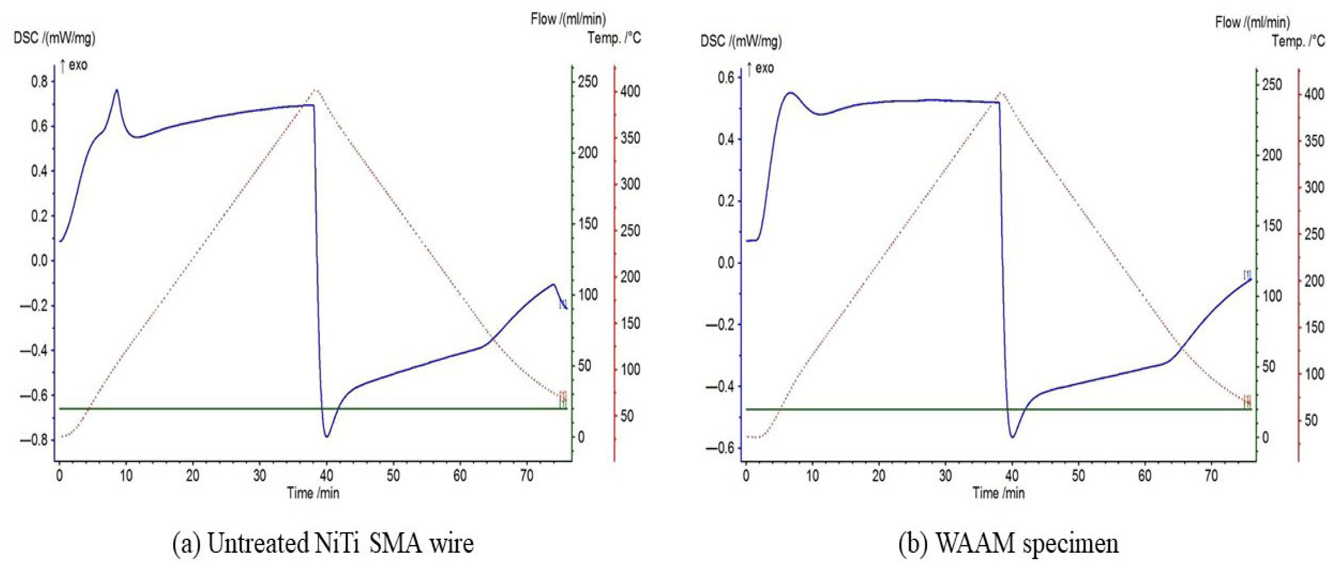
3.4. DSC Test
4. Conclusions
- The 40 layers of L-shaped structure was successfully fabricated at optimized parameters of wire feed speed at 6 m/min, travel speed at 12 mm/s, and voltage at 20 V. Identical layer-on-layer deposition was observed along with seamless fusion.
- The macrographs demonstrated the continuous bonding among the layers with complete fusion without presence of pores and cracks on the NiTi deposited corner joint.
- The microstructure in the area between the two middle layers has exhibited a mixture of columnar grains (both coarse and fine) interspersed with dendritic colonies due to extended solidification times, while the microstructure in the top most layers has exhibited finer colonial structures in relatively greater numbers.
- The microhardness (MH) test has shown the average values of 283.2 ± 3.67 HV, and 371.1 ± 5.81 HV at the bottom- and top-most layers respectively. The bottom section has shown lower MH values due to the fact that initial layers were deposited onto the cold substrate plate, along with the influence of the resulting HAZ. The overall MH values have clearly shown a consistent and identical summary for the whole built wall depicting the overall mechanical stability.
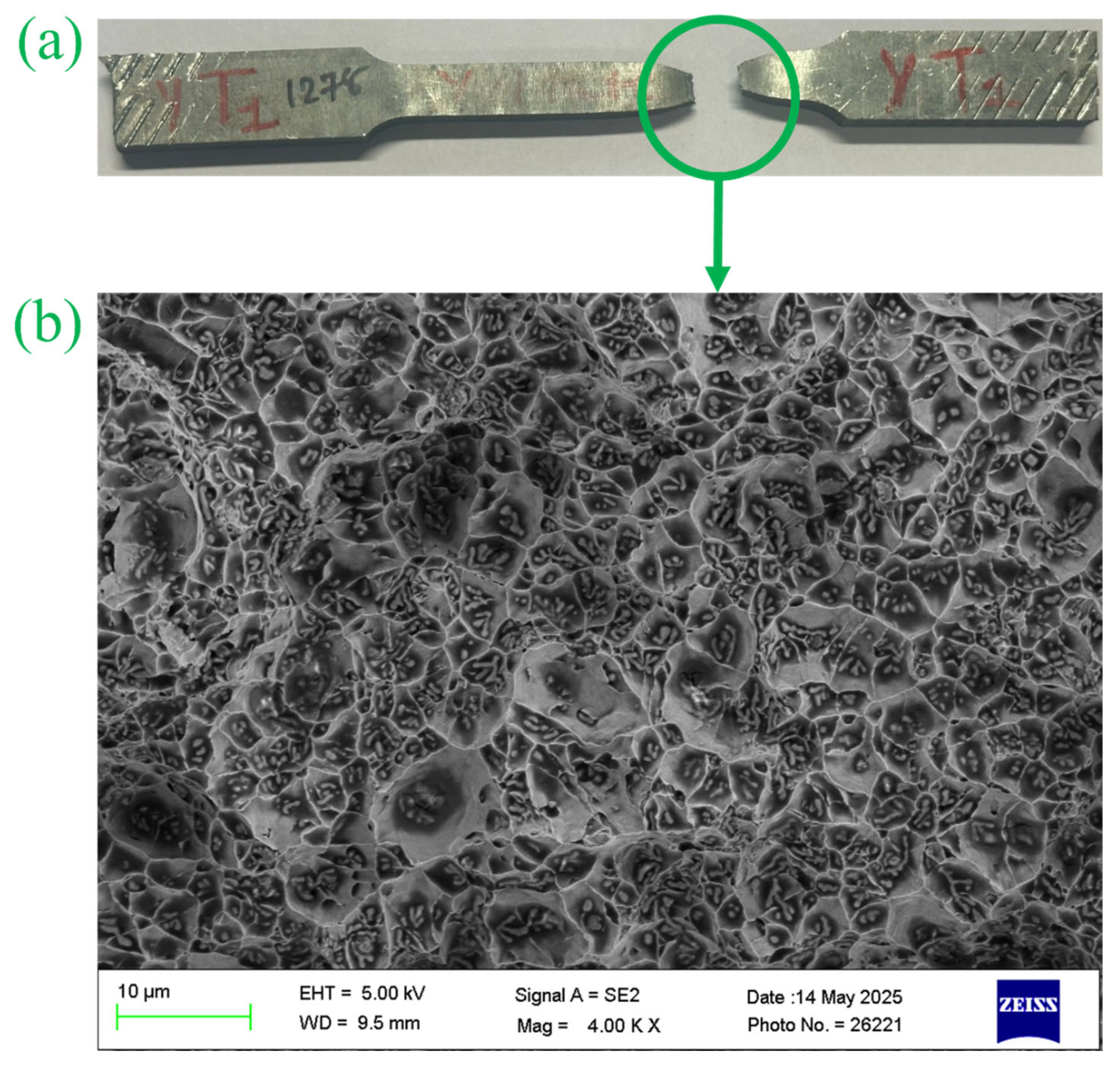
- The tensile test values attained in deposition direction have shown good tensile strength as compared to the build direction specimens. The average UTS, and EL for deposition direction was obtained as 831 ± 22.91 MPa, and 14.32 ± 0.55% respectively, while the build direction has shown average UTS and EL values of 774 ± 6.56 MPa, and 14.16 ± 0.21% respectively. The elongation exceeding 10% in all samples suggests that the fabricated structure demonstrates properties comparable to those of wrought metal. Fractography of all tensile specimens has shown good ductility and toughness.
- Lastly, a DSC test was carried out to assess the retention of shape memory effect for the fabricated structure. The transformation temperatures observed in both the base metal wire and WAAM samples were comparable, suggesting that the shape memory effect remained intact after the fabrication of the L-shaped wall structure using a GMAW-based WAAM process.
- The authors believe that the findings of this work will be valuable for various industrial applications.
Author Contributions
Funding
Data Availability Statement
Conflicts of Interest
References
- Dutta, S.; Sarma, D.K.; Vora, J.; Chaudhari, R.; Bhowmik, A.; Samal, P.; Khanna, S. A State-of-the-Art Review on Micro-Machining of Nitinol Shape Memory Alloys and Optimization of Process Variables Considering the Future Trends of Research. J. Manuf. Mater. Process. 2025, 9, 183. [Google Scholar] [CrossRef]
- Zhumabekova, A.; Toleubekova, M.; Pham, T.T.; Talamona, D.; Perveen, A. Effect of Lattice Structure on Mechanical Properties of Ti-6Al-4V-Ta Alloy for Improved Antibacterial Properties. J. Manuf. Mater. Process. 2024, 8, 133. [Google Scholar] [CrossRef]
- Ahmad, S.; Hashmi, A.W.; Singh, J.; Arora, K.; Tian, Y.; Iqbal, F.; Al-Dossari, M.; Khan, M.I. Innovations in additive manufacturing of shape memory alloys: Alloys, microstructures, treatments, applications. J. Mater. Res. Technol. 2024, 32, 4136–4197. [Google Scholar] [CrossRef]
- Kangda, M.Z.; Ubaid, A.; Sathe, S.; Wadki, V.; Razvi, S.W.N.; Raikar, R.G. Shape memory alloys: A resilient structural engineering material. Multiscale Multidiscip. Model. Exp. Des. 2025, 8, 251. [Google Scholar] [CrossRef]
- Behera, A.; Behera, A. Shape-memory materials. In Advanced Materials: An Introduction to Modern Materials Science; Springer: Cham, Switzerland, 2022; pp. 1–42. [Google Scholar]
- Chaudhari, R.; Vora, J.J.; Prabu, S.; Palani, I.; Patel, V.K.; Parikh, D. Pareto optimization of WEDM process parameters for machining a NiTi shape memory alloy using a combined approach of RSM and heat transfer search algorithm. Adv. Manuf. 2021, 9, 64–80. [Google Scholar] [CrossRef]
- Alipour, S.; Taromian, F.; Ghomi, E.R.; Zare, M.; Singh, S.; Ramakrishna, S. Nitinol: From historical milestones to functional properties and biomedical applications. Proc. Inst. Mech. Eng. Part H J. Eng. Med. 2022, 236, 1595–1612. [Google Scholar] [CrossRef] [PubMed]
- Morano, C.; Garofalo, S.; Bertuccio, P.; Sposato, A.; Zappone, I.; Pagnotta, L. A Comprehensive Literature Review of Total Hip Arthroplasty (THA): Part 1—Biomaterials. J. Funct. Biomater. 2025, 16, 179. [Google Scholar] [CrossRef] [PubMed]
- Nabila, B.; Naouel, H.; Mamoun, F.; Dikra, B.; Habeeb, M.A.; Imen, R.; Neçar, M.; Larios, A.P.; Gamal, A.E.-H.; Aleksei, O. Investigating the Tribological Behavior of Nitinol Alloys Manufactured via Mechanical Alloying for Hip Implant Applications. In Characterization of Minerals, Metals, and Materials 2025, Proceedings of the TMS Annual Meeting & Exhibition, Las Vegas, NV, 23–27 March 2025; Springer: Cham, Switzerland; pp. 403–412.
- Chaudhari, R.; Vora, J.J.; Mani Prabu, S.; Palani, I.; Patel, V.K.; Parikh, D.; de Lacalle, L.N.L. Multi-response optimization of WEDM process parameters for machining of superelastic nitinol shape-memory alloy using a heat-transfer search algorithm. Materials 2019, 12, 1277. [Google Scholar] [CrossRef]
- da Silva, T.C.; Sallica-Leva, E.; Rayón, E.; Santos, C.T.; Filho, J.C.; Volpato, N.; Lima, D.D.; Dornelas, P.H.; Tavares, S.S.; Santos, T.G. Microstructure, Thermal, and Mechanical Behavior of NiTi Shape Memory Alloy Obtained by Micro Wire and Arc Direct Energy Deposition. J. Manuf. Mater. Process. 2025, 9, 57. [Google Scholar] [CrossRef]
- Guarise, A.; Bertolini, R.; Ghiotti, A.; Bruschi, S. Wear behaviour of additively manufactured Nitinol cryogenically machined at different cutting speeds. Tribol. Int. 2025, 204, 110478. [Google Scholar] [CrossRef]
- Chaudhari, R.; Vora, J.J.; Parikh, D. A review on applications of nitinol shape memory alloy. In Recent Advances in Mechanical Infrastructure, Proceedings of ICRAM 2020, Ahmedabad, India, 21–23 August 2020; Springer: Singapore, 2021; pp. 123–132. [Google Scholar]
- Billah, T.; Aquib, T.I.; Dey, K. A review on surface modification of NiTinol for biomedical applications. J. Mater. Sci. 2024, 59, 19340–19379. [Google Scholar] [CrossRef]
- Güven, S.; Karataş, M.A.; Motorcu, A.R.; Gökkaya, H. Machinability of nickel-titanium (NiTi) shape memory alloys (SMAs): Traditional machining process. In Machining and Tribology of Advanced Materials: From Coatings, Lubrications, Surface Treatments to Modeling and Simulation; Walter de Gruyter GmbH: Berlin, Germany; Boston, MA, USA, 2025; Volume 12, p. 21. [Google Scholar]
- Vora, J.; Parikh, N.; Chaudhari, R.; Patel, V.K.; Paramar, H.; Pimenov, D.Y.; Giasin, K. Optimization of bead morphology for GMAW-based wire-arc additive manufacturing of 2.25 Cr-1.0 Mo steel using metal-cored wires. Appl. Sci. 2022, 12, 5060. [Google Scholar] [CrossRef]
- Matta, C.S.K.; Talla, G.; Hegde, K.A.; Gangopadhyay, S. Effect of Radial Force and Radial Torque on Hole Quality Characteristics During Micro-Drilling of Nitinol Shape Memory Alloy. Int. J. Precis. Eng. Manuf. 2025, 26, 1131–1140. [Google Scholar] [CrossRef]
- Muniraju, M.; Talla, G. Exploring sustainable machining processes for nitinol shape memory alloy: A review of eco-friendly EDM and other techniques. J. Braz. Soc. Mech. Sci. Eng. 2024, 46, 85. [Google Scholar] [CrossRef]
- Martínez, R.Z.; Bose-Bandyopadhyay, S.; Burl, A.; Contreras-Almengor, Ó.; Vega, C.A.; Saleeby, K.; Kurfess, T.; Lantada, A.D.; Molina-Aldareguia, J. Comparative analysis of machining and electropolishing for surface quality improvement of shape memory nitinol samples additively manufactured by laser powder bed fusion. Addit. Manuf. Lett. 2025, 12, 100261. [Google Scholar] [CrossRef]
- Ali, R.; East, D.; Murphy, A.B.; Guoxing, L.; Vanna, Y.K. Optimising Additive Manufacturing of NiTi and NiMnGa Shape Memory Alloys: A Review. Metals 2025, 15, 488. [Google Scholar]
- Moutablaleh, H.; Abdelhady, E.S.; Vaneker, T.; Gibson, I.; Mehrpouya, M. A comparative analysis of functional performance in additively manufactured NiTi, Ti-6Al-4V, and 316L stainless steel architected metastructures. J. Mech. Behav. Biomed. Mater. 2025, 169, 107071. [Google Scholar] [CrossRef]
- Kubášová, K.; Drátovská, V.; Losertová, M.; Salvetr, P.; Kopelent, M.; Kořínek, F.; Havlas, V.; Džugan, J.; Daniel, M. A review on additive manufacturing methods for NiTi shape memory alloy production. Materials 2024, 17, 1248. [Google Scholar] [CrossRef]
- Frazier, W.E. Metal additive manufacturing: A review. J. Mater. Eng. Perform. 2014, 23, 1917–1928. [Google Scholar] [CrossRef]
- El-Husseiny, M.M.; Baraka, A.A.; Oraby, O.; El-Danaf, E.A.; Salem, H.G. Fabrication of Bimetallic High-Strength Low-Alloy Steel/Si-Bronze Functionally Graded Materials Using Wire Arc Additive Manufacturing. J. Manuf. Mater. Process. 2023, 7, 138. [Google Scholar] [CrossRef]
- Khanna, N.; Salvi, H.; Karaş, B.; Fairoz, I.; Shokrani, A. Cost modelling for powder bed fusion and directed energy deposition additive manufacturing. J. Manuf. Mater. Process. 2024, 8, 142. [Google Scholar] [CrossRef]
- Abdulhameed, O.; Al-Ahmari, A.; Ameen, W.; Mian, S.H. Additive manufacturing: Challenges, trends, and applications. Adv. Mech. Eng. 2019, 11, 1687814018822880. [Google Scholar] [CrossRef]
- Zhou, L.; Miller, J.; Vezza, J.; Mayster, M.; Raffay, M.; Justice, Q.; Al Tamimi, Z.; Hansotte, G.; Sunkara, L.D.; Bernat, J. Additive manufacturing: A comprehensive review. Sensors 2024, 24, 2668. [Google Scholar] [CrossRef]
- Kahhal, P.; Jo, Y.-K.; Park, S.-H. Recent progress in remanufacturing technologies using metal additive manufacturing processes and surface treatment. Int. J. Precis. Eng. Manuf.-Green Technol. 2024, 11, 625–658. [Google Scholar] [CrossRef]
- Vora, J.; Parmar, H.; Chaudhari, R.; Khanna, S.; Doshi, M.; Patel, V. Experimental investigations on mechanical properties of multi-layered structure fabricated by GMAW-based WAAM of SS316L. J. Mater. Res. Technol. 2022, 20, 2748–2757. [Google Scholar] [CrossRef]
- Armstrong, M.; Mehrabi, H.; Naveed, N. An overview of modern metal additive manufacturing technology. J. Manuf. Process. 2022, 84, 1001–1029. [Google Scholar] [CrossRef]
- Çam, G.; Günen, A. Challenges and opportunities in the production of magnesium parts by directed energy deposition processes. J. Magnes. Alloys 2024, 12, 1663–1686. [Google Scholar] [CrossRef]
- Zhao, T.; Yan, Z.; Zhang, B.; Zhang, P.; Pan, R.; Yuan, T.; Xiao, J.; Jiang, F.; Wei, H.; Lin, S. A comprehensive review of process planning and trajectory optimization in arc-based directed energy deposition. J. Manuf. Process. 2024, 119, 235–254. [Google Scholar] [CrossRef]
- Ahn, D.-G. Directed energy deposition (DED) process: State of the art. Int. J. Precis. Eng. Manuf.-Green Technol. 2021, 8, 703–742. [Google Scholar] [CrossRef]
- Huang, L.; Chen, X.; Konovalov, S.; Su, C.; Fan, P.; Wang, Y.; Xiaoming, P.; Panchenko, I. A review of challenges for wire and arc additive manufacturing (WAAM). Trans. Indian Inst. Met. 2023, 76, 1123–1139. [Google Scholar] [CrossRef]
- Chaudhari, R.; Parmar, H.; Vora, J.; Patel, V.K. Parametric study and investigations of bead geometries of GMAW-based wire–arc additive manufacturing of 316L stainless steels. Metals 2022, 12, 1232. [Google Scholar] [CrossRef]
- Foorginejad, A.; Khatibi, S.; Torshizi, H.; Emam, S.M.; Afshari, H. Enhancement of Additive Manufacturing Processes for Thin-Walled Part Production Using Gas Metal Arc Welding (GMAW) with Wavelet Transform. Appl. Sci. 2024, 14, 9909. [Google Scholar] [CrossRef]
- Athaib, N.H.; Haleem, A.H.; Al-Zubaidy, B. A review of wire arc additive manufacturing (WAAM) of aluminium composite, process, classification, advantages, challenges, and application. J. Phys. Conf. Ser. 2021, 1973, 012083. [Google Scholar] [CrossRef]
- Resnina, N.; Palani, I.; Belyaev, S.; Prabu, S.M.; Liulchak, P.; Karaseva, U.; Manikandan, M.; Jayachandran, S.; Bryukhanova, V.; Sahu, A. Structure, martensitic transformations and mechanical behaviour of NiTi shape memory alloy produced by wire arc additive manufacturing. J. Alloys Compd. 2021, 851, 156851. [Google Scholar] [CrossRef]
- Liu, G.; Zhou, S.; Lin, P.; Zong, X.; Chen, Z.; Zhang, Z.; Ren, L. Analysis of microstructure, mechanical properties, and wear performance of NiTi alloy fabricated by cold metal transfer based wire arc additive manufacturing. J. Mater. Res. Technol. 2022, 20, 246–259. [Google Scholar] [CrossRef]
- Kumar, A.; Palani, I.A.; Yadav, M. Comprehensive study of microstructure, phase transformations, and mechanical properties of nitinol alloys made of shape memory and superelastic wires and a novel approach to manufacture Belleville spring using wire arc additive manufacturing. Mater. Today Commun. 2024, 38, 107881. [Google Scholar] [CrossRef]
- Singh, S.; Resnina, N.; Belyaev, S.; Jinoop, A.; Shukla, A.; Palani, I.; Paul, C.; Bindra, K. Investigations on NiTi shape memory alloy thin wall structures through laser marking assisted wire arc based additive manufacturing. J. Manuf. Process. 2021, 66, 70–80. [Google Scholar] [CrossRef]
- Wang, J.; Pan, Z.; Wang, Y.; Wang, L.; Su, L.; Cuiuri, D.; Zhao, Y.; Li, H. Evolution of crystallographic orientation, precipitation, phase transformation and mechanical properties realized by enhancing deposition current for dual-wire arc additive manufactured Ni-rich NiTi alloy. Addit. Manuf. 2020, 34, 101240. [Google Scholar] [CrossRef]
- Song, K.; Lin, Z.; Fa, Y.; Zhao, X.; Zhu, Z.; Ya, W.; Sun, Z.; Yu, X. Microstructure and mechanical properties of high-strength, low-alloy steel thin-wall fabricated with wire and arc additive manufacturing. Metals 2023, 13, 764. [Google Scholar] [CrossRef]
- Mai, D.S.; Doan, T.K.; Paris, H. Wire and arc additive manufacturing of 308L stainless steel components: Optimization of processing parameters and material properties. Eng. Sci. Technol. Int. J. 2021, 24, 1015–1026. [Google Scholar]
- Vaghasia, V.; Chaudhari, R.; Patel, V.K.; Vora, J. Parametric Study on Investigations of GMAW-Based WAAM Process Parameters and Effect on Microstructure and Mechanical Properties of NiTi SMA. J. Manuf. Mater. Process. 2025, 9, 58. [Google Scholar] [CrossRef]
- ASTM E8/E8M-24; Standard Test Methods for Tension Testing of Metallic Materials. ASTM Committee: West Conshohocken, PA, USA, 2001.
- ASTM E384-99; Standard Test Method for Microindentation Hardness of Materials. ASTM Committee: West Conshohocken, PA, USA, 1999.
- Dutkiewicz, J.; Rogal, Ł.; Kalita, D.; Węglowski, M.; Błacha, S.; Berent, K.; Czeppe, T.; Antolak-Dudka, A.; Durejko, T.; Czujko, T. Superelastic effect in NiTi alloys manufactured using electron beam and focused laser rapid manufacturing methods. J. Mater. Eng. Perform. 2020, 29, 4463–4473. [Google Scholar] [CrossRef]
- Li, K.; Li, D.; Liu, D.; Pei, G.; Sun, L. Microstructure evolution and mechanical properties of multiple-layer laser cladding coating of 308L stainless steel. Appl. Surf. Sci. 2015, 340, 143–150. [Google Scholar] [CrossRef]
- Kelly, S.; Kampe, S. Microstructural evolution in laser-deposited multilayer Ti-6Al-4V builds: Part II. Thermal modeling. Metall. Mater. Trans. A 2004, 35, 1869–1879. [Google Scholar] [CrossRef]
- Kumar, B.; Manickam; Sathiya, P.; Senthil, S.M. A critical review of wire arc additive manufacturing of nickel-based alloys: Principles, process parameters, microstructure, mechanical properties, heat treatment effects, and defects. J. Braz. Soc. Mech. Sci. Eng. 2023, 45, 164. [Google Scholar] [CrossRef]
- Zeng, Z.; Cong, B.; Oliveira, J.; Ke, W.; Schell, N.; Peng, B.; Qi, Z.; Ge, F.; Zhang, W.; Ao, S. Wire and arc additive manufacturing of a Ni-rich NiTi shape memory alloy: Microstructure and mechanical properties. Addit. Manuf. 2020, 32, 101051. [Google Scholar] [CrossRef]
- Yu, L.; Chen, K.; Zhang, Y.; Liu, J.; Yang, L.; Shi, Y. Microstructures and mechanical properties of NiTi shape memory alloys fabricated by wire arc additive manufacturing. J. Alloys Compd. 2022, 892, 162193. [Google Scholar] [CrossRef]
- Qi, Z.; Qi, B.; Cong, B.; Sun, H.; Zhao, G.; Ding, J. Microstructure and mechanical properties of wire + arc additively manufactured 2024 aluminum alloy components: As-deposited and post heat-treated. J. Manuf. Process. 2019, 40, 27–36. [Google Scholar] [CrossRef]
- Wang, L.; Xue, J.; Wang, Q. Correlation between arc mode, microstructure, and mechanical properties during wire arc additive manufacturing of 316L stainless steel. Mater. Sci. Eng. A 2019, 751, 183–190. [Google Scholar] [CrossRef]
- Gao, C.; Chen, X.; Su, C.; Chen, X. Location dependence of microstructure and mechanical properties on wire arc additively manufactured nuclear grade steel. Vacuum 2019, 168, 108818. [Google Scholar] [CrossRef]
- Wu, W.; Xue, J.; Wang, L.; Zhang, Z.; Hu, Y.; Dong, C. Forming process, microstructure, and mechanical properties of thin-walled 316L stainless steel using speed-cold-welding additive manufacturing. Metals 2019, 9, 109. [Google Scholar] [CrossRef]
- Bae, J.; Lee, H.; Seo, D.; Yun, S.; Yang, J.; Huh, S.; Jeong, H.; Noh, J. Grain size and phase transformation behavior of TiNi shape-memory-alloy thin film under different deposition conditions. Materials 2020, 13, 3229. [Google Scholar] [CrossRef] [PubMed]
- Wang, F.; Williams, S.; Colegrove, P.; Antonysamy, A.A. Microstructure and mechanical properties of wire and arc additive manufactured Ti-6Al-4V. Metall. Mater. Trans. A 2013, 44, 968–977. [Google Scholar] [CrossRef]
- Wu, W.; Xue, J.; Zhang, Z.; Yao, P. Comparative study of 316L depositions by two welding current processes. Mater. Manuf. Process. 2019, 34, 1502–1508. [Google Scholar] [CrossRef]
- Zhang, K.; Wang, S.; Liu, W.; Shang, X. Characterization of stainless steel parts by laser metal deposition shaping. Mater. Des. 2014, 55, 104–119. [Google Scholar] [CrossRef]
- Chaudhari, R.; Parikh, N.; Khanna, S.; Vora, J.; Patel, V. Effect of multi-walled structure on microstructure and mechanical properties of 1.25 Cr-1.0 Mo steel fabricated by GMAW-based WAAM using metal-cored wire. J. Mater. Res. Technol. 2022, 21, 3386–3396. [Google Scholar] [CrossRef]


| Variables | Optimal Value |
|---|---|
| Wire feed speed (m/min) | 6 |
| Travel speed (mm/s) | 12 |
| Voltage (V) | 20 |
| Dwell time (s) | 45 |
| Argon gas flow (L/min) | 15 |
| Filler wire | NiTi wire with 1.2 mm dia. |
| Substrate plate | Titanium |
| Specimen | UTS, MPa | EL, % | |
|---|---|---|---|
| Deposition direction (Horizontal) | H-1 | 811 | 14.21 |
| H-2 | 826 | 13.83 | |
| H-3 | 856 | 14.92 | |
| Average | 831 ± 22.91 | 14.32 ± 0.55 | |
| Built direction (Vertical) | V-1 | 781 | 14.38 |
| V-2 | 768 | 13.97 | |
| V-3 | 773 | 14.14 | |
| Average | 774 ± 6.56 | 14.16 ± 0.21 | |
| Specimens | As (°C) | Af (°C) | Ms (°C) | Mf (°C) |
|---|---|---|---|---|
| NiTi SMA wire | 55 | 95 | 85 | 45 |
| WAAM sample | 49 | 88 | 78 | 42 |
Disclaimer/Publisher’s Note: The statements, opinions and data contained in all publications are solely those of the individual author(s) and contributor(s) and not of MDPI and/or the editor(s). MDPI and/or the editor(s) disclaim responsibility for any injury to people or property resulting from any ideas, methods, instructions or products referred to in the content. |
© 2025 by the authors. Licensee MDPI, Basel, Switzerland. This article is an open access article distributed under the terms and conditions of the Creative Commons Attribution (CC BY) license (https://creativecommons.org/licenses/by/4.0/).
Share and Cite
Vaghasia, V.; Chaudhari, R.; Khanna, S.; Modi, J.; Vora, J. Experimental Investigations on Microstructure and Mechanical Properties of L-Shaped Structure Fabricated by WAAM Process of NiTi SMA. J. Manuf. Mater. Process. 2025, 9, 239. https://doi.org/10.3390/jmmp9070239
Vaghasia V, Chaudhari R, Khanna S, Modi J, Vora J. Experimental Investigations on Microstructure and Mechanical Properties of L-Shaped Structure Fabricated by WAAM Process of NiTi SMA. Journal of Manufacturing and Materials Processing. 2025; 9(7):239. https://doi.org/10.3390/jmmp9070239
Chicago/Turabian StyleVaghasia, Vatsal, Rakesh Chaudhari, Sakshum Khanna, Jash Modi, and Jay Vora. 2025. "Experimental Investigations on Microstructure and Mechanical Properties of L-Shaped Structure Fabricated by WAAM Process of NiTi SMA" Journal of Manufacturing and Materials Processing 9, no. 7: 239. https://doi.org/10.3390/jmmp9070239
APA StyleVaghasia, V., Chaudhari, R., Khanna, S., Modi, J., & Vora, J. (2025). Experimental Investigations on Microstructure and Mechanical Properties of L-Shaped Structure Fabricated by WAAM Process of NiTi SMA. Journal of Manufacturing and Materials Processing, 9(7), 239. https://doi.org/10.3390/jmmp9070239