1. Introduction
Intramuscular injection is one of the most commonly used techniques for the indirect parenteral administration of liquid drug dosage forms. This method involves injecting a specific substance into muscle tissue using a needle and syringe.
However, intramuscular administration presents several critical safety concerns for both the patient and the healthcare professional. These include the potential for incomplete drug delivery and the biological risk posed to healthcare workers due to accidental needle punctures [
1,
2] and other complications including nerve damage, tissue necrosis, intramuscular hemorrhage, abscesses, intravascular injection [
3]. Using the clinical practice that prevents injected fluid from entering a blood vessel involves aspiration prior to injection, with established aspiration times and pressure maintenance, blood would be observed in the syringe if a vein had been punctured. The speed of administration is also associated with pain [
4]. Therefore, if these processes are automated and variability among healthcare providers is avoided, the quality of administration is improved.
Fear of needles is another issue that the design of this device is intended to address. In a systematic review of 119 references [
5], important aspects such as refusal to vaccinate oneself or one’s children, the non-continuation of treatments, including oncological treatments, or avoiding medical studies involving blood collection have been highlighted. A study in Japan [
6] shows how cognitive interventions that explain needle procedures can reduce this fear of needles and greatly facilitate vaccination. A safe device can help in this context, as the authors point to the limited literature on the preparedness of healthy children receiving multiple vaccinations outside of hospitals. This aspect of preparedness is particularly important for children with autism-spectrum disorders. There has also been an analysis of how small declines in vaccination rates can have a large impact on public health spending [
7].
In this situation, to reduce the risk of accidental punctures and increase the chances of safe administration, a reusable device for the intramuscular injection of liquids has been designed, with reliable and low-cost technology. A multidisciplinary team, consisting of healthcare professionals and engineers, collaborates to define design specifications and verify the functionality of the final prototype. Thanks to its design, the device improves the efficiency of clinical practice by offering a safer, faster, and more automated system, thus eliminating the variability in the current administration of injections between different healthcare professionals. The device helps to standardize and improve this clinical practice. Two models have been developed: one manual and one automated.
The purpose of this study is to design a device that assists in the precise dosing of personalized medication for intramuscular injections using a syringe [
8] while ensuring simple and safe operation for both healthcare professionals and patients. The medical device is subject to regulatory requirements and classified as Class I [
9].
Throughout the project, various design challenges must be addressed, alongside technical considerations such as determining the force required for dosing. These factors depend on the syringe and needle size, needle length, the viscosity of the administered liquids, and the control of dosing time.
Three-dimensional printing and its ease of prototyping facilitates communication between healthcare professionals and engineers in the innovation of procedures or techniques. New materials and shapes that are difficult to obtain through traditional procedures now facilitate the development of devices applicable in the medical field. These applications cover a wide spectrum, from the preparation of operations to the simulation of organs, teaching materials or, as in this case, the creation of functional prototypes that facilitate the process of transfer to industry [
10,
11,
12,
13,
14,
15,
16].
This manuscript presents a clear example of the application of rapid prototyping and solid modeling in the design of new healthcare products.
2. Materials and Methods
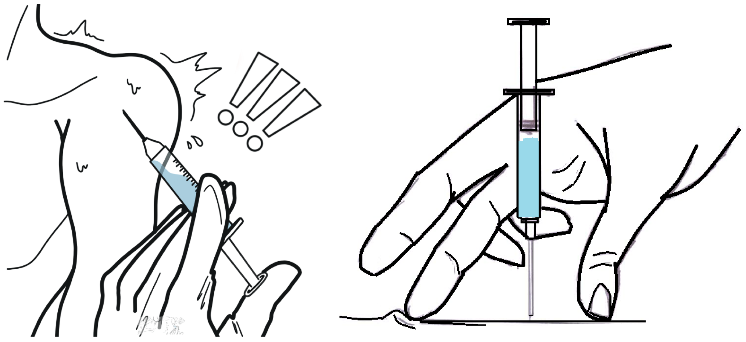
Figure 1 illustrates the handling of the syringe once it has been loaded with the correct dose of medication. This procedure must be performed with the needle exposed to air, posing a risk of accidental punctures for both patients and healthcare workers. Additionally, in some cases, before administering the medication, the healthcare worker must verify that the needle has not punctured a vein. This requires a suction process, and if no blood is detected, the syringe plunger is then pushed to deliver the correct dosage. Since higher injection speeds can cause increased pain, the administration process depends on the skill and technique of each healthcare professional [
17,
18,
19].
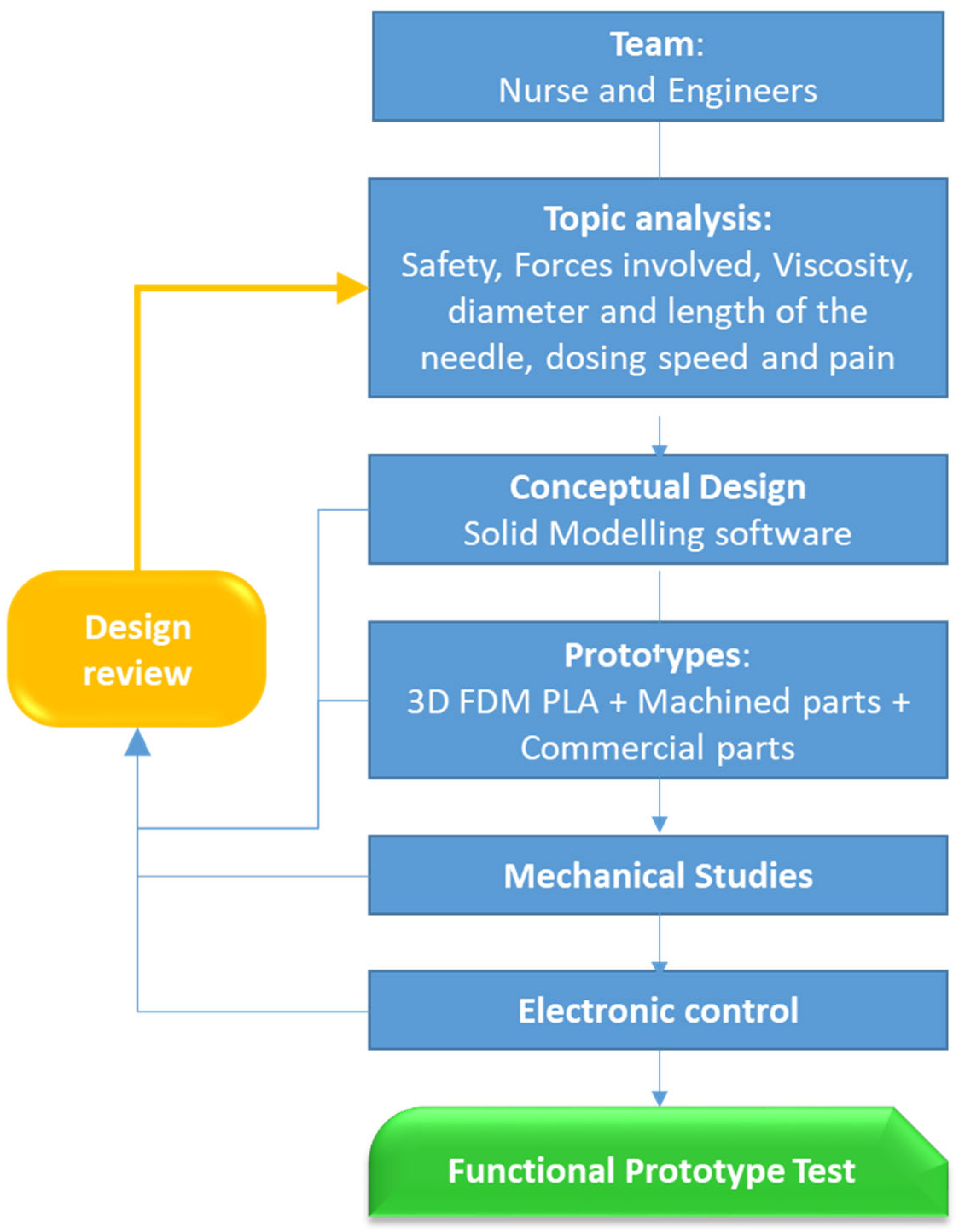
For the development of this study, meetings were held between healthcare professionals and engineers to establish the device’s design requirements. Consideration was given to the device’s ease of use, regardless of which hand, and the ability to use the other hand on the patient. Appropriate administration speeds, the timing of a correct dose that avoids side effects and minimizes pain, a technique that prevents the fluid from ultimately entering a blood vessel, and ensuring the syringe needle is protected throughout the entire process were studied. The fulfillment of these objectives requires a study of the fluids to be injected and the various components, whether manufactured by FDM, machined, or commercially available. In each of the stages of the process, we have been advised by a company in the health sector. The work scheme can be seen in
Figure 2.
During previous team meetings, healthcare professionals highlighted several key aspects of intramuscular injection administration that could be considered for future improvements to the basic device.
In the proposed design, we have worked on a device with needle protection during the whole process, and that guarantees a dosing time adequate to the volume of the drug to minimize the sensation of pain. This device exerts an adequate force depending on the viscosity of the drug and the size (diameter and length) of the needle. These considerations are well known among medical professionals, who apply them according to their expertise and judgment.
In this study, the viscosities of five different medications were analyzed, measuring their viscosity at three temperatures: 20 °C, 30 °C, and 40 °C (see 3.2.4. Drug Viscosity). An SVM 3001 Kinematic viscometer was used.
Based on these considerations, two prototype devices have been designed and developed as proposed alternatives to traditional intramuscular injection methods:
- 1.
A simple, low-cost model mechanically driven by a compression spring for the dosing mechanism.
- 2.
A second model incorporating a linear actuator for automated operation.
In both designs, the needle-protection system is inspired by existing self-injection devices, such as those used for diabetes [
20,
21], and utilizes a compression spring.
In the design phase we are currently in, a mixed system has been chosen for the manufacture of these prototypes. Thus, the housings, needle protector, body, and cover of the devices have been obtained by additive manufacturing, using a BCN3D printer that operates with PLA, to which the CAD files are sent in .stl format. The default parameters recommended by the manufacturer for their own material have been utilized. Machined parts have been used for the trigger and the aluminum-dosing piston. Finally, the springs and the linear actuator are commercially available parts.
According to Regulation (EU) 2017/745, the injection delivery devices shown here are classified as follows:
Therefore, there is no biocompatibility issue with the materials.
3. Results
This section includes subsections relating to device design criteria and studies carried out that have influenced the components and electronic control.
3.1. Solid Modeling of the Device
Following the specified design guidelines, a preliminary design was initially undertaken using SolidWorks(R) 2023 software. The 3D images allow for improved communication with the healthcare team regarding possible modifications.
The mechanical and electromechanical devices with their components are presented below.
3.1.1. Mechanically Driven Model with Compression Spring for Dosing
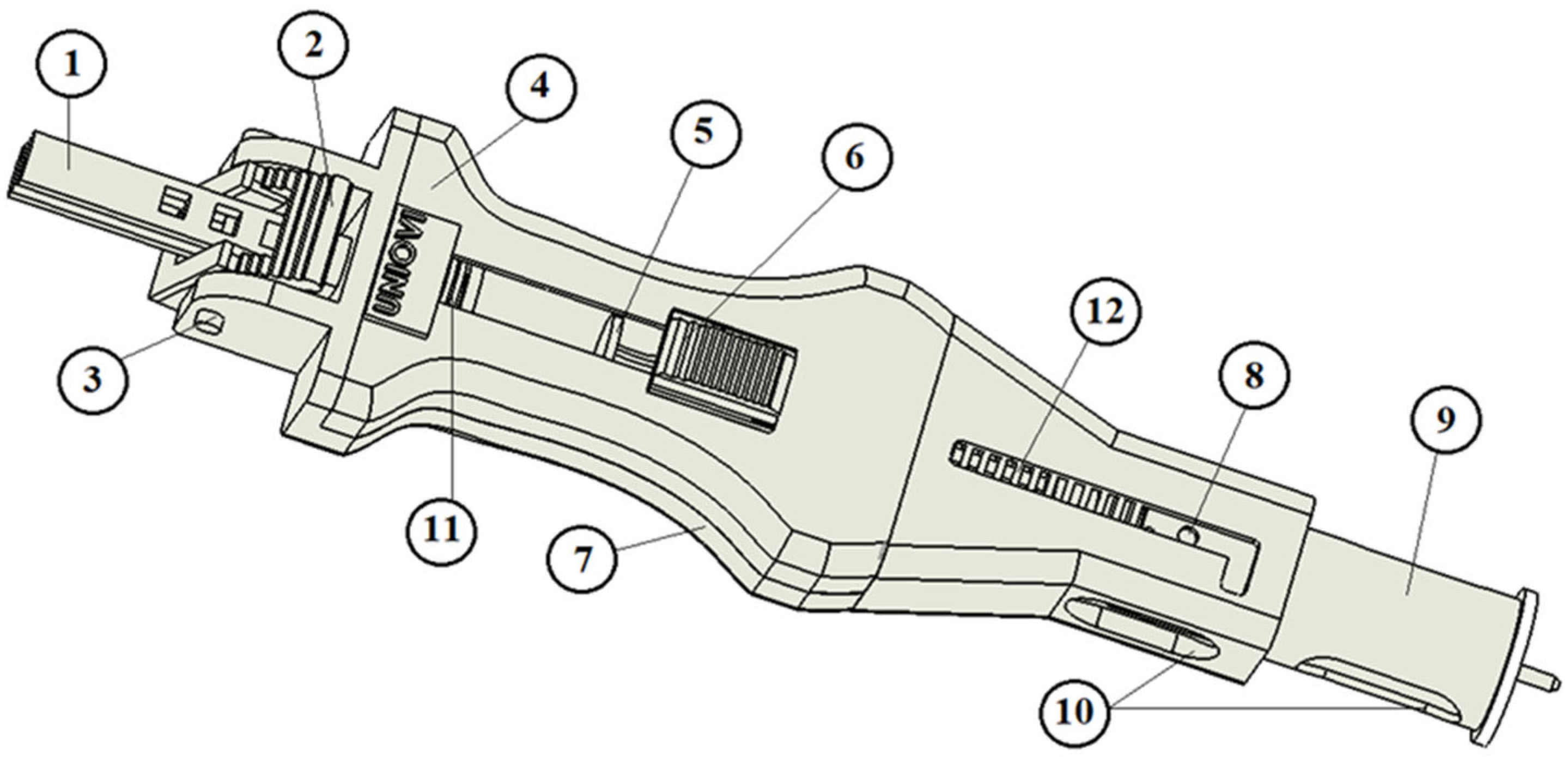
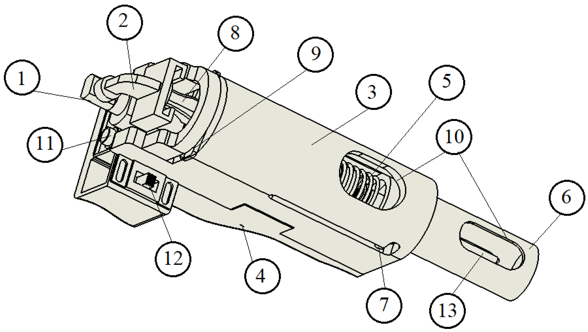
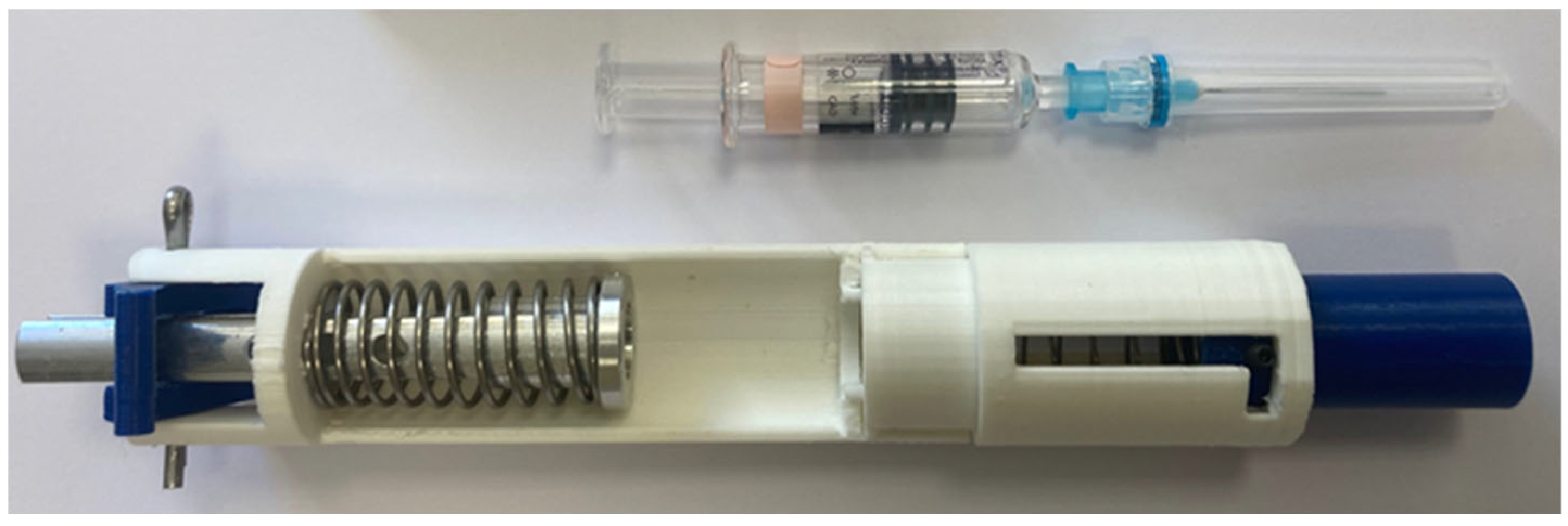
In addition to being a functional device, the design prioritizes ergonomics, ensuring ease of use with one hand for both right- and left-handed users. The device features rounded edges to eliminate sharp corners. In the initial prototypes (see
Figure 3), all components—except for the springs—were manufactured using fused deposition modeling (FDM) for preliminary testing.
These initial models allowed us to validate the functionality of the proposed design, adjust dimensions for improved one-handed operation, and identify critical components.
Before constructing the prototypes, it was necessary to determine the appropriate size (dimensions and spring constant) of the springs used, which will be explained in
Section 3.2.4. This component is crucial, as it transmits the necessary force for dosing through the plunger and the device body. Although the required force is relatively low (approximately 5 to 12 N), it indicated that at least three of the components could not be manufactured using FDM in the final prototypes [
22,
23]: the dosing plunger, (1) in
Figure 3, and the dosing trigger and the trigger joint, (2) and (3) in
Figure 3. In the final model, these components are fabricated from aluminum.
3.1.2. Electromechanically Driven Model with Linear Actuator for Dosing
In addition to the main components shown in
Figure 4, the device also includes wiring to connect the 9-volt batteries and the linear actuator, as well as a control board located beneath the cover.
Figure 3 and
Figure 4 depict one model for each type of device (spring-loaded or linear actuator-driven). However, these representations may not reflect the final design. We are collaborating with a private company that employs industrial designers, who will refine the final version in accordance with the operating principles outlined in this article.
3.2. Forces Involved in the Injection Process and Selection of the Compression Spring
3.2.1. Description of the Intended Operating Mode of the Spring-Loaded Device
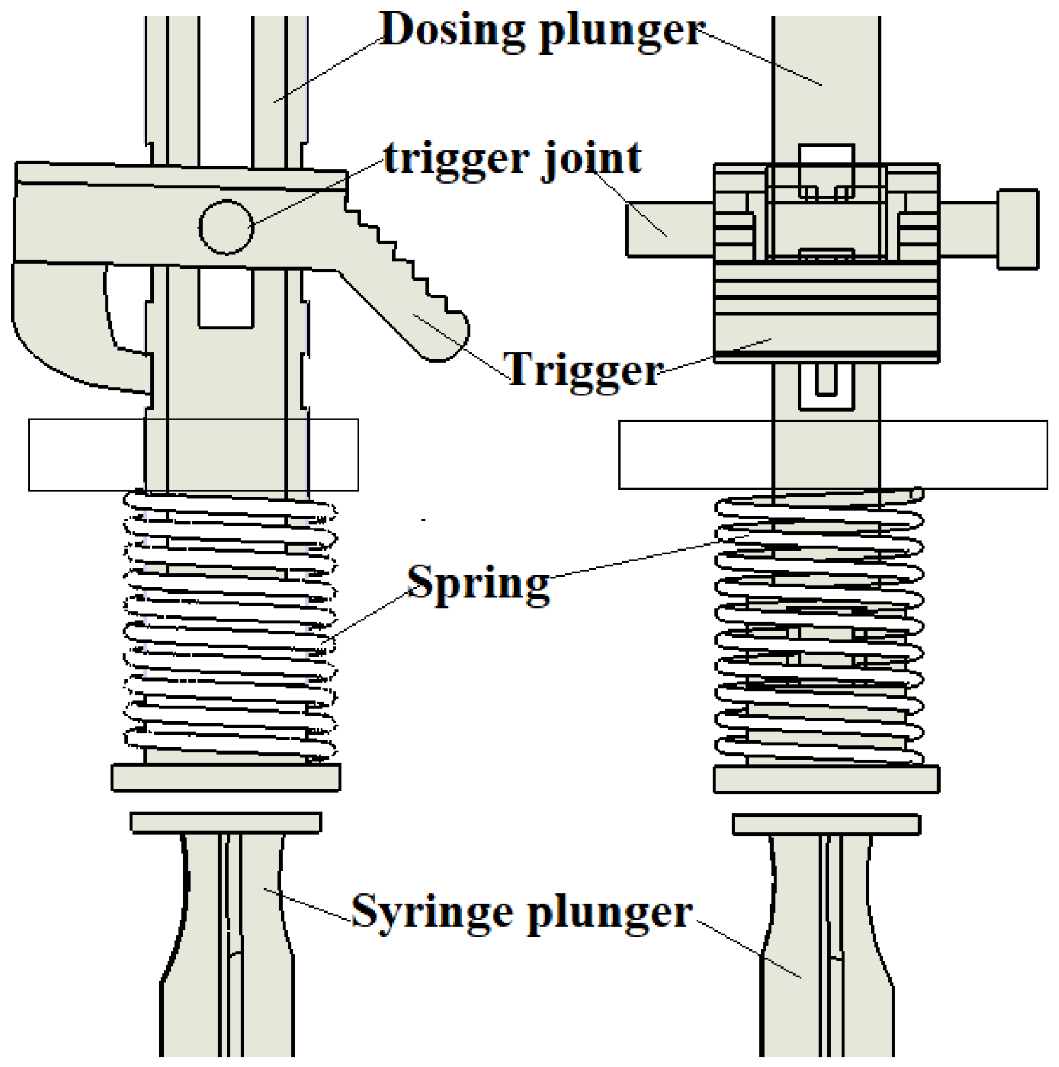
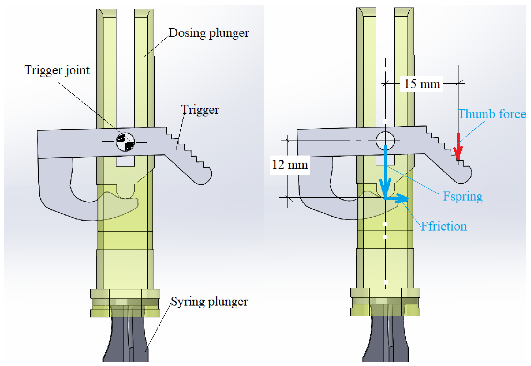
The dosing force is provided by a compression spring (
Figure 5). To ensure safe and smooth operation with minimal trigger activation force exerted by the nurse’s thumb, the spring’s force vector should be aligned with the trigger joint and the point of contact between the trigger and the dosing plunger.
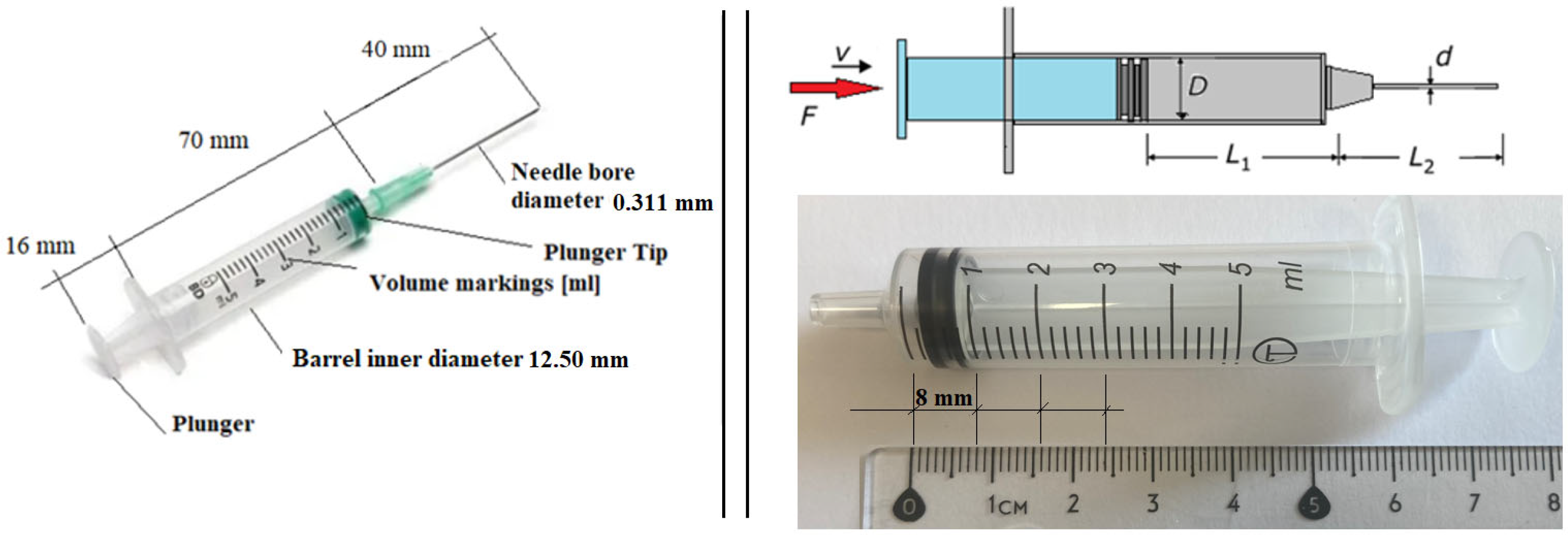
The device has been designed for use with a standard disposable pharmacy syringe made of plastic, costing approximately EUR 0.75 per unit. The syringe has a 5 mL capacity, an external diameter of 14 mm, and a needle length ranging from 40 to 50 mm. The inner needle diameter typically measures 0.311 mm (gauge 24, gray color) or 0.514 mm (gauge 21, green color).
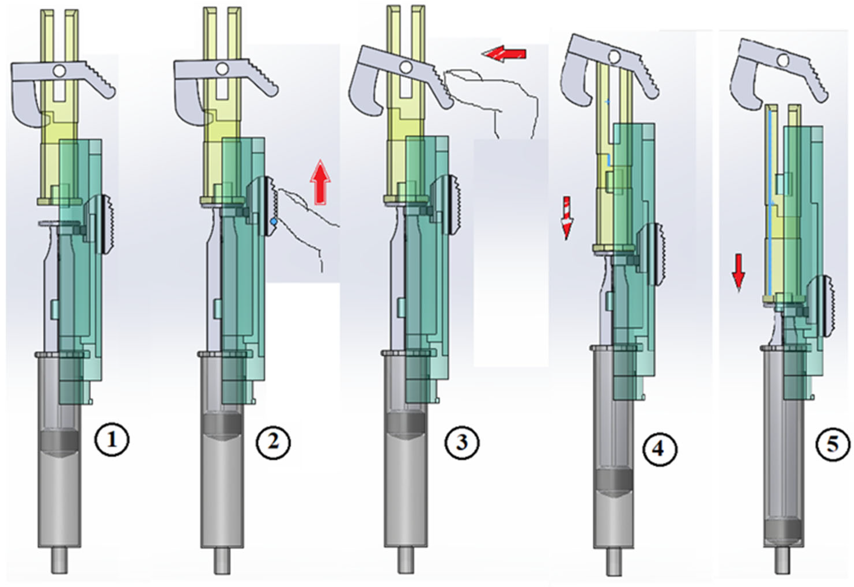
Figure 6 illustrates the suction sequence followed by trigger activation for dosing.
Initially, the device was conceived for a 3.5 mL dose, the most commonly used by the nursing service in a psychiatric consultation, where one of the team members was working. In this prototype, the dosing plunger was prepared for three dose options: 1.5 mL, 2.5 mL, and 3.5 mL. With the current design, the distance between the holes in the plunger (where the end of the trigger is housed) is 8 mm, though other dimensions are possible.
Use mode:
The nurse inserts the needle into the patient’s body,
To verify that the needle has not punctured a vein, a suction step is performed.
Figure 6 (2).
The suction button is pressed until the syringe plunger makes contact with the device’s dosing plunger. At this moment, the suction window,
Figure 3 (10), should be checked:
If red, indicating blood in the syringe, the process must be stopped.
If no blood is detected, it is possible to proceed with dosing.
If no blood is present after suction, the trigger button is pressed,
Figure 6 (3), initiating the dosing process seen in
Figure 6 (4) and (5).
- 4.
Needle Protection and Completion:
Once the syringe is removed from the patient’s body, the needle-protection sliding cylinder automatically moves to cover the needle.
The protection cylinder is then rotated clockwise, locking it in place, thereby ensuring needle safety and completing the procedure.
3.2.2. Forces Required for Dosing
The viscosity of different drugs can vary greatly depending on whether they are water-based or oil-based. Particularly difficult to administer are slow-release drugs, for example for monthly doses, whose viscosity is very high. A critical aspect of this prototype is the size of the dosing spring. Before selecting a spring for testing, we can estimate the required force for dosing [
24,
25].
At this stage, we require certain characteristics of the medication to be administered with the device. Since the specific medication is not yet determined and different drugs may be used, our clinical partner suggested assuming properties similar to those of water. Therefore, for this initial force estimation, we consider the following parameters (
Figure 7):
Needle diameter: 0.311 mm;
Needle length (L2): 40 mm;
Viscosity (ν): 0.98 mPas;
Density (ρ): 980 kg/m
3.
Figure 7.
A disposable syringe with a capacity up to 5 mL; needle G21.
Figure 7.
A disposable syringe with a capacity up to 5 mL; needle G21.
The dosing speed is also a crucial factor. According to good clinical practice guidelines, the fluid should be injected slowly to minimize patient discomfort.
Given a syringe plunger diameter (D) of 12.50 mm, the corresponding plunger displacement for a 3.0 mL dose (L1) is 24 mm.
For this analysis, we assume a dosing time of 6 s per ml, resulting in a total of 18 s for a 3.0 mL dose. Therefore, the considered dosing speed is 1.33 mm/s.
The syringe is assumed to be in a horizontal position. If this is not the case, the variation in dimensions due to inclination could be considered, although this effect would be minimal. However, it can be easily calculated if the syringe’s angle of inclination is known, with the limit case being a fully vertical position.
If the outlet is exposed to the atmosphere, the relative pressure at the outlet will be zero. However, there is an uncertainty in this assumption, as the needle is inserted into human tissue, where the conditions may differ. This aspect can be experimentally verified once a physical prototype is built.
From the plunger velocity, we apply the continuity equation, assuming negligible losses around the plunger tip. Under these conditions, the flow rate remains constant between the syringe plunger and the needle, which can be expressed as:
Q = Flow rate;
V = plunger velocity;
A = plunger tip area;
D = plunger tip diameter;
d = interior needle diameter;
∆P = pressure drop;
μ = water dynamic viscosity, 0.000891 kg/ (m·s).
Since the flow is laminar, the Hagen–Poiseuille equation can be applied. This equation is used in the needle region to determine the pressure drop required to achieve the previously calculated flow rate:
The flow rate (Q) is directly related to the pressure drop (ΔP) that occurs in the system. In the plunger region, the pressure is assumed to be constant. Thus, the pressure drop in the needle region can be explicitly determined using the Hagen–Poiseuille equation:
Therefore, since the pressure at the outlet is atmospheric, the pressure in the plunger region can be expressed as:
By calculating the Reynolds number, a value of Re = 1500 is obtained, confirming that the flow is indeed laminar:
The losses due to flow contraction from the plunger region to the needle region should be considered, along with the potential friction between the plunger and the syringe wall (at the plunger tip). However, with these calculations, we now have a clear estimation of the required force. The next step is to experimentally validate this force using a simple prototype and a dynamometer.
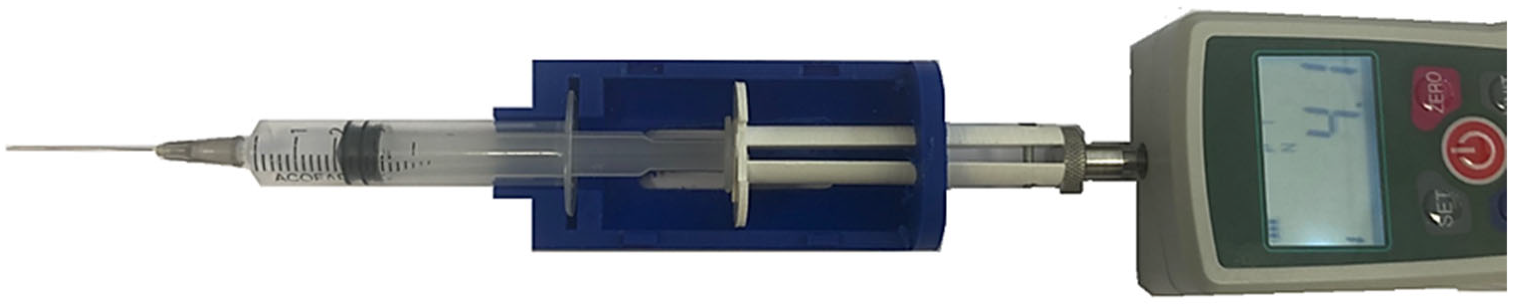
Using water, we measured the force required to administer the dose with the syringe by applying direct pressure with a dynamometer (
Figure 8). The effect of the dosing rate is immediately noticeable: when moving slowly, the peak force is approximately 4 N. Additionally, it is observed that once the initial movement is initiated, the force values decrease and stabilize, remaining close to the theoretical predictions.
3.2.3. Springs for the Prototype
Based on the theoretical and experimental values of the required dosing force, and considering the chosen design and the dimensions of the commercial syringe used, we decided to test multiple spring configurations. In the initial prototype, manufactured using FDM technology, we adjusted the dimensions to accommodate three different load capacities: V1 = 1.5 mL; V2 = 2.5 mL; and V3 = 3.5 mL.
The choice to work with these three dosing capacities is determined by the dimensions of the trigger, which must be housed in grooves located at the back of the firing plunger. For the specified volumes, this requires a slot spacing of 8 mm, making it feasible to machine these slots (4 mm diameter holes) while ensuring a proper fit for the trigger. Thus, the housing of the syringe and the dosing plunger inside the device determines the required length of the dosing spring, as shown in
Figure 9.
In this design, the total available length for the spring is 46 mm. At this length, the plunger tip reaches the end of the syringe barrel, ensuring that the entire liquid volume of the syringe is expelled.
Depending on the dosed volume, the compressed spring length should be:
35 mm, corresponding to 1.375 mL capacity;
27 mm, corresponding to 2.375 mL capacity;
19 mm, corresponding to 3.375 mL capacity.
If suction is required to ensure the needle is not inside a vein, the dosed volume changes (
Table 1):
In the theoretical calculations, a constant dosing speed was assumed, leading to a constant force value. However, in compression springs, the spring constant defines the relationship between compression length and force, meaning that the force exerted by the spring varies with the degree of compression. As a result, the maximum force is applied at the beginning of the movement (when the spring is fully compressed), and the minimum force at the end of the plunger stroke. Similarly, the dosing speed will vary proportionally to the force exerted.
Taking these considerations into account, we have selected a spring for testing. Since we cannot use most drugs for initial testing, but water presents no restrictions, we have chosen a spring suitable for dosing water. Our objective is to adjust the spring force to achieve a dosing speed between 6 and 10 s per ml.
For this test, we used a compression spring with the following specifications:
Free length (L0): 60 mm;
External diameter (D): 16 mm;
Wire diameter (d): 0.7 mm;
Measured spring constant (k): 0.1 N/mm.
Table 2 presents the measured mean time for each dosing capacity. While the measured time is not always identical across trials, the variability observed in the five tests conducted is relatively small. This suggests that the dosing process using the device is likely to be more consistent than manual dosing, where a person applies force to the syringe plunger. Furthermore, variability is expected to be even greater when different individuals perform the dosing manually.
In summary, for this case (using water and the defined spring) the dosing time is approximately 6 s per milliliter. As previously mentioned, a slower injection rate is generally associated with reduced pain for the patient.
3.2.4. Drug Viscosity
Viscosity, injection volume, and injection flow rate play a crucial role in injection pain tolerance [
26]. In this study, viscosity is a key parameter influencing both the final force required and the dosing time.
At this stage, we have selected several medications commonly administered via intramuscular injection. Since viscosity values are not typically included in medication specifications, we will measure the viscosity experimentally and later test the corresponding dosing time using our device. Viscosity is a significant challenge in the administration of new medical formulations requiring syringe-based dosing [
27]. In all cases, the drug leaflet specifies that the medication should not be stored at temperatures above 25 °C. This implies that the most relevant viscosity measurement for practical use will be at 20 °C, as it represents the worst-case scenario for dosing performance. The result of this study is shown in
Table 3 and
Figure 10.
In our design, all springs should have the same external diameter (D = 16 mm) and total length (L = 60 mm). However, we can vary the wire diameter and the mechanical properties of the steel to achieve a spring constant as defined in
Table 4, ensuring a dosing time of approximately 10 s per milliliter (within the range of 6 to 10 s per milliliter). As previously mentioned, this value must be specified, even though, in actual healthcare settings, dosing speed may vary between nurses.
3.2.5. Force on the Trigger
The trigger must be designed to securely hold the plunger of the device, which is actuated by the dosing spring (
Figure 11). The force exerted by the spring depends on both its constant and the degree of compression. In all the tests conducted, this force has been found to be relatively small and easy to apply for any user. If necessary, the geometry of the trigger can be modified to optimize functionality.
In
Table 4, the forces and distances related to the firing of the trigger are represented, and if we study the numbers for the worst case analyzed, 3.5 mL capacity for the medicine “Flufenazina decanoato” with the maximum force exerted of Fmax = 38.28 N, the maximum force exerted is calculated as follows:
This value is relatively low and can be easily exerted by any user [
28].
3.3. Model Fit for Non-Suction Vaccines
This model can be readily adapted for vaccine administration, where doses are generally smaller and pre-filled syringes with shorter, smaller-diameter needles are commonly used (
Figure 12). Modifications to the original design are required to accommodate the reduced syringe and needle dimensions. Additionally, two alternative models with minor external variations in shape have been proposed. The operational mechanism remains consistent with the dispenser illustrated in
Figure 2. Furthermore, the use of shorter needles eliminates the need for suction, thereby simplifying the overall design.
3.4. Model with Linear Actuator for Dosing, Design Specifications
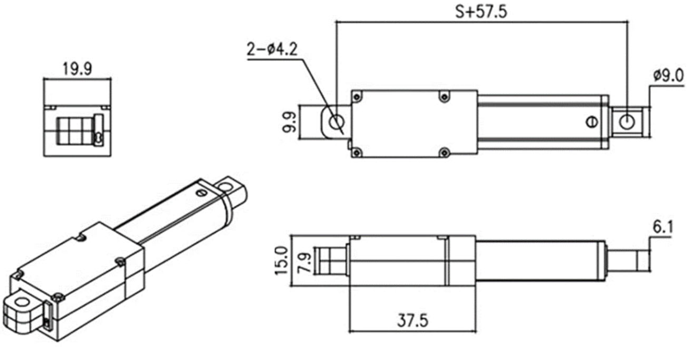
In this case, the dosing speed and force are controlled by a linear actuator. Several models are available for this purpose, and we specifically sought one with compact dimensions that would allow for integration into a relatively small device. The primary objective was to ensure ease of use, enabling one-handed operation.
The selected actuator has the dimensions shown in
Figure 13, with a stroke of 50 mm, a speed of 1.5 mm/s at 12 V, and a force capacity of 70 N. In our prototype, we use a 9 V battery, which reduces the speed to 1.12 mm/s. Consequently, for a 3.5 mL dose, given that the syringe barrel length is 24 mm, the estimated dosing time is 21 s (approximately 7.1 s per mL).
Currently, we are developing an electronic control card to adjust the actuator speed, allowing for precise dosing times tailored to each specific medication.
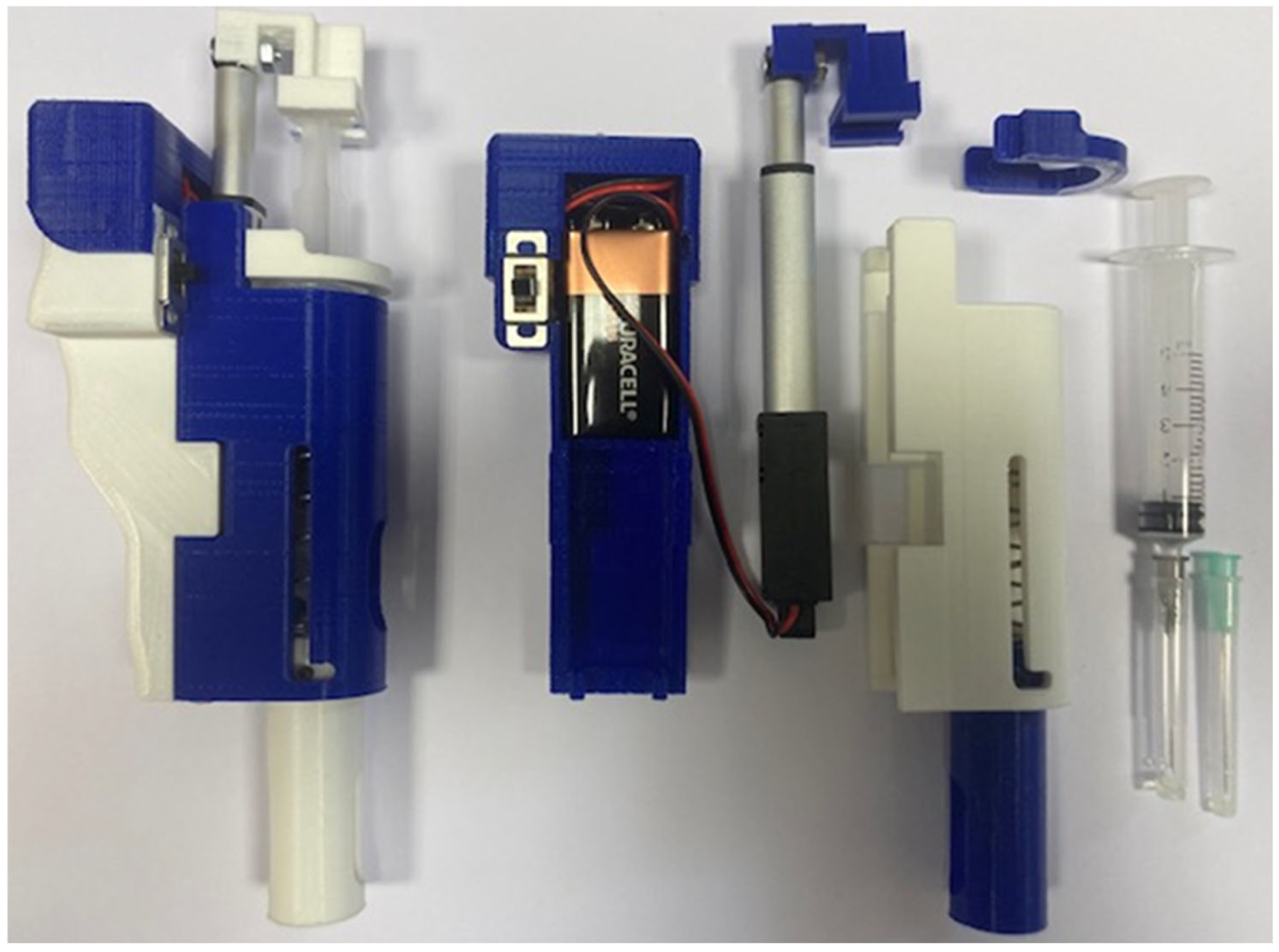
Regarding the adaptation of the spring-loaded device, the needle-guard sliding cylinder remains spring-operated. Additionally, the linear actuator and battery will be positioned parallel to the syringe to optimize space and usability.
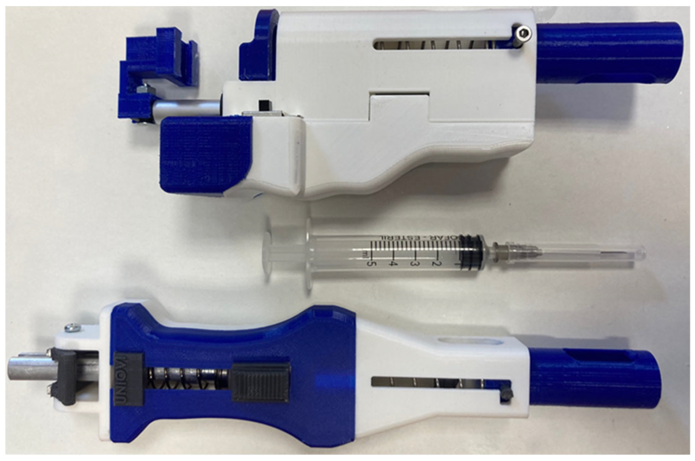
Figure 14 presents a view of the assembled device, with the needle protection positioned on the left side. The central section displays the individual components, including the syringe, battery, and linear actuator. On the right, the front view of the fully assembled device is shown.
4. Discussion
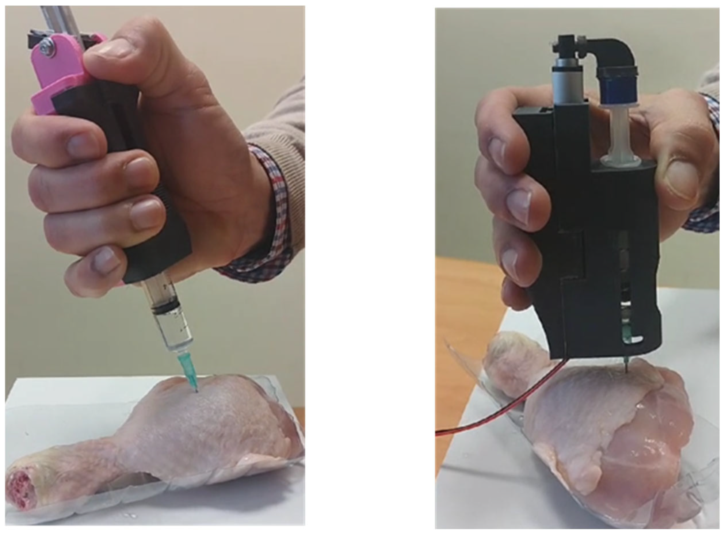
The two described devices are currently undergoing testing under conditions that closely simulate real-world scenarios. A chicken thigh is being used as a model to replicate the resistance of human tissue, and doses of 1.0 mL, 2.0 mL, and 3.0 mL of medication with known viscosity are being administered.
The optimal dosing time remains somewhat unclear. Nurses generally report that faster injections tend to cause more pain, leading to the consensus that medication should be administered slowly. However, determining the precise optimal dosing speed is complex. The literature suggests an injection time between 6 and 10 s per milliliter, but in clinical practice, this may vary depending on the medication and dose volume. Given this variability, nurses’ experience plays a crucial role in adjusting injection speed. For our device, we aim to maintain the criterion of approximately 6 to 10 s per milliliter in future developments.
Regarding the six medications analyzed in this study, for Haloperidol and Levomepromazine, whose dynamic viscosity is comparable to that of water, the same spring-loaded device used for water (as detailed in
Table 1) can be employed. For Diazepam, which has a dynamic viscosity of 7.15 mPa·s, we conducted dosing tests using a spring with dimensions D × d × L = 16 × 1 × 60 mm. The measured dosing time was approximately 8 s per milliliter (see
Table 4).
We are still in the process of identifying the optimal spring size for Zuclopenthixol and Fluphenazine decanoate, both of which have higher dynamic viscosities. We have identified and tested several spring configurations; however, in these cases, the maximum force required (see
Table 4) approaches the maximum force a person can comfortably exert, F
max ≈ 40 N. Maximum thumb pinch force for syringe operation is approximately 49.49 N for females and 73.7 N for males when the wrist is neutral and the thumb hyperextended. This decreases with wrist flexion or non-dominant hand use [
29,
30]. Therefore, for these medications, it is preferable to use the device with a linear actuator, which is capable of exerting up to 70 N in our design.
At this stage, we have confirmed the feasibility of our design, as well as the challenges posed by varying drug viscosities, dose volumes, and needle sizes. The spring-actuated device is a simple, cost-effective solution that is easy to manufacture. However, its application requires individualized study for each medication.
Furthermore, discrepancies between the measured dosing times (see
Table 5) and the theoretical values obtained through calculations indicate that additional factors influence the dosing time. As previously mentioned, friction between the syringe plunger and barrel, as well as potential resistance from the patient’s tissue, could contribute to these variations. However, according to our healthcare expert, these factors are unlikely to be critical in real-world applications. To further investigate, we conducted experimental tests using fresh chicken thigh tissue (see
Figure 15). In these tests, the needle guard was removed to provide a clearer view of the dosing process and allow for accurate measurement of dosing time. The results of the tests conducted do not indicate any significant variations that would necessitate further consideration of these factors.
Once the viability and functionality of the designed devices have been verified, this device is in the process of being transferred to the health system through companies in the sector [
31,
32].
5. Conclusions
Regarding the spring-actuated dosing model, this design presents a cost-effective solution, utilizing components manufactured via plastic injection (body, cover, sliding cylinder for needle protection, and suction button), along with machined aluminum parts (trigger and dosing plunger), and two commercially available springs.
The spring dimensions (external diameter, wire diameter, length, and stiffness constant) have been defined.
A simple and functional design (
Figure 16, down) has been developed, characterized by:
One-handed usability, accommodating both right- and left-handed users;
A suction button, incorporated if required;
A needle-protection cylinder, featuring a locking mechanism for enhanced safety;
Intuitive operation, allowing any healthcare professional (assistant, nurse, or physician) to use the device after minimal training.
As for the linear actuator-driven model (
Figure 16, up), while it is expected to be more expensive, it offers precise speed control, the option for dual suction functions, and fully automated dosing at the press of a button. Additionally, although this version is shorter in length, it is slightly heavier and wider due to the battery’s weight and size.
Finally, it is important to reflect on the use of additive manufacturing technology in the development of both prototypes.
For assessing ergonomics, dimensions, and overall shape, additive manufacturing proves to be an accessible, cost-effective, and rapid prototyping method. However, when it comes to functional components subjected to mechanical stresses, particularly bending and tension, the suitability of additively manufactured parts becomes limited. This is primarily due to the variability in mechanical properties, which depend on multiple factors, including printing parameters and the orientation of parts within the print tray.
For this reason, in this project, we opted for a hybrid approach, integrating additive manufacturing for conceptual prototyping with conventionally manufactured functional components to ensure structural reliability.
6. Patents
The designed device has utility model protection (No U202430755).


 ,
, 


