Abstract
Fused Filament Fabrication (FFF) is a widely adopted additive manufacturing technique, yet its mechanical performance is highly dependent on process parameters, particularly nozzle diameter and printing speed. This study evaluates the influence of these parameters on the tensile behavior of Acrylonitrile Butadiene Styrene (ABS) and Polylactic Acid (PLA), aiming to determine optimal conditions for enhanced strength. ASTM D638-Type IV specimens were printed using nozzle diameters ranging from 0.05 to 0.25 mm and speeds from 15 to 80 mm/s. For ABS, tensile strength increased from 56.46 MPa to 60.74 MPa, representing a 7.6% enhancement, as nozzle diameter increased, with the best performance observed at 0.25 mm and 45 mm/s, attributed to improved melt flow and interlayer fusion. PLA exhibited a non-linear response, reaching a maximum strength of 89.59 MPa under the same conditions, marking a 22.3% enhancement over the minimum value. The superior performance of PLA was linked to optimal thermal management that enhanced crystallinity and interlayer bonding. Fractographic analysis revealed reduced porosity and smoother fracture surfaces under optimized conditions. Overall, PLA consistently outperformed ABS across all settings, with an average tensile strength advantage of 47.5%. The results underscore the need for material-specific parameter tuning in FFF and offer practical insights for optimizing mechanical performance in applications demanding high structural integrity, including biomedical, aerospace, and functional prototyping.
1. Introduction
Additive manufacturing (AM) is a modern fabrication method that builds objects layer by layer using materials like thermoplastics or metal powders and wires [1,2,3]. Among the various AM techniques, fused filament fabrication (FFF) is one of the most commonly used, especially for desktop and low-cost applications [4]. FFF allows rapid and cost-effective production of complex parts, ranging from functional prototypes to structural components, and is now widely adopted in industries such as automotive, aerospace, healthcare, and architecture [4,5].
In the FFF process (Figure 1), a thermoplastic filament including polylactic acid (PLA) or acrylonitrile butadiene styrene (ABS) is melted and extruded through a heated nozzle to form successive layers on a build platform [6,7]. As the extruded material cools, it bonds to the previous layer, creating the final shape. However, while the method is efficient and accessible, the mechanical properties of printed parts often fall short of those produced by traditional manufacturing [8,9]. This is mainly due to issues such as weak interlayer bonding, internal voids, and inconsistent cooling [10,11]. Improving the structural integrity of FFF-printed parts requires careful adjustment of printing parameters.
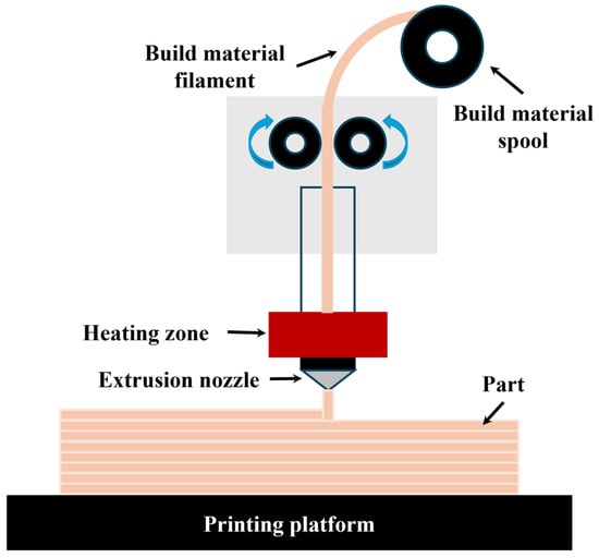
Figure 1.
Schematic representation of the fused filament fabrication process.
Among the various parameters, nozzle diameter and printing speed play critical roles in determining mechanical performance. The nozzle diameter directly affects the amount of material deposited, influencing surface quality, dimensional precision, and the degree of interlayer bonding [12,13]. Larger nozzles improve material flow and reduce build time but may compromise fine features and resolution, whereas smaller nozzles enhance surface finish at the cost of increased printing time and a higher risk of clogging [14,15]. The tensile strength achieved is dependent on the degree of layer fusion, which varies with nozzle size and material properties [16].
Printing speed similarly impacts mechanical behavior by dictating the time available for interlayer bonding. Higher speeds can accelerate production but often result in incomplete fusion and greater void content due to insufficient thermal bonding [17,18]. Conversely, slower printing speeds tend to produce stronger components by allowing more effective diffusion and crystallization between layers, albeit at the expense of productivity. The relationship between printing speed and mechanical strength is non-linear and is affected by thermal conductivity, melt viscosity, and the crystallinity of the polymer [19,20,21].
Recent investigations have examined the influence of individual FFF parameters—including layer height, extrusion width, nozzle temperature, and printing speed—on the mechanical performance of PLA components [22]. These parameters have been shown to affect not only tensile behavior but also compressive strength and surface finish. Additionally, fatigue performance has been studied under both static and cyclic loading conditions, with attention to factors such as temperature cycling and infill architecture [23,24].
Material selection significantly influences printability and final part performance. PLA and ABS, although both widely used in FFF, differ markedly in thermal behavior and mechanical characteristics. ABS, being amorphous with a higher glass transition temperature, typically requires slower deposition rates and larger nozzle diameters to minimize warping and enhance bonding [25,26,27]. In contrast, PLA is semi-crystalline, solidifies more rapidly, and often performs optimally at moderate speeds and nozzle sizes [28]. Furthermore, PLA’s biodegradability and biocompatibility make it advantageous for biomedical and environmentally sensitive applications [29,30]. While many studies have evaluated these materials independently, comparative assessments under identical process conditions remain limited.
Although several investigations have addressed the effects of raster angle, layer thickness, raster width, and infill density on mechanical performance, much of the existing work has been parameter-specific or material-specific. For example, surface quality and dimensional accuracy have been correlated with raster width, contour width, and layer thickness [31], while the mechanical performance of PLA has been linked to parameters such as layer thickness and raster angle [32], and ABS to infill percentage and layer thickness [33]. Additional process variables, including raster pattern, contour number, and air gap, have also been shown to influence tensile and flexural properties [34,35,36]. Some studies have focused on optimizing a single mechanical attribute, such as tensile strength [37], whereas others have employed multi-objective optimization approaches to enhance multiple performance metrics [38,39].
Despite these advancements, a critical knowledge gap remains regarding the combined influence of nozzle diameter and printing speed on the mechanical properties of both PLA and ABS when processed under a unified experimental framework. Specifically, there is limited data on how these parameters interact to affect tensile strength, yield strength, and ductility across different polymer types. Furthermore, most existing studies have not incorporated detailed microstructural analysis to correlate mechanical outcomes with internal morphology and fracture mechanisms.
To address these limitations, the present study systematically investigates the effects of nozzle diameter (0.05–0.25 mm) and printing speed (15–80 mm/s) on the tensile behavior of FFF-printed PLA and ABS. Standardized tensile specimens were produced according to ASTM D638-Type IV, and mechanical properties including ultimate tensile strength, yield strength, and elongation at break were measured. Fracture surfaces were analyzed using microscopy to elucidate the relationship between process parameters and failure modes. This dual-material, parameter-driven approach provides a comprehensive understanding of how nozzle and speed settings influence performance, enabling informed parameter selection for application-specific optimization.
2. Materials and Methods
This section details the materials and methods used to investigate how nozzle diameter and printing speed affect the mechanical properties of ABS and PLA, common FFF thermoplastics.
2.1. Materials
ABS is a widely used thermoplastic known for its high toughness, good impact resistance, and dimensional stability under load [40,41]. Its non-crystalline, amorphous molecular structure allows it to maintain strength across a wide temperature range, making it suitable for engineering-grade applications. In this study, ABS filament with a diameter of 1.75 mm was selected from BestFilament. However, ABS also has a relatively low glass transition temperature, making it prone to thermal deformation such as warping or shrinkage during printing. To manage this, controlled bed and chamber temperatures were applied during the fabrication process [42,43]. Despite offering superior toughness and ductility compared to PLA, ABS is more sensitive to thermal fluctuations and typically requires higher processing temperatures and enclosed printing environments.
PLA is a biodegradable, semi-crystalline thermoplastic made from renewable sources such as corn starch and sugarcane [25,26,44]. It is widely used in 3D printing due to its low warping tendency, ease of processing, and environmentally friendly profile. The PLA filament used in this work also had a diameter of 1.75 mm and was supplied by BestFilament. Unlike ABS, PLA solidifies rapidly and requires no heated bed, but its semi-crystalline nature introduces complexities in its thermal behavior. The crystallinity developed during cooling influences both the stiffness and brittleness of the final part [27,45]. PLA tends to exhibit higher tensile strength, but lower impact resistance compared to ABS. The sensitivity of PLA to cooling rates and its tendency to become brittle under fast solidification conditions necessitate careful control of thermal gradients during printing [26,44,46].
The distinct differences in mechanical and thermal behavior between ABS and PLA—arising from their amorphous and semi-crystalline structures, respectively—are critical to understanding their performance under varying FFF process parameters. Table 1 summarizes the key physical, mechanical, and thermal characteristics of both materials.

Table 1.
Comparison of physical, mechanical, and thermal properties of ABS and PLA [27,47].
2.2. Three-Dimensional (3D)Printing Equipment and Software
2.2.1. Three-Dimensional (3D)Printer
A PICASO FFF 3D printer was used to fabricate all tensile test specimens due to its versatility, affordability, and ability to accommodate a variety of filament materials [48]. Crucially, this printer supports interchangeable nozzles, enabling detailed analysis of how nozzle diameter influences mechanical performance. These highly specialized micro-nozzles were purchased from REC company, Moscow, Russia. Its open-source firmware provides flexibility in adjusting experimental settings beyond standard commercial limits. Prior to printing, the printer underwent comprehensive calibration and leveling to ensure precise material deposition and dimensional accuracy. A glass print bed was employed to enhance adhesion, thereby reducing warping and improving the overall print quality. Key technical specifications of the printer are provided in Table 2.

Table 2.
Technical specifications of the PICASO 3D printer.
2.2.2. Slicing Software
The open-source Polygon slicing software (version 2) was employed to generate G-code instructions tailored to the PICASO FFF printer used in this study [49]. Its flexibility in adjusting a broad range of process parameters—including layer height, infill geometry, print speed, and extrusion temperature—enabled precise control over printing conditions. This level of customizability was essential for systematically isolating the effects of nozzle diameter and printing speed on mechanical performance, ensuring that all other printing parameters remained constant throughout the experiments.
2.3. Specimen Design and Preparation
2.3.1. Tensile Specimens
Specimens were printed following the ASTM D638-Type IV standard [50], which specifies dimensions ideal for tensile testing of thin, flexible polymeric materials typically produced by FFF. This standardization ensured the reliability and comparability of mechanical test results across different parameter settings.
2.3.2. Printing Parameters
A controlled experimental design was implemented to systematically investigate the influence of two key FFF parameters: nozzle diameter and printing speed (Table 3). To isolate the effect of each variable, all other printing parameters were held constant during testing. Specifically, when assessing nozzle diameter, the printing speed and other settings were fixed. Conversely, when evaluating the effect of printing speed, a single nozzle diameter was maintained throughout to ensure experimental consistency.

Table 3.
Selected process condition values for 3D printing of ABS and PLA samples.
The nozzle diameters selected for this study were 0.05 mm, 0.10 mm, 0.15 mm, 0.20 mm, and 0.25 mm. These values encompass a practical range commonly utilized in both prototyping and functional component manufacturing. Similarly, the printing speeds investigated included 15, 30, 45, 60, and 80 mm/s. The chosen parameter ranges were based on a thorough review of the literature, alignment with standard practice in additive manufacturing, and compatibility with the operational constraints of the FFF printer and the thermoplastics employed [5,14,17].
Each nozzle diameter offers a distinct balance between printing resolution and material throughput. Smaller diameters, such as 0.05 mm, provide higher detail and precision, which is critical for fine-feature applications. However, they typically result in longer build times and an increased risk of clogging. In contrast, larger diameters up to 0.25 mm enable higher material flow rates and reduced printing time, although they may compromise geometric accuracy and surface resolution. Printing speed similarly influences part quality and efficiency. Slower speeds tend to enhance layer adhesion, surface finish, and dimensional precision, while higher speeds improve throughput with only moderate reductions in part fidelity, depending on material and geometry.
Preliminary fabrication trials confirmed that the selected ranges of nozzle diameter and printing speed produced stable, defect-free prints exhibiting acceptable dimensional accuracy and surface finish. To minimize variability and ensure reproducibility, several parameters were maintained constant across all tests. A uniform layer height of 0.2 mm was applied, as this setting influences both mechanical properties and build duration. Infill density was fixed at 50% using a hexagonal pattern, ensuring consistent internal structure and load distribution across samples.
Material-specific thermal settings were applied to ensure adequate extrusion performance. For PLA, the extrusion temperature was set at 210 °C with a bed temperature of 60 °C, while ABS was processed at 230 °C with a bed temperature of 110 °C. These values were selected to optimize melt flow, interlayer adhesion, and minimize warping or delamination. Other print settings, including retraction distance, cooling fan operation, and travel speed, were maintained at the default values defined by the slicing software to limit experimental noise and enhance repeatability [20,51,52].
2.3.3. Layer Thickness
Layer thickness, a key parameter in fused filament fabrication (FFF), determines the vertical resolution of printed components and significantly influences surface quality, dimensional precision, and mechanical performance. Employing thinner layers generally results in smoother surface finishes and enhanced interlayer adhesion, attributed to improved thermal overlap and uniform material deposition during the printing process [53,54]. This enhanced bonding reduces the likelihood of interfacial voids and contributes to greater tensile strength and structural integrity of the printed parts [55].
However, increasing the layer thickness, while advantageous in reducing overall printing time, introduces adverse effects on surface morphology. Specifically, it accentuates the staircase effect—a stepped surface pattern that arises due to the discrete nature of layer-by-layer deposition. This effect is especially pronounced on inclined or curved geometries, leading to elevated surface roughness and the formation of localized stress concentrations. These surface discontinuities can act as initiation sites for mechanical failure under load, thereby compromising the strength and reliability of the component [56].
In this study, the layer thickness was held constant across all experimental conditions to isolate the effects of nozzle diameter and printing speed. This control was essential for eliminating a major source of variability and ensuring that any observed differences in tensile strength and elongation were attributable solely to the primary parameters under investigation. By maintaining consistent layer thickness, the study ensured accurate and reproducible comparisons of mechanical behavior across all printed specimens.
2.3.4. Air Gap
Air gap refers to the spacing between adjacent extrusion paths within a single printed layer in Fused Filament Fabrication (FFF). A positive air gap creates intentional spacing between the deposited lines, increasing internal porosity and reducing mechanical strength due to poor inter-raster bonding. Conversely, a negative air gap, where extrusion paths overlap, can enhance bonding strength but often leads to material accumulation, causing surface irregularities and dimensional inaccuracies. In this study, a zero-air gap configuration was employed, in which adjacent lines are deposited precisely side by side with no overlap or gap. This setting was selected to promote consistent inter-raster bonding while maintaining smooth surface quality and dimensional stability [57]. Controlling the air gap is crucial for optimizing the mechanical performance of printed parts, as it directly affects internal density, structural continuity, and the efficiency of load transfer across layers.
2.4. Sample Preparation and Conditioning
2.4.1. Specimen Preparation
Tensile specimens were fabricated in accordance with the ASTM D638-Type IV standard [50,58,59], which is widely recognized for evaluating the tensile properties of thermoplastics and is particularly suitable for FFF due to the anisotropic characteristics introduced by layer-by-layer deposition. The Type IV geometry, characterized by a narrow cross-section and extended gauge length, is ideal for assessing the mechanical behavior of flexible thermoplastics such as PLA and ABS.
Figure 2 illustrates the overall workflow for specimen preparation and testing, including the tensile specimen geometry (Figure 2a), slicing process (Figure 2b), printed samples (Figure 2c), the PICASO open-source FFF 3D printing system (Figure 2d), and the tensile testing setup (Figure 2e). For each specific combination of material, nozzle diameter, and printing speed, three specimens were fabricated to ensure statistical reliability and to account for variability inherent in the FFF process. All samples were printed flat along the XY-plane to maintain consistent layer orientation and minimize anisotropic effects in mechanical performance. G-code generation was performed using Polygon slicing software, with all parameters held constant except for the variable under investigation. The PICASO printer provided precise control over fabrication conditions, ensuring reproducibility across all experimental batches.
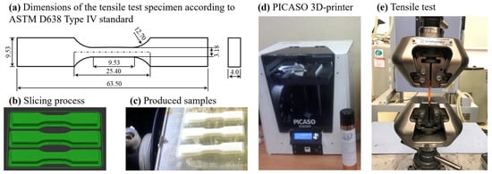
Figure 2.
(a) Dimensions of the tensile test specimen according to ASTM D638-Type IV standard, (b) printing samples through slicing process, (c) produced tensile samples, (d) general view of PICASO 3D-printing system, and (e) experimental setup for tensile testing using a universal testing machine.
2.4.2. Tensile Testing
Mechanical testing was performed using a universal testing machine (SHIMADZU, Kyoto, Japan) with a 100 kN load cell, as shown in Figure 2e. The load cell was calibrated to match the expected tensile range of PLA and ABS, ensuring high measurement accuracy. All tests followed the ASTM D638-Type IV standard [50], employing a constant crosshead speed of 5 mm/min. Force–displacement data were recorded at a sampling rate of 100 Hz to ensure precise capture of the mechanical response. From these data, key tensile properties—ultimate tensile strength, yield strength, and elongation at break—were determined. For each experimental condition, results were averaged over ten specimens, and corresponding standard deviations were calculated to assess the impact of nozzle diameter and printing speed on tensile behavior.
2.5. Fractographic Analysis
Fracture surfaces of tested specimens were examined using optical microscopy and 3D laser scanning microscopy (Olympus LEXT OLS 5100, Tokyo, Japan) to understand failure mechanisms. This analysis provided detailed visual evidence of features such as interlayer voids, filament separation, and surface roughness, which are directly related to print quality. These features were linked to the observed mechanical performance, allowing correlations between microstructural integrity and tensile behavior [60,61,62].
3. Results
3.1. Effects of Printing Speeds on Mechanical Properties
Printing speed is a critical process parameter in FFF, as it directly influences both the mechanical integrity of printed components and the overall efficiency of production. While increasing the speed can significantly reduce printing time and operational costs, it may adversely affect mechanical strength due to insufficient interlayer bonding. This effect is particularly pronounced in vertically oriented prints, where layers are perpendicular to the tensile load direction and rely heavily on bonding strength. In contrast, prints in flat or edge orientations, which align more closely with the extrusion direction, are generally less susceptible to speed-induced defects. Therefore, selecting an appropriate printing speed necessitates a careful trade-off between mechanical performance and production efficiency, considering both material behavior and part orientation.
3.1.1. Effects of Different Printing Speeds on Tensile Strength for ABS Printed Samples
The mechanical properties of ABS components fabricated through FFF using a 0.25 mm nozzle diameter exhibit a pronounced sensitivity to variations in printing speed. Tensile strength, in particular, demonstrates a non-linear dependence on this parameter, as evidenced by the stress–strain curves in Figure 3 and the corresponding summary in Figure 4. The peak tensile strength of 60.74 MPa was obtained at an intermediate speed of 45 mm/s. Deviations from this optimal speed resulted in a marked reduction in strength, with values declining to 53.55 MPa at 15 mm/s and 49.44 MPa at 80 mm/s, corresponding to 13.4% and 22.8% reductions, respectively. These reductions are attributed to the thermal and rheological conditions during deposition. Moderate speeds likely facilitate optimal heat transfer and polymer chain entanglement across interfaces, enhancing interlayer cohesion. Conversely, low speeds may result in thermal degradation or irregular extrusion due to prolonged heat exposure, while high speeds limit bonding time and promote void formation due to insufficient heat conduction between layers.
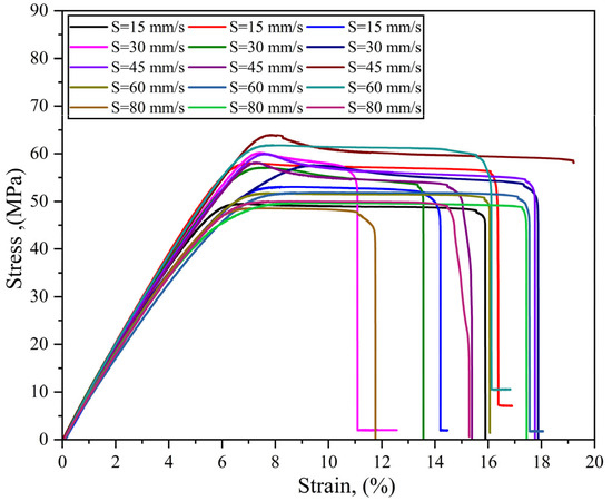
Figure 3.
Stress–strain curves of ABS samples printed at 0.25 mm nozzle diameter under varying speeds (S), with each condition repeated three times.
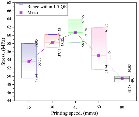
Figure 4.
Maximum, minimum, and mean tensile strength of ABS samples printed at various speeds using a 0.25 mm nozzle diameter.
In addition to tensile strength, strain at failure displayed a variable response to changes in printing speed, as shown in Figure 5. A peak average strain of 0.175 was recorded at 45 mm/s, indicating the highest ductility among the tested conditions. Lower speeds of 15 mm/s and 30 mm/s yielded reduced strain values of 0.158 and 0.147, respectively. Although 60 mm/s produced a relatively high average strain of 0.170, the strain again decreased to 0.148 at 80 mm/s. These observations suggest that interlayer bonding quality and internal stress distribution are optimized at intermediate speeds. At lower speeds, the increased thermal input may adversely affect material homogeneity and lead to embrittlement, while at higher speeds, insufficient fusion across deposited filaments can contribute to poor deformation capacity under tensile loading.
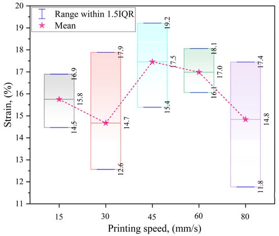
Figure 5.
Effect of printing speed on the strain at failure (max, min, and mean strain) of ABS printed samples at printing nozzle diameter of 0.25 mm.
The overall trends in both tensile strength and ductility emphasize the influence of printing speed on layer integrity, void formation, and thermal gradients during the additive manufacturing process. Intermediate speeds appear to provide a favorable balance of deposition time and thermal diffusion, promoting strong interfacial adhesion and uniform mechanical performance. In contrast, extreme speeds—either too low or too high—are associated with processing limitations that reduce mechanical reliability, such as heat-induced degradation or inadequate polymer flow. This complex relationship highlights the need for precise control over process parameters to ensure consistent mechanical performance in FFF-printed ABS structures.
3.1.2. Effect of Different Printing Speeds on Tensile Strength for PLA Printed Samples
The tensile strength of PLA fabricated via FFF exhibited a non-linear relationship with printing speed, showing optimal performance at intermediate speeds. As indicated in Figure 6 and Figure 7, the maximum tensile strength of 90.29 MPa occurred at 30 mm/s, followed closely by 89.59 MPa at 45 mm/s. In contrast, a decline in strength was observed at both lower and higher speeds, with values of 89.50 MPa at 15 mm/s and 84.04 MPa at 80 mm/s, respectively. The 7.4% reduction from the peak at 30 mm/s to the minimum at 80 mm/s highlights the sensitivity of mechanical performance to deposition rate. This performance trend indicates that PLA benefits from a moderate speed range that facilitates optimal bonding conditions, while deviations from this range introduce structural weaknesses.
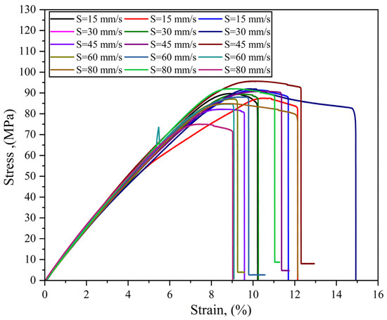
Figure 6.
Stress–strain curves of PLA samples printed at various speeds (S) using a 0.25 mm nozzle diameter.
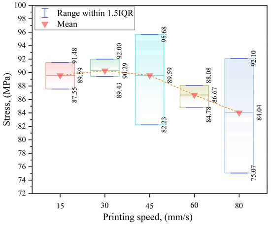
Figure 7.
Maximum, minimum, and mean tensile strength of PLA samples printed at various speeds using a 0.25 mm nozzle diameter.
Thermal dynamics during the printing process significantly influenced this performance. At moderate speeds, molten PLA retains sufficient thermal energy and dwell time to enable effective interlayer diffusion and consistent crystallization, promoting mechanical strength. In contrast, increased printing speeds reduce the bonding window, leading to poor fusion, elevated porosity, and diminished crystallinity. Conversely, slower speeds increase exposure to thermal degradation and residual stress accumulation due to prolonged heating. These factors collectively affect the structural coherence of printed layers and demonstrate the necessity of balancing heat transfer and cooling profiles to maintain interfacial integrity.
Strain at failure showed a similar dependency on printing speed. As illustrated in Figure 8, the peak strain of 0.118 was achieved at 30 mm/s, indicating enhanced ductility. This value declined progressively with increased speed, reaching a minimum of 0.097 at 60 mm/s, before a partial recovery to 0.108 at 80 mm/s. The decrease in strain at higher speeds is associated with inadequate interlayer fusion and increased defect formation, while the reduction at lower speeds may result from thermal aging or non-uniform deposition. These trends underscore the importance of process stability in determining the ductile response of PLA during tensile loading.
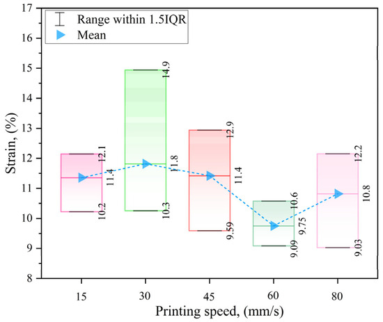
Figure 8.
Effect of printing speed on the strain at failure of PLA printed samples at printing nozzle diameter of 0.25 mm.
The observed variations in tensile strength and strain highlight the complex interplay between thermal behavior, crystallization dynamics, and layer adhesion inherent to PLA’s semi-crystalline structure. Minor fluctuations in cooling rate, temperature gradient, or material flow can lead to measurable deviations in mechanical properties. Therefore, the optimization of FFF parameters—particularly printing speed—must be tailored to PLA’s thermal and rheological characteristics to achieve consistent mechanical performance. The findings emphasize the critical role of maintaining thermal equilibrium during deposition to ensure uniform crystallinity, minimize void formation, and enhance structural robustness across all printed layers.
3.2. Effects of Nozzle Diameter Variation on Mechanical Properties
Nozzle diameter significantly affects material flow, cooling behavior, and layer bonding in FFF. Larger nozzles allow higher material deposition rates, reducing print time and enhancing tensile strength through improved interlayer adhesion. However, faster cooling can restrict molecular diffusion, decreasing ductility and increasing brittleness. In contrast, smaller nozzles promote gradual cooling and better molecular bonding, leading to higher dimensional accuracy and surface quality, but with longer print durations. Therefore, optimizing nozzle diameter requires balancing mechanical performance with print resolution and efficiency, based on specific application demands.
3.2.1. Effects of Different Nozzle Sizes on Tensile Strength for ABS Printed Samples
The effect of nozzle diameter on the tensile strength of ABS samples is detailed in Figure 9 and Figure 10. A progressive increase in tensile strength was observed as nozzle size increased from 0.05 mm to 0.20 mm, with the mean tensile strength rising from 56.46 MPa to 60.90 MPa, corresponding to a 7.9% improvement. This enhancement is primarily attributed to higher material deposition rates, which maintain elevated interfacial temperatures, facilitate stronger interlayer adhesion, and reduce porosity. Notably, the increase between 0.15 mm and 0.20 mm was more pronounced than other intervals, whereas the improvement from 0.20 mm to 0.25 mm was marginal, indicating a diminishing return beyond a certain diameter. These findings suggest that beyond a threshold, secondary factors such as localized overheating, residual stress formation, and changes in melt rheology influence the mechanical behavior more significantly than geometric scaling alone.
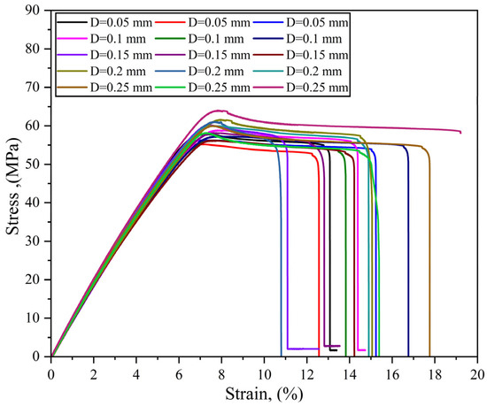
Figure 9.
Stress–strain curves for ABS samples as a function of nozzle diameter (D). All samples were printed at an optimal speed of 45 mm/s, with each condition replicated three times.
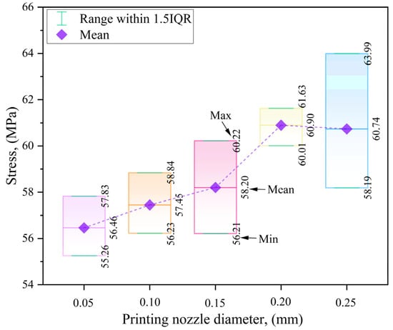
Figure 10.
Effect of nozzle diameter on the tensile strength (max, min, and mean stress) of ABS printed samples at optimal printing speed of 45 mm/s.
As shown in Figure 9, stress–strain curves for each nozzle size exhibited intra-group variation, reflecting sensitivity to thermal stability, filament quality, and printer calibration. These factors introduce microstructural inconsistencies that influence stress distribution and failure mechanisms. Despite this variability, the aggregated tensile strength values in Figure 10 provided consistent trends that support the positive influence of increased nozzle diameter on load-bearing capacity.
In contrast, the strain at failure, as depicted in Figure 11, demonstrated a non-linear response. Strain initially rose from 0.137 at 0.05 mm to 0.151 at 0.10 mm, followed by a decrease to 0.134 and 0.146 at 0.15 mm and 0.20 mm, respectively. A notable increase to 0.175 at 0.25 mm suggests an inflection point in ductile behavior, likely influenced by enhanced thermal diffusion and layer cohesion.
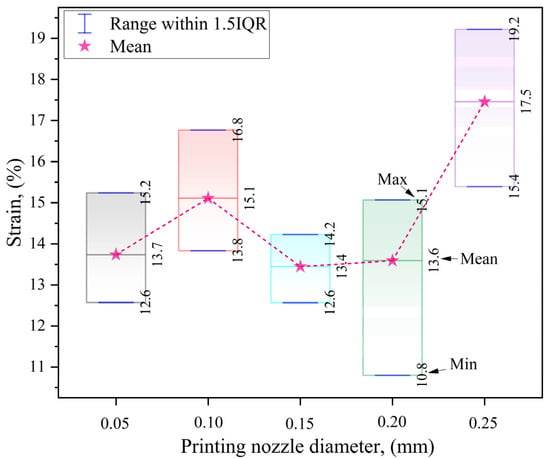
Figure 11.
Effect of nozzle diameter on the strain at failure (max, min, and mean strain) of ABS printed samples at optimal printing speed of 45 mm/s.
The mechanical response of ABS under varying nozzle diameters highlights the interplay between material flow dynamics and thermal management during printing. The general trend of increasing tensile strength with nozzle diameter affirms the role of higher thermal mass in promoting strong interlayer fusion. However, the observed fluctuations in strain indicate that ductility is more closely governed by thermal gradients and cooling profiles. Larger nozzles facilitate slower solidification and greater chain mobility, thereby enhancing deformation capacity, while smaller nozzles constrain chain alignment, leading to brittle fracture modes. The strain peak at 0.25 mm may signify a transition toward more ductile failure behavior due to increased thermal uniformity and improved polymer diffusion. These results underscore the necessity of optimizing both strength and ductility in selecting nozzle diameter, particularly for applications requiring energy absorption, impact resistance, or mechanical flexibility.
3.2.2. Influence of Nozzle Diameter on PLA Tensile Properties
The influence of nozzle diameter on the tensile behavior of PLA exhibited a non-linear and more intricate pattern compared to that of ABS, reflecting the greater sensitivity of PLA to thermal and crystallization dynamics during the fused filament fabrication (FFF) process. As shown in the stress–strain profiles (Figure 12) and summarized tensile strength data (Figure 13), there was no uniform enhancement in tensile performance with increasing nozzle diameter. While the 0.25 mm nozzle produced the highest average tensile strength of approximately 89.59 MPa, the 0.10 mm nozzle unexpectedly yielded a higher maximum tensile strength (83.95 MPa) than the 0.15 mm nozzle. This non-monotonic trend indicates that an increase in nozzle diameter does not linearly translate into superior mechanical strength for PLA, in contrast to the more consistent behavior observed in ABS samples.
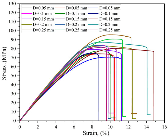
Figure 12.
Stress–strain curves for PLA samples, printed with varying nozzle diameters (D), tested at an optimal printing speed of 45 mm/s.
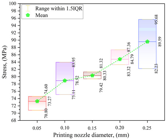
Figure 13.
Effect of nozzle diameter on tensile strength (max, min, and mean stress) of PLA printed samples at optimal printing speed of 45 mm/s.
The deviation from a simple geometric–mechanical relationship can be explained by PLA’s pronounced sensitivity to thermal gradients, cooling rates, and crystallinity development during solidification. Larger nozzles, which facilitate higher volumetric deposition, tend to reduce the cooling rate, theoretically enhancing interlayer bonding due to prolonged diffusion time and improved polymer chain entanglement. However, they may also create thermal inconsistencies across the print cross-section, resulting in heterogeneous crystallization and reduced mechanical uniformity. On the other hand, smaller nozzles promote faster cooling and finer extrusion paths, increasing geometric accuracy but potentially leading to poor interfacial adhesion and reduced molecular mobility. These competing thermomechanical effects contribute to the observed irregular tensile performance across the different nozzle diameters.
The complex mechanical response is further reflected in the strain-at-failure behavior illustrated in Figure 14. Unlike tensile strength, strain values did not follow a predictable progression. Initial strain decreased from 0.107 at 0.05 mm to 0.099 at 0.10 mm, then peaked at 0.123 for the 0.15 mm nozzle before declining to lower values at larger diameters. This suggests that intermediate nozzle sizes may achieve a more favorable balance between adequate bonding and controlled cooling, enabling improved energy absorption and plastic deformation. The lower strain values at the extreme nozzle sizes (0.05 mm and 0.25 mm) likely result from two distinct mechanisms: brittle failure due to insufficient interlayer fusion at small diameters, and possible thermal degradation or bonding inconsistencies at larger diameters, respectively.
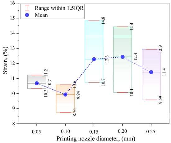
Figure 14.
Effect of nozzle diameter on strain at failure (max, min, and mean stress) of PLA printed samples at optimal printing speed of 45 mm/s.
The results underscore the complex relationship between nozzle geometry and mechanical performance in PLA-based FFF. Unlike ABS, where increased nozzle diameter correlates more consistently with improved strength, PLA’s behavior is governed by a more delicate interplay of geometric parameters, heat transfer, and material-specific crystallization kinetics. Hence, the selection of an optimal nozzle diameter must be based on a comprehensive evaluation of both tensile strength and ductility, tailored to the mechanical demands and functional criteria of the final product. The findings emphasize the need for application-specific optimization in PLA printing, particularly in contexts requiring mechanical resilience and structural uniformity.
3.3. Comparison Between Mechanical Properties of ABS and PLA Based on Printing Nozzle Diameters and Printing Speeds
3.3.1. Tensile Strength Comparison Based on Printing Speed
The comparative evaluation of tensile properties of ABS and PLA under varying FFF conditions reveals critical insights into the influence of printing speed on their mechanical performance, thermal characteristics, and interlayer adhesion. As illustrated in Figure 15, PLA consistently exhibited higher tensile strength across all tested conditions, reaching a peak of 90.29 MPa at a nozzle diameter of 0.25 mm and a printing speed of 30 mm/s. In contrast, ABS achieved a maximum tensile strength of 60.74 MPa under optimized conditions at 45 mm/s and 0.25 mm nozzle diameter, reflecting a 48.6% higher strength for PLA. This significant difference underscores PLA’s inherently stiffer molecular structure and greater capacity for load-bearing applications when precise thermal control is ensured.
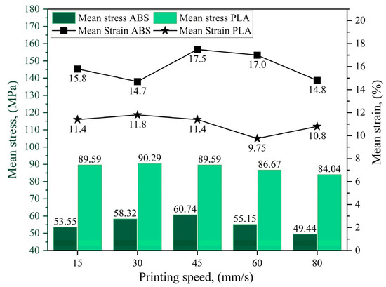
Figure 15.
Comparison of tensile strength and strain at failure of ABS and PLA samples as a function of printing speed.
For PLA, the optimal performance was observed at 30 mm/s, where both tensile strength and strain-at-failure attained favorable levels. However, deviations beyond this speed, particularly above 45 mm/s, resulted in substantial reductions in both parameters, indicating that excessive printing speeds hinder thermal residence time, thereby impairing crystallinity and interlayer diffusion. On the other hand, ABS exhibited a broader range of acceptable printing speeds, with its optimal tensile strength and ductility (60.74 MPa and 17.5%, respectively) recorded at 45 mm/s. This broader thermal processing window for ABS suggests enhanced adaptability to speed variations; nonetheless, its overall strength remained inferior to PLA. These results demonstrate that PLA is advantageous in applications where mechanical strength is critical, provided that narrow processing conditions are carefully maintained, whereas ABS offers greater process robustness at the expense of peak mechanical performance.
3.3.2. Tensile Strength Based on Printing Nozzle Diameters at Optimal Printing Speed
As depicted in Figure 16, the effect of nozzle diameter on tensile strength at the optimal printing speed (45 mm/s) revealed distinct material-specific trends. For ABS, tensile strength increased progressively from 56.46 MPa at 0.05 mm to a maximum of 60.9 MPa at 0.2 mm, representing a 7.8% improvement. This enhancement is attributed to increased material flow at larger nozzle diameters, which improves melt bonding, reduces interlayer voids, and promotes better thermal integration across deposited layers. Additionally, the observed increase in ductility supports the notion that improved heat distribution facilitates more uniform stress transfer across layer interfaces. However, at 0.25 mm, a marginal decline in tensile strength was observed, suggesting that beyond a certain threshold, excessive deposition may lead to uneven cooling or elevated residual stress concentrations, which negatively impact structural integrity.
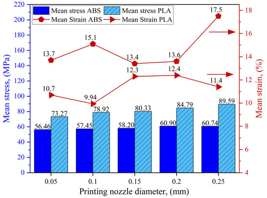
Figure 16.
Comparison of the tensile strength and strain of ABS and PLA samples as a function of nozzle diameter at optimal printing speed of 45 mm/s.
For PLA, tensile strength exhibited a consistent upward trend with increasing nozzle diameter under the same optimal speed of 45 mm/s. The tensile strength improved gradually from 73.27 MPa at 0.05 mm to reach a maximum of 89.59 MPa at 0.25 mm, indicating a cumulative increase of approximately 22.3%. This monotonic enhancement reflects the positive effect of increased material deposition on thermal bonding and interlayer adhesion. Unlike ABS, PLA did not show a strength reduction at higher nozzle diameters within the tested range. However, the strain-at-failure values for PLA did not follow a uniform trend, indicating the involvement of complex thermal–structural interactions. Specifically, smaller nozzles may induce rapid cooling that restricts molecular mobility and limits plastic deformation, whereas larger nozzles can lead to uneven crystallization and internal stresses due to slower and heterogeneous heat dissipation. These findings emphasize the necessity for precise thermal control to fully exploit PLA’s mechanical potential, especially given its semi-crystalline structure and sensitivity to temperature-induced microstructural transformations.
PLA delivered superior tensile strength under optimal printing conditions; however, its mechanical performance was highly dependent on stringent thermal management due to its semi-crystalline morphology and sensitivity to cooling rates. In contrast, ABS, although lower in absolute tensile strength, exhibited more consistent and predictable mechanical responses across a wider range of nozzle diameters and printing speeds. This behavior is facilitated by ABS’s amorphous structure and its broader thermal processing window, which confer greater resilience to variations in fabrication parameters. Consequently, PLA is recommended for applications where high mechanical strength is essential and process control is feasible, while ABS is better suited for applications requiring higher ductility and fabrication robustness.
3.3.3. Fractographic Assessment of ABS and PLA Based on Printing Nozzle Diameters at Optimal Printing Speed
Microscopic examination of the fracture surfaces of FFF-printed ABS and PLA specimens—fabricated at their respective optimal printing speeds using a 0.25 mm nozzle—was conducted using 3D laser scanning microscopy to elucidate the failure mechanisms and interlayer bonding characteristics influenced by nozzle diameter. This analysis provides critical microstructural evidence supporting the observed mechanical performance and highlights material-specific responses to process parameters [63,64].
As shown in Figure 17, the fracture surface of ABS printed with a 0.25 mm nozzle exhibited a relatively smooth morphology with minimal surface roughness and a noticeable absence of voids or microcracks. This surface topography is indicative of ductile failure, where the material undergoes significant plastic deformation prior to fracture. The smooth fracture surface suggests strong interlayer adhesion and effective filament fusion, which are essential for enhancing mechanical integrity. The larger nozzle diameter likely contributed to increased thermal energy deposition and improved melt flow, enabling better wetting and diffusion across adjacent layers. These observations confirm the tensile results shown in Figure 16, where ABS achieved its highest tensile strength under this condition. The enhanced interlayer bonding correlates with previous findings [41], which established that increasing nozzle diameter improves filament coalescence and reduces interfacial defects, thereby strengthening the printed structure.
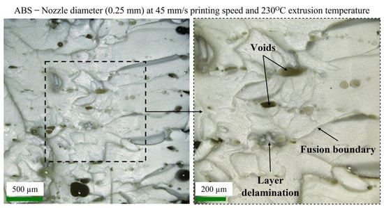
Figure 17.
Optical images of fracture surfaces (surface morphology) of FFF tensile ABS (Flat) sample printed with optimum nozzle diameter (0.25 mm). (Left) Overview of the fracture region; (Right) magnified area.
In contrast, Figure 18 presents the fracture morphology of PLA printed under the same conditions (0.25 mm nozzle, 45 mm/s speed). Unlike ABS, PLA exhibited higher surface roughness, irregular layer boundaries, and visible voids and microcracks. These features are indicative of brittle fracture behavior, characterized by limited plastic deformation and rapid crack propagation through interlayer boundaries. The presence of voids and interfacial gaps points to suboptimal interlayer fusion, which weakens structural continuity and promotes early failure. This brittleness is exacerbated by PLA’s higher crystallinity and faster cooling rate compared to ABS, which may hinder proper bonding between layers when a larger nozzle diameter is used. The increased layer height associated with a 0.25 mm nozzle can introduce thermal gradients and incomplete layer compaction, both of which contribute to the observed porosity and fracture irregularities.
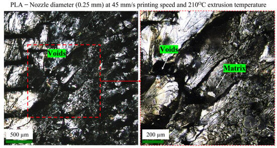
Figure 18.
Optical images of fracture surfaces (surface morphology) of FFF tensile PLA (Flat) sample printed with optimum nozzle diameter (0.25 mm). (Left) Overview of the fracture region; (Right) magnified area.
The comparative assessment underscores the importance of tailoring nozzle diameter to the thermal and rheological characteristics of the material. While a 0.25 mm nozzle optimized mechanical performance in both materials, the fracture surface analysis reveals that ABS benefits more significantly from this configuration due to its amorphous nature and greater tolerance to thermal variation. In contrast, PLA’s semi-crystalline structure and sensitivity to cooling dynamics require more precise control to ensure consistent interlayer fusion. These findings highlight that optimal mechanical performance in FFF is not solely determined by macroscopic process parameters but also strongly influenced by microstructural consolidation and material-specific behaviors during printing.
4. Conclusions
This study investigated the optimization of nozzle diameter and printing speed to enhance the tensile performance of Fused Filament Fabrication (FFF) 3D-printed Acrylonitrile Butadiene Styrene (ABS) and Polylactic Acid (PLA), addressing the challenge of balancing mechanical integrity with processing efficiency. A full-factorial experimental approach was adopted, varying nozzle diameters from 0.05 mm to 0.25 mm and printing speeds between 15 mm/s and 80 mm/s. The results revealed that PLA consistently exhibited higher tensile strength than ABS across all conditions, reaching a maximum of 90.29 MPa at a 0.25 mm nozzle and 30 mm/s speed, which was 48.6% higher than ABS’s peak strength of 60.74 MPa obtained at 0.25 mm and 45 mm/s. PLA’s tensile strength increased by 22.3% with larger nozzles, but declined by 6.6% at higher speeds due to reduced interlayer adhesion. ABS demonstrated a 7.8% strength improvement from 0.05 mm to 0.2 mm nozzle diameter and a 22.8% increase at 45 mm/s compared to 80 mm/s, showing greater tolerance to processing variations. While PLA provided superior mechanical performance, it required narrow parameter windows due to its semi-crystalline nature and sensitivity to thermal conditions. Conversely, ABS offered more predictable responses due to its amorphous structure, making it suitable for applications prioritizing process flexibility and ductility. Optimal conditions were identified as 0.25 mm nozzle and 30 mm/s for PLA, and 0.25 mm nozzle and 45 mm/s for ABS. These findings offer practical guidance for tailoring FFF parameters to achieve enhanced tensile properties based on material-specific behaviors.
5. Practical Implications and Future Work
This study offers practical guidelines for optimizing FFF printing parameters to enhance tensile performance of ABS and PLA. The results suggest that larger nozzles and moderate speeds are ideal for strength-critical applications, while smaller nozzles may suit tasks requiring finer detail despite reduced strength. Future work should investigate multi-variable optimization including infill density, raster angle, build orientation, extrusion temperature, and cooling rate, as these factors influence bonding and dimensional accuracy. Implementing DOE and machine learning could refine process control and prediction. Real-time monitoring of thermal and flow behavior may further improve consistency. Additionally, developing materials with tunable crystallization and rheological properties could expand the functional range of FFF printing.
Author Contributions
Conceptualization, I.S.E. and M.A.P.; methodology, I.S.E., M.A.P., and M.D.; software, I.S.E., E.E. and M.D.; validation, M.E., E.E. and A.A.Z.; formal analysis, M.R.D. and A.A.Z.; investigation, S.E. and A.A.Z.; resources, M.E.; data curation, E.E.; writing—original draft preparation, I.S.E. and M.R.D.; writing—review and editing, M.E.; visualization, A.A.Z. and S.E.; supervision, M.A.P.; project administration, A.A.Z. and S.E.; funding acquisition, M.A.P. and M.E. All authors have read and agreed to the published version of the manuscript.
Funding
This research received no external funding.
Data Availability Statement
Data will be made available on request.
Acknowledgments
The authors acknowledge the valuable contributions of the anonymous reviewers for their constructive feedback, which helped improve the quality of this work. Appreciation is also extended to colleagues for their support and insightful discussions throughout the research process.
Conflicts of Interest
The authors declare no conflicts of interest.
References
- Charia, O.; Rajani, H.; Ferrer Real, I.; Domingo-Espin, M.; Gracias, N. Real-Time Stringing Detection for Additive Manufacturing. J. Manuf. Mater. Process. 2025, 9, 74. [Google Scholar] [CrossRef]
- Godec, D.; Gonzalez-Gutierrez, J.; Nordin, A.; Pei, E.; Ureña Alcázar, J. A Guide to Additive Manufacturing; Springer Nature: Berlin/Heidelberg, Germany, 2022. [Google Scholar] [CrossRef]
- Dekis, M.; Tawfik, M.; Egiza, M.; Dewidar, M. Unveiling the Characteristics of ER70S-6 low Carbon Steel Alloy Produced by wire arc Additive Manufacturing at Different Travel Speeds. Met. Mater. Int. 2024, 31, 325–338. [Google Scholar] [CrossRef]
- Rouf, S.; Malik, A.; Singh, N.; Raina, A.; Naveed, N.; Siddiqui, M.I.H.; Haq, M.I.U. Additive manufacturing technologies: Industrial and medical applications. Sustain. Oper. Comput. 2022, 3, 258–274. [Google Scholar] [CrossRef]
- Yankin, A.; Alipov, Y.; Temirgali, A.; Serik, G.; Danenova, S.; Talamona, D.; Perveen, A. Optimization of Printing Parameters to Enhance Tensile Properties of ABS and Nylon Produced by Fused Filament Fabrication. Polymers 2023, 15, 3043. [Google Scholar] [CrossRef] [PubMed]
- Popescu, D.; Zapciu, A.; Amza, C.; Baciu, F.; Marinescu, R. FDM process parameters influence over the mechanical properties of polymer specimens: A review. Polym. Test. 2018, 69, 157–166. [Google Scholar] [CrossRef]
- Algarni, M.; Ghazali, S. Comparative Study of the Sensitivity of PLA, ABS, PEEK, and PETG’s Mechanical Properties to FDM Printing Process Parameters. Crystals 2021, 11, 995. [Google Scholar] [CrossRef]
- El-Deeb, I.S.; Petrov, M.A.; Grabowik, C.; Esmael, E.G.; Rashad, M.; Ebied, S. Mechanical Properties of PLA Printed Samples in Different Printing Directions and Orientations Using Fused Filament Fabrication, Part 1: Methodology. In Intelligent Systems in Production Engineering and Maintenance III; Springer: Cham, Switzerland, 2024; pp. 643–657. [Google Scholar]
- El-Deeb, I.S.; Petrov, M.A.; Grabowik, C.; Esmael, E.G.; Rashad, M.; Ebied, S. Mechanical Properties of PLA Printed Samples in Different Printing Directions and Orientations Using Fused Filament Fabrication, Part 2: Experimental Research. In Intelligent Systems in Production Engineering and Maintenance III; Springer: Cham, Switzerland, 2024; pp. 627–642. [Google Scholar]
- Tao, Y.; Kong, F.; Li, Z.; Zhang, J.; Zhao, X.; Yin, Q.; Xing, D.; Li, P. A review on voids of 3D printed parts by fused filament fabrication. J. Mater. Res. Technol. 2021, 15, 4860–4879. [Google Scholar] [CrossRef]
- Li, L.; Sun, Q.; Bellehumeur, C.; Gu, P. Composite Modeling and Analysis for Fabrication of FDM Prototypes with Locally Controlled Properties. J. Manuf. Process. 2002, 4, 129–141. [Google Scholar] [CrossRef]
- Blok, L.G.; Longana, M.L.; Yu, H.; Woods, B.K.S. An investigation into 3D printing of fibre reinforced thermoplastic composites. Addit. Manuf. 2018, 22, 176–186. [Google Scholar] [CrossRef]
- Akhoundi, B.; Behravesh, A.H. Effect of Filling Pattern on the Tensile and Flexural Mechanical Properties of FDM 3D Printed Products. Exp. Mech. 2019, 59, 883–897. [Google Scholar] [CrossRef]
- Hsueh, M.-H.; Lai, C.-J.; Chung, C.-F.; Wang, S.-H.; Huang, W.-C.; Pan, C.-Y.; Zeng, Y.-S.; Hsieh, C.-H. Effect of Printing Parameters on the Tensile Properties of 3D-Printed Polylactic Acid (PLA) Based on Fused Deposition Modeling. Polymers 2021, 13, 2387. [Google Scholar] [CrossRef]
- Petrov, M.A.; El-Deeb, I.S.A. Experimental and numerical investigations of mechanical properties of 3D-printed polymeric samples with ideal and roughed surfaces. AIP Conf. Proc. 2019, 2113, 150021. [Google Scholar] [CrossRef]
- Mulcahy, N.; O’Sullivan, K.J.; O’Sullivan, A.; O’Sullivan, L. Preliminary assessment on the effects of line width, layer height and orientation on strength and print time for FDM printing of total contact casts for the treatment of diabetic foot ulcers. Ann. 3D Print. Med. 2023, 11, 100115. [Google Scholar] [CrossRef]
- Tezel, T.; Kovan, V. Determination of optimum production parameters for 3D printers based on nozzle diameter. Rapid Prototyp. J. 2022, 28, 185–194. [Google Scholar] [CrossRef]
- Ansari, A.A.; Kamil, M. Effect of print speed and extrusion temperature on properties of 3D printed PLA using fused deposition modeling process. Mater. Today Proc. 2021, 45, 5462–5468. [Google Scholar] [CrossRef]
- Wu, W.; Geng, P.; Li, G.; Zhao, D.; Zhang, H.; Zhao, J. Influence of Layer Thickness and Raster Angle on the Mechanical Properties of 3D-Printed PEEK and a Comparative Mechanical Study between PEEK and ABS. Materials 2015, 8, 5834–5846. [Google Scholar] [CrossRef] [PubMed]
- Rajan, K.; Samykano, M.; Kadirgama, K.; Harun, W.S.W.; Rahman, M.M. Fused deposition modeling: Process, materials, parameters, properties, and applications. Int. J. Adv. Manuf. Technol. 2022, 120, 1531–1570. [Google Scholar] [CrossRef]
- Hamat, S.; Ishak, M.R.; Sapuan, S.M.; Yidris, N.; Hussin, M.S.; Abd Manan, M.S. Influence of filament fabrication parameter on tensile strength and filament size of 3D printing PLA-3D850. Mater. Today Proc. 2023, 74, 457–461. [Google Scholar] [CrossRef]
- Bakhtiari, H.; Nikzad, M.; Tolouei-Rad, M. Influence of Three-Dimensional Printing Parameters on Compressive Properties and Surface Smoothness of Polylactic Acid Specimens. Polymers 2023, 15, 3827. [Google Scholar] [CrossRef]
- Bakhtiari, H.; Aamir, M.; Tolouei-Rad, M. Effect of 3D Printing Parameters on the Fatigue Properties of Parts Manufactured by Fused Filament Fabrication: A Review. Appl. Sci. 2023, 13, 904. [Google Scholar] [CrossRef]
- Bakhtiari, H.; Nouri, A.; Tolouei-Rad, M. Impact of 3D printing parameters on static and fatigue properties of polylactic acid (PLA) bone scaffolds. Int. J. Fatigue 2024, 186, 108420. [Google Scholar] [CrossRef]
- Oladapo, B.I.; Zahedi, S.A.; Adeoye, A.O.M. 3D printing of bone scaffolds with hybrid biomaterials. Compos. Part B Eng. 2019, 158, 428–436. [Google Scholar] [CrossRef]
- Liu, Z.; Wang, Y.; Wu, B.; Cui, C.; Guo, Y.; Yan, C. A critical review of fused deposition modeling 3D printing technology in manufacturing polylactic acid parts. Int. J. Adv. Manuf. Technol. 2019, 102, 2877–2889. [Google Scholar] [CrossRef]
- Baca Lopez, D.M.; Ahmad, R. Tensile Mechanical Behaviour of Multi-Polymer Sandwich Structures via Fused Deposition Modelling. Polymers 2020, 12, 651. [Google Scholar] [CrossRef] [PubMed]
- Sobron, L.; Sutanto, D. Pengaruh Posisi Orientasi Objek Pada Proses Rapid Prototyping 3d Printing Terhadap Kekuatan Tarik Material Polymer. Sinergi 2016, 20, 229–238. [Google Scholar] [CrossRef][Green Version]
- Qi, X.; Ren, Y.; Wang, X. New advances in the biodegradation of Poly(lactic) acid. Int. Biodeterior. Biodegrad. 2017, 117, 215–223. [Google Scholar] [CrossRef]
- Lopes, M.S.; Jardini, A.L.; Rubens Filho, M. Synthesis and characterizations of poly (lactic acid) by ring-opening polymerization for biomedical applications. Chem. Eng. Trans. 2014, 38, 331–336. [Google Scholar] [CrossRef]
- Bakar, N.S.A.; Alkahari, M.R.; Boejang, H. Analysis on fused deposition modelling performance. J. Zhejiang Univ.-Sci. A 2010, 11, 972–977. [Google Scholar] [CrossRef]
- Rajpurohit, S.R.; Dave, H.K. Analysis of tensile strength of a fused filament fabricated PLA part using an open-source 3D printer. Int. J. Adv. Manuf. Technol. 2019, 101, 1525–1536. [Google Scholar] [CrossRef]
- Srinivasan, R.; Pridhar, T.; Ramprasath, L.S.; Charan, N.S.; Ruban, W. Prediction of tensile strength in FDM printed ABS parts using response surface methodology (RSM). Mater. Today Proc. 2020, 27, 1827–1832. [Google Scholar] [CrossRef]
- Gebisa, A.W.; Lemu, H.G. Investigating Effects of Fused-Deposition Modeling (FDM) Processing Parameters on Flexural Properties of ULTEM 9085 using Designed Experiment. Materials 2018, 11, 500. [Google Scholar] [CrossRef] [PubMed]
- Arif, M.F.; Kumar, S.; Varadarajan, K.M.; Cantwell, W.J. Performance of biocompatible PEEK processed by fused deposition additive manufacturing. Mater. Des. 2018, 146, 249–259. [Google Scholar] [CrossRef]
- Cantrell, J.T.; Rohde, S.; Damiani, D.; Gurnani, R.; DiSandro, L.; Anton, J.; Young, A.; Jerez, A.; Steinbach, D.; Kroese, C. Experimental characterization of the mechanical properties of 3D-printed ABS and polycarbonate parts. Rapid Prototyp. J. 2017, 23, 811–824. [Google Scholar] [CrossRef]
- Rayegani, F.; Onwubolu, G.C. Fused deposition modelling (FDM) process parameter prediction and optimization using group method for data handling (GMDH) and differential evolution (DE). Int. J. Adv. Manuf. Technol. 2014, 73, 509–519. [Google Scholar] [CrossRef]
- Akande, S.O. Dimensional accuracy and surface finish optimization of fused deposition modelling parts using desirability function analysis. Int. J. Eng. Res. Technol 2015, 4, 196–202. [Google Scholar] [CrossRef]
- Rao, R.V.; Rai, D.P. Optimization of fused deposition modeling process using teaching-learning-based optimization algorithm. Eng. Sci. Technol. Int. J. 2016, 19, 587–603. [Google Scholar] [CrossRef]
- Srivastava, V.K. A review on advances in rapid prototype 3D printing of multi-functional applications. Sci. Technol. 2017, 7, 4–24. [Google Scholar] [CrossRef]
- Dawoud, M.; Taha, I.; Ebeid, S.J. Mechanical behaviour of ABS: An experimental study using FDM and injection moulding techniques. J. Manuf. Process. 2016, 21, 39–45. [Google Scholar] [CrossRef]
- Agarwal, K.M.; Shubham, P.; Bhatia, D.; Sharma, P.; Vaid, H.; Vajpeyi, R. Analyzing the Impact of Print Parameters on Dimensional Variation of ABS specimens printed using Fused Deposition Modelling (FDM). Sens. Int. 2022, 3, 100149. [Google Scholar] [CrossRef]
- El-Deeb, I.S.; Grabowik, C.; Esmael, E.; Nabhan, A.; Rashad, M.; Ebied, S. Investigation of Effect of Part-Build Directions and Build Orientations on Tension–Tension Mode Fatigue Behavior of Acrylonitrile Butadiene Styrene Material Printed Using Fused Filament Fabrication Technology. Materials 2024, 17, 5133. [Google Scholar] [CrossRef]
- Farah, S.; Anderson, D.G.; Langer, R. Physical and mechanical properties of PLA, and their functions in widespread applications —A comprehensive review. Adv. Drug Deliv. Rev. 2016, 107, 367–392. [Google Scholar] [CrossRef] [PubMed]
- Ahn, S.H.; Montero, M.; Odell, D.; Roundy, S.; Wright, P.K. Anisotropic material properties of fused deposition modeling ABS. Rapid Prototyp. J. 2002, 8, 248–257. [Google Scholar] [CrossRef]
- Wittbrodt, B.; Pearce, J.M. The effects of PLA color on material properties of 3-D printed components. Addit. Manuf. 2015, 8, 110–116. [Google Scholar] [CrossRef]
- Sheikh, Z.; Najeeb, S.; Khurshid, Z.; Verma, V.; Rashid, H.; Glogauer, M. Biodegradable Materials for Bone Repair and Tissue Engineering Applications. Materials 2015, 8, 5744–5794. [Google Scholar] [CrossRef]
- Mueller, B. Additive Manufacturing Technologies–Rapid Prototyping to Direct Digital Manufacturing; Springer: New York, NY, USA, 2012; Volume 32. [Google Scholar] [CrossRef]
- Rengevič, A.; Fúra, M.; Čuboňová, N. Analysis of printing parameters for production of components with Easy3DMaker printer. Adv. Sci. Technol. Res. J. 2016, 10, 1–8. [Google Scholar] [CrossRef] [PubMed][Green Version]
- Anand Kumar, S.; Shivraj Narayan, Y. Tensile Testing and Evaluation of 3D-Printed PLA Specimens as per ASTM D638 Type IV Standard. In Innovative Design, Analysis and Development Practices in Aerospace and Automotive Engineering (I-DAD 2018); Springer: Singapore, 2019; pp. 79–95. [Google Scholar] [CrossRef]
- Mohamed, O.A.; Masood, S.H.; Bhowmik, J.L. Optimization of fused deposition modeling process parameters: A review of current research and future prospects. Adv. Manuf. 2015, 3, 42–53. [Google Scholar] [CrossRef]
- Kovan, V.; Altan, G.; Topal, E.S. Effect of layer thickness and print orientation on strength of 3D printed and adhesively bonded single lap joints. J. Mech. Sci. Technol. 2017, 31, 2197–2201. [Google Scholar] [CrossRef]
- Rankouhi, B.; Javadpour, S.; Delfanian, F.; Letcher, T. Failure Analysis and Mechanical Characterization of 3D Printed ABS With Respect to Layer Thickness and Orientation. J. Fail. Anal. Prev. 2016, 16, 467–481. [Google Scholar] [CrossRef]
- Li, Z.; Chang, L. Development of Wear-Resistant Polymeric Materials Using Fused Deposition Modelling (FDM) Technologies: A Review. Lubricants 2025, 13, 98. [Google Scholar] [CrossRef]
- Garzon-Hernandez, S.; Arias, A.; Garcia-Gonzalez, D. A continuum constitutive model for FDM 3D printed thermoplastics. Compos. Part B Eng. 2020, 201, 108373. [Google Scholar] [CrossRef]
- Vasudevarao, B.; Natarajan, D.P.; Henderson, M.; Razdan, A. Sensitivity of RP surface finish to process parameter variation 251. In Proceedings of the 2000 International Solid Freeform Fabrication Symposium, Austin, TX, USA, 8–10 August 2000. [Google Scholar] [CrossRef]
- Galantucci, L.M.; Lavecchia, F.; Percoco, G. Experimental study aiming to enhance the surface finish of fused deposition modeled parts. CIRP Ann. 2009, 58, 189–192. [Google Scholar] [CrossRef]
- Maurya, N.K.; Rastogi, V.; Singh, P. Experimental and computational investigation on mechanical properties of reinforced additive manufactured component. Evergreen 2019, 6, 207–214. [Google Scholar] [CrossRef]
- ASTM D638-14; Standard Test Method for Tensile Properties of Plastics. ASTM International: West Coshoshocken, PA, USA, 2003. Available online: www.astm.org (accessed on 5 May 2023).
- Štaffová, M.; Ondreáš, F.; Svatík, J.; Zbončák, M.; Jančář, J.; Lepcio, P. 3D printing and post-curing optimization of photopolymerized structures: Basic concepts and effective tools for improved thermomechanical properties. Polym. Test. 2022, 108, 107499. [Google Scholar] [CrossRef]
- Zhou, L.; Miller, J.; Vezza, J.; Mayster, M.; Raffay, M.; Justice, Q.; Al Tamimi, Z.; Hansotte, G.; Sunkara, L.D.; Bernat, J. Additive Manufacturing: A Comprehensive Review. Sensors 2024, 24, 2668. [Google Scholar] [CrossRef]
- Kirby, S.; Pesun, I.; Nowakowski, A.; França, R. Effect of Different Post-Curing Methods on the Degree of Conversion of 3D-Printed Resin for Models in Dentistry. Polymers 2024, 16, 549. [Google Scholar] [CrossRef]
- Naveed, N. Investigating the Material Properties and Microstructural Changes of Fused Filament Fabricated PLA and Tough-PLA Parts. Polymers 2021, 13, 1487. [Google Scholar] [CrossRef]
- Beníček, L.; Vašina, M.; Hrbáček, P. Influence of 3D Printing Conditions on Physical–Mechanical Properties of Polymer Materials. Polymers 2025, 17, 43. [Google Scholar] [CrossRef]
Disclaimer/Publisher’s Note: The statements, opinions and data contained in all publications are solely those of the individual author(s) and contributor(s) and not of MDPI and/or the editor(s). MDPI and/or the editor(s) disclaim responsibility for any injury to people or property resulting from any ideas, methods, instructions or products referred to in the content. |
© 2025 by the authors. Licensee MDPI, Basel, Switzerland. This article is an open access article distributed under the terms and conditions of the Creative Commons Attribution (CC BY) license (https://creativecommons.org/licenses/by/4.0/).